1
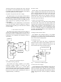
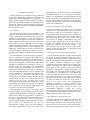
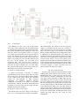
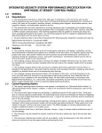
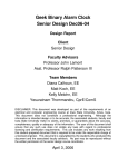
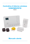
Security Hands Free Entry
System
Anh Loan C. Nguyen, John E. Van Sickle,
Jordan K. Acedera, Christopher Spalding
School of Electrical Engineering and Computer
Science, University of Central Florida, Orlando,
Florida, 32816*2450
Abstract — The project is to utilize radio frequency
identification (RFID) and speaker recognition technology to
create a security hands free entry system. The users will be
able to walk up to the door with both hands preoccupied
using the RFID card and voice to open the door. When the
RFID card is within range, the user will speak a
predetermined phrase of which will be compared to the voice
profile on file. If there's a match, the user is accepted, and
the door automatically opens. The design includes hardware
and software which provides a functionality to allow the door
to be controlled through the authentication of RFID card and
voice by the microcontroller unit.
Index Terms — Access control, security, RFID card,
125Khz frequency, speaker recognition, automatic door.
I. INTRODUCTION
In recent years the problem of home land security has
attracted increasing attention and resources. The search for
solutions that can guarantee greater independence and a
better quality of security has begun to develop easily
available state*of*the*art technology. Intelligent control
systems, most called smart homes, smart environment
systems, intelligent buildings, or intelligent homes can
now be planned and would go far towards simplifying the
interaction between difference technologies. A great
number of benefits would stem from the implementation
of such systems: greater safety, autonomy and self*esteem,
and consequently, better relationships with others.
The proposed project is to utilize Radio Frequency
Identification (RFID) and Voice Recognition technology
to create a Security Hands Free Entry System. The
Security Hands Free Entry System is motivated by the
many times when people are hurriedly entering or leaving
their residence as they are carrying groceries or boxes
which may occupy the use of both hands. With the
completion of this project, one will be able to easily enter
a home or office even with both hands preoccupied.
RFID Technology utilizing a 125 KHz proximity key will
allow the user to unlock a lock within two feet (basic)
from the door they are trying to open. The users will be
able to walk up to the door with their key in their pocket
and unlock the door without having to physically touch
the key. The proximity key would replace manual keys,
swipe cards. The proximity key design will work in
combination with voice recognition to ensure a higher
level of personal security when unlocking the door. A
user spends a few moments enrolling his or her voice in an
application (creating a voice profile). Under normal
operating conditions when the proximity key is within
range, the user will be prompted by the application to
speak a predetermined phrase of which will be compared
to the voice profile on file. If there's a match, the user is
accepted, and the door automatically unlocks. The door
will remain unlocked for a pre*programmed period of
time, and will return to the locked state at the end of the
complete process.
Speaker recognition is one of the most widely used
technological advances of our times. The technology has
made a large progression to make it practical for
commercial consumer use, such as, allowing those with
disabilities the freedom to communicate with others. In
this project, voice recognition will be manipulated to
utilize the capabilities and functionalities of this
technology. We plans to achieve this by combining the
voice recognition technology with the 125 KHz proximity
card access control system.
The system has four main subsystems: Card Access
Control System, the Speaker Recognition System, the
Electric Door Lock System and the PIC microcontroller.
We use Card Access Control System, Speaker
Recognition System, and an electric door locking system
and combine all of them with PIC microcontroller acting
as central control unit to make up a fully integrated
security hands free entry system. In this modern time,
maintaining personal security should be considered of the
utmost importance. What if we lose the card key, what if
someone recorded our voice? With this proposed solution
it will take more effort for an adversary to obtain the card
key and the voice at the same time.
The security hands free entry system is simple and
straightforward.
It is designed so that it is self*
explanatory in its operation and simple for anyone to use
regardless of their educational background even the people
that are not as technologically oriented should be able to
use the system with much ease. Any technological device
should be to facilitate certain aspects of life and not make
matters more complicated.
II. THE SYSTEM DESIGN
The Security Hands Free Entry System consists of
hardware and an application program for microcontroller
unit developed in Hi*Tech C programming language and
MCU voice recognition. The hardware module has four
main subsystems. We will cover these four subsystems in
more details throughout this section. The four main
subsystems include:
• Card Access Control System
• Speaker Recognition System
• Electronic Door System
• PCB PIC Microcontroller.
The control action is actually performed by the
microcontroller. It processes the signals that are inputted
from the valid card reader and voice signal at the entrance.
The output section of the microcontroller is connected via
relays circuit for the desired operational action. The
completed hardware system is shown in figure 1.
Card Access Control System
12 VDC
Power
Supply
ProCard II
MaxiPro
5375
Reader
OEM Reader
Converter
Board
consistent read range and unaffected by body shielding or
variable environment conditions, even when close to keys
and coins. Using ProxCard II with MaxiProx reader can
produce read range up to 24 inches. The ProxCard II
requires a minimum of 5VDC for operation and will
accept up to 16 VDC input. It draws an average of 35 mA
at 12VDC and has a peak current draw of 125 mA. Cards
has encoded as 26 bit Wiegand to utilizing proximity
technology. The card can fit into wallet or purse. It is light
weight, strong, flexible and resistant to breaking.
RFID
CARD
125 KHZ
Electronic Door
System
D34990 Low
Energy
Operator
12 VDC
Power
Supply
DATA 0
READER
CONVERTER
INTERFACE
READER
DATA 1
Printed Circuit
Board
PIC
Microcontroller
Electric
Strike
LED
R232
T232
Relay Circuit
9 VDC
Power
Supply
PIC
MICROCONTROLLER
Magnetic
Door
Position
Switch
Speaker Recognition System
MSP430
SR307
Fig. 1.
12 VDC
POWER
SUPPLY
Request to
Exit Push
Button
Door
Assembly
General Hardware Design Block Diagram
III. CARD ACESS CONTROL SYSTEM
The Card Reader access control system shall provide the
ability to regulate access the door through PIC
microcontroller. We use MaxiPro 5375 for card reader,
Prox card II and Wiegand converter for reader controller
interface. These entire products meet our requirement of
our product which is the reader can read the card at least 2
feet range. The completed card access control system is
shown in figure 2.
A. ProxCard II
Proximity is an access control/identification technology
that utilizes radio frequency (RF) circuits in microchip
form. The microchips are encoded and transmit the
encoded information when activated. The proximity card
is used with its associated proximity card readers.
The RF*programmable Proxcard II is compatible with
all HID proximity readers. ProxCard II is offers extremely
Fig. 2.
Card Access Control System
B. MaxiPro 5375 Long Range Reader
The Reader is used to activate the passive tags with RF
energy and extract information from these tags. They
contain a transmitter, receiver, and digital control module
that interface with the operator interface. The reader
interfaces with its antenna via an interface chip. If a tag is
sensed by the antenna, the reader will transmit the data to
controller. The controller will decode the data and pass it
to the operation interface where is programmed to lock or
unlock the door. The ability to read a tag from much a
greater distance requires much more complicated receiver
circuitry and the ability to generate a higher power RF
magnetic field. Each reader can only talk to its
corresponding card type since each of the technologies is
unique. For HID Proximity 125 kHz, MaxiProx 5375
Reader is ideal for long read range applications. It has
long read range distance up to 6 feet (with ProxPass).
MaxiProx is easily interfaced with all existing Wiegand,
Clock—and –Data, RS*232, RS*422, and RS*8485
protocol access control system [1].
C. Reader Converter Interface
The Wiegand interface is the wiring standard used to
connect access card mechanisms and other security
devices to electronic entry systems that read the input
information. In the Wiegand mode the serial port is able to
receive the data directly from any Wiegand device, such
as card reader and also output the data in the Wiegand
format, as if it was a card reader itself [2]. Wiegand
interface is popular in the security, access control, and
automation industry. The OEM Wiegand converter
requires a regulated power source of 5 VDC or 8*16VDC,
100mA
for
internal
operation.
The
RS*232
communications parameters are: 9600 baud, N no parity, 8
data bits, 1 stop bit and no hardware flow control [3].
Wiegand converter operates with any card reader that
produces a standard Wiegand (Data 1 / Data 0 or Clock
and Data) communication output. Wiegand format is easy
to use, no need to deal with clock. We have designed to
pick out Wiegand format to get data from card reader and
then convert Wiegand data transmit to PIC controller via
RS232 connector. A 26 bit Wiegand format will be used
in the example below.
Input: Wiegand (26*bit)
1 001011010100101100011010 1
Even Parity
Data
Odd Parity
Output: 16*byte ASCII string from RS232 method
00002D4B1A
3 CR
*26#
26*bit Wiegand Data ((2D4B1Ahex) Parity Character
D. Power Supplies
Power Supplies for hardware designed specifically for
the system equipment installed. The MaxiProx 5375
reader requires a linear power supply with a rating of 24 *
28.5 Volts DC at a minimum of 1.5 Amps per reader. A
linear power supply aids maximum reader performance.
The Wiegand converter requires a regulated power source
of 5 VDC or 8*16VDC, 100mA for internal operation. The
reader and reader converter interface has shared 12VDC
power supply. RFID card utilities power from the reader
through radio frequency.
IV. THE SPEAKER RECOGNITION
Simply put, voice recognition is the act of recognizing
an identified speaker’s speech and converting it into text.
In particular, voice recognition systems have to be trained
to a specific user, combining the principles of both
speaker recognition (identifying the speaker) and speech
recognition (determining what words the speaker is
saying). The development of voice recognition systems,
especially their training methods, is mostly due to the fact
that human speech patterns vary from person to person.
Accents, in particular, cause these differences to emerge in
basic speech recognition systems, causing them to behave
in ways not intended. The key difference between the two
components to voice recognition is that speaker
recognition is the process of recognizing the identity of
the speaker whereas speech recognition is the process of
determining what is said by a speaker. We will be using
speaker recognition methods. The basic operation of
speaker recognition is shown in figure 3.
MIC
Input
Input
Filtering
Noise3filtered
voice input
Feature
Selection
Decision
Pattern
Matching
Voice Input
Features
Match
Result
Voice Profile
Database
Fig.3.
Basic Operation of Speaker Recognition
A. Texas Instrument MSP430
The Texas Instruments MSP430 Ultra*Low Power
MCUs are known for their ease of use and low power
consumption. A microcontroller is necessary to interface
the PIC subsystem with the Scientific Instruments Speech
Recognition circuit SR*06. The microcontroller and SR*06
collectively handle user profile management.
B. Images Scientifics
Recognition Circuit SR)06
Instruments
(SI)
Speaker
The SI SR*06 circuit is an unassembled speech
recognition circuit. An alternative is the SR*07 speech
recognition circuit, which provides the exact same
functionality as the SR*06 but comes fully assembled.
Consequently, the SR*07 is more expensive, so for the
purposes of cost*effectiveness we used the SR*06 speech
recognition circuit. Both circuits utilize the HM2007
speech recognition IC. It is a speaker dependent chip
capable of recognizing up to 40 .96*second words or 20
1.92*second words [4].
C. Voice profile
Voice profiles, as stated earlier, will be collectively
managed by the combination of the MSP430 MCU and
the SR*06 Speech Recognition circuit. User identification
will be hard*coded into the MCU based on the passphrase
location the user selects on the SR*06. Program flow for
speaker recognition can describe as follow:
The MCU receives a 3*bit user ID from the PIC. The
speaker then speaks into the SR*06. The SR*06 will
recognize the word as one of twenty possible words from
its memory. The SR*06 will then send the value of the
word (either 1 through 20) as a 6*bit output to the MCU.
The MCU will then compare the value from the SR*06
with the user ID received from the PIC. If the value and
user ID match, a 3*bit confirmation code is sent to the PIC
to confirm a match. If a match is not made, a bit sequence
of all zeros (000) will be sent to the PIC.
D. Speaker Recognition System Power Supply
The SR*06 requires a 9V power supply, which comes in
the form of a standard 9V battery. This poses the problem
of prolonged use; initial testing shows the battery can only
last for a few hours while the circuit is on standby. We can
easily remedy this by replacing the battery with a 9V
power supply.
For the purposes of our demonstration, we will continue
to use the 9V battery, however. Should we decide to
further develop our prototype, we will switch to a constant
9V power supply
V. ELECTRONIC DOOR SYSTEM
The Electric Door System shall provide the ability to
open the door without having to insert a key and turn a
knob utilizing industry standard hardware utilizing proven
technologies. The completed door hardware system is
shown below.
120VAC
Power
B. Electric Strike
Electric strike is also called electric latch release they
replace a standard strike mounted into the door frame and
receive the latch and latch bolt. It has a drop away side
that as energized moves out of the way of the door
mounted lockset. Latches are set to default as either lock
safe or lock secure. This is the mode that the lock would
be in if the power were lost [6].
C. Request to Exit Push Button
The user may desire to exit the interior while utilizing
the electric strike. This push to exit switch enhances the
operation of the system by allowing minimal contact. The
voltage range of request to exit push button is 11.6*
28.5VDC. Requirement for a door exit application would
be a N.O. or Normally. Request to exit Push Button shall
be surface wall mounted about 48” above finish floor on
the interior side of the door.
D. Magnetic Door Position Switch
The magnetic door position switch is an invisible
sensing device. It is used to monitor the status of the door.
The magnetic door position switch is activated when the
door is moved from a closed position.
E. Door Relay Circuit
Relay
Circuit
D34990 Low
Energy Operator
PIC
A simple relay circuit has used to communication
between the door and PIC microcontroller unit. It is a
switch to turn on and off connection between PIC and
door. The door relay circuit is shown in figure 5.
Door
Door Position
Switch
Electric
Strike
D34990 Low Energy Operator
Power Supply
for Lock
PIC
Request to
Exit Push
Button
Fig. 4.
Electronic Door System Block Diagram
A. D)4990 Low Energy Operator
The D*4990 Low Energy Operator is an electro*
mechanical product designed to provide safe and
convenient automatic access. It is a “Power Open”
operator that can be activated with the press of a switch. It
can be used with electric strike.A time delay function is
built into the control system eliminating the need for
supplemental relay or controls [5].
Fig. 5.
Door Relay Circuit Block Diagram
F. Door System Power Supply
A wall mounted step down transformer of the 500 VA
rating was determined to be best suited for our application.
This size will insure future addition of options to include
status buzzer and perhaps lights. This particular design is
readily plugged into the wall not requiring a dedicated
circuit.
VI. PIC MICROCONTROLLER
The PIC subsystem is responsible for tying together all
of the other independently functioning subsystems and
providing the desired functionality to the project as a
whole. The PIC follows a logical sequence of events in
order to provide the desired high*level functionality of the
total system. The PIC’s program includes several built*in
interrupts to adjust to the status of the door throughout the
basic sequence of events.
A. PIC 16F877A
The Microchip PIC16F877A microcontroller is the
centerpiece of the PIC subsystem and really the project as
a whole. Without the microcontroller, none of the other
subsystems would function as they are supposed to
function. In terms of hardware, the PIC16F877A shares an
electric connection with virtually every other aspect of the
project. Many of these components operate at higher
voltages than the microcontroller and carry larger currents;
careful consideration had to be given in designing these
connections. The PIC16F877A operates at frequencies up
to twenty megahertz, voltages in the range of 2.0 V to 5.5
V, and currents as high as two hundred and fifty milliamps
[7].
The microcontroller’s connection to the programmer is
the only connection to a peripheral device that will not
utilize a terminal block. Instead of a terminal block, six
0.025” square pins with 0.100” spacing will be used to
connect to the programmer. The six pins that make up this
connection are designated as VPP/MCLR, VDD Target, VSS
(ground), PGD, PGC, and auxiliary. The VPP/MCLR pin
provides voltage for programming and master clear
functionality. The pin will connect to the VPP/MCLR pin
on the microcontroller through a series of capacitors and
resistors as indicated by the programmer’s data sheet. The
VDD pin and the VSS pin will be connected to their
respective pins on the microcontroller. The PGD pin will
connect to port B at pin seven, while the PGC pin will
connect to port B at pin six. These pins on the
microcontroller provide special functionality for in*circuit
programming. The auxiliary pin will have no connection
to the circuit; however, it will still be included since there
is a specified port for it on the programmer.
The programmer will connect to the printed circuit
board by plugging the programming connector into the
square pin connectors mounted on the board. A USB cable
will be used to connect the programmer to a computer. A
hex file is used to program the microcontroller. The hex
file will be generated from C code by the HiTech C
Compiler. The programmer includes software that will be
used to burn the generated hex file into the
microcontroller’s memory. Once the microcontroller is
successfully programmed, the file will remain in the
microcontroller’s memory until the PIC is erased using the
programmer software or a new program is loaded into
memory. The programmer can be disconnected from the
printed circuit board once programming has been verified
and it is confirmed that the device has been successfully
programmed. The specific connections for each subsystem
are provided in detail below.
B. PIC and Card Reader System Integration
The microcontroller will connect to the card reader
subsystem via a simplified RS*232 protocol connection
that does not require a physical RS*232 connector. A
simple terminal block will be used in place of the RS*232
connector. Because the PIC and reader converter board do
not operate at the same voltage level, a signal converter
was necessary to facilitate communication. The reader
converter board transmits the card ID via the RS*232
protocol. The MAX232 converts the signal to a TTL
format and forwards the converted signal to the
microcontroller. The PIC also draws its power supply
from the reader converter board, so voltage and ground
connections were also necessary.
C. PIC and Voice Recognition System Integration
The microcontroller will share a six*pin connection with
the speaker recognition subsystem. Three pins will be
reserved for output to the speaker recognition subsystem,
while the remaining pin will be maintained for input from
the speaker recognition subsystem. The speaker
recognition subsystem will support up to six unique voice
profiles. The output pins will be used to communicate
which of the six voice profiles is trying to be matched
depending on which card is in range of the reader. The
voice profiles will correspond to three*bit binary outputs
‘001’ through ‘110.’ An output of ‘111’ will indicate that
no match is trying to be made because there is not a valid
card in range of the receiver. The input pins will indicate
the result of the attempted voice match. If the presented
voice does not match the stored voice in the profile, a
value of ‘111’ will be sent to the microcontroller
indicating a mismatch. If a positive match is made
between the presented voice and the stored voice, a value
equal to the voice profile ID will be sent to the
microcontroller indicating a match. All of these
connections will be made with the microcontroller through
a six terminal block. The output pins will be tied to port E,
while the input pins will be tied to port D.
D. PIC and Door Lock System Integration
The microcontroller will communicate with the electric
door latch subsystem in a number of ways. First, the
microcontroller will share a two*pin connection with the
door status switch of the electric door latch subsystem.
One pin will be designated for output, and the other pin
will handle input from the switch. These connections will
allow the microcontroller to keep track of whether the
door is locked or unlocked as any given time. These
connections are necessary because locking the door after
entry is handled internally by the electric door latch
subsystem rather than directly by the microcontroller. The
microcontroller shares an additional one*pin connection
with the electric door latch subsystem that handles
unlocking the door. When activated, this connection will
effectively close the circuit of the electric door latch
subsystem allowing it to unlock the door for a specified
amount of time. The final connection between the
microcontroller and the electric door latch subsystem is a
ground wire to provide a common ground between the
five*volt power supply of the microcontroller and the
twelve*volt power supply of the electric door latch
subsystem. These connections will be made with the
microcontroller through a four terminal block with three
of the terminals tying into port A on the microcontroller
and the remaining terminal connecting to ground on the
printed circuit board. The push to exit button shares no
direct connection with the microcontroller. The
microcontroller will only know that the button has been
pressed through its connection with the door status switch.
Evaluation before it was transmitted to the microcontroller
through the programmer.
F. Stage Diagram:
Figure 6 shows the various states that the system can
take and the actions necessary to proceed through them.
There are five basic states of the system: waiting for card,
waiting for voice, card and voice confirmed, door opened,
and door closed. The function of the microcontroller will
vary depending on the state of the system. Certain actions
will be expected when the system is in one state, while
those same actions will be completely ignored by the
microcontroller if they occur while the system is in
another state. A brief description of the five states of the
system as well as the actions that facilitate changes in state
and state diagram is provided below.
No Voice
Match
Invalid Card
in Range
Waiting for
Card
(Idle)
Valid Card
in Range
Negative
Voice
Match
Door
Closed
Waiting for
Voice
Positive
Voice
Match
E. The PIC Control Program
In order to provide functionality to the microcontroller,
it needs to be programmed. The process of programming a
PIC is often referred to as “burning.” A hex file is required
for burning into the PIC. It is possible to program the hex
file directly, but for the sake of simplicity, a compiler is
often used to generate the file from code written in a more
user*friendly language. There are several C compilers
available for programming PICs.
The PIC control program can be written using a low*
level assembly language or high*level language such as C
or Java. A complier for high*level language helps to
reduce production time. The PICkit2 Microcontroller
Programmer is developed by Microchip, the same
company that develops the PIC16F877A used for this
project. The programmer package contains the PICkit2
Development Programmer/Debugger, the PICkit2
Programming Software, a USB cable, and lessons for
programming PIC microcontrollers. The programmer uses
a USB mini*B connector to connect to a computer and a 6*
pin programming connector to connect it to the target
device. The 6*pin programming connector accepts 0.025”
square pins with 0.100” spacing. In order to connect the
programmer to the microcontroller, it will be necessary to
mount a 6*pin male header connector on the printed circuit
board. The source code has been commented to facilitate
any occasional future improvement and maintenance. The
code written followed all the three steps of microcontroller
program development that is: Compilation, Burning and
Door
Open
Card and Voice
Confirmed
Door Locked
Timer
Expiration or
Door Closed
Unlock
Door
Door Unlocked
Door Open
Fig. 6.
PIC State Diagram
The “Waiting for Card” state is also referred to as the
idle state. This is the state of the system when it is not
currently in use. The system will remain in the “Waiting
for Card” state until a card comes in range of the receiver,
and the card reader subsystem transmits the card
identification to the microcontroller. If the card’s
identification is not among the short list of cards to be
used by the system, the card will be identified as invalid.
No state change occurs when an invalid card is in range of
the receiver. However, if the card’s identifying
information is found in the system, the card will be
deemed valid. When a valid card is in range of the
receiver, the system will proceed to the next state in line,
the “Waiting for Voice” state.
Fig. 7.
PCB Schematic
The “Waiting for Voice” state is the second possible
state of the system. During this state, the microcontroller
is communicating with the speaker recognition subsystem.
The system will remain in the “Waiting for Voice” state
until some kind of voice match is made. If a negative
voice match occurs during this state, the system will revert
back to the “Waiting for Card” state. However, when a
positive voice match is made between the presented voice
and the voice profile, the system will then proceed to the
next state in the sequence, the “Card and Voice
Confirmed” state. This state will cause a cascade of
signals that function to open the door. The system will
then enter the “Door Unlocked” state for a short while.
The system will then progress to the “Door Locked” state
until the door closes, and the cycle begins again.
G. Printed Circuit Board (PCB)
A printed circuit board is necessary to facilitate
communication between the PIC system and every other
aspect of the project. The microcontroller will be mounted
on the printed circuit board, which will electrically
connect the microcontroller to other electronic
components via conductive pathways. Electrical
components are attached to the surface of the printed
circuit board by soldering. The EAGLE PCB software has
been used to create the circuit for the project. The PIC
schematic layout is show in figure 7.
H. PIC Microcontroller Power Supply
The PIC16F877A will accept voltages in the range of
2.0 V to 5.5 V with frequencies as high as 20 megahertz.
The microcontroller will connect to the five*volt power
supply via a terminal block, the same way it connects to
each of the subsystems. This will provide more versatility
than if the power supply were mounted on the board
directly. It makes replacing the power supply easier incase
it malfunctions. A dedicated external power supply was
considered for the PIC microcontroller. However, it made
more sense to use a regulated power signal from the reader
converter board. There is no need for separate power
supplies because the function of the microcontroller relies
on receiving data from the card reader. If the power supply
to the card reader fails, the microcontroller will not be able
to function properly. It makes sense that these two
subsystems share the same power supply.
VII. THE SYSTEM OPERATION
After the system is turned on, the door indicator’s light
emitting diode (LED) come ON after some few seconds,
indicating that door is in the ready state. On the secure
side of the door, red LED is normal status of reader and
voice panel. Person approaches to RFDI range with the
valid RFID card, the LCD green’s reader will flash and
beep once (reader control not from PIC) to indicate that
PIC has acknowledge first identification, then green LCD
on voice panel will turn on, indicated that system need the
second identification which is the voice data. Person is
going to speak his/her password. Once both data have
matched with memory data, then PIC will release the door
contact. The solenoid release with the click sound, door is
opened and both LCD turn red, ready for next
identification.
If the voice profile doesn’t match the system, PIC will
command LEDs on reader and voice panel turn red which
is normal condition, no action to the door. The RFID card
will timeout in about 5*7 second if there is no action
which is repeated wrong voice profile. The system is
waiting for the next card in range. If the reader did not
recognize the valid card in the first place then nothing
happen, no action follow up for voice active either. Reader
works as the filter to activate the voice system.
After the person gets in to the unsecure side, the door
will close and lock by hearing a solenoid’ click. On this
side, we have designed a request to exit push button. Once
the button is pressed, door will open, following a click
sounding from the solenoid. For any others complicate
operation, it can happen but it should be consideration for
the future design.
[3] Wiegand to Serial Converter Reader – RF Ideas.
http://www.rfideas.com/products/wiegand_converters/
[4] Speech Recognition Circuits.
http://www.imagesco.com/kits/speech*recognition*kit.html
[5] PrecisionHardware.com.
http://www.precisionhardware.com/index.asp?Mode=D499
0
[6] Electric Strike – Wikipedia the free encyclopedia
http://en.wikipedia.org/wiki/Electric_strike
[7] PIC16F877A
http://www.microchip.com/wwwproducts/Devices.aspx?dD
ocName=en010242
BIOGRAPHY
VIII. CONCLUSION
This project, being a heavily involved group initiative,
required that each person achieve their individual goal and
responsibility. The project has successfully presented a
functional and low complexity microcontroller based on
voice recognition and door access control system. We
accomplished what we set out to do, make a hands free
door open and closed with the feature of RFID card and
voice recognition. A real*life equivalent of the design can
be developed where high security is required.
ACKNOWLEDGEMENT
The authors wish to acknowledge the assistance and
support of Dr. Samuel Richie, Dr. Michael Georgiopoulos,
Sean P. Wicks, HDR Inc, Michael E. McCoy, Stanley
Security Solutions Inc, Emma Battaglia, HID Global
Corporation,
Herb
Gingold, Texas
Instrument,
WORKFORCE CENTRAL FLORIDA and the University
of Central Florida.
Anh Loan Nguyen would like to acknowledge the
support by WORKFORCE CENTRAL FLORIDA.
John E. Van Sickle would like to acknowledge the
support by WORKFORCE CENTRAL FLORIDA.
Jordan K. Acedera would like to acknowledge the
support by WORKFORCE CENTRAL FLORIDA.
REFERENCES
[1] HID Product MaxiProx5373.
http://www.hidglobal.com/prod_detail.php?prod_id=10
[2] TIDE and Tibbo basic user Manual.
http://docs.tibbo.com/taiko/index.html?ser_clockdata_mode
.htm
Anh Loan Nguyen is currently a
senior Electrical Engineering at the
University of Central Florida. She
will be completing her Bachelor
Degree in fall 2012. After
graduation, she will continue her
career path working for HDR Inc.
John E. Van Sickle is currently a
senior Electrical Engineering at the
University of Central Florida. He
will be completing his Bachelor
Degree in May 2012. He plans to
pursue his Master’s in Business with
future plans towards a PhD in an
emerging technology in electro*
optics, bio*nanotechnology.
Jordan K. Acedera is currently a
Computer
Engineering
undergraduate student at the
University of Central Florida. He
will be completing his Bachelor
Degree in Computer Engineering
this semester.
Christopher Spalding is a senior
Computer Engineering student at the
University of Central Florida. After
earning his Bachelor Degree in
Computer Engineering, Christopher
will begin his graduate studies at the
University of Louisville School of
Medicine.