1
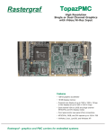
Rastergraf GarnetPMC Conduction-Cooled (CCPMC) High Resolution Single or Dual Channel Graphics with Video/Hi-Res Input Features • Conduction-cooled equivalent to TopazPMC • 128-bit graphics accelerator • 16 MB display memory • Supports one display at up to 1600 x 1200 x 16 bpp or two displays at up to 1280 x 1024 x 8 bpp • Dual channel VGA or LVDS and single channel NTSC/PAL and DVI display modes • Rear-panel (Pn4) connections • NTSC/PAL, RGB, and DVI capture up to 1024 x 768 • VxWorks, Linux, LynxOS, and Windows 2K/XP Rastergraf - graphics and PMC carriers for embedded systems GarnetPMC Rastergraf’s GarnetPMC is a display controller and video capture PMC (PCI Mezzanine Card) board. The card is available with software for a variety of popular operating environments (see page 9). The GarnetPMC is available in both display-only (GarnetPMC/1x, formerly DurosPMC) and display/capture (GarnetPMC/2x) versions. Please refer to Page 5 for more information. Please contact the Rastergraf if you desire a configuration not shown in this data sheet. GarnetPMC features a Silicon Motion SM731 System On a Chip (SOC) graphics accelerator with 16 Mbytes of on-chip SDRAM. This 128-bit 2D/3D graphics engine supports compatible displays at 1600x1200x16 bpp or 1280x1024x24 bpp. The capabilities of the board are discussed in more detail on the following pages. Optional features include a Conexant Bt835 NTSC/PAL/S-Video and Analog Devices AD9882 High Speed RGB/DVI digitizers. A loopback can connect Video Output to Input for self-testing. The standard GarnetPMC configurations are controlled by Rastergraf’s factory configured I/O Resource Matrix, whch maximizes I/O flexibility. Being a CCPMC, all I/O is via the Pn4 rear panel connector. Please refer to Page 4 for a block diagram. Embedded Life-Cycle Support Rastergraf’s comprehensive selection of PMC, CompactPCI, PCI, and VME display and carrier solutions are designed to satisfy the product life-cycle requirements demanded by the embedded computing market. The Embedded Graphics Source. Rastergraf’s SM731-based product line also includes the commercial-range equivalent to the GarnetPMC, which is called the TopazPMC. Additional Rastergraf products include: • Single, dual, and quad display-only PMC. • Single and dual display/capture with audio I/O PMC • Single display-only CPCI and PCI • 3U and 6U VME graphics boards. • CompactPCI and PCI carriers for one or two PMCs. Please contact Rastergraf for more information or consult our web page at www.rastergraf.com.. Optional High Speed RGB and DVI Digitizer IEEE 1386-2001 32 Bit, 33/66 MHz PMC Bus Silicon Motion SM731 Graphics Accelerator with On-chip 16 MB SDRAM Optional NTSC/PAL Video Digitizer Universal PMC Interface (3.3V or 5V Signaling) Rear Panel I/O on PMC Pn4 Field Programmable VGA BIOS EEPROM LM75 Thermal Sensor DVI Transmitter Optional Secondary RGB DAC I/O Resource Matrix (IORM) Features Silicon Motion 128-bit 2D/3D graphics controller 32-bit, 33/66 MHz PCI interface Pixel size is programmable for 8, 16, or 24 bits/pixel 16 MB SDRAM Graphics Memory Single VGA/DVI output up to 1600 x 1200 @ 16 bpp or 1280 x 1024 @ 24 bpp. Dual VGA/DVI outputs up to 1280 x 1024 x 8 bpp (second DVI output requires external VGA/DVI converter) Dual LVDS output up to 1024 x 768 x 24 bpp page 2 Hardware scroll, pan, and cursor VGA BIOS support Video Input Digitizer supports NTSC/PAL, STANAG 3350 A-C, and High Speed RGB or DVI input up to 1024 x 768 Special single channel, display-only version supports high accuracy STANAG 3350 A-C Flexible assignment of Pn4 rear panel connections Use on PCI and CompactPCI with a PMC host adapter GarnetPMC Technical Overview Introduction The SM731’s 24-bit parallel-data output is used on Garnet to drive an external DVI encoder or, alternatively, an Analog Devices ADV7123 for use as a second VGA port. When both channels (either with LVDS or analog) are used, the display resolution is restricted to 1280 x 1024 x 8 bpp or 1024 x 764 x 32 bpp because of limits on the memory bandwidth. The GarnetPMC contains four major functional blocks: the Silicon Motion SM731 graphics controller, the multimode video digitizers, the BIOS programmer, and the I/O Resource Matrix (IORM). System On a Chip Graphics Accelerator Video, RGB, and DVI Inputs The GarnetPMC is powered by a Silicon Motion SM731 SOC graphics accelerator. It includes a 32-bit, 33/66 MHz PCI bus, LVDS encoders, parallel-data flat panel outputs, NTSC/PAL encoder, 235 MHz RAMDAC, and a DMA controller. It supports all ACPI power states. The SM731 includes 16 MB SDRAM. It provides sufficient bandwidth to concurrently support large displays and other graphics and video processing functions. The SM731 has a single wide-band 16-bit video input port. It can accept input in YUV or 5:6:5 RGB formats. The GarnetPMC uses a PLD-based multiplexer to support Video and RGB/DVI digitizers. One of these sources is selected as the active digitizer. RGB, 8-bit monochrome (G or YUV), or color YUV is then provided to the SM731. The SM731's 128-bit Drawing Engine supports 3 ROPs, BitBLT, color expansion, and line draw. It includes an IEEE Floating Point Setup engine as well as a complete 3D rendering engine. The 3D pipeline can setup 6M triangles/second and rasterize at 125 Mpix/second. The dual pipe texture engine can output 250 Mtex/second. It provides mip mapping, alpha blend, specular highlights, stencil planes, fog, anisotropic filter, bump mapping and Z buffer support. A Conexant Bt835 Video Digitizer selects and decodes 1-of-4 NTSC/PAL composite video or 1-of-3 composite plus S-Video. STANAG 3350 A-C input formats are also supported. The Bt835 provides on-the-fly scaled and clipped digitized video images to the SM731 input port. Image data can be captured by the host CPU using the SM731 DMA to transfer captured data in graphics memory into host memory. A self-test feature can connect the Composite Video Output to a video input. The SM731's Motion Compensation, Video Processor, and Video Capture Units provide superior video quality for real-time video playback and capture. When combined with a fast host CPU, the Motion Compensation block enables full frame playback of DVD video content. The Video Processor supports multiple independent full screen, full motion video windows with overlay. Each video window uses hardware YUV-to-RGB conversion, scaling, and color interpolation. An Analog Devices AD9882 dual mode digitizer supports high speed RGB or DVI up to 1024x768. RGB input can accept with separate or Sync-OnGreen. Although the AD9882 can decode 24-bit RGB, the SM731’s 16-bit input port limits RGB input to 5:6:5. Field Programmable BIOS The SM731’s auxiliary I2C port and a PLD are used to drive the BIOS EEPROM’s data and address lines to enable field programming. The programmable video timing ranges from 30 to 150 Hz vertical and 15.7 kHz to 100 kHz horizontal refresh rates, with a pixel clock up to 235 MHz, delivering display formats up to 1600 x 1200 @ 16 bpp or 1280 x 1024 @ 24 bpp. I/O Resource Matrix The I/O Resource Matrix (IORM) uses factory installed 0-ohm packs to direct the GarnetPMC input and output streams to the the rear panel I/O (Pn4) connector. The graphics display output uses an internal RAMDAC which integrates the graphics and 64 x 64 x 2 bit cursor pixels into 24-bit RGB color values. The analog signals from the RAMDAC are connected to a standard RGBHV (VGA). On GarnetPMC/2, Sync-on-Green or Composite Sync is also supported. I2C/DDC lines enable the host computer to control the monitor and local peripheral devices. Using an external VGA-to-DVI converter module (available from Rastergraf), this output can be used to provide a second DVI channel. PMC (PCI) Bus Video Output Processor 32 bit 33/66 MHz PCI Bus Interface Video Input Processor Ch 2 Video In VGA Ch 1 Out Flat Panel Drivers THine THC63DV164 DVI Output Encoder Analog Devices ADV7123 DAC DMA Engine Dual Channel LVDS Encoder DVI Out VGA Ch 2 Out Video Out Front Panel Version 2 Front Panel Version 3 Graphics DVI-I Connector VGA Connector VGA Connector VGA Ch 1 Out VGA Ch 1 Out VGA Ch 1 Out VGA Ch 1 Out BIOS Memory Interface BIOS EEPROM Important Note Topaz can support STANAG Out OR RGB/DVI/NTSC/PAL Video Input but not at the same time VGA Ch 2 Out VGA Ch 2 Out VGA Ch 2 Out Graphics DVI DVI Out Graphics MDR-26 Connector Dual Channel LVDS Dual Channel LVDS MDR-20 Connector Video Input/ Output/ RGBHV Video Input/ Output/ RGBHV or or DVI In DVI In GarnetPMC Functional Diagram page 3 VGA Connector Graphics LVDS Out PLD Controller Local 3.3V Regulator Option Conexant Bt835 Video Input Processor Analog Devices ADV7120 DAC (STANAG) NTSC/PAL Video Encoder Front Panel Version 1 DVI In Select 235 MHz RAMDAC 2D/3D Drawing Engines Rear Panel RGB In Analog Devices AD9882 High Speed RGB/DVI Digitizer I/O Resource Manager On-Chip Display Memory A special single channel, display-only version (GarnetPMC/1S) processes the sync outputs from the SM731 and generates highly accurate STANAG 3350 A (875 line interlaced). STANAG 3350 B (625 line) and C (525 line) are standard interlaced video formats and are also supported by GarnetPMC/1S. Ch 1 I2C Controller PLD for STANAG or YUV/RGB Multiplexer Silicon Motion SM731 Graphics Accelerator STANAG 3350 A-C Support GarnetPMC Inputs and Outputs Graphics Output Flexibility Video Inputs GarnetPMC supports a wide range of graphics configurations, directly supporting a single DVI (see DVI Ouptut, below), dual VGA, or dual LVDS outputs. Note that the maximum display resolution in dual display mode is 1280 x 1024 x 8 bpp or 1024 x 768 x 32 bpp. See tables on page 6 for more details. GarnetPMC provides a single 16-bit (5-6-5) video input channel that supports a high-res input mode (up to 1024 x 768) DVI or RGBHV or a 1-of-4 composite (NTSC/PAL/SECAM) or single component (S-Video) input. Analog Non-Interlaced Video Output The SM731 graphics controller contains an NTSC/PAL encoder which provides video (Composite/NTSC/PAL and component S-Video) output, independent of the VGA output. Video Output The TopazPMC provides 1 or 2 display channels, each of which supports non-interlaced analog graphics. Outputs modes are dual VGA (RGBHV), and additionally for GarnetPMC/2 boards, RGB with Sync-On-Green and RGB with separate composite sync. STANAG 3350 A-C Output (GarnetPMC/1S) Sync reconstruction is used to generate the correct composite waveforms for STANAG 3350 A-C. To accomplish this on the Garnet, certain logic elements are taken over, including the video input multiplexer and the Ch 2 VGA DAC. This results in having just a single display output, and no video capture capability. However, the STANAG implementations are very good, even including negative (below ground) sync. Properly programmed (using Rastergraf software) the GarnetPMC/1S (or its commercial equivalent TopazPMC/1S) is highly compliant to STANAG 3350 A-C in all aspects. Digital DVI Output The GarnetPMC provides an industry standard DVI output which uses a four differential pair interface. With the use of an external VGA-to-DVI converter module (available from Rastergraf), two DVI outputs can be supported. LVDS Outputs The GarnetPMC provides single-link, dual display or dual-link, single display LVDS outputs, which use a five differential pair interface supporting a variety of resolutions I/O Configuration Matrix Block Diagram Using 0 Ohm links, various combinations of the I/O signal sets can be directed to the PMC P4 rear panel connector. The following diagram illustrates the way the I/Os can linked. pinouts, CPU boards, and backplanes, no standard Pn4 breakout cables are supplied by Rastergraf. Please contact the factory for assistance in developing cables for your application. Given the nature of most user applications and the variety of Jumper Networks Pn4 Connector Jumper Networks SM731 RGB DAC Primary VGA P4 Pin Group 3 SM731 LVDS Outputs P4 Pin Group 1 Bt835/ AD9882 Analog Video In and SM731 Video Out RP51 0-ohm Network THine THC63DV164 DVI Encoder RP55 0-ohm Network P4 Pin Groups 4 & 5 RP52 0-ohm Network AD9882 DVI Digitizer P4 Pin Group 2 RP56 0-ohm Network RP63 0-ohm Network page 4 ADV7120/3 RGB DAC Secondary VGA Configurations As is illustrated in the table below, there are a number of combinations of possible signal sets arrangements. requirement. Also, refer to the User’s Manual, Section 2.6 and Chapter 3, which provide comprehensive information about connectors and cabling. Please contact the factory if you have a special configuration Garnet Version VGA out Ch 1 VGA out Ch 2 GarnetPMC/1V Pn4 Pin Grp 3 Pn4 Pin Grp 2 GarnetPMC/1S Pn4 Pin Grp 3 GarnetPMC/2R6 Pn4 Pin Grp 3 GarnetPMC/2R7 Pn4 Pin Grp 3 GarnetPMC/2R8 Pn4 Pin Grp 3 Pn4 Pin Grp 2 GarnetPMC/2R9 Pn4 Pin Grp 3 Pn4 Pin Grp 2 GarnetPMC/2R10 Pn4 Pin Grp 3 DVI Out Ch 1 DVI Out Ch 2 LVDS Out Ch 1&2 (note 3) note 1 Pn4 Pin Grp 2 Pn4 Pin Grp 2 NTSC/ PAL RGBHV Video In NTSC/ PAL Video Out Legacy Product Equivalent TopazPMC Version (with front panel connectors) Pn4 Pin Grp 1 DurosPMC TopazPMC/1V Pn4 Pin Grp 1 DurosPMC/S TopazPMC/1S GarnetPMC/RIO6 TopazPMC/2R3 GarnetPMC/RIO7 TopazPMC/2R4 GarnetPMC/RIO8 TopazPMC/2R5 DVI In Pn4 Pin Grp 1 Pn4 Pin Grp 4 Pn4 Pin Grp 5 Pn4 Pin Grp 1 Pn4 Pin Grp 4 Pn4 Pin Grp 5 note 1 Pn4 Pin Grp 1 Pn4 Pin Grp 4 Pn4 Pin Grp 5 note 1 Pn4 Pin Grp 1 Pn4 Pin Grp 4&5 GarnetPMC/RIO9 TopazPMC/2R6 Pn4 Pin Grp 1 Pn4 Pin Grp 4&5 GarnetPMC/RIO10 TopazPMC/2R7 Pn4 Pin Grp 2 Note 1: requires optional, external VGA-to-DVI module GarnetPMC PMC Pn4 Rear Panel Access the GarnetPMC. That’s not too likely. So, the most practical solution is to find out from the host PCB vendor what the trace lengths from the PMC Pn4 to the VME P2 or P0 or CPCI P2. Then, compensate for any length differences in the PCB layout by varying the cable pair lengths. The shorter the overall cable length is the more critical it is to match the cable pairs. The biggest problem with the rear panel I/O access is that it exposes the lack of consistency in the rear access connection schemes on VME and CPCI boards. The closest thing to a standard mechanism is the PIM (PMC Interface Module) which is supported by some vendors for standard functions like ethernet and SCSI. However, with the GarnetPMC, there are no such standard functions. The LVDS and DVI In or Out require matched length signal sets across 4 pairs (DVI), 5 pairs (LVDS, dual channel, single link) or 10 pairs (LVDS, single channel, dual link). The analog video In or Out require a signal+ground routing. If you have any questions about connecting to the Pn4, please contact the factory. This all means that for optimum perfomance, the host CPU or PMC carrier effectively has to have a PCB layout customized page 5 Display Formats and Output Usage The GarnetPMC is quite flexible in the way that the outputs can be set up. It has two independent timing generators (but only one drawing engine). The following table demonstrates the breadth of outputs available. Please contact the factoryif a special display mode is required. Video Mode Resolution Pixel Size (bits) Windows Format Refresh Freq. (Hz) Output Channel Notes Single Analog Non-Interlaced up to 1600x1200 8,16,32 UXGA max Dual Analog Non-Interlaced up to 800x600 8,16,32 SVGA max 60,75 Analog 1 or 2 16 bpp@1600x1200 60,75 Analog 1 and 2 1024x768 8,16,32 UVGA 60 Analog 1 and 2 1280x1024 8 SXGA 60 Analog 1 and 2 Analog Interlaced RS-170 640x480 8,16,32 30 Analog 1 NTSC/PAL Encoder PAL 768x575 8,16,32 25 CV NTSC 8,16,32 30 CV S-Video (Y/C) 8,16,32 30 CV STANAG 3350 Class A/B/C 8,16,32 Digital DVI up to 1600x1200 8,16,32 Single Link, Dual Display LVDS up to 1024x768 Dual Link, Single Display LVDS up to 2048x1536 30/25/30 Analog 1 LVDS, DVI, Analog 2 n/a UXGA max 60 Analog 2 16 bpp@1600 8,16,32 UVGA 60 LVDS 1 and 2 85 MHz max 8,16,32 QXGA 60 LVDS 1 and 2 2 Pixel Mode GarnetPMC Display/Capture Maximum Capabilities The SM731 Graphics Controller is a flexible chip. It supports a single input capture channel as well as up to two independent outputs. It has widowing capabilities and a 128-bit highperformance drawing engine. But, the overall throughput is handicapped somewhat by a 64-bit memory bus. This section presents some data about the practical limits of the SM731. These sorts of limitations are common in graphics chips, but they are not usually presented to the customer. There may be cases where a format that was observed to be clean might not be with high drawing engine activity. In order to avoid application software dependencies, special test software was used, not SDL or X Windows. However, similar behavior has been observed with them. The entries are coded: for example, 1600-8-63 means 1600x1200, 8 bpp, 63 Hz vertical refresh. Other combinations are possible, and some modes (e.g. 1280x1024 capture) are possible when conditions are right. Please refer to the User’s Manual, Section 2.5, for more information. The following chart shows the results of empirical tests designed to test the limits of the display/capture capabilities. Ch 2 (DVI/VGA) 1600-8-63 1600-8-73 1600-8-77+ 1600-16-48 1600-16-62 1600-16-77+ 1280-8-85+ 1280-8-85+ 1280-8-85+ 1280-32-52 1280-32-63 1280-32-75 1600-16-58 1280-8-73 1280-8-73 1280-8-45 1280-8-85+ 1280-32-59 1024-32-62 1024-32-85+ Ch 1 (VGA only) inactive inactive inactive inactive inactive inactive inactive inactive inactive inactive inactive inactive 1280-32-60 1280-8-74 1280-8-74 1280-8-46 1280-8-85+ 1280-32-60 1024-32-63 1024-32-86+ Ch 2 Capture Window 1024-75 640-60 inactive 1024-75 640-60 inactive 1024-75 640-60 inactive 1024-75 640-60 inactive inactive 1024-75 inactive 1024-75 inactive inactive 640-75 inactive page 6 Ch 1 Capture Window inactive inactive inactive inactive inactive inactive inactive inactive inactive inactive inactive inactive inactive inactive 1024-75 1024-75 inactive inactive 640-75 inactive Video/RGB/DVI Input Capabilities The GarnetPMC has both low (Bt835) and high speed (AD9882) digitizers. Together, they can digitize a wide range of input signals. A loopback can connect the composite Video Output to Video Input 1 (on the Bt835) for self-testing. Video Mode Resolution Pixel Size (bits) Refresh Freq. (Hz) Input Channel Input Multiplexer Sync On Green Clip and Scale? Notes Analog Non-Interlaced (RGB) up to 1024x768 16 60 max AD9882 no optional no RGB = 565 Analog Interlaced (RGB) STANAG 3350 A-C 16 30 max AD9882 no yes no RGB = 565 Analog Interlaced (composite) RS-170 640x480 16 30 Bt835 1 of 3 n/a yes YUV RS-343 875 Line 16 30 Bt835 1 of 3 n/a yes YUV PAL 768x575 16 25 Bt835 1 of 3 n/a yes YUV NTSC 16 30 Bt835 1 of 3 n/a yes YUV S-Video (Y/C) 16 25 or 30 Bt835 no n/a yes YUV up to 1024x768 16 60 max AD9882 no n/a no RGB = 565 Digital DVI Ruggedization Rastergraf is not in the militarized business. The intent of the following table is to illustrate how the Rastergraf graphic boards fit into the standard ruggedized classes. Rastergraf boards use standard distribution grade derated commercial temperature range or industrial temperature range components. No formal component tracking is maintained. Spec Air-Cooled Level 0 Air-Cooled Level 50 Air-Cooled Level 100 Air-Cooled Level 200 Conduction-cooled Level 100 Conduction-cooled Level 200 Graphics Board(s) Argus Gemini Sirena Eclipse3 Topaz Garnet Gemini Sirena Eclipse3 Topaz Garnet Gemini Sirena Eclipse3 Topaz Garnet Eclipse3 Topaz Garnet Garnet Garnet Operating Temperature (4, 6) 0°C to 50°C -20°C to 65°C -40°C to 71°C -40°C to 85°C -40°C to 71°C -40°C to 85°C Storage Temperature -40°C to 85°C -40°C to 85°C -55°C to 125°C -55°C to 125°C -55°C to 125°C -55°C to 125°C Humidity Operating 0 to 95% non-condensing 0 to 100% non-condensing 0 to 100% non-condensing 0 to 100% non-condensing 0 to 100% non-condensing 0 to 100% non-condensing Humidity Storage 0 to 95% condensing 0 to 100% condensing 0 to 100% condensing 0 to 100% condensing 0 to 100% condensing 0 to 100% condensing Vibration Sine (1) 2 g peak 15-2 kHz 2 g peak 15-2 kHz 10 g peak 15-2 kHz 10 g peak 15-2 kHz 10 g peak 15-2 kHz 10 g peak 15-2 kHz Vibration Random (2) 0.01 g2/Hz 15-2 kHz 0.02 g2/Hz 15-2 kHz 0.04 g2/Hz 15-2 kHz 0.04 g2/Hz 15-2 kHz 0.1 g2/Hz 15-2 kHz 0.1 g2/Hz 15-2 kHz Shock (3) 20 g peak 20 g peak 30 g peak 30 g peak 40 g peak 40 g peak Conformal Coat (5) optional optional optional optional yes yes Ordering Option (7) /CA or /CS /A5A or /A5S /A1A or /A1S /A2A or /A2S /C1A or /C1S /C2A or /C2S Notes: 1. Sine vibration based on a sine sweep duration of 10 minutes per axis in each of three mutually perpendicular axes. May be displacement limited from 15 to 44 Hz, depending on specific test equipment. Shock and Vibration values are by design and not tested in production. 2. Random vibration 60 minutes per axis, in each of three mutually perpendicular axes. 3. Three hits in each axis, both directions, 1/2 sine and saw tooth. Total 36 hits. 4. Standard air-flow is 8 cfm at sea level. Some higher-powered products may require additional airflow. Consult the factory for details. 5. Conformal coating type to be specified by customer. Consult the factory for details.. 6. Temperature is measured at the card interior (not at edge) using on-board LM75 temperature monitor. 7. Last letter in ordering option: A for Acrylic Conformal Coating, S for Silicone Conformal Coating page 7 Graphics Software Support SDL Subroutine Library includes video capture and Built-In Self Test modules WindML support (requires SDL) including video input extensions Accelerated X Server with Xv video input extensions Windows 2K/XP drivers including accelerated DirectX Software Support Matrix Video Input SDL Solaris x86 9 VxWorks x86/PowerPC 9 9 DirectX 7 9 9 Windows 2K/XP Built-In Self-Test (via SDL) 9 Linux x86/PowerPC 9 9 9 LynxOS PowerPC 9 9 9 9 9 9 SDL Graphics Library SDL is a graphics library designed to be a deviceindependent programming interface. SDL is ideally suited to demanding board level and embedded systems applications. Drivers are available for selected host CPU boards and operating systems. SDL is supplied in object library format, which means that its target code size can be controlled by limiting the number of functions used in a given application. SDL has been designed to run on any CPU and operating system that uses linear addressing and is supported by the GNU C compiler and linker. SDL is easy to use. It includes a complete set of graphics primitives that interface to the SM731 graphics controller's accelerated functions. SDL also supports video capture capabilities. All graphics primitives are drawn as single pixel lines. Rectangles, polygons, circles, ellipses, and chords can be filled with a solid color or stipple patterns. Complete information about SDL is contained in the Standard Drawing Library C Reference Manual that is available for download from our web site at http://www.rastergraf.com. SDL Feature Summary Solid (thin and wide) and dashed lines, polylines, and rectangles Pixblits to/from the display and host memory Filled and hollow polygons, ellipses, circles, sectors, and chords Solid and Pattern Fills - Pixel Processing Proportional and Fixed Width Fonts Clipping Rectangle and Logical Origin VGA 640x480 to 1600x1200 (dual display) 8/16/24 bpp DVI Output Sync On Green and Composite Separate Sync outputs (GarnetPMC/2) Video Capture - NTSC/PAL via BT835 Video Capture - high speed DVI, RGB, or monochrome via AD9882 TV Out - NTSC/PAL STANAG-A-C Timing (requires special order board - GarnetPMC/1S) page 8 Product Specifications Ordering Information GarnetPMC General Description Silicon Motion SM731 Graphics Accelerator, 16 MB SDRAM, I/O Resource Director, dual VGA out, dual channel LVDS, and BIOS. GarnetPMC/1V Graphics Controllers Silicon Motion SM731, 32-bit/66 MHz PCI Maximum Dot Clock 235 MHz Horizontal Scan Rates 31.5 to 115 kHz Display Memory 16 MB SDRAM Display Colors 16.7 Million @ 24-bits, 256 @ 8-bits GarnetPMC/1S Digitizers Conexant Bt835 with 4 input mux and S-Video supports NTSC/PAL cameras VGA Ch 1 supporting STANAG 3350 A-C outputs on RGBHV Analog Devices AD9882 RGB/DVI supports RGBHV, RGB with Sync-On-Green or Composite Sync, STANAG 3350 A-C, or DVI inputs up to 1024x768. Output to SM731 is either 5:6:5 RGB or YUV. GarnetPMC/2R[x] versions include basic feature set plus Conexant Bt835 video digitizer, Analog Devices AD9882 High Speed RGB/DVI Digitizer, NTSC/PAL video out, support for RGB output with Sync-On-Green or Composite Sync, and digital out (single DVI and dual LVDS). Environment (Also see Ruggedization Table on Page 7) Temperature: 0°C to +70°C, operating, -55°C to +85°C, storage Humidity: 5% - 95% non-condensing Must specify [x], which determines the the Rear I/O configuration. See Configurations Table on Page 5 for pinout details. Power Requirements +3.3V ±5%, 0.3A +5V ±5%, 0.6A Local 3.3V regulator option if no host 3.3V. Dual VGA channels Second DVI out available with the use of an external VGA to DVI converter (see below, VGD-1). Options Measurements do not include 5V power sourced to Ch 1 & Ch 2 VGA/DVI (limited to 1A total). /CA, /CS, /A5A, /A5S, /A1A, /A1S, /A2A, /A2S, /C1A, /C2A, /C1S, /C2S Compatibility IEEE 1386-2001, 32-bit, 66 MHz Universal PCI Bus signaling (5V and 3.3V) PCI Device IDs and Interrupts SM731 LM75 See table on Page 7. Options specify temperature range, air or conduction cooling, and Acrylic (A) or Silicone (S) conformal coating. PCI Subsystem Vendor ID 0x10F0 (Vendor Code) PCI Subsystem Device ID 0x00C7 (GarnetPMC Identifier) Dimensions 149 mm x 74 mm Board Connections Controlled by the IO Resource Director IDSEL = PMC IDSEL, INTA INTB 64 pin PMC connector Cautionary Note DVI and LVDS Pn4 rear panel cabling require matched length signal sets. Other I/Os require signal+ground pairs. Not all choices are available simultaneously. Contact factory for details. Rear (PMC Pn4): Convert high resolution VGA to DVI. Enables GarnetPMC to supply dual DVI channels. Software: Rear (PMC Pn4) /O Resource Matrix (IORM) (set up at factory) VGD-1 Dual LVDS (always) 2 x VGA, DVI In or Out, High Speed RGB In + NTSC/PAL Video I/O Analog Monitor Support VGA. Non-interlaced up to 1600x1200 @ 16 bpp or 1280 x 1024 @ 24 bpp. GarnetPMC/2 also supports Sync-On-Green or Composite Sync. Composite Video Signal 1 Volt peak to peak, consisting of: 660 mV Reference White 54 mV Reference Black 286 mV Sync DVI Digital Monitor Support Available on GeminiPMC/2 versions 1600x1200 @ 16 bpp or 1280 x 1024 @ 24 bpp LVDS Digital Monitor Support Dual channel, 1024x768x24 bpp each or single channel, 2048x1536x24 bpp VGA BIOS Allows board to function as system console. Maintenance Features DDC-2B control enables system software to interrogate monitor for type and capabilities; RAMDAC sense function can detect monitor connections; LM75 thermal sensor can report board temp; composite video In/Out loopback Power-management capabilities Depending on operating system support, most devices can be at least partially powered down SDL/RX.X SDL graphics library for x86/PPC VxWorks, x86/PPC Linux, x86 Solaris, or PPC LynxOS. WML/RX.X WindML for x86/PPC VxWorks. Includes video extensions Windows Drivers Display, video input, and DirectX 7 drivers for Windows 2000 and XP. DRV/LN/RX.X Video Input and 2D accelerated X-Windows DDX drivers for x86/PPC Linux, x86 Solaris, or PPC LynxOS. NOTE: /RX.X is software revision number, subject to change. www.rastergraf.com Important Notices: Trademarks are property of their respective owners. The GarnetPMC is manufactured and sold under license from Curtiss-Wright Controls Embedded Computing. Contact Rastergraf, Inc. for additional information. Rastergraf, Inc. 1804-P SE First Street Redmond, Oregon 97756 tel: +1 (541) 923-5530 fax: +1 (541) 923-6475 email:[email protected] 030508