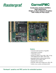
1
ACEX-4610/4620 COM Express Type 6 Carrier Board USER’S MANUAL ACROMAG INCORPORATED 30765 South Wixom Road Wixom, MI 48393-7037 U.S.A. Tel: (248) 295-0310 Fax: (248) 624-9234 Copyright 2014, Acromag, Inc., Printed in the USA. Data and specifications are subject to change without notice. 8501-005 USER’S MANUAL ACEX4610/4620 CARRIER BOARD Table of Contents 1.0 GENERAL INFORMATION.......................................................................................... 5 1.1 Intended Audience .......................................................................................................5 1.2 Preface .........................................................................................................................5 1.2.1 Trademark, Trade Name and Copyright Information .................................................................. 5 1.2.2 Class A Product Warning ............................................................................................................. 5 1.2.3 Environmental Protection Statement ......................................................................................... 5 1.3 Carrier Board Information – All Models (ACEX4610/20).................................................7 1.3.1 Ordering Information ................................................................................................................. 7 1.3.2 Key Features (All Models) ........................................................................................................... 9 1.3.3 Key Features (Models ACEX-4620 Only) .....................................................................................10 1.4 Signal Interface Products ............................................................................................ 11 1.5 Software Support ....................................................................................................... 11 1.6 References ................................................................................................................. 11 2.0 PREPARATION FOR USE........................................................................................... 12 2.1 Unpacking and Inspecting ........................................................................................... 12 2.2 Installation Considerations ......................................................................................... 13 2.3 Non-Isolation Considerations ...................................................................................... 13 2.4 Dipswitch Settings ...................................................................................................... 14 Table 2.4.1 Dipswitch Settings and Serial Port Configurations ............................................................14 Figure 2.4.1 Dipswitch Settings ..........................................................................................................15 3.0 HARDWARE INFORMATION .................................................................................. 16 3.1 Carrier Board Block Diagrams..................................................................................... 16 Fig. 3.1.1 Model ACEX-4610 Block Diagram ........................................................................................16 Fig. 3.1.2 Model ACEX-4620 Block Diagram ........................................................................................17 3.2 USB Channels .............................................................................................................. 19 Table 3.2.1 USB Channels 0-3 (USB 3.0) Connector Pinouts ...............................................................19 Table 3.2.1 USB Channels 0 to 3 (USB 3.0) Connector Pinouts (continued) ........................................20 Acromag, Inc. Tel: 248-295-0310 -1--1- http://www.acromag.com www.acromag.com USER’S MANUAL ACEX4610/4620 CARRIER BOARD Table 3.2.2 USB Channels 4 and 5 (USB 2.0) Connector Pinouts .........................................................21 3.3 SATA .......................................................................................................................... 21 Table 3.3.1 SATA 1 and SATA 2 Connectors................................................................................. 21 SATA Power Connector P17......................................................................................................... 22 Table 3.3.2 SATA Power Connector ............................................................................................. 22 Figure 3.3.1 SATA 1 (J7) and SATA 2 (J3) Locations ..................................................................... 22 Table 3.3.3 SATA 2 (J7) and SATA 3 (J3) Searay Connector Pinouts Eight optional resistors (R170 – R177) must be added to the carrier to bring this SATA signals to the Searay connector. ..................................................................................................................................................... 23 3.4 Digital Display Interface .............................................................................................. 24 Table 3.4.1 Digital Display Interface Connector Pinouts ........................................................... 24 3.5 VGA............................................................................................................................ 25 Table 3.5.1 VGA Connector Pinouts ........................................................................................... 25 3.6 eDP Embedded Display Port ....................................................................................... 26 Table 3.6.1 Embedded Display Port Connector Pinouts ......................................................................26 3.7 Gigabit Ethernet ......................................................................................................... 27 Table 3.7.1 Gigabit Ethernet Controller 0 direct from COM Express Module Connector Pinouts ........27 Table 3.7.2 Gigabit Ethernet Controller 1 Connector Pinouts .............................................................28 3.8 PCIe x4 ....................................................................................................................... 29 Table 3.8.1 PCIe x4 Connector Pinouts ...............................................................................................29 3.9 GPIO Connector Pinouts ............................................................................................. 30 Table 3.9.1 GPIO Connector Pinouts ...................................................................................................30 3.10 LPC Bus Interface Connector Pinouts ......................................................................... 30 Table 3.10.1 LPC Bus Interface Connector Pinouts ..............................................................................31 3.11 RS232/RS485 ............................................................................................................ 31 Table 3.11.1 RS232/RS422 Connector Pins ................................................................................ 31 3.12 Audio Codec ............................................................................................................. 32 Table 3.12.1 Audio Codec Connector Pinouts .....................................................................................32 3.13 SMBus and I2C bus ................................................................................................... 32 Table 3.13.1 SMBus Connector Pinouts ..............................................................................................32 3.13.2 I2C EEPROM .............................................................................................................................33 3.13.3 SMBus Voltage/Current/ Temperature Sensor ........................................................................33 Table 3.13.4 Current Reading Conversion Constants ..........................................................................33 Table 3.13.5 Voltage Reading Conversion Constants ..........................................................................33 3.14 Bottom Board Image................................................................................................. 34 Acromag, Inc. Tel: 248-295-0310 -2--2- http://www.acromag.com www.acromag.com USER’S MANUAL ACEX4610/4620 CARRIER BOARD Fig. 3.14.1 Model ACEX-4620 Bottom Board Image ............................................................................34 3.15 500 Pin Searay .......................................................................................................... 35 3.16 200 Pin Searay .......................................................................................................... 35 3.17 Dual Function miniPCIe and mSATA Slots .................................................................. 35 3.18 JTAG Program Header Connector Pinouts.................................................................. 36 Table 3.4.2: P2 and P3 Programming Connector Pinouts ....................................................................36 3.19 PMC/XMC Site 1 and Site 2 Slots ............................................................................... 37 Table 3.19.1: Table 3.19.2: Table 3.19.3: Table 3.19.4: Table 3.19.5: Table 3.19.6: Table 3.19.7: Table 3.19.7: Table 3.19.7: Table 3.19.8: Table 3.19.8: Table 3.19.8: J11/J21 PMC PCI Signal Connector Pinouts ....................................................................37 J12/J22 PMC PCI Signal Connector Pinouts ....................................................................38 J13/J23 PMC PCI Signal Connector Pinouts ....................................................................39 J14 PMC PCI/X Signal Connector Pinouts .......................................................................40 J24 PMC PCI/X Signal Connector Pinouts .......................................................................41 XMC Site 1/Site 2 Connector J15/J25 XMC Signal Pinouts .............................................42 J16 XMC Signal Connector Pinouts ................................................................................43 J16 XMC Signal Connector Pinouts (Continued) .............................................................44 J16 XMC Signal Connector Pinouts (Continued) .............................................................45 J26 XMC Site 2 Signal Connector ...................................................................................46 J26 XMC Site 2 Signal Connector (Continued) ................................................................47 J26 XMC Site 2 Signal Connector (Continued) ................................................................48 3.20 Model ACEX-4620 Top Board Image .......................................................................... 49 Fig. 3.20.1: Model ACEX-4620 Top Board Image ...................................................................................49 3.21 Cooling Fan............................................................................................................... 50 Table 3.21.1: P10 Cooling Fan Control Connector Pins ........................................................................50 Table 3.21.2: Fan Control Connector Pins ...........................................................................................50 3.22 Power Button ........................................................................................................... 50 Table 3.22.1 Power Button Connector Pin ..........................................................................................50 3.23 System Reset Button................................................................................................. 50 Table 3.23.1 System Reset Button Connector Pin ..................................................................... 50 3.24 RTC Battery .............................................................................................................. 51 3.25 PCIe Lane LED ........................................................................................................... 51 3.26 Power Supply Module............................................................................................... 51 3.26.1 Power Management ..................................................................................................................51 Table 3.26.1 Searay 500 Pin Power Supply Connector Pins .................................................................52 Table 3.26.2 Searay 200 Pin Power Supply Connector Pins .................................................................53 Acromag, Inc. Tel: 248-295-0310 -3--3- http://www.acromag.com www.acromag.com USER’S MANUAL ACEX4610/4620 CARRIER BOARD Table 3.26.3 Mezzanine Board Power Supply Connector Pins ............................................................53 3.27 COM Express Connector............................................................................................ 54 Table 3.27.1 COM Express Connector Table .......................................................................................54 4.0 SERVICE AND REPAIR ............................................................................................... 58 4.1 Service and Repair Assistance ..................................................................................... 58 4.2 Preliminary Service Procedure .................................................................................... 58 4.3 Where to Get Help...................................................................................................... 58 5.0 SPECIFICATIONS ......................................................................................................... 60 5.1 Physical ...................................................................................................................... 60 5.2 Power Requirements .................................................................................................. 63 5.3 Environmental Considerations .................................................................................... 63 5.3.1 Operating Temperature .............................................................................................................63 5.3.2 Other Environmental Requirements ..........................................................................................64 5.3.2.1 Relative Humidity .......................................................................................................... 64 5.3.2.2 Isolation ......................................................................................................................... 64 5.3.3 Vibration and Shock Standards ..................................................................................................64 5.3.3.1 ACEX-4610/20 ................................................................................................................ 64 5.3.4 EMC Directives ..........................................................................................................................64 5.4 Reliability Prediction .................................................................................................... 65 Table 5.4.1 ACEX-4620 .........................................................................................................................65 Table 5.4.2 ACEX-4610 .........................................................................................................................65 5.5 PMC/XMC Specifications ............................................................................................ 65 5.6 Other Specifications and Features ............................................................................... 65 5.6.1 5.6.2 5.6.3 5.6.4 5.6.5 5.6.6 5.6.7 5.6.8 Gigabit Ethernet ........................................................................................................................65 SATA ..........................................................................................................................................65 PCIe ...........................................................................................................................................65 mSATA/mPCIe ...........................................................................................................................66 USB 2.0 ......................................................................................................................................66 USB3.0 .......................................................................................................................................66 Audio .........................................................................................................................................66 GPIO ..........................................................................................................................................66 APPENDIX A .......................................................................................................................... 67 Acromag, Inc. Tel: 248-295-0310 -4--4- http://www.acromag.com www.acromag.com USER’S MANUAL ACEX4610/4620 CARRIER BOARD Installation of Conduction Cooling Kit ACEX-CC-01.............................................................. 67 CERTIFICATE OF VOLATILITY ........................................................................................ 74 REVISION HISTORY ............................................................................................................ 75 1.0 GENERAL INFORMATION 1.1 Intended Audience This users’ manual was written for technically qualified personnel who will be working with I/O devices using the XCOM-6400 COM Express module or any industry standard Type 6 COM Express module. It is not intended for a general, non-technical audience that is unfamiliar with computer-on-module (COM) devices and their application. 1.2 Preface The information contained in this manual is subject to change without notice, and Acromag, Inc. (Acromag) does not guarantee its accuracy. Acromag makes no warranty of any kind with regard to this material, including, but not limited to, the implied warranties of merchantability and fitness for a particular purpose. Further, Acromag assumes no responsibility for any errors that may appear in this manual and makes no commitment to update, or keep current, the information contained in this manual. No part of this manual may be copied or reproduced in any form, without the prior written consent of Acromag, 1.2.1 Trademark, Trade Name and Copyright Information © 2014 by Acromag Incorporated. All rights reserved. Acromag and Xembedded are registered trademarks of Acromag Incorporated. All other trademarks, registered trademarks, trade names, and service marks are the property of their respective owners. 1.2.2 Class A Product Warning This is a Class A product. In a domestic environment this product may cause radio interference, in which case the user may find it necessary to take adequate corrective measures. 1.2.3 Environmental Protection Statement This product has been manufactured to satisfy environmental protection requirements where possible. Many components used (structural parts, circuit boards, connectors, batteries, etc.) are capable of being recycled. Final disposition of this product after its service life must be conducted in Acromag, Inc. Tel: 248-295-0310 -5--5- http://www.acromag.com www.acromag.com USER’S MANUAL ACEX4610/4620 CARRIER BOARD accordance with applicable country, state, or local laws or regulations. Acromag, Inc. Tel: 248-295-0310 -6--6- http://www.acromag.com www.acromag.com USER’S MANUAL ACEX4610/4620 CARRIER BOARD 1.3 Carrier Board Information – All Models (ACEX4610/20) The ACEX-4610/ACEX-4620 models are Type 6 COM Express carrier boards. The ACEX-4610 model provides a COM Express interface with one PMC/XMC site, and the ACEX-4620 model provides a COM Express interface with two PMC/XMC sites. Interface to HDMI, VGA, Display Port, SATA, USB 2, USB 3, Ethernet, PCIe x4, GPIO, RS232, RS485 and Audio is provided via EDK and ACEX-FP boards also available from Acromag. 1.3.1 Ordering Information The ACEX-46XX carriers ordering options are given in the following table. Model Number ACEX-4620-LF1-4 ACEX-4610-LF-1-4 Description Temp Range Type 6 Double-Wide PMC/XMC COM -40oC to 85oC5,6 Express Carrier Lead-free Solder Type 6 Single-Wide PMC/XMC COM -40oC to 85oC5,6 Express Carrier Lead-free Solder Note 1: Model listed includes all standoffs and screws required for an air cooled application. Note 2: A conduction cooled application will require purchase of Carrier Accessory ACEX-CC-01 (Conduction Cool Kit). Note 3: An air cooled application with an Acromag XCOM-6400 will require purchase of the Active Heatsink XHSA-6400. Note 4: Air cooled applications may also require the Acromag Engineering Development Kit ACEX-4600_EDK-LF (Lead free). The platform to mount the carrier and EDK is available as Engineering Lab Development Platform ACEX-4600-DLS. Note 5: Air cooled applications have a compromise temperature range of 0oC to 70oC. Note 6: Audio Codec has a compromise temperature range of 0oC to 70oC. Acromag, Inc. Tel: 248-295-0310 -7--7- http://www.acromag.com www.acromag.com USER’S MANUAL ACEX4610/4620 CARRIER BOARD ACEX-4620-LF Model ACEX-4610-LF Model Active HeatSink XHSA-6400 Acromag, Inc. Tel: 248-295-0310 -8--8- http://www.acromag.com www.acromag.com USER’S MANUAL ACEX4610/4620 CARRIER BOARD Conduction Cool Kit ACEX-CC-01 See Appendix A for installation instructions. 1.3.2 Key Features (All Models) Acromag, Inc. Tel: 248-295-0310 Two USB 2.0 port routed to 500 pin Searay connector and two USB ports available at two mPCIe sites. Four USB 3.0 ports routed to 500 pin Searay connector. Two SATA ports routed to two SATA connectors. Three Digital Display Interface (DDI) ports are available for Display Port and HDMI/DVI interfaces. These ports are routed directly from the COM Express module to the 500-pin Searay connector. One VGA port is routed to 500 pin Searay connector. One Embedded Display (eDP) port or LVDS channel A signals can be -9--9- http://www.acromag.com www.acromag.com USER’S MANUAL ACEX4610/4620 CARRIER BOARD used and are routed to the 500 pin Searay connector. Two Gigabit LAN ports are routed to the 500 pin Searay connector. One with Ethernet signals coming direct from the COM Express and the other with Ethernet coming from an Ethernet controller. Four PCIe lanes are routed direct from COM Express to 500 pin Searay connector. Eight General Purpose I/O (4 input and 4 output) interfaces are routed from the COM Express to the 500 pin Searay connector. One Low Pin Count (LPC) bus interface is available for a range of low speed bus peripherals. This interface routes directly from the COM Express module to the 500-pin Searay connector. The carrier provides two RS232 or RS485 serial ports that are routed directly to the 500 pin Searay connector. One audio input and one audio output is routed from the carrier’s audio codec to the 500 pin Searay connector. A fan PWM TACH control for fan speed control is routed to the Searay connector. An input voltage of 10VDC-36VDC to the carrier will be required and used to generate the necessary on-board voltage rails; +/-12V, 5V and 3.3V. The 3.3V power supply will be used to generate 1.2V, 1.5V and any other required voltages using LDO (low drop-out) regulators. Two miniPCIe/mSATA slots are available on the carrier. The ACEX-46xx carrier boards support either conduction cooling or air cooling. This carrier is designed to meet extended temperature range and military grade standards for shock and vibration. 1.3.3 Key Features (Models ACEX-4620 Only) Acromag, Inc. Tel: 248-295-0310 The ACEX-4620 supports two PMC or XMC boards. The ACEX-4610 supports one PMC or XMC board. The ACEX-4620 supports a 200 pin secondary SEARAY connector to bring out PMC P4 and XMC P16 I/O signals. The increased available I/O connections of the ACEX-4620 board can provide additional I/O for required or optional features, and provide a complete test platform for the XCOM-6400. - 10 -- 10 - http://www.acromag.com www.acromag.com USER’S MANUAL ACEX4610/4620 CARRIER BOARD 1.4 Signal Interface Products The ACEX-46XX family of carrier boards is intended to be used with a custom front panel. One example is the ACEX-FP-01front panel available for interface to the ACEX-4610 carrier. The ACEX-FP-01 is designed to accept a power filter bridge board as an option. The ACEX-46XX family of carrier boards can also be used with the ACEX-EDK break-out development board. This board routes signals from the carrier’s high-density connector to individual peripheral connectors for an easy interface to I/O devices. 1.5 Software Support The ACEX-46XX family of carrier boards is intended to be used as a nonintelligent bridge between the system PCIe bus and the PMC/XMC module(s). No software is required to operate the board. However all PMC/XMC modules will require support drivers specific to your operating system. Refer to your PMC/XMC PCIe drivers. 1.6 References The following resources regarding COM Express modules, the XCOM46XX EDK board, and the Haswell© family of Intel® core processors are available for download on Acromag’s website or by contacting your sales representative. Acromag, Inc. Tel: 248-295-0310 COM Express Module Base Specification Rev. 2.1 http://www.acromag.com APTIOTM Core BIOS Manual (for Acromag® Products featuring the Intel® 4th Generation “Haswell” Core Processor Family) http://www.acromag.com XCOM46XX Engineering Design Kit (EDK) Board http://www.acromag.com - 11 -- 11 - http://www.acromag.com www.acromag.com USER’S MANUAL ACEX4610/4620 CARRIER BOARD 2.0 PREPARATION FOR USE IMPORTANT PERSONAL AND PRODUCT SAFETY CONSIDERATIONS It is very important for the user to consider the possible safety implications of power, wiring, component, sensor, or software failures in designing any type of control or monitoring system. This is especially important where personal injury or the loss of economic property or human life is possible. It is important that the user employ satisfactory overall system design. It is understood and agreed by the Buyer and Acromag that this is the Buyer's responsibility. WARNING: This board utilizes static sensitive components and should only be handled at a static-safe workstation. This product is an electrostatic sensitive device and is packaged accordingly. Do not open or handle this product except at an electrostatic-free workstation. Additionally, do not ship or store this product near strong electrostatic, electromagnetic, magnetic, or radioactive fields unless the device is contained within its original manufacturer’s packaging. Be aware that failure to comply with these guidelines will void the Acromag Limited Warranty. 2.1 Unpacking and Inspecting Upon receipt of this product, inspect the shipping carton for evidence of mishandling during transit. If the shipping carton is badly damaged or water stained, request that the carrier's agent be present when the carton is opened. If the carrier's agent is absent when the carton is opened and the contents of the carton are damaged, keep the carton and packing material for the agent's inspection. For repairs to a product damaged in shipment, refer to the Acromag Service Policy to obtain return instructions. It is suggested that salvageable shipping cartons and packing material be saved for future use in the event the product must be shipped. This board is physically protected with packing material and electrically protected with an anti-static bag during shipment. However, it is recommended that the board be visually inspected for evidence of mishandling prior to applying power. Acromag, Inc. Tel: 248-295-0310 - 12 -- 12 - http://www.acromag.com www.acromag.com USER’S MANUAL ACEX4610/4620 CARRIER BOARD 2.2 Installation Considerations Refer to the specifications section for loading and power requirements. Be sure that the system power supplies are able to accommodate the power requirements of the system boards, plus the installed Acromag board, within the voltage tolerances specified. IMPORTANT: Adequate air circulation is required! In an air cooled assembly, adequate air circulation must be provided to prevent a temperature rise above the maximum operating temperature and to prolong the life of the electronics. If the installation is in an industrial environment and the board is exposed to environmental air, careful consideration should be given to air-filtering. In a conduction cooled assembly, adequate thermal conduction must be provided to prevent a temperature rise above the maximum operating temperature. 2.3 Non-Isolation Considerations The board is non-isolated, since there is electrical continuity between the PCIe bus and COM Express module grounds. As such, the field I/O connections are not isolated from the system. Care should be taken in designing installations without isolation to avoid noise pickup and ground loops caused by multiple ground connections. Acromag, Inc. Tel: 248-295-0310 - 13 -- 13 - http://www.acromag.com www.acromag.com USER’S MANUAL ACEX4610/4620 CARRIER BOARD 2.4 Dipswitch Settings Shown in Figure 2.4.1 and Table 2.4.1 below are the dipswitch settings and serial port configurations. Dipswitch board location is shown in figure 3.14.1 in bottom right hand location. Table 2.4.1 Dipswitch Settings and Serial Port Configurations Bold indicates default setting 1 21 31 4 5 6 7 8 ON J15 JTAG voltage = 2.5Vdc OFF J15 JTAG voltage = 3.3Vdc ON J25 JTAG voltage = 2.5Vdc OFF J25 JTAG voltage = 3.3Vdc ON J25 MPRESENT#, Signal low , Enable (XMC Site 2) OFF J25 MPRESENT# , Signal High, Disable (XMC Site 2) ON SER_MODE0 (see Serial Port Configuration below) OFF SER_MODE0 (see Serial port configuration below) ON SER_MODE1 (see Serial Port Configuration below) OFF SER_MODE1 (see Serial Port Configuration below) ON mPCIe/mSATA site 1 = mPCIe enabled OFF mPCIe/mSATA site 1 = mSATA enabled ON mPCIe/mSATA site 2 = mPCIe enabled OFF mPCIe/mSATA site 2 = mSATA enabled ON PCI_SEL_100 = 25, 50, 100MHz OFF PCI_SEL_100 = 33, 66, 133MHz Note 1: Dipswitches 2 and 3 do not apply to the ACEX4610 models Serial Port Configuration Dual RS-232 Acromag, Inc. Tel: 248-295-0310 - 14 -- 14 - SER_Mode0 0 SER_Mode1 0 http://www.acromag.com www.acromag.com USER’S MANUAL ACEX4610/4620 CARRIER BOARD COM0: RS-232 / COM1:RS-485 Dual RS-485 Low Power Shutdown 0 1 1 1 0 1 J1 5 JT AG J2 5 JT AG J2 5 M P SE RES R EN M od T# SE e1 R M od m e0 PC Ie /m m PC SAT Ie A /m Si SA te 1 TA PC Si I_ te SE 2 L_ 10 0 Figure 2.4.1 Dipswitch Settings 1 2 3 4 5 6 7 8 ON Note 1: Dipswitch 2 and 3 do not apply to the ACEX4610 models XMC and PMC Expansion Sites XMC can be used in both Site 1 and Site 2. PMC can also be used in both Site 1 and Site 2. However if an XMC is used with a PMC module, the XMC must be in Site 1 and the PMC must be in Site 2. See Figure 3.14.1 for Site 1 and Site 2 locations. If the PMC in Site 2 is not recognized, check Dipswitch setting 3 and make sure it is set to off. Acromag, Inc. Tel: 248-295-0310 - 15 -- 15 - http://www.acromag.com www.acromag.com USER’S MANUAL ACEX4610/4620 CARRIER BOARD 3.0 HARDWARE INFORMATION 3.1 Carrier Board Block Diagrams The block diagrams for the ACEX-46XX family of carrier boards are shown below in Figs. 3.1.1 and 3.1.2. These may be a helpful reference as you review the connector pin out tables in this section. Fig. 3.1.1 Model ACEX-4610 Block Diagram SATA Connector 1 SATA Connector 2 FAN Power Button Sys Reset Button SATA I2C Bus SATA EEPROM USB 2.0 (x2) USB 3.0 (x4) DDI(x3) Current Voltage Sensor Thermal Sensor VGA SMBus eDP Gigabit Ethernet Gigabit Ethernet Battery Ethernet Controller Intel 82574 PCIe x1 +1.5V to mPCIE/mSATA PCIe x4 PCIe x1 COM Express Connectors GPIO SATA0 PCIe/SATA MUX PI2DBS6212 mPCIE/mSATA Site 1 PCIe/SATA MUX PI2DBS6212 mPCIE/mSATA Site 2 LPC BUS 500 Pin Searay Connector USB 6 RS232 Or RS422 Exar Serial Tran SP336 Line In Line Out Serial COM x2 Audio Codec ALC892 PCIe x1 SATA1 HDA Audio USB 7 PCIe Clock Driver PI6C20800S2I PCIe REF CLK Fan PWM TACH Control Power Button PCIe REF CLKs Out PCIe (PEG) x4 (Not Used) System Reset Button COM Express Reset Out PCIe (PEG) x4 +1.2V to TSi384 PCIe (PEG) x8 PCIe to PCI Bridge TSi384 +5V +12V J14 I/O (64bit) J16 I/O (x8 PCIe and SIO 36bit) PCI Bus XMC PMC Site 1 +3.3V, +5V, and +12V -12V 10-36VDCin DC/DC Power Board Acromag, Inc. Tel: 248-295-0310 +3.3V - 16 -- 16 - http://www.acromag.com www.acromag.com USER’S MANUAL ACEX4610/4620 CARRIER BOARD Fig. 3.1.2 Model ACEX-4620 Block Diagram Acromag, Inc. Tel: 248-295-0310 - 17 -- 17 - http://www.acromag.com www.acromag.com USER’S MANUAL ACEX4610/4620 CARRIER BOARD SATA Connector 1 SATA Connector 2 FAN Power Button Sys Reset Button SATA I2C Bus SATA USB 2.0 (x2) EEPROM USB 3.0 (x4) DDI(x3) Current Voltage Sensor Thermal Sensor VGA SMBus eDP Gigabit Ethernet Gigabit Ethernet Battery Ethernet Controller Intel 82574 PCIe x1 +1.5V to mPCIE/mSATA PCIe x4 PCIe x1 COM Express Connectors GPIO SATA0 PCIe/SATA MUX PI2DBS6212 mPCIE/mSATA Site 1 PCIe/SATA MUX PI2DBS6212 mPCIE/mSATA Site 2 LPC BUS 500 Pin Searay Connector USB 6 RS232 Or RS422 Exar Serial Tran SP336 Line In Line Out Serial COM x2 Audio Codec ALC892 PCIe x1 SATA1 HDA Audio USB 7 PCIe REF CLK Fan PWM TACH Control Power Button PCIe Clock Driver PI6C20800S2I PCIe REF CLKs Out PCIe (PEG) x4 System Reset Button COM Express Reset Out PCIe (PEG) x4 PCIe Mux PI3PCIE3422 PCIe (PEG) x8 PCIe x4 +1.2V to TSi384 PCIe x4 PCIe to PCI Bridge TSi384 +5V +12V J14 I/O (64bit) J16 I/O (x8 PCIe and SIO 36bit) PCIe x4 PCI Bus PMC/XMC Site 1 PMC/XMC Site 2 +3.3V, +5V, and +12V 10-36VDCin +3.3V, +5V, and +12V -12V DC/DC Power Board +3.3V 10-36VDCin 200 Pin Searay Connector J24 I/O (64bit) J26 I/O (x8 PCIe and SIO 36bit) Acromag, Inc. Tel: 248-295-0310 - 18 -- 18 - http://www.acromag.com www.acromag.com USER’S MANUAL ACEX4610/4620 CARRIER BOARD 3.2 USB Channels Four channels of USB 3.0 are available on USB channels 0 to 3 which are routed to the 500 pin Searay connector. In addition, two channels of USB 2.0 are available on channels 4 and 5 which are also routed to the 500 pin Searay connector. Two additional USB channels 6 and 7 are available on the mPCIe sites 1 and 2. Table 3.2.1 USB Channels 0-3 (USB 3.0) Connector Pinouts USB 3.0 Signal Searay 500Pin Description USB0_+5V1 A21 USB Channel 0 Positive 5V from Carrier USB0_P B21 USB Channel 0 Differential Pair "USB0+" USB0_N B22 USB Channel 0 Differential Pair "USB0-" USB1_+5V1 C21 USB Channel 1 Positive 5V from Carrier USB1_P D21 USB Channel 1 Differential Pair "USB0+" USB1_N D22 USB Channel 1 Differential Pair "USB0-" USB2_+5V1 E21 USB Channel 2 Positive 5V from Carrier USB2_P F21 USB Channel 2 Differential Pair "USB0+" USB2_N F22 USB Channel 2 Differential Pair "USB0-" USB3_P B25 USB Channel 3 Differential Pair "USB0+" USB3_N B26 USB Channel 3 Differential Pair "USB0-" USB3_+5V1 A25 USB Channel 3 Positive 5V from Carrier Note 1: Carrier board ground signals provided on Searay connector are given in Tables 3.26.1 and 3.26.2. The current monitoring and protection provided by the ACEX-4610/20 carrier boards is summarized below: USB channels 0 to 3 are USB 3.0, and are current monitored and protected up to 1A each. Acromag, Inc. Tel: 248-295-0310 - 19 -- 19 - http://www.acromag.com www.acromag.com USER’S MANUAL ACEX4610/4620 CARRIER BOARD USB channels 4 and 5 are USB 2.0, and are current monitored and protected up to 0.5A each. USB channels 6 and 7, which go to the mPCIe sites 1 and 2, require no current monitoring or protection. Table 3.2.1 USB Channels 0 to 3 (USB 3.0) Connector Pinouts (continued) Acromag, Inc. Tel: 248-295-0310 USB 3.0 Signal Searay 500Pin Description USB0_SSRX_P J47 USB Channel 0 SuperSpeed Receive Positive USB0_SSRX_N J48 USB Channel 0 SuperSpeed Receive Negative USB0_SSTX_P K49 USB Channel 0 SuperSpeed Transmit Positive USB0_SSTX_N K50 USB Channel 0 SuperSpeed Transmit Negative USB1_SSRX_P G47 USB Channel 1 SuperSpeed Receive Positive USB1_SSRX_N G48 USB Channel 1 SuperSpeed Receive Negative USB1_SSTX_P H49 USB Channel 1 SuperSpeed Transmit Positive USB1_SSTX_N H50 USB Channel 1 SuperSpeed Transmit Negative USB2_SSRX_P J43 USB Channel 2 SuperSpeed Receive Positive USB2_SSRX_N J44 USB Channel 2 SuperSpeed Receive Negative USB2_SSTX_P K45 USB Channel 2 SuperSpeed Transmit Positive USB2_SSTX_N K46 USB Channel 2 SuperSpeed Transmit Negative USB3_SSRX_P G43 USB Channel 3 SuperSpeed Receive Positive USB3_SSRX_N G44 USB Channel 3 SuperSpeed Receive Negative USB3_SSTX_P H45 USB Channel 3 SuperSpeed Transmit Positive USB3_SSTX_N H46 USB Channel 3 SuperSpeed Transmit Negative - 20 -- 20 - http://www.acromag.com www.acromag.com USER’S MANUAL ACEX4610/4620 CARRIER BOARD Table 3.2.2 USB Channels 4 and 5 (USB 2.0) Connector Pinouts USB 2.0 Signal Searay 500Pin Description USB4_+5V1 A29 USB Channel 4 Positive 5V from Carrier USB4_P B29 USB Channel 4 Differential Pair "USB4+" USB4_N B30 USB Channel 4 Differential Pair "USB4-" USB5_+5V1 B31 USB Channel 5 Positive 5V from Carrier USB5_P C31 USB Channel 5 Differential Pair "USB5+" USB5_N C32 USB Channel 5 Differential Pair "USB5-" Note 1: Carrier board ground signals provided on Searay connector are given in Tables 3.26.1 and 3.26.2. 3.3 SATA The carrier references SATA ports as they are provided by the COM Express. It is SATA ports 2 and 3 from the COM Express that are routed to carrier on board SATA connectors 1 (J7) and 2 (J3) respectively as seen in figure 3.3.1. SATA ports 2 and 3 can optionally be routed to the 500 pin Searay connector. Two additional SATA ports 0 and 1 are available on the mSATA sites 1 and 2 respectively. The SATA connector is a seven conductor header. There are three grounds and four active data lines in two pairs. SATA 1 is labeled J7 on the carrier and SATA 2 is labeled J3 on the carrier. The carrier connector is Molex 67800-8005 socket. Table 3.3.1 SATA 1 and SATA 2 Connectors Acromag, Inc. Tel: 248-295-0310 Pin Number Signal Name Function 1 GND Ground 2 SATA_TX_P Transmit + 3 SATA_TX_N Transmit - 4 GND Ground - 21 -- 21 - http://www.acromag.com www.acromag.com USER’S MANUAL ACEX4610/4620 CARRIER BOARD SATA Power Connector P17 5 SATA_RX_N Receive - 6 SATA_RX_P Receive + 7 GND Ground The SATA power connector is a 4 pin conductor header. The SATA power connector is labeled P17 on the carrier. There is one ground and two power signals 5V, and +12V available on this connector. All power supplies are independently fused with a PolySwitch resettable device. At +12V the fuse is rated to 0.5A. The +5V is rated to 1.1A. A +3.3V supply is optionally available on Pin 3. Fuse F2 is currently open on the carrier and must be installed to bring +3.3V power to pin 3 of this connector. This connector is a Molex 470531000 header. Table 3.3.2 SATA Power Connector Pin Description Number Pin Description Number GND 1 +12V 2 +3.3V (OPEN) 3 +5V 4 Figure 3.3.1 SATA 1 (J7) and SATA 2 (J3) Locations Acromag, Inc. Tel: 248-295-0310 - 22 -- 22 - http://www.acromag.com www.acromag.com USER’S MANUAL ACEX4610/4620 CARRIER BOARD Table 3.3.3 SATA 2 (J7) and SATA 3 (J3) Searay Connector Pinouts Eight optional resistors (R170 – R177) must be added to the carrier to bring this SATA signals to the Searay connector. Acromag, Inc. Tel: 248-295-0310 SATA Signal Searay 500Pin Description SATA_RX2_P J40 SATA2 Receive Differential Pair Positive SATA_RX2_N J39 SATA2 Receive Differential Pair Negative SATA_TX2_P K42 SATA2 Transmit Differential Pair Positive SATA_TX2_N K41 SATA2 Transmit Differential Pair Negative SATA_RX3_P G40 SATA3 Receive Differential Pair Positive SATA_RX3_N G39 SATA3 Receive Differential Pair Negative SATA_TX3_P H42 SATA3 Transmit Differential Pair Positive SATA_TX3_N H41 SATA3 Transmit Differential Pair Negative - 23 -- 23 - http://www.acromag.com www.acromag.com USER’S MANUAL ACEX4610/4620 CARRIER BOARD 3.4 Digital Display Interface Three Digital Display Interface (DDI) ports are available for Display Port and HDMI/DVI interfaces. DDI[1] can also support the SDVO interface. See Table 3.4.1 below for a summary of the DDI connectors. Table 3.4.1 Digital Display Interface Connector Pinouts Acromag, Inc. Tel: 248-295-0310 DDI Signal Searay 500 Pin Description DPB_CTRL_AUX_P F38 DP AUX+ or HDMI/DVI I2C Ctrl Clk DPB_CTRL_AUX_N F37 DP AUX- or HDMI/DVI I2C Data DPB_AUX_SEL D36 Selects function of DPD_CTRL_AUX_P/N signals DDB_HPD D37 Hot Plug Detect DPB_TX0_P H38 Positive Differential Pair DPB_TX0_N H37 Negative Differential Pair DPB_TX1_P K38 Positive Differential Pair DPB_TX1_N K37 Negative Differential Pair DPB_TX2_P J36 Positive Differential Pair DPB_TX2_N J35 Negative Differential Pair DPB_TX3_P G36 Positive Differential Pair DPB_TX3_N G35 Negative Differential Pair DPC_CTRL_AUX_P E32 DP AUX+ or HDMI/DVI I2C Ctrl Clk DPC_CTRL_AUX_N E31 DP AUX- or HDMI/DVI I2C Data DPC_AUX_SEL B32 Selects function of DPD_CTRL_AUX_P/N signals DPC_HPD C33 Hot Plug Detect DPC_TX0_P D30 Positive Differential Pair DPC_TX0_N D29 Negative Differential Pair DPC_TX1_P F30 Positive Differential Pair DPC_TX1_N F29 Negative Differential Pair DPC_TX2_P E28 Positive Differential Pair DPC_TX2_N E27 Negative Differential Pair - 24 -- 24 - http://www.acromag.com www.acromag.com USER’S MANUAL ACEX4610/4620 CARRIER BOARD Table 3.4.1 Digital Display Interface Connector Pinouts (continued) DDI Signal Searay 500 Pin Description DPC_TX3_P C28 Positive Differential Pair DPC_TX3_N C27 Negative Differential Pair DPD_CTRL_AUX_P F34 DP AUX+ or HDMI/DVI I2C Ctrl Clk DPD_CTRL_AUX_N F33 DP AUX- or HDMI/DVI I2C Data DPD_AUX_SEL D33 Selects function of DPD_CTRL_AUX_P/N signals DPD_HPD D34 Hot Plug Detect DPD_TX0_P H34 Positive Differential Pair DPD_TX0_N H33 Negative Differential Pair DPD_TX1_P K34 Positive Differential Pair DPD_TX1_N K33 Negative Differential Pair DPD_TX2_P J32 Positive Differential Pair DPD_TX2_N J31 Negative Differential Pair DPD_TX3_P G32 Positive Differential Pair DPD_TX3_N G31 Negative Differential Pair 3.5 VGA An analog RGB interface is available for CRT monitor and DDC support. Table 3.5.1 below summarizes the VGA connectors. Table 3.5.1 VGA Connector Pinouts Acromag, Inc. Tel: 248-295-0310 VGA Signal Searay 500 pin Description VGA_RED B44 Red for monitor VGA_GRN B45 Green for monitor VGA_BLU 500 B43 Pin Blue for monitor VGA_HSYNC D45 Horizontal sync VGA_VSYNC D44 Vertical sync VGA_I2C_CK D46 DDC clock line - 25 -- 25 - http://www.acromag.com www.acromag.com USER’S MANUAL ACEX4610/4620 CARRIER BOARD VGA_I2C_DAT C46 DDC data line 3.6 eDP Embedded Display Port One Embedded Display port or LVDS channel A signals can be alternatively used on this eDP (refer to Table 3.6.1 below). Table 3.6.1 Embedded Display Port Connector Pinouts Acromag, Inc. Tel: 248-295-0310 eDP Signal Searay 500 Pin Description EDP_TX0_P (LVDS_A2+) E24 Positive Differential Pair EDP_TX0_N (LVDS_A2-) E23 Negative Differential Pair EDP_TX1_P (LVDS_A1+) D26 Positive Differential Pair EDP_TX1_N (LVDS_A1-) D25 Negative Differential Pair EDP_TX2_P (LVDS_A0+) F26 Positive Differential Pair EDP_TX2_N (LVDS_A0-) F25 Negative Differential Pair EDP_TX3_P (LVDS_CK+) C24 Positive Differential Pair EDP_TX3_N (LVDS_CK-) C23 Negative Differential Pair EDP_HPD A26 Hot Plug Detection EDP_AUX_P (LVDS_I2C_CK) H22 eDP AUX+ EDP_AUX_N (LVDS_I2C_DAT H21 eDP AUX- EDP_VDDEN (LVDS_VDD EN) C22 eDP Power Enable EDP_BKLTEN (LVDS BKLT EN) A28 eDP Backlight Enable EDP_BKLTCTL (LVDS BKLT CTRL) A27 eDP Backlight Brightness Control - 26 -- 26 - http://www.acromag.com www.acromag.com USER’S MANUAL ACEX4610/4620 CARRIER BOARD 3.7 Gigabit Ethernet Two Gigabit LAN ports are routed to the 500 pin Searay connector. One with Ethernet signals coming direct from the COM Express. The second Gigabit Ethernet channels is provided using a x1 PCIe lane from the Com Express to a carrier Intel 82574 PCIe PHY Ethernet controller. The Intel 82574 Ethernet Controller uses PCIe lane 5 from the Com Express module. Table 3.7.1 Gigabit Ethernet Controller 0 direct from COM Express Module Connector Pinouts Acromag, Inc. Tel: 248-295-0310 Gigabit Ethernet Signal Searay 500Pin Description GBE0_MDI3_P A47 Controller 0 from Module - MDI Differential Pair 3 Positive GBE0_MDI3_N A48 Controller 0 from Module - MDI Differential Pair 3 Negative GBE0_MDI2_P B47 Controller 0 from Module - MDI Differential Pair 2 Positive GBE0_MDI2_N B48 Controller 0 from Module - MDI Differential Pair 2 Negative GBE0_MDI1_P C47 Controller 0 from Module - MDI Differential Pair 1 Positive GBE0_MDI1_N C48 Controller 0 from Module - MDI Differential Pair 1 Negative GBE0_MDI0_P D47 Controller 0 from Module - MDI Differential Pair 0 Positive GBE0_MDI0_N D48 Controller 0 from Module - MDI Differential Pair 0 Negative GBE0_L1000# E47 Controller 0 from Module - 1000 Mb/s Link Indicator GBE0_LINK# E49 Controller 0 from Module - Link Indicator GBE0_ACT# F49 Controller 0 from Module - Activity Indicator - 27 -- 27 - http://www.acromag.com www.acromag.com USER’S MANUAL ACEX4610/4620 CARRIER BOARD Table 3.7.2 Gigabit Ethernet Controller 1 Connector Pinouts Acromag, Inc. Tel: 248-295-0310 Gigabit Ethernet Signal Searay 500Pin Description GBE1_MDI3_P A49 Controller 1 from Carrier - MDI Differential Pair 3 Positive GBE1_MDI3_N A50 Controller 1 from Carrier - MDI Differential Pair 3 Negative GBE1_MDI2_P B49 Controller 1 from Carrier - MDI Differential Pair 2 Positive GBE1_MDI2_N B50 Controller 1 from Carrier - MDI Differential Pair 2 Negative GBE1_MDI1_P C49 Controller 1 from Carrier - MDI Differential Pair 1 Positive GBE1_MDI1_N C50 Controller 1 from Carrier - MDI Differential Pair 1 Negative GBE1_MDI0_P D49 Controller 1 from Carrier - MDI Differential Pair 0 Positive GBE1_MDI0_N D50 Controller 1 from Carrier - MDI Differential Pair 0 Negative GBE1_1V9 E48 External 1.9V Reference Voltage from Carrier for Gigabit Ethernet Controller 1 GBE1_LINK# E50 Controller 1 from Carrier - Link Indicator GBE1_ACT# F50 Controller 1 from Carrier Activity Indicator - 28 -- 28 - http://www.acromag.com www.acromag.com USER’S MANUAL ACEX4610/4620 CARRIER BOARD 3.8 PCIe x4 Four PCIe lanes are routed directly from COM Express to the 500 pin Searay connector Table 3.8.1 PCIe x4 Connector Pinouts Acromag, Inc. Tel: 248-295-0310 PCIe Signal Searay 500 Pin Description PCIE0_RX_P G24 PCI Express Lane 0 Receive Differential Pair Positive PCIE0_RX_N G23 PCI Express Lane 0 Receive Differential Pair Negative PCIE0_TX_P H26 PCI Express Lane 0 Transmit Differential Pair Positive PCIE0_TX_N H25 PCI Express Lane 0 Transmit Differential Pair Negative PCIE1_RX_P J24 PCI Express Lane 1 Receive Differential Pair Positive PCIE1_RX_N J23 PCI Express Lane 1 Receive Differential Pair Negative PCIE1_TX_P K25 PCI Express Lane 1 Transmit Differential Pair Positive PCIE1_TX_N K26 PCI Express Lane 1 Transmit Differential Pair Negative PCIE2_RX_P G28 PCI Express Lane 2 Receive Differential Pair Positive PCIE2_RX_N G27 PCI Express Lane 2 Receive Differential Pair Negative PCIE2_TX_P H30 PCI Express Lane 2 Transmit Differential Pair Positive PCIE2_TX_N H29 PCI Express Lane 2 Transmit Differential Pair Negative PCIE3_RX_P J28 PCI Express Lane 3 Receive Differential Pair Positive PCIE3_RX_N J27 PCI Express Lane 3 Receive Differential Pair Negative PCIE3_TX_P K30 PCI Express Lane 3 Transmit Differential Pair Positive PCIE3_TX_N K29 PCI Express Lane 3 Transmit Differential Pair Negative - 29 -- 29 - http://www.acromag.com www.acromag.com USER’S MANUAL ACEX4610/4620 CARRIER BOARD 3.9 GPIO Connector Pinouts Eight General Purpose I/O (4 input and 4 output) interfaces are available. See Table 3.9.1 below for a summary of the GPIO connectors. Table 3.9.1 GPIO Connector Pinouts GPIO Signal Searay 500Pin Description GPI_0 D19 General Purpose Input 0 GPI_1 C20 General Purpose Input 1 GPI_2 B19 General Purpose Input 2 GPI_3 B20 General Purpose Input 3 GPO_0 B23 General Purpose Output 0 GPO_1 B24 General Purpose Output1 GPO_2 E20 General Purpose Output 2 GPO_3 D20 General Purpose Output 3 3.10 LPC Bus Interface Connector Pinouts The Low Pin Count (LPC) bus interface is available for a range of low speed bus peripherals. This interface routes directly from the COM Express module to the 500-pin Searay connector. The LPC bus can provide legacy PC I/O functions, including PS2 keyboard and mouse ports, serial and parallel ports, and a floppy interface. Table 3.10.1 below summarizes the LPC bus connectors. Acromag, Inc. Tel: 248-295-0310 - 30 -- 30 - http://www.acromag.com www.acromag.com USER’S MANUAL ACEX4610/4620 CARRIER BOARD LPC Interface Table 3.10.1 LPC Bus Interface Connector Pinouts Searay 500 Pin Description LPC_AD0 LPC_AD1 LPC_AD2 LPC_AD3 E46 E45 F46 F45 LPC multiplexed address, command and data bus LPC_FRAME# F43 LPC frame indicates the start of a LPC cycle LPC_DRQ0# (PCH_DRQ0#) D42 LPC serial DMA request LPC_DRQ1# (PCH_DRQ1#) D41 LPC serial DMA request LPC_SERIRQ (INT_SERIRQ) E42 LPC serial interrupt LPC_CLK (CK_PCI_LPC) F42 LPC clock output 3.11 RS232/RS485 The carrier provides two RS232 or RS485 serial ports that are routed directly to the 500 pin Searay connector. See the dip switch selection section 2.4 for the serial port configuration options. Table 3.11.1 RS232/RS422 Connector Pins Acromag, Inc. Tel: 248-295-0310 RS232/RS422 Signal Searay 500 Pin Description UART_TX0_P B33 General Purpose Serial Port 0 from Carrier Transmitter Positive UART_TX0_N B34 General Purpose Serial Port 0 from Carrier Transmitter Negative UART_RX0_P B35 General Purpose Serial Port 0 from Carrier Receiver Positive UART_RX0_N B36 General Purpose Serial Port 0 from Carrier Receiver Negative UART_TX1_P B37 General Purpose Serial Port 1 from Carrier Transmitter Positive UART_TX1_N B38 General Purpose Serial Port 1 from Carrier Transmitter Negative UART_RX1_P B39 General Purpose Serial Port 1 from Carrier Receiver Positive UART_RX1_N B40 General Purpose Serial Port 1 from Carrier Receiver Negative - 31 -- 31 - http://www.acromag.com www.acromag.com USER’S MANUAL ACEX4610/4620 CARRIER BOARD 3.12 Audio Codec One audio input and one audio output is routed from the carrier’s audio codec to the 500 pin Searay connector. Table 3.12.1 Audio Codec Connector Pinouts Audio Codec Signal Searay 500 Pin Description LINE-IN_R A44 Right Channel Audio Line In from CODEC on Carrier LINE-IN_L A45 Left Channel Audio Line In from CODEC on Carrier LINE-OUT_R A42 Right Channel Audio Line Out from CODEC on Carrier LINE-OUT_L B42 Left Channel Audio Line Out from CODEC on Carrier 3.13 SMBus and I2C bus The SMBus is optionally routed from the COM Express to the 500 pin Searay connector. Resistors R18 and R19 on the ACEX-4620 or R48 and R49 on the ACEX-4610 normally open must be installed to allow connection of the SMBus to the Searay connector. If these resistors are required for your application, it is strongly recommended that the board be returned to Acromag for installation of these zero ohm resistors. Table 3.13.1 SMBus Connector Pinouts SMBus Signal Searay 500 Pin Description SMB_DATA E39 System Management Bus Bidirectional Data Line SMB_CLK E40 System Management Bus Bidirectional Clock Line SMB_ALERT# E41 System Management Bus Alert Signal SMBus is also brought out to the P2 connector on the carrier. The SMB Clock is available on pin 1 of P2 and the SMB Data is available on pin 12 of P2. The P2 connector is a Molex 2x7 header (Molex part number 87832-1420). The location of the P2 connector is shown in Figure 3.14.1 and is labeled “XMC Site 1 JTAG Connector”. Acromag, Inc. Tel: 248-295-0310 - 32 -- 32 - http://www.acromag.com www.acromag.com USER’S MANUAL ACEX4610/4620 CARRIER BOARD 3.13.2 I2C EEPROM There is one EEPROM device U2700 on the I2C bus. Information such as board module number, part number and revision level can be stored in this location. Address line A0 to A2 are pulled to logic high, placing the device at address 0xAE (A6-A3 = 1010b for EEPROM devices). 3.13.3 SMBus Voltage/Current/ Temperature Sensor This device U3800 is on the SMBus and will report board temperature as well as current and voltages for the +12, +5, and +3.3 volt supplies. Figure 3.14.1 shown below shows the location of this device under the PMC/XMC site 1. Address lines A0 to A2 are pulled to logic high. Table 3.13.4 Current Reading Conversion Constants The 12V_Current, 5v_Current, and 3p3v_Current signals are routed to U3800 an I2C analog to digital converter. The voltages present on these signals can be converted to a current reading in software with use of the following constants. For example voltage read at LTC2991 port V3 multiplied by 2.3 will give the 12volt supply current reading in amps. Table 3.13.5 Voltage Reading Conversion Constants Signal Constant LTC2991 Port 12v_Current 2.3 V3 5v_Current 2.5 V5 3p3v_Current 2.7 V7 Other LTC2991 ports are used to provide a reading of the voltages of the input voltage, 12v, 5v, and 3.3v supplies. For example, the voltage read at the LTC2991 port V4 multiplied by 4.74 will give the 12volt supply voltage. Acromag, Inc. Tel: 248-295-0310 Signal Constant LTC2991 Port Input Voltage 8.32 V1 and V2 12 Volt Supply 4.74 V4 5 Volt Supply 2.0 V6 3.3 Volt Supply 1.0 V8 - 33 -- 33 - http://www.acromag.com www.acromag.com USER’S MANUAL ACEX4610/4620 CARRIER BOARD 3.14 Bottom Board Image Fig. 3.14.1 Model ACEX-4620 Bottom Board Image Acromag, Inc. Tel: 248-295-0310 - 34 -- 34 - http://www.acromag.com www.acromag.com USER’S MANUAL ACEX4610/4620 CARRIER BOARD 3.15 500 Pin Searay The ACEX-4620/10 models all use one high speed 500 SEARAY connector that is shown in the picture above. This 500-pin connector can interface with ACEX-4600-EDK and other custom I/O panels. The carrier passes the peripheral signals from the COM Express CPU through this connector along with the PMC/XMC Site 1 Rear I/O signals. 3.16 200 Pin Searay The smaller SEARAY connector is a 200-pin connector that is used to interface with the ACEX-4620 double-wide COM Express Carrier. The ACEX-4620 carrier passes the PMC/XMC Site 2 Rear I/O signals through this connector to the high-speed connectors shown in the diagram above. The single-wide ACEX4610 carriers does not contain a second PMC/XMC Site and therefore does not make a connection with the 200-pin SEARAY connector. 3.17 Dual Function miniPCIe and mSATA Slots The carrier has two dual function miniPCIe/mSATA slots. Each of the dual function slots can accept either a mini PCIe module or an mSATA module. These slots use a multiplexer circuit that allows for the selection between connecting the PCIe or SATA lane. A USB 2.0 port is also provided as defined in the mini PCIe specification. The mini PCIe/mSATA slots are designed for full length modules. With an adapter a half-length module can alternatively be installed. Board 6mm standoffs and M2.5 screws are provided with the carrier for installation of mini PCIe/mSATA modules. See image 3.14.1 for the mini PCIe and mSATA site 1 and 2 locations. Acromag, Inc. Tel: 248-295-0310 - 35 -- 35 - http://www.acromag.com www.acromag.com USER’S MANUAL ACEX4610/4620 CARRIER BOARD 3.18 JTAG Program Header Connector Pinouts Some PMC/XMC modules may utilize JTAG connections for FPGA programming or Chipscope debug activities. Individual JTAG connections are available for each site through the use of a Molex 2x7 header (Molex part number 87832-1420). Acromag XMC FPGA boards can be configured to route the JTAG programming signals through the XMC P15 [XMC site 1] connector and XMC P25 [XMC site 2] connector. The location of the P2 and P3 JTAG programming headers on the carrier board are shown in Fig. 3.14.1. The P2 JTAG connector connects to PMC/XMC in XMC site 1 on an ACEX-4610 or ACEX-4620 carrier board. The P3 JTAG connector connects to the PMC/XMC in XMC site 2 on an ACEX4620 carrier board. VREF can be set to either 2.5V or 3.3V. Setting “On” switch 1 of Dipswitch DIP1A selects 2.5V for VREF to XMC/PMC slot 1. Setting “On” switch 2 of Dip-switch DIP1A selects 2.5V for VREF to XMC/PMC slot 2. The switch left “Off” selects 3.3V. Please refer to Table 2.4.1 for more information on the Dip-switch settings and descriptions. Pin Description SMB CLK2 GND GND GND GND GND NC1 Table 3.4.2: P2 and P3 Programming Connector Pinouts Number 1 3 5 7 9 11 13 Pin Description VREF TMS TCK TDO TDI SMB DATA2 NC1 Number 2 4 6 8 10 12 14 Notes: 1. NC – Not Connected 2. The P2 only has the SMB CLK and SMB DATA on pins 1 and 12. On the P3 pins 1 and 12 are NC. Acromag, Inc. Tel: 248-295-0310 - 36 -- 36 - http://www.acromag.com www.acromag.com USER’S MANUAL ACEX4610/4620 CARRIER BOARD 3.19 PMC/XMC Site 1 and Site 2 Slots XMC and PMC Expansion Sites XMC can be used in both Site 1 and Site 2. PMC can also be used in both Site 1 and Site 2. However if an XMC is used with a PMC module, the XMC must be in Site 1 and the PMC must be in Site 2. See Figure 3.14.1 for Site 1 and Site 2 locations. The following tables list the board connections for the PMC/XMC Site 1 (ACEX-4610/20) and Site 2 (ACEX4620 only) connectors J11 to J24. The PMC connector pins tables are given first followed by the XMC connector pin tables. Table 3.19.1: J11/J21 PMC PCI Signal Connector Pinouts This connector provides PCI bus signals for PMC modules. Acromag, Inc. Tel: 248-295-0310 Pin Description TCK GND INTB# BUSMODE1# INTD# GND CLK GND REQ# +3.3V AD28 AD25 GND AD22 AD19 +3.3V FRAME# GND DEVSEL# PCIXCAP NC1 PAR +3.3V AD12 AD9 GND AD6 AD4 +3.3V AD2 AD0 GND Number 1 3 5 7 9 11 13 15 17 19 21 23 25 27 29 31 33 35 37 39 41 43 45 47 49 51 53 55 57 59 61 63 - 37 -- 37 - Pin Description -12V INTA# INTC# +5V NC1 +3.3VAUX GND GNT# +5V AD31 AD27 GND C/BE3# AD21 +5V AD17 GND IRDY# +5V LOCK# NC1 GND AD15 AD11 +5V C/BE0# AD5 GND AD3 AD1 +5V REQ64# Number 2 4 6 8 10 12 14 16 18 20 22 24 26 28 30 32 34 36 38 40 42 44 46 48 50 52 54 56 58 60 62 64 http://www.acromag.com www.acromag.com USER’S MANUAL ACEX4610/4620 CARRIER BOARD Table 3.19.2: J12/J22 PMC PCI Signal Connector Pinouts Notes: NC – Not Connected This connector provides PCI bus signals for PMC modules. Pin Description +12V TMS TDI GND NC1 BUSMODE2# RST# +3.3V PME# AD30 GND AD24 IDSEL +3.3V AD18 AD16 GND TRDY# GND PERR# +3.3V C/BE1# AD14 M66EN AD8 AD7 +3.3V NC1 NC1 GND ACK64# GND Number 1 3 5 7 9 11 13 15 17 19 21 23 25 27 29 31 33 35 37 39 41 43 45 47 49 51 53 55 57 59 61 63 Pin Description TRST# TDO GND NC1 NC1 +3.3V BUSMODE3# BUSMODE4# GND AD29 AD26 +3.3V AD23 AD20 GND C/BE2# NC1 +3.3V STOP# GND SERR# GND AD13 AD10 +3.3V NC1 NC1 GND NC1 NC1 +3.3V NC1 Number 2 4 6 8 10 12 14 16 18 20 22 24 26 28 30 32 34 36 38 40 42 44 46 48 50 52 54 56 58 60 62 64 Notes: 1. NC – Not Connected Acromag, Inc. Tel: 248-295-0310 - 38 -- 38 - http://www.acromag.com www.acromag.com USER’S MANUAL ACEX4610/4620 CARRIER BOARD Table 3.19.3: J13/J23 PMC PCI Signal Connector Pinouts This connector provides PCI bus signals for PMC modules. Pin Description NC1 GND C/BE6# C/BE4# +3.3V AD63 AD61 GND AD59 AD57 +3.3V AD55 AD53 GND AD51 AD49 GND AD47 AD45 +3.3V AD43 AD41 GND AD39 AD37 GND AD35 AD33 +3.3V NC1 NC1 GND Number 1 3 5 7 9 11 13 15 17 19 21 23 25 27 29 31 33 35 37 39 41 43 45 47 49 51 53 55 57 59 61 63 Pin Description GND C/BE7# C/BE5# GND PAR64 AD62 GND AD60 AD58 GND AD56 AD54 GND AD52 AD50 GND AD48 AD46 GND AD44 AD42 GND AD40 AD38 GND AD36 AD34 GND AD32 NC1 GND NC1 Number 2 4 6 8 10 12 14 16 18 20 22 24 26 28 30 32 34 36 38 40 42 44 46 48 50 52 54 56 58 60 62 64 Notes: 1. NC – Not Connected Acromag, Inc. Tel: 248-295-0310 - 39 -- 39 - http://www.acromag.com www.acromag.com USER’S MANUAL ACEX4610/4620 CARRIER BOARD Table 3.19.4: J14 PMC PCI/X Signal Connector Pinouts This connector provides user signals (via rear I/O) for PMC modules, and is routed to the 500 pin Searay connector. The Searay connector pin locations for these signals are given in the following table. J14 Pin Signal Name Searay 500 Pin J14 Pin Signal Name Searay 500 Pin 1 D16 2 J14_RIO1_P C9 D15 4 J14_RIO1_N C8 5 J14_RIO0_GCLK_P J14_RIO0_GCLK_ N J14_RIO2_P C11 6 J14_RIO3_P D8 7 J14_RIO2_N C10 8 J14_RIO3_N D7 9 J14_RIO4_P C16 10 J14_RIO5_P C7 11 J14_RIO4_N C17 12 J14_RIO5_N C6 13 J14_RIO6_P B10 14 J14_RIO7_P B6 15 J14_RIO6_N B9 16 J14_RIO7_N B5 17 J14_RIO8_P B17 18 J14_RIO9_P C5 19 J14_RIO8_N B18 20 J14_RIO9_N C4 21 J14_RIO10_P B8 22 J14_RIO11_P D4 23 J14_RIO10_N B7 24 J14_RIO11_N D3 25 J14_RIO12_P C15 26 J14_RIO13_P C3 27 J14_RIO12_N C14 28 J14_RIO13_N C4 29 J14_RIO14_P B3 30 J14_RIO15_P D2 31 J14_RIO14_N B4 32 J14_RIO15_N D1 33 J14_RIO16_P D12 34 J14_RIO17_P B11 35 J14_RIO16_N D11 36 J14_RIO17_N B12 37 J14_RIO18_P B2 38 J14_RIO19_P A3 39 J14_RIO18_N B1 40 J14_RIO19_N A2 41 J14_RIO20_P A7 42 J14_RIO21_P A8 43 J14_RIO20_N A6 44 J14_RIO21_N A9 45 J14_RIO22_P B13 46 J14_RIO23_P A10 47 J14_RIO22_N B14 48 J14_RIO23_N A11 49 J14_RIO24_P A4 50 J14_RIO25_P A12 51 J14_RIO24_N A5 52 J14_RIO25_N A13 53 J14_RIO26_P B15 54 J14_RIO27_P A14 55 J14_RIO26_N B16 56 J14_RIO27_N A15 57 J14_RIO28_P C12 58 J14_RIO29_P A16 59 J14_RIO28_N C13 60 J14_RIO29_N A17 61 J14_RIO30_P C18 62 J14_RIO31_GCLK_P A18 63 J14_RIO30_N C19 64 J14_RIO31_GCLK_N A19 3 Acromag, Inc. Tel: 248-295-0310 - 40 -- 40 - http://www.acromag.com www.acromag.com USER’S MANUAL ACEX4610/4620 CARRIER BOARD Table 3.19.5: J24 PMC PCI/X Signal Connector Pinouts This connector provides user signals (via rear I/O) for PMC modules. These PMC rear I/O signals are routed to the 200 pin Searay connector. The pin assignments are given in the following table. J24 Pin Signal Name Searay 200 Pin J24 Pin Signal Name Searay 200 Pin 1 D1 2 J24_RIO1_P B1 D2 4 J24_RIO1_N B2 5 J24_RIO0_GCLK_P J24_RIO0_GCLK_ N J24_RIO2_P C2 6 J24_RIO3_P A2 7 J24_RIO2_N C3 8 J24_RIO3_N A3 9 J24_RIO4_P D3 10 J24_RIO5_P B3 11 J24_RIO4_N D4 12 J24_RIO5_N B4 13 J24_RIO6_P C4 14 J24_RIO7_P A4 15 J24_RIO6_N C5 16 J24_RIO7_N A5 17 J24_RIO8_P B5 18 J24_RIO9_P C6 19 J24_RIO8_N B6 20 J24_RIO9_N C7 21 J24_RIO10_P A6 22 J24_RIO11_P D7 23 J24_RIO10_N A7 24 J24_RIO11_N D8 25 J24_RIO12_P B7 26 J24_RIO13_P C8 27 J24_RIO12_N B8 28 J24_RIO13_N C9 29 J24_RIO14_P A8 30 J24_RIO15_P B9 31 J24_RIO14_N A9 32 J24_RIO15_N B10 33 J24_RIO16_P C10 34 J24_RIO17_P A10 35 J24_RIO16_N C11 36 J24_RIO17_N A11 37 J24_RIO18_P D11 38 J24_RIO19_P B11 39 J24_RIO18_N D12 40 J24_RIO19_N B12 41 J24_RIO20_P C12 42 J24_RIO21_P A12 43 J24_RIO20_N C13 44 J24_RIO21_N A13 45 J24_RIO22_P B13 46 J24_RIO23_P C14 47 J24_RIO22_N B14 48 J24_RIO23_N C15 49 J24_RIO24_P A14 50 J24_RIO25_P D15 51 J24_RIO24_N A15 52 J24_RIO25_N D16 53 J24_RIO26_P B15 54 J24_RIO27_P C16 55 J24_RIO26_N B16 56 J24_RIO27_N C17 57 J24_RIO28_P A16 58 J24_RIO29_P B17 59 J24_RIO28_N A17 60 J24_RIO29_N B18 61 J24_RIO30_P C18 62 J24_RIO31_GCLK_P A18 63 J24_RIO30_N C19 64 J24_RIO31_GCLK_N A19 3 Acromag, Inc. Tel: 248-295-0310 - 41 -- 41 - http://www.acromag.com www.acromag.com USER’S MANUAL ACEX4610/4620 CARRIER BOARD Table 3.19.6: XMC Site 1/Site 2 Connector J15/J25 XMC Signal Pinouts This connector provides PCIe bus signals for XMC modules. Pin A B C D E F 1 PET0p0 PET0n0 3.3V PET0p1 PET0n1 VPWR 2 GND GND TRST# GND GND MRSTI# 3 PET0p2 PET0n2 3.3V PET0p3 PET0n3 VPWR 4 GND GND TCK GND GND MRST0# 5 PET0p4 PET0n4 3.3V PET0p5 PET0n5 VPWR 6 GND GND TMS GND GND +12V 7 PET0p6 PET0n6 3.3V PET0p7 PET0n7 VPWR 8 GND GND TDI GND GND -12V 9 RFU RFU RFU RFU RFU VPWR 10 GND GND TDO GND GND GA0 11 PER0p0 PER0n0 MBIST# PER0p1 PER0n1 VPWR 12 GND GND GA1 GND GND MPRESENT# 13 PER0p2 PER0n2 3.3V AUX PER0p3 PER0n3 VPWR 14 GND GND GA2 GND GND MSDA 15 PER0p4 PER0n4 RFU PER0p5 PER0n5 VPWR 16 GND GND MVMRO GND GND MSCL 17 PER0p6 PER0n6 RFU PER0p7 PER0n7 RFU 18 GND GND RFU GND GND RFU 19 REFCLK+0 REFCLK-0 RFU WAKE# ROOT0# RFU Acromag, Inc. Tel: 248-295-0310 - 42 -- 42 - http://www.acromag.com www.acromag.com USER’S MANUAL ACEX4610/4620 CARRIER BOARD Table 3.19.7: J16 XMC Signal Connector Pinouts This connector provides user signals (via a rear I/O) for XMC modules. These signals are routed to the 500 pin Searay connector. Signal Name Description J16 Pin Connector 500 Pin Searay Connector J16_SIO1_N XMC Site 1 Rear I/O Differential Pair "J16_SIO1-" F18 D5 J16_SIO1_P XMC Site 1 Rear I/O Differential Pair "J16_SIO1+" F19 D6 J16_SIO8_P XMC Site 1 Rear I/O Differential Pair "J16_SIO8+" C11 D9 J16_SIO8_N XMC Site 1 Rear I/O Differential Pair "J16_SIO8-" C10 D10 J16_SIO12_P XMC Site 1 Rear I/O Differential Pair "J16_SIO12+" C7 D13 J16_SIO12_N XMC Site 1 Rear I/O Differential Pair "J16_SIO12-" C6 D14 J16_SIO16_P XMC Site 1 Rear I/O Differential Pair "J16_SIO16+" C3 D17 J16_SIO16_N XMC Site 1 Rear I/O Differential Pair "J16_SIO16-" C2 D18 J16_SIO2_N XMC Site 1 Rear I/O Differential Pair "J16_SIO2-" C16 E2 J16_SIO2_P XMC Site 1 Rear I/O Differential Pair "J16_SIO2+" C17 E3 J16_SIO3_P XMC Site 1 Rear I/O Differential Pair "J16_SIO3+" F17 E4 J16_SIO3_N XMC Site 1 Rear I/O Differential Pair "J16_SIO3-" F16 E5 J16_DP16_N XMC Site 1 Rear I/O Differential Pair "J16_DP16-" B17 E6 J16_DP16_P XMC Site 1 Rear I/O Differential Pair "J16_DP16+" A17 E7 J16_DP19_P XMC Site 1 Rear I/O Differential Pair "J16_DP19+" E19 E8 J16_DP19_N XMC Site 1 Rear I/O Differential Pair "J16_DP19-" D19 E9 J16_SIO9_P XMC Site 1 Rear I/O Differential Pair "J16_SIO9+" F11 E10 J16_SIO9_N XMC Site 1 Rear I/O Differential Pair "J16_SIO9-" F10 E11 J16_SIO0_GCLK_P XMC Site 1 Rear I/O Differential Pair "J16_SIO0+" C19 E12 J16_SIO0_GCLK_N XMC Site 1 Rear I/O Differential Pair "J16_SIO0-" C18 E13 J16_SIO13_P XMC Site 1 Rear I/O Differential Pair "J16_SIO13+" F7 E14 J16_SIO13_N XMC Site 1 Rear I/O Differential Pair "J16_SIO13-" F6 E15 J16_SIO15_P XMC Site 1 Rear I/O Differential Pair "J16_SIO15+" F5 E16 J16_SIO15_N XMC Site 1 Rear I/O Differential Pair "J16_SIO15-" F4 E17 J16_SIO17_P XMC Site 1 Rear I/O Differential Pair "J16_SIO17+" F3 E18 J16_SIO17_N XMC Site 1 Rear I/O Differential Pair "J16_SIO17-" F2 E19 Acromag, Inc. Tel: 248-295-0310 - 43 -- 43 - http://www.acromag.com www.acromag.com USER’S MANUAL ACEX4610/4620 CARRIER BOARD Table 3.19.7: J16 XMC Signal Connector Pinouts (Continued) Signal Name Description J16 Pin Connector 500 Pin Searay Connector J16_DP17_N XMC Site 1 Rear I/O Differential Pair "J16_DP17-" E17 F1 J16_DP17_P XMC Site 1 Rear I/O Differential Pair "J16_DP17+" D17 F2 J16_DP11_N XMC Site 1 Rear I/O Differential Pair "J16_DP11-" E11 F5 J16_DP11_P XMC Site 1 Rear I/O Differential Pair "J16_DP11+" D11 F6 J16_DP07_N XMC Site 1 Rear I/O Differential Pair "J16_DP07-" E7 F9 J16_DP07_P XMC Site 1 Rear I/O Differential Pair "J16_DP07+" D7 F10 J16_SIO10_P XMC Site 1 Rear I/O Differential Pair "J16_SIO10+" C9 F13 J16_SIO10_N XMC Site 1 Rear I/O Differential Pair "J16_SIO10-" C8 F14 J16_DP02_N XMC Site 1 Rear I/O Differential Pair "J16_DP02-" B3 F17 J16_DP02_P XMC Site 1 Rear I/O Differential Pair "J16_DP02+" A3 F18 J16_DP00_N XMC Site 1 Rear I/O Differential Pair "J16_DP00-" B1 F19 J16_DP00_P XMC Site 1 Rear I/O Differential Pair "J16_DP00+" A1 F20 J16_SIO5_P XMC Site 1 Rear I/O Differential Pair "J16_SIO5+" F15 G3 J16_SIO5_N XMC Site 1 Rear I/O Differential Pair "J16_SIO5-" F14 G4 J16_DP08_N XMC Site 1 Rear I/O Differential Pair "J16_DP08-" B9 G7 J16_DP08_P XMC Site 1 Rear I/O Differential Pair "J16_DP08+" A9 G8 J16_DP09_N XMC Site 1 Rear I/O Differential Pair "J16_DP09-" E9 G11 J16_DP09_P XMC Site 1 Rear I/O Differential Pair "J16_DP09+" D9 G12 J16_DP05_N XMC Site 1 Rear I/O Differential Pair "J16_DP05-" E5 G15 J16_DP05_P XMC Site 1 Rear I/O Differential Pair "J16_DP05+" D5 G16 J16_DP01_N XMC Site 1 Rear I/O Differential Pair "J16_DP01-" E1 G19 J16_DP01_P XMC Site 1 Rear I/O Differential Pair "J16_DP01+" D1 G20 J16_DP15_N XMC Site 1 Rear I/O Differential Pair "J16_DP15-" E15 H1 J16_DP15_P XMC Site 1 Rear I/O Differential Pair "J16_DP15+" D15 H2 J16_DP13_N XMC Site 1 Rear I/O Differential Pair "J16_DP13-" E13 H5 J16_DP13_P XMC Site 1 Rear I/O Differential Pair "J16_DP13+" D13 H6 J16_SIO11_P XMC Site 1 Rear I/O Differential Pair "J16_SIO11+" F9 H9 J16_SIO11_N XMC Site 1 Rear I/O Differential Pair "J16_SIO11-" F8 H10 J16_DP04_N XMC Site 1 Rear I/O Differential Pair "J16_DP04-" B5 H13 Acromag, Inc. Tel: 248-295-0310 - 44 -- 44 - http://www.acromag.com www.acromag.com USER’S MANUAL ACEX4610/4620 CARRIER BOARD Table 3.19.7: J16 XMC Signal Connector Pinouts (Continued) Signal Name Description J16 Pin Connector 500 Pin Searay Connector J16_DP04_N XMC Site 1 Rear I/O Differential Pair "J16_DP04-" B5 H13 J16_DP04_P XMC Site 1 Rear I/O Differential Pair "J16_DP04+" A5 H14 J16_SIO6_N XMC Site 1 Rear I/O Differential Pair "J16_SIO6-" C12 H17 J16_SIO6_P XMC Site 1 Rear I/O Differential Pair "J16_SIO6+" C13 H18 J16_SIO7_P XMC Site 1 Rear I/O Differential Pair "J16_SIO7+" F13 J3 J16_SIO7_N XMC Site 1 Rear I/O Differential Pair "J16_SIO7-" F12 J4 J16_SIO4_P XMC Site 1 Rear I/O Differential Pair "J16_SIO4+" C15 J7 J16_SIO4_N XMC Site 1 Rear I/O Differential Pair "J16_SIO4-" C14 J8 J16_DP06_N XMC Site 1 Rear I/O Differential Pair "J16_DP06-" B7 J11 J16_DP06_P XMC Site 1 Rear I/O Differential Pair "J16_DP06+" A7 J12 J16_DP03_N XMC Site 1 Rear I/O Differential Pair "J16_DP03-" E3 J15 J16_DP03_P XMC Site 1 Rear I/O Differential Pair "J16_DP03+" D3 J16 J16_DP12_N XMC Site 1 Rear I/O Differential Pair "J16_DP12-" B13 J19 J16_DP12_P XMC Site 1 Rear I/O Differential Pair "J16_DP12+" A13 J20 J16_DP18_N XMC Site 1 Rear I/O Differential Pair "J16_DP18-" B19 K1 J16_DP18_P XMC Site 1 Rear I/O Differential Pair "J16_DP18+" A19 K2 J16_DP14_N XMC Site 1 Rear I/O Differential Pair "J16_DP14-" B15 K5 J16_DP14_P XMC Site 1 Rear I/O Differential Pair "J16_DP14+" A15 K6 J16_DP10_N XMC Site 1 Rear I/O Differential Pair "J16_DP10-" B11 K9 J16_DP10_P XMC Site 1 Rear I/O Differential Pair "J16_DP10+" A11 K10 J16_SIO14_P XMC Site 1 Rear I/O Differential Pair "J16_SIO14+" C5 K13 J16_SIO14_N XMC Site 1 Rear I/O Differential Pair "J16_SIO14-" C4 K14 J16_SIO18_GCLK_P XMC Site 1 Rear I/O Differential Pair "J16_SIO18+" F1 K17 J16_SIO18_GCLK_N XMC Site 1 Rear I/O Differential Pair "J16_SIO18-" C1 K18 Acromag, Inc. Tel: 248-295-0310 - 45 -- 45 - http://www.acromag.com www.acromag.com USER’S MANUAL ACEX4610/4620 CARRIER BOARD Table 3.19.8: J26 XMC Site 2 Signal Connector This connector provides user signals (via a rear I/O) for XMC modules, and is routed to the 200 pin Searay connector. Signal Name Description J26 Pin Connector 200 Pin Searay Connector J26_SIO4_P XMC Site 2 Rear I/O Differential Pair "J26_SIO4+" C15 D5 J26_SIO4_N XMC Site 2 Rear I/O Differential Pair "J26_SIO4-" C14 D6 J26_SIO8_P XMC Site 2 Rear I/O Differential Pair "J26_SIO8+" C11 D9 J26_SIO8_N XMC Site 2 Rear I/O Differential Pair "J26_SIO8-" C10 D10 J26_SIO12_P XMC Site 2 Rear I/O Differential Pair "J26_SIO12+" C7 D13 J26_SIO12_N XMC Site 2 Rear I/O Differential Pair "J26_SIO12-" C6 D14 J26_SIO16_P XMC Site 2 Rear I/O Differential Pair "J26_SIO16+" C3 D17 J26_SIO16_N XMC Site 2 Rear I/O Differential Pair "J26_SIO16-" C2 D18 J26_SIO1_P XMC Site 2 Rear I/O Differential Pair "J26_SIO1+" F19 E2 J26_SIO1_N XMC Site 2 Rear I/O Differential Pair "J26_SIO1-" F18 E3 J26_SIO3_P XMC Site 2 Rear I/O Differential Pair "J26_SIO3+" F17 E4 J26_SIO3_N XMC Site 2 Rear I/O Differential Pair "J26_SIO3-" F16 E5 J26_SIO5_P XMC Site 2 Rear I/O Differential Pair "J26_SIO5+" F15 E6 J26_SIO5_N XMC Site 2 Rear I/O Differential Pair "J26_SIO5-" F14 E7 J26_SIO7_P XMC Site 2 Rear I/O Differential Pair "J26_SIO7+" F13 E8 J26_SIO7_N XMC Site 2 Rear I/O Differential Pair "J26_SIO7-" F12 E9 J26_SIO9_P XMC Site 2 Rear I/O Differential Pair "J26_SIO9+" F11 E10 J26_SIO9_N XMC Site 2 Rear I/O Differential Pair "J26_SIO9-" F10 E11 J26_SIO11_P XMC Site 2 Rear I/O Differential Pair "J26_SIO11+" F9 E12 J26_SIO11_N XMC Site 2 Rear I/O Differential Pair "J26_SIO11-" F8 E13 J26_SIO13_P XMC Site 2 Rear I/O Differential Pair "J26_SIO13+" F7 E14 J26_SIO13_N XMC Site 2 Rear I/O Differential Pair "J26_SIO13-" F6 E15 J26_SIO15_P XMC Site 2 Rear I/O Differential Pair "J26_SIO15+" F5 E16 J26_SIO15_N XMC Site 2 Rear I/O Differential Pair "J26_SIO15-" F4 E17 J26_SIO17_P XMC Site 2 Rear I/O Differential Pair "J26_SIO17+" F3 E18 J26_SIO17_N XMC Site 2 Rear I/O Differential Pair "J26_SIO17-" F2 E19 J26_SIO0_P XMC Site 2 Rear I/O Differential Pair "J26_SIO0+" C19 F1 Acromag, Inc. Tel: 248-295-0310 - 46 -- 46 - http://www.acromag.com www.acromag.com USER’S MANUAL ACEX4610/4620 CARRIER BOARD Table 3.19.8: J26 XMC Site 2 Signal Connector (Continued) Signal Name Description J26 Pin Connector 200 Pin Searay Connector J26_SIO0_N XMC Site 2 Rear I/O Differential Pair "J26_SIO0-" C18 F2 J26_SIO2_P XMC Site 2 Rear I/O Differential Pair "J26_SIO2+" C17 F5 J26_SIO2_N XMC Site 2 Rear I/O Differential Pair "J26_SIO2-" C16 F6 J26_SIO6_P XMC Site 2 Rear I/O Differential Pair "J26_SIO6+" C13 F9 J26_SIO6_N XMC Site 2 Rear I/O Differential Pair "J26_SIO6-" C12 F10 J26_SIO10_P XMC Site 2 Rear I/O Differential Pair "J26_SIO10+" C9 F13 J26_SIO10_N XMC Site 2 Rear I/O Differential Pair "J26_SIO10-" C8 F14 J26_SIO14_P XMC Site 2 Rear I/O Differential Pair "J26_SIO14+" C5 F17 J26_SIO14_N XMC Site 2 Rear I/O Differential Pair "J26_SIO14-" C4 F18 J26_SIO18_P XMC Site 2 Rear I/O Differential Pair "J26_SIO18+" F1 F19 J26_SIO18_N XMC Site 2 Rear I/O Differential Pair "J26_SIO18-" C1 F20 J26_DP17_N XMC Site 2 Rear I/O Differential Pair "J26_DP17-" E17 G3 J26_DP17_P XMC Site 2 Rear I/O Differential Pair "J26_DP17+" D17 G4 J26_DP13_N XMC Site 2 Rear I/O Differential Pair "J26_DP13-" E13 G7 J26_DP13_P XMC Site 2 Rear I/O Differential Pair "J26_DP13+" D13 G8 J26_DP09_N XMC Site 2 Rear I/O Differential Pair "J26_DP09-" E9 G11 J26_DP09_P XMC Site 2 Rear I/O Differential Pair "J26_DP09+" D9 G12 J26_DP05_N XMC Site 2 Rear I/O Differential Pair "J26_DP05-" E5 G15 J26_DP05_P XMC Site 2 Rear I/O Differential Pair "J26_DP05+" D5 G16 J26_DP01_N XMC Site 2 Rear I/O Differential Pair "J26_DP01-" E1 G19 J26_DP01_P XMC Site 2 Rear I/O Differential Pair "J26_DP01+" D1 G20 J26_DP19_N XMC Site 2 Rear I/O Differential Pair "J26_DP19-" D19 H1 J26_DP19_P XMC Site 2 Rear I/O Differential Pair "J26_DP19+" E19 H2 J26_DP15_N XMC Site 2 Rear I/O Differential Pair "J26_DP15-" E15 H5 J26_DP15_P XMC Site 2 Rear I/O Differential Pair "J26_DP15+" D15 H6 J26_DP11_N XMC Site 2 Rear I/O Differential Pair "J26_DP11-" E11 H9 J26_DP11_P XMC Site 2 Rear I/O Differential Pair "J26_DP11+" D11 H10 J26_DP07_N XMC Site 2 Rear I/O Differential Pair "J26_DP07-" E7 H13 J26_DP07_P XMC Site 2 Rear I/O Differential Pair "J26_DP07+" D7 H14 Acromag, Inc. Tel: 248-295-0310 - 47 -- 47 - http://www.acromag.com www.acromag.com USER’S MANUAL ACEX4610/4620 CARRIER BOARD Table 3.19.8: J26 XMC Site 2 Signal Connector (Continued) Signal Name Description J26 Pin Connector 200 Pin Searay Connector J26_DP03_N XMC Site 2 Rear I/O Differential Pair "J26_DP03-" E3 H17 J26_DP03_P XMC Site 2 Rear I/O Differential Pair "J26_DP03+" D3 H18 J26_DP16_N XMC Site 2 Rear I/O Differential Pair "J26_DP16-" B17 J3 J26_DP16_P XMC Site 2 Rear I/O Differential Pair "J26_DP16+" A17 J4 J26_DP12_N XMC Site 2 Rear I/O Differential Pair "J26_DP12-" B13 J7 J26_DP12_P XMC Site 2 Rear I/O Differential Pair "J26_DP12+" A13 J8 J26_DP08_N XMC Site 2 Rear I/O Differential Pair "J26_DP08-" B9 J11 J26_DP08_P XMC Site 2 Rear I/O Differential Pair "J26_DP08+" A9 J12 J26_DP04_N XMC Site 2 Rear I/O Differential Pair "J26_DP04-" B5 J15 J26_DP04_P XMC Site 2 Rear I/O Differential Pair "J26_DP04+" A5 J16 J26_DP00_N XMC Site 2 Rear I/O Differential Pair "J26_DP00-" B1 J19 J26_DP00_P XMC Site 2 Rear I/O Differential Pair "J26_DP00+" A1 J20 J26_DP18_N XMC Site 2 Rear I/O Differential Pair "J26_DP18-" B19 K1 J26_DP18_P XMC Site 2 Rear I/O Differential Pair "J26_DP18+" A19 K2 J26_DP14_N XMC Site 2 Rear I/O Differential Pair "J26_DP14-" B15 K5 J26_DP14_P XMC Site 2 Rear I/O Differential Pair "J26_DP14+" A15 K6 J26_DP10_N XMC Site 2 Rear I/O Differential Pair "J26_DP10-" B11 K9 J26_DP10_P XMC Site 2 Rear I/O Differential Pair "J26_DP10+" A11 K10 J26_DP06_N XMC Site 2 Rear I/O Differential Pair "J26_DP06-" B7 K13 J26_DP06_P XMC Site 2 Rear I/O Differential Pair "J26_DP06+" A7 K14 J26_DP02_N XMC Site 2 Rear I/O Differential Pair "J26_DP02-" B3 K17 J26_DP02_P XMC Site 2 Rear I/O Differential Pair "J26_DP02+" A3 K18 Acromag, Inc. Tel: 248-295-0310 - 48 -- 48 - http://www.acromag.com www.acromag.com USER’S MANUAL ACEX4610/4620 CARRIER BOARD 3.20 Model ACEX-4620 Top Board Image Fig. 3.20.1: Model ACEX-4620 Top Board Image Please refer to this image as a reference for the following sections. Acromag, Inc. Tel: 248-295-0310 - 49 -- 49 - http://www.acromag.com www.acromag.com USER’S MANUAL ACEX4610/4620 CARRIER BOARD 3.21 Cooling Fan The COM Express module drives both the cooling fan tachometer control (Pin 3) and the cooling fan pulse width modulation control (Pin 4). Please refer to Table 3.21.1 below for more information on the pin numbers and descriptions. Table 3.21.1: P10 Cooling Fan Control Connector Pins Pin Description Number Pin Description Number GND 1 +12V 2 Tachometer 3 Control 4 Please refer to Table 3.21.2 below for information on the Searay 500 pin numbers and descriptions. Table 3.21.2: Fan Control Connector Pins Fan Control Signal Searay 500 Pin Description FAN_TACH A22 CPU Fan Tach Input FAN_PWM A23 CPU Fan Speed Control 3.22 Power Button The power button on the carrier is left open and is not populated. Table 3.22.1 Power Button Connector Pin One power button signal is routed from COM Express module to the 500 pin Searay connector. When activated “logic low” is provided on the PWRBTN# signal. This will result in the Com Express driving signal S3# high thus powering up the system. Searay Power Button Signal Description 500 Pin PWRBTN# F41 Power Button Input Signal 3.23 System Reset Button The reset button on the carrier is left open and is not populated. Table 3.23.1 System Reset Button Connector Pin One system reset button signal is routed from COM Express module to the 500 pin Searay connector. When activated a system reset is sent to the COM Express CPU. System Reset Button Searay Description Signal 500 Pin SYSRST# Acromag, Inc. Tel: 248-295-0310 E1 - 50 -- 50 - System Reset Signal http://www.acromag.com www.acromag.com USER’S MANUAL ACEX4610/4620 CARRIER BOARD 3.24 RTC Battery The Real Time Clock (RTC) battery is located under the power supply mezzanine board near the location shown in Figure 3.20.1. The RTC battery on the carrier board allows time of day and other system stored data to receive power even after powering down the system. 3.25 PCIe Lane LED The LED indicators located next to the PCIe to PCI bridge chip (shown in Figure 3.20.1) provide the status of the PCIe lanes. These PCIe lane status LEDs report the number for active lanes x1 (D11), x2 (D11 and D12), or x4 (all four lanes D11 through D14). 3.26 Power Supply Module The ACEX-46XX power supply module provides the +12 volt supply and +5V the standby supply to the Com Express board. In addition, +12 and +3.3 volts are provided to each of the XMC sites. To each of the PMC sites +5 and +3.3 volts are provided. The ACEX-46XX carrier itself generates -12 volt which is provided to the PMC sites. The power supply module also provides +3.3 volts to each of the mPCIe/mSATA sites. The power supply module is provided with purchase of the ACEX46XX carrier and comes installed as shown in figure. 3.20.1. 3.26.1 Power Management Acromag, Inc. Tel: 248-295-0310 An input voltage of +10V to +36V DC to the carrier is required for proper operation and used to generate the necessary on-board voltage rails; +/-12V, 5V and 3V3 (i.e. 3.3 volts). From the 3V3 power supply 1V2 and 1V5 are generated. The +10V to +36V DC input power is received on the 500 pin Searay connector. Pins A30 to A39. A maximum 175W supply is needed to provide this input power. The +5V and +3.3V supplies come up with the +10V to +36V input power. The +5V supply is designed to provide 9A of current. The +3.3V supply is designed to provide 10A of current. Note that the +5V standby supply will continue to provide power to the Com Express module as long as the +10V to +36V DC input voltage is provided. The +12V power supply is enabled by the Com Express CPU. The carriers allow the management of power via the Com Express and its operating system. The carrier uses the S3# State signal from the Com Express to control the state of the +12 power supply. When the Com Express leaves state 3, that is when S3# goes high, the +12 - 51 -- 51 - http://www.acromag.com www.acromag.com USER’S MANUAL ACEX4610/4620 CARRIER BOARD power supply is enabled and provides +12V power. The +12V supply is designed to provide 7A of current. The -12V power supply uses the +12V power to generate the -12V. The -12V supply is designed to provide 1A of current. From the +5V and +3.3V supplies the +5V load and +3.3V load supply voltages are generated. These load supplies are enabled by the Com Express CPU. The State 3 signal PM_SLP_S3# from the CPU, when logic high enables these load supplies. A 1.5V supply is generated from the +3.3V load power. The 1.5V power is used to power the mSATA/mPCIe sites. A maximum of 1A of current is available from the 1.5V supply. A 1.2V supply is also generated from the +3.3V load power. The 1.2V power is used to power the TSi384 PCIe to PCI bridge chip. Table 3.26.1 Searay 500 Pin Power Supply Connector Pins Power Supply Signal 10 to 36VDCin Acromag, Inc. Tel: 248-295-0310 Searay 500 Pin Description Input Power Supply 10 to 36 volts Plus 12 Volt Supply A30 to A39 +12V A20 5V_LOADS A40, C38, C39 Plus 5 Volt Supply 3.3V_LOADS C41, D43, E44 Plus 3.3 Volt Supply GND A1, A41, A46, B27, B28, B41, B46, C25, C26, C29, C30, C42 to C45, D23, D24, D27, D28, D31, D32, E22, E25, E26, E29, E30, E33, E34, E37, E38, F3, F4, F7, F8, F11, F12, F15, F16, F23, F24, F27, F28, F31, F32, F35, F36, F39, F40, F43, F44, F47, F48, G1, G2, G5, G6, G9, G10, G13, G14, G17, G18, G25, G26, G29, G30, G33, G34, G37, G38, G41, G42, G45, G46, G49, G50, H3, H4, H7, H8, H11, H12, H15, H16, H19, H20, H23, H24, H27, H28, H31 H32, H35, H36, H39, H40, H43, H44, H47, H48, J1, J2, J5, J6, J9, J10, J13, J14, J17, J18, J21, J22, J25, J26, J29, J30, J33, J34, J37, J38, J41, J42, J45, J46, J49, J50, K3, K4, K7, K8, K11, K12, K15, K16, K19, K20, K23, K24, K27, K28, K31, K32, K35, K36, K39, K40, K43, K44, K47, K48 Ground Signals - 52 -- 52 - http://www.acromag.com www.acromag.com USER’S MANUAL ACEX4610/4620 CARRIER BOARD Table 3.26.2 Searay 200 Pin Power Supply Connector Pins The 200 pin Searay Connector is only available on the ACEX4620 Carrier Signal Searay 200 Pin Description 10-36VDCin A20, B20 Input Power Supply 10 to 36 volts +12V C20, D20 Plus 12 Volt Supply 5V_LOADS A1, E20 Plus 5 Volt Supply 3.3V_LOADS C1, E1 Plus 3.3 Volt Supply GND G1, G2, G5, G6, G9, G10, G13, G14, G17, G18, K3, K4, K7, K8, K11, K12, K15, K16, K19, K20, H3, H4, H7, H8, H11, H12, H15, H16, H19, H20, F3, F4, F7, F8, F11, F12, F15, F16, J1, J2, J5, J6, J9, J10, J13, J14, J17, J18 Ground Signals Table 3.26.3 Mezzanine Board Power Supply Connector Pins This connector provides Mezzanine Power Board to Carrier interconnect. Pin Description +12 GND +12 GND 12v_Current GND +5V GND +5V GND +3.3V GND +3.3V 3.3v_Current 10-36VDCin GND 10-36VDCin GND 10-36VDCin 10-36VDCin Acromag, Inc. Tel: 248-295-0310 Number 1 3 5 7 9 11 13 15 17 19 21 23 25 27 29 31 33 35 37 39 - 53 -- 53 - Pin Description PWRGD_COM +12 GND +12 +12_Reg_Run +5V GND +5V GND 5v_Current GND +3.3V GND +3.3V GND 10-36VDCin GND 10-36VDCin GND 10-36VDCin Number 2 4 6 8 10 12 14 16 18 20 22 24 26 28 30 32 34 36 38 40 http://www.acromag.com www.acromag.com USER’S MANUAL ACEX4610/4620 CARRIER BOARD 3.27 COM Express Connector The processor and Peripheral Controller Hub (PCH) chipset are present on the COM Express Type 6 CPU module. The COM Express connector pinouts are shown in Table 3.27.1. Table 3.27.1 COM Express Connector Table Pin Row A Row B Row C Row D 1 GND GND GND GND 2 GBE0_MDI3- GBE0_ACT# GND GND 3 GBE0_MDI3+ LPC_FRAME# USB_SSRX0- USB_SSTX0- 4 GBE0_LINK100# LPC_AD0 USB_SSRX0+ USB_SSTX0+ 5 GBE0_LINK1000# LPC_AD1 GND GND 6 GBE0_MDI2- LPC_AD2 USB_SSRX1- USB_SSTX1- 7 GBE0_MDI2+ LPC_AD3 USB_SSRX1+ USB_SSTX1+ 8 GBE0_LINK# NO CONNECT1 GND GND 9 GBE0_MDI1- LPC_DRQ1# USB_SSRX2-_ USB_SSTX2- 10 GBE0_MDI1+ LPC_CLK USB_SSRX2+ USB_SSTX2+ 11 GND GND GND GND 12 GBE0_MDI0- PWRBTN# USB_SSRX3- USB_SSTX3- 13 GBE0_MDI0+ SMB_CK USB_SSRX3+ USB_SSTX3+ 14 NO CONNECT SMB_DAT GND GND 1 15 SUS_S3# SMBALERT# NO CONNECT DDI1_CTRLCLK_AUX+ 16 SATA0_TX+ SATA1_TX+ NO CONNECT1 DDI1_CTRLDATA_AUX- 17 SATA0_TX- SATA1_TX- NO CONNECT NO CONNECT 18 SUS_S4# SUS_STAT# NO CONNECT NO CONNECT 19 SATA0_RX+ SATA1_RX+ PCIE_RX6+ PCIE_TX6+ 20 SATA0_RX- SATA1_RX- PCIE_RX6- PCIE_TX6- 21 GND GND GND GND 22 SATA2_TX+ SATA3_TX+ NO CONNECT1 NO CONNECT1 23 SATA2_TX- SATA3_TX- NO CONNECT1 NO CONNECT1 24 SUS_S5# PWR_OK DDI1 HPD NO CONNECT 1 25 SATA2_RX+ SATA3_RX+ NO CONNECT NO CONNECT 26 SATA2_RX- SATA3_RX- NO CONNECT1 DDI1_PAIR0+ 27 BATLOW# WDT NO CONNECT DDI1_PAIR0- 28 SATA_ACT# HAD_SDIN2 NO CONNECT NO CONNECT HAD_SDIN1 1 DDI1_PAIR1+ 29 HAD_SYNC Acromag, Inc. Tel: 248-295-0310 - 54 -- 54 - NO CONNECT http://www.acromag.com www.acromag.com USER’S MANUAL ACEX4610/4620 CARRIER BOARD Table 3.27.1 COM Express Connector Table(Continued) Pin Row A Row B Row C Row D 1 30 HAD_RST# HAD_SDIN0 NO CONNECT DDI1_PAIR1- 31 GND GND GND GND 32 HDA_BITCLK SPKR DDI2_CTRLCLK_AUX+ DDI1_PAIR2+ HDA_SDOUT 2 DDI2_CTRLDATA_AUX- DDI1_PAIR2- 2 33 I C_CK 1 34 NO CONNECT 1 C_DAT DDI2_DDC_AUX_SEL DDI1_DDC_AUX_SEL 35 THRMTRIP# THRM# NO CONNECT NO CONNECT 36 USB6- USB7- DDI3_CTRLCLK_AUX+ DDI1_PAIR3+ 37 USB6+ USB7+ DDI3_CTRLDATA_AUX- DDI1_PAIR3- 38 USB_6_7_OC# USB_4_5_OC# DDI3_DDC_AUX_SEL NO CONNECT 39 USB4- USB5- DDI3_PAIR0+ DDI2_PAIR0+ 40 USB4+ USB5+ DDI3_PAIR0- DDI2_PAIR0- 41 GND GND GND GND 42 USB2- USB3- DDI3_PAIR1+ DDI2_PAIR1+ 43 USB2+ USB3+ DDI3_PAIR1- D012_PAIR1- 44 USB_2_3_OC# USB_0_1_OC# DDI3_HPD DDI2_HPD 45 USB0- USB1- NO CONNECT NO CONNECT 46 USB0+ USB1+ DDI3_PAIR2+ DDI2_PAIR2+ DDI3_PAIR2- DDI2_PAIR2- NO CONNECT NO CONNECT NO CONNECT 1 NO CONNECT 1 NO CONNECT 1 49 NO CONNECT 1 SYS_RESET# DDI3_PAIR3+ DDI2_PAIR3+ 50 LPC_SERIRQ CB_RESET# D013_PAIR3- DDI2_PAIR3- 51 GND GND GND GND 52 PCIE_TX5+ PCIE_RX5+ PEG_RX0+ PEG_TX0+ 53 PCIE_TX5- PCIE_RX5- PEG_ RX0- PEG_ TX0- 54 GPI0 GPO1 55 PCIE_TX4+ PCIE_RX4+ TYPE0# (NO CONNECT) PEG_ RX1+ 56 PCIE_TX4- PCIE_RX4- PEG_ RX1- 57 GND GPO2 58 PCIE_TX3+ PCIE_RX3+ TYPE1# (NO CONNECT) PEG_ RX2+ 59 PCIE_TX3- PCIE_RX3- PEG_ RX2- PEG_ TX2- 60 GND GND GND GND 61 PCIE_TX2+ PCIE_RX2+ PEG_ RX3+ PEG_ TX3+ 47 48 VCC_RTC Acromag, Inc. Tel: 248-295-0310 - 55 -- 55 - PEG_ LANE_RV# PEG_ TX1+ PEG_ TX1TYPE2# (GND) PEG_ TX2+ http://www.acromag.com www.acromag.com USER’S MANUAL ACEX4610/4620 CARRIER BOARD Table 3.27.1 COM Express Connector Table (Continued) Pin Row A Row B Row C Row D 62 PCIE_TX2- PCIE_RX2- PEG_ RX3- PEG_ TX3- 63 GPI1 GPO3 NO CONNECT NO CONNECT 64 PCIE_TX1+ PCIE_RX1+ NO CONNECT NO CONNECT 65 PCIE_TX1- PCIE_RX1- PEG_ RX4+ PEG_TX4+ 66 GND WAKE0# PEG_ RX4- PEG_TX4- 67 GPI2 WAKE1# NO CONNECT GND 68 PCIE_TX0+ PCIE_RX0+ PEG_ RX5+ PEG_TX5+ 69 PCIE_TX0- PCIE_RX0- PEG_ RX5- PEG_TX5- 70 GND GND GND GND 1 71 NO CONNECT NO CONNECT PEG_ RX6+ PEG_TX6+ 72 NO CONNECT NO CONNECT1 PEG_ RX6- PEG_TX6- 1 73 eDP_TX1+ NO CONNECT GND GND 74 eDP_TX1- NO CONNECT1 PEG_ RX7+ PEG_TX7+ 75 eDP_TX0+ 1 NO CONNECT PEG_ RX7- PEG_TX7- 76 eDP_TX0- NO CONNECT1 GND GND 1 77 eDP_VDD_EN NO CONNECT NO CONNECT NO CONNECT 78 NO CONNECT NO CONNECT1 PEG_RX8+ PEG_TX8+ 79 NO CONNECT eDP_BKLT_EN PEG_RX8- PEG_TX8- 80 GND GND GND GND 80 GND GND GND GND 81 NO CONNECT NO CONNECT1 PEG_RX9+ PEG_TX9+ 82 NO CONNECT NO CONNECT 1 PEG_RX9- PEG_TX9- 83 eDP_AUX+ eDP_BKLT_CTRL NO CONNECT NO CONNECT 84 eDP_AUX- VCC_5V_SBY GND GND 85 GPI3 VCC_5V_SBY PEG_RX10+ PEG_TX10+ 86 NO CONNECT VCC_5V_SBY PEG_RX10- PEG_TX10- 87 eDP_HPD VCC_5V_SBY GND GND PEG_RX11+ PEG_TX11+ 1 88 PCIE_CLK_REF NO CONNECT 89 PCIE_CLK_REF VGA_RED PEG_RX11- PEG_TX11- 90 GND GND GND GND 91 SPI_POWER VGA_GRN PEG_RX12+ PEG_TX12+ 92 SPI_MISO VGA_BLU PEG_RX12- PEG_TX12- 93 GPO0 VGA_HSYNC GND GND Acromag, Inc. Tel: 248-295-0310 - 56 -- 56 - http://www.acromag.com www.acromag.com USER’S MANUAL ACEX4610/4620 CARRIER BOARD Table 3.27.1 COM Express Connector Table (Continued) Pin Row A Row B 94 95 SPI_CLK Row C Row D PEG_RX13+ PEG_TX13+ VGA_1 C_CK PEG_RX13- PEG_TX13- 2 VGA_I C_DAT GND GND VGA_VSYNC 2 SPI_MOSI 1 96 NO CONNECT 97 TYPE10# (NO CONNECT) SPI_CS1# NO CONNECT NO CONNECT 98 SER0_TX NO CONNECT PEG_RX14+ PEG_TX14+ 99 SER0_RX NO CONNECT PEG_RX14- PEG_TX14- 100 GND GND GND GND 101 SER1_TX FAN_PWMOUT PEG_RX15+ PEG_TX15+ 102 SER1_RX FAN_TACHIN PEG_RX15- PEG_TX15- 103 NO CONNECT1 NO CONNECT1 GND GND 104 VCC_12V VCC_12V VCC_12V VCC_12V 105 VCC_12V VCC_12V VCC_12V VCC_12V 106 VCC_12V VCC_12V VCC_12V VCC_12V 107 VCC_12V VCC_12V VCC_12V VCC_12V 108 VCC_12V VCC_12V VCC_12V VCC_12V 109 VCC_12V VCC_12V VCC_12V VCC_12V 110 GND GND GND GND For detailed signal descriptions, refer to the COM-Express Module Base Specification Rev. 2.1 Note 1: (NO CONNECT) The functionality of the signals on these pins as described in the COM Express Module Base Specification Rev. 2.1 is not available on the XCOM-6400 module. Acromag, Inc. Tel: 248-295-0310 - 57 -- 57 - http://www.acromag.com www.acromag.com USER’S MANUAL ACEX4610/4620 CARRIER BOARD 4.0 SERVICE AND REPAIR 4.1 Service and Repair Assistance Surface-Mounted Technology (SMT) boards like the ACEX-46XX family of carrier boards are generally difficult to repair. The board can be easily damaged unless special SMT repair and service tools are used. For these and other reasons, it is strongly recommended that a non-functioning board be returned to Acromag for repair. Acromag has automated diagnostic and test equipment that thoroughly checks the performance of suspect boards. Furthermore, when any repair is made, the board is retested before return shipment to the customer. Please refer to Acromag's Service Policy Bulletin or contact Acromag for complete details on how to obtain parts, or return parts for repair. 4.2 Preliminary Service Procedure CAUTION: POWER MUST BE TURNED OFF BEFORE SERVICING BOARDS Before beginning repair, be sure that all of the procedures in the "Preparation for Use" section have been followed. Also, refer to the documentation of your carrier board to verify that it is correctly configured. Replacement of the board with one that is known to work correctly is a good technique for isolating a faulty part. 4.3 Where to Get Help If you continue to have problems, your next step should be to visit the Acromag worldwide web site at http://www.acromag.com. Our web site contains the most up-to-date product and software information. Go to the “Support” tab to access: Application Notes Frequently Asked Questions (FAQ’s) Product Knowledge Base Tutorials Software Updates/Drivers Acromag’s application engineers can also be contacted directly for technical assistance via email, telephone, or FAX through the contact information listed below. Note that an email question can also be submitted from within the Knowledge Base or directly from the “Contact Us” tab. When needed, complete repair services are also available. Acromag, Inc. Tel: 248-295-0310 - 58 -- 58 - http://www.acromag.com www.acromag.com USER’S MANUAL ACEX4610/4620 CARRIER BOARD Acromag, Inc. Tel: 248-295-0310 Email: [email protected] Phone: 248-295-0310 - 59 -- 59 - http://www.acromag.com www.acromag.com USER’S MANUAL ACEX4610/4620 CARRIER BOARD 5.0 SPECIFICATIONS 5.1 Physical Height: 33.3 mm (1.31 in) Height including all metalwork but not XMC or PMC module Board Thickness 2.3 mm (0.0905 in) Height from Carrier PCB to tallest component 20.0mm (0.787 in) ACEX-4610 L x W: 170.73 mm x 125.0 mm (6.722 in x 4.921 in) ACEX-4620 L x W: 170.73 mm x 200.00 mm (6.722 in x 7.874 in) Unit Weight (does not include PMC/XMC modules or shipping material): ACEX-4610 0.68 lbs (0.309 kg) ACEX-4620 0.91 lbs (0.413 kg) Acromag, Inc. Tel: 248-295-0310 - 60 -- 60 - http://www.acromag.com www.acromag.com USER’S MANUAL ACEX4610/4620 CARRIER BOARD ACEX-4620 Carrier Dimensions in millimeters Acromag, Inc. Tel: 248-295-0310 - 61 -- 61 - http://www.acromag.com www.acromag.com USER’S MANUAL ACEX4610/4620 CARRIER BOARD ACEX-4610 Carrier Dimensions in millimeters Acromag, Inc. Tel: 248-295-0310 - 62 -- 62 - http://www.acromag.com www.acromag.com USER’S MANUAL ACEX4610/4620 CARRIER BOARD 5.2 Power Requirements Input power Operating Input Voltage Range: +10 to 36V DC. Required input watts: 175W Absolute maximum current: 17.5amps. Summarized below are the expected current draws for each of the specified power supply output voltages. Power Supply Voltage 3.3 VDC +/- 5%1 5.0 VDC +/- 5%1 +12 VDC +/- 5%1 -12 VDC +/- 5%1 Current Draw 0.929 A Typical, 10 A maximum 0.288 A Typical, 9 A maximum 1.210 A Typical, 7 A maximum 0 A Typical, 1 A maximum Note 1: Typical current draw is using an XCOM-6400-316 i5 @1.66GHz, an EDK with 64GB SSD, and without PMC/XMC modules installed; add additional current for PMC/XMC modules. 5.3 Environmental Considerations Summarized below are the operating temperature range, airflow and other environmental requirements and applicable standards for the ACEX-46XX family of carrier boards. 5.3.1 Operating Temperature Model Number ACEX-4620-LF ACEX-4610-LF- Description Temp Range 2 Slot PMC/XMC Lead-free Solder -40oC to 85oC1-3 1 Slot PMC/XMC Lead-free Solder -40oC to 85oC1-3 Note 1: An air cooled application with an Acromag XCOM-6400 will require purchase of the Active Heatsink XHSA-6400. Note 2: Air cooled applications have a compromise temperature range of 0oC to 70oC. Note 3: Audio Codec has a compromise temperature range of 0oC to 70oC. Acromag, Inc. Tel: 248-295-0310 - 63 -- 63 - http://www.acromag.com www.acromag.com USER’S MANUAL ACEX4610/4620 CARRIER BOARD 5.3.2 Other Environmental Requirements 5.3.2.1 Relative Humidity The range of acceptable relative humidity is 5% to 95% non-condensing. 5.3.2.2 Isolation The PCI/PCIe bus and field commons are non-isolated and have a direct electrical connection. 5.3.3 Vibration and Shock Standards The ACEX-46XX carrier boards passed the following Vibration and Shock standards. 5.3.3.1 ACEX-4610/20 Vibration, Operating: MIL-STD-810G, Method 514.6 Procedure I (General Vibration) Category 20 (Ground vehicles/ground mobile) 8-500Hz, Sinusoidal 5Grms X, Y and Z axis. 1hr per axis (15 minute sweep up / 15 minute sweep down test duration) Shock, Operating: MIL-STD-810G, Method 516.6 Procedure I (functional Shock) 50g, 11ms half-sine 3 positive/negative per axis (Total of 18 drops) 5.3.4 EMC Directives The ACEX-46XX carrier boards are designed to comply with EMC Directive 2004/108/EC. Immunity per EN 61000-6-2: Electrostatic Discharge Immunity (ESD), per IEC 61000-4-2. Radiated Field Immunity (RFI), per IEC 61000-4-3. Electrical Fast Transient Immunity (EFT), per IEC 61000-4-4. Surge Immunity, per IEC 61000-4-5. Conducted RF Immunity (CRFI), per IEC 61000-4-6. Acromag, Inc. Tel: 248-295-0310 Emissions per EN 61000-6-4: Enclosure Port, per CISPR 16. Low Voltage AC Mains Port, per CISPR 16. Note: This is a Class A product - 64 -- 64 - http://www.acromag.com www.acromag.com USER’S MANUAL ACEX4610/4620 CARRIER BOARD 5.4 Reliability Prediction Table 5.4.1 ACEX-4620 MTBF (Mean Time Between Failure): MTBF in hours using MIL-HDBK-217F, FN2. Per MIL-HDBK-217, Ground Benign, Controlled, GBGC 1 Table 5.4.2 ACEX-4610 1 1 Temperature MTBF (Hours) MTBF (Years) Failure Rate (FIT ) 25°C 396,901 45.3 2,520 40°C 285,804 32.6 3,499 9 FIT is Failures in 10 hours. 1 Temperature MTBF (Hours) MTBF (Years) Failure Rate (FIT ) 25°C 420,431 48.0 2,379 40°C 305,064 34.8 3,278 9 FIT is Failures in 10 hours. 5.5 PMC/XMC Specifications x8 Gigabit lanes: Available through SEARAY connector from the P16 connector driven by XMC cards 18 I/O pairs: Available through SEARAY connector from the P16 connector driven by XMC cards 32 I/O pairs: Available through SEARAY from the J4 connector driven by PMC or XMC cards 5.6 Other Specifications and Features 5.6.1 Gigabit Ethernet x2 Gigabit Ports COM Express module provide one Gigabit port direct to Searay Second Gigabit port converts x1 PCIe lane from COM Express to Gigabit port via Ethernet Controller. x2 SATA signaling Two SATA ports are routed direct from the COM Express to the Searay connector. Two additional SATA ports are routed from COM Express to the mini PCIe/mSATA sites. 5.6.2 SATA 5.6.3 PCIe Acromag, Inc. Tel: 248-295-0310 x4 lane PCIe port routed direct from COM Express to Searay Gen2 (5.0Gbps) - 65 -- 65 - http://www.acromag.com www.acromag.com USER’S MANUAL ACEX4610/4620 CARRIER BOARD 5.6.4 mSATA/mPCIe x2 connector ports for mSATA or mPCIe cards x2 USB2.0 signaling 5.6.5 USB 2.0 o These ports support USB 2.0 speed. These ports are backwards compatible to USB 1.1. 5.6.6 USB3.0 x4 USB3.0 signaling o These ports support USB 3.0 speed. These ports are backwards compatible to USB 2.0 and USB 1.1. 5.6.7 Audio High Definition Audio from COM Express to Audio Codec Audio line in port Audio line out port x8 general purpose I/O 4 input ports o Input ports are 3.3V level signals routed direct from Com Express module. Absolute max input voltage is 3.6V. 4 output ports 5.6.8 GPIO o Acromag, Inc. Tel: 248-295-0310 Output ports are 3.3V level signals routed direct from the Com Express module. - 66 -- 66 - http://www.acromag.com www.acromag.com USER’S MANUAL ACEX4610/4620 CARRIER BOARD Appendix A Installation of Conduction Cooling Kit ACEX-CC-01 Remove 4 screws at the locations shown with the red arrows above. Put 4 screws aside for now. We will need them when we reinstall the power board as our last step. Carefully lift power board off the carrier. Do not use capacitors or inductors to hold onto as you free the power board from the carrier. Instead, use your fingers under the board in the area of the four corners to lift the power board off. Acromag, Inc. Tel: 248-295-0310 - 67 -- 67 - http://www.acromag.com www.acromag.com USER’S MANUAL ACEX4610/4620 CARRIER BOARD Remove 8 screws at the locations shown with the red arrows above. This will free 4 Com Express standoffs and two blue power board mounting rails. Note loctite was use with these screws so they may be difficult to remove. Acromag, Inc. Tel: 248-295-0310 - 68 -- 68 - http://www.acromag.com www.acromag.com USER’S MANUAL ACEX4610/4620 CARRIER BOARD Install 1030706, center 1030707, and 1030705 conduction cooling rails in locations shown above. Use 12 of the countersunk screws provided. See countersunk screw image below. See the following image which shows the location of these 12 screws used to hold the 3 conduction cooling rails. Acromag, Inc. Tel: 248-295-0310 - 69 -- 69 - http://www.acromag.com www.acromag.com USER’S MANUAL ACEX4610/4620 CARRIER BOARD This image shows the location of these 12 screws used to hold the 3 conduction cooling rails. Acromag, Inc. Tel: 248-295-0310 - 70 -- 70 - http://www.acromag.com www.acromag.com USER’S MANUAL ACEX4610/4620 CARRIER BOARD The XMC/PMC conduction cooling rails1030704 and 1030703 are located as shown in this image. Place the conduction cooling rails on the board as shown above. Acromag, Inc. Tel: 248-295-0310 - 71 -- 71 - http://www.acromag.com www.acromag.com USER’S MANUAL ACEX4610/4620 CARRIER BOARD To hold the XMC/PMC condoction cooling rails to the board the screws shown in the image above must be used. The four (M2.5 x 6MM) screws are used in the locations shown in the above image. Acromag, Inc. Tel: 248-295-0310 - 72 -- 72 - http://www.acromag.com www.acromag.com USER’S MANUAL ACEX4610/4620 CARRIER BOARD Reinstallation of the power board is described here. Install the power board in the location as shown above. Note that the edge of the power board must align with the conduction cooling rails as shown with the red lines above. If offset from this alignment then the power board is not properly located on the board. Reinstall four screws that were set aside from removal of the power board in a previous step. Acromag, Inc. Tel: 248-295-0310 - 73 -- 73 - http://www.acromag.com www.acromag.com USER’S MANUAL ACEX4610/4620 CARRIER BOARD Certificate of Volatility Acromag Model ACEX-4620/4610 Manufacturer: Acromag, Inc. 30765 Wixom Rd Wixom, MI 48393 Volatile Memory Does this product contain Volatile memory (i.e. Memory of whose contents are lost when power is removed) □ Yes ■ No Type (SRAM, SDRAM, etc.) User Modifiable Function: Process to Sanitize: Size: □Yes □ No Type (SRAM, SDRAM, etc.) Size: User Modifiable Function: □ Yes □ No Non-Volatile Memory Process to Sanitize: Does this product contain Non-Volatile memory (i.e. Memory of whose contents is retained when power is removed) ■ Yes □ No Type(EEPROM, Flash, etc.) Size: User Modifiable Function: Storage of Process to Sanitize: EEPROM 32Kb (4096 x ■ Yes MAC ID and register Clear EEPROM memory by 8) □ No setting for operation erasing all bytes. of Ethernet Controller Type(EEPROM, Flash, etc.) EEPROM Name: Title: Sales and Marketing Size: 2Kb User Modifiable Function: ■ Yes Storage of User Data □ No Acromag Representative Email: [email protected] Acromag, Inc. Tel: 248-295-0310 - 74 -- 74 - Office Phone: 248-295-0310 Process to Sanitize: Clear EEPROM memory by erasing all bytes. Office Fax: 248-624-9234 http://www.acromag.com www.acromag.com USER’S MANUAL ACEX4610/4620 CARRIER BOARD Revision History The revision history for this document is summarized in the table below. Release Date (mm/dd/yyyy) Version EGR/DOC 05/08/2014 Preliminary LMP/LMP Preliminary Document Publication 09/03/2014 A LMP/LMP Released Document Publication 10/03/2014 B LMP/LMP Added appendix A describing installation of conduction cooling kit ACEX-CC-01. Description of Revision Updated Vibration and Shock Test Results Added board conduction cooling and component height dimensions to section 5.1 11/07/2014 C LMP/LMP Added 500 pin Searay connector ground signals to Table 3.36.1. Added 200 pin Searay power and ground signal Table 3.36.2. 5/07/2015 D LMP/LMP Added reference to new carrier SATA connectors. Added power usage details. Removed reference to Lead –L models. Updated images to Rev D ACEX-4620 PCB 7/09/2015 E Acromag, Inc. Tel: 248-295-0310 LMP/LMP Updated images to Rev C ACEX-4610 PCB - 75 -- 75 - http://www.acromag.com www.acromag.com