1
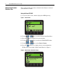
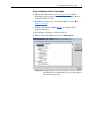
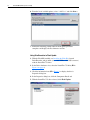
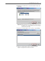
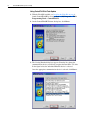
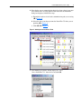
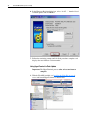
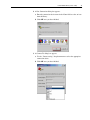
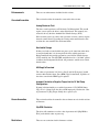
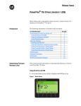
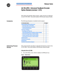
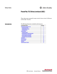
Release Notes
PowerFlex® 753 Drives (revision 1.010)
These release notes correspond to major revision 1, minor revision 10 of
firmware for PowerFlex® 753 AC drives.
Introduction
The following information is included in this document:
For information about:
Determining Firmware Revision Level
Using the Drive LCD HIM
Using DriveExplorer Lite/Full
Using DriveExecutive
Firmware Flashing
Installing the Flash Kit
Using DriveExplorer Lite/Full to Flash Update
Using DriveExecutive to Flash Update
Using ControlFLASH to Flash Update
Using HyperTerminal to Flash Update
Enhancements
Corrected Anomalies
Rockwell Automation Support
See page:
2
2
3
3
4
4
5
6
8
10
15
15
16
2
PowerFlex® 753 Drives (revision 1.010)
Determining Firmware
Revision Level
This section describes procedures to determine the firmware revision of
your PowerFlex 753 drive.
Using the Drive LCD HIM
1. Access the Status screen, which is displayed on HIM power up.
Figure 1 Status Screen
Host Drive
480V
2.1A
20F...D2P1
2. Use the
or
key to scroll to Port 00 for the Host Drive.
3. Press the
key to display its last-viewed folder.
4. Use the
or
key to scroll to the DIAGNOSTIC folder.
5. Use the
or
key to select Device Version.
6. Press the
(Enter) key to display device version information.
FW Revision is listed under –Main Control Board; see Figure 2.
Figure 2 Device Version Information Screen
PowerFlex 753 480V 2.1A
Product Series A
Product Revision 1.007
Product Serial Number SN
–Main Control Board
FW Revision
1.010
PowerFlex® 753 Drives (revision 1.010)
3
Using DriveExplorer Lite/Full
Important: You need DriveExplorer version 6.02 or later to interface
with the PowerFlex 753 drive. To obtain the latest version,
visit the Allen-Bradley Web Updates site located at
http://www.ab.com/support/abdrives/webupdate.
1. Launch DriveExplorer and go online with the PowerFlex 753 drive. To
connect to the drive, use a 1203-USB converter, a 1203-SSS converter, or
an EtherNet/IP network connection.
2. In the Devices hardware view, select the PowerFlex 753 drive.
Once selected, information regarding the PowerFlex 753 drive is shown
in the right panel including the current firmware revision number.
Using DriveExecutive
Important: You need DriveExecutive version 5.02 or later to interface
with the PowerFlex 753 drive. To obtain the latest version,
visit the Allen-Bradley Web Updates site located at
http://www.ab.com/support/abdrives/webupdate.
1. Launch DriveExecutive and go online with the PowerFlex 753 drive. To
connect to the drive, use a 1203-USB converter, a 1203-SSS converter, or
an EtherNet/IP network connection.
2. In the Drives hardware view, select the PowerFlex 753 drive (X in
Figure 3 on page 4).
3. Click the information icon (Y in Figure 3) to display the drive’s
Properties dialog box.
4. In the Properties dialog box, the “Revision:” field (Z in Figure 3) will
show the drive’s current firmware revision number.
4
PowerFlex® 753 Drives (revision 1.010)
Figure 3 PowerFlex 753 Drive Information Accessed Through DriveExecutive
Y
X
Z
Firmware Flashing
This section describes procedures to flash upgrade your drive firmware.
Flash kits for drives are provided on the Allen-Bradley Web Updates site
located at http://www.ab.com/support/abdrives/webupdate.
Flashing can be performed using a 1203-USB or 1203-SSS converter. For
information on connecting either converter to your drive, refer to the
1203-USB USB Converter User Manual, publication DRIVES-UM001 or
the 1203-SSS Smart Self-powered Serial Converter User Manual,
publication 20COMM-UM001.
Installing the Flash Kit
1. Install the flash kit utility from the Allen-Bradley Web Updates site for
the PowerFlex 753 drive, which includes the latest version of the
ControlFLASH utility and deploys firmware files for using
HyperTerminal on your computer.
2. You are now ready to use DriveExplorer, DriveExecutive,
ControlFLASH or HyperTerminal to update the drive. Refer to the
respective section and follow the instructions.
PowerFlex® 753 Drives (revision 1.010)
5
Using DriveExplorer Lite/Full to Flash Update
1. With the Flash Kit installed (see Installing the Flash Kit), launch
DriveExplorer and go online (via a 1203-USB or 1203-SSS converter)
with the PowerFlex 753 drive.
2. In the Drives hardware view, select the PowerFlex 753 drive (X in
Figure 3 on page 4).
3. Click the information icon (Y in Figure 3) to display the drive’s
Properties dialog box.
4. In the Properties dialog box, click the Details tab.
5. With the Main Control Board selected, click Flash Update.
Important: Flash updating the device firmware may cause the device to
load defaults. It is recommended that you save the setting to
your PC before proceeding.
6
PowerFlex® 753 Drives (revision 1.010)
6. From the list of available updates, select “v1.007.xxx” and click Next >.
7. Follow the remaining prompts until the flash update procedure
completes and displays the new firmware revision.
Using DriveExecutive to Flash Update
1. With the Flash Kit installed (see Installing the Flash Kit), launch
DriveExecutive and go online (via a 1203-USB or 1203-SSS converter)
with the PowerFlex 753 drive.
2. In the Drives hardware view, select the PowerFlex 753 drive (Y in
Figure 3 on page 4).
3. Click the information icon (Z in Figure 3) to display the drive’s
Properties dialog box.
4. In the Properties dialog box, click the Component Details tab.
5. With the PowerFlex 753 drive selected, click Flash Update.
PowerFlex® 753 Drives (revision 1.010)
7
6. From the list of available devices, select the PowerFlex 753 drive and
click Next >.
Important: Flash updating the device firmware may cause the device to
load defaults. It is recommended that you save the setting to
your PC before proceeding.
7. From the list of available updates, select “v1.007.xxx” and click Next >.
8. Follow the remaining prompts until the flash update procedure
completes and displays the new firmware revision.
8
PowerFlex® 753 Drives (revision 1.010)
Using ControlFLASH to Flash Update
1. With the Flash Kit installed (see Installing the Flash Kit on page 4),
launch ControlFLASH by selecting Start > (All) Programs > Flash
Programming Tools > ControlFLASH.
2. On the ControlFLASH Welcome dialog box, click Next >.
3. The Catalog Number dialog box appears. From the list, choose the
communication device you will use to update the PowerFlex 753 drive.
In the figure below, the embedded EtherNet device is selected.
Once the appropriate communication device is selected, click Next >.
PowerFlex® 753 Drives (revision 1.010)
9
4. Now that the correct communication device has been selected, you must
select which device is being updated. With the Select the PowerFlex…
dialog box displayed, follow these steps.
a. Expand the hardware view for the communication path you are using
(X in Figure 4).
b. Select the drive icon that represents the PowerFlex 753 drive you are
updating (Y in Figure 4).
c. Click OK (Z in Figure 4).
Figure 4 Selecting the Correct Drive to Flash
X
Y
Z
5. In the Multiple Assemblies Found display box, select
“Port x-PowerFlex 753” from the list and click OK.
10
PowerFlex® 753 Drives (revision 1.010)
6. In the Firmware Revision dialog box, select “v1.007…” from the list of
available updates and click Next >.
7. Follow the remaining prompts until the flash procedure completes and
displays the new firmware revision number.
Using HyperTerminal to Flash Update
Important: The HyperTerminal process takes at least one hour to
complete.
1. With the Flash Kit installed (see Installing the Flash Kit on page 4),
access and launch HyperTerminal as shown below.
PowerFlex® 753 Drives (revision 1.010)
11
2. A New Connection dialog box appears.
a. Enter the connection device name in the Name field or select an icon
from the library.
b. Click OK once you have finished.
3. A Connect To dialog box appears,
a. Use the “Connect using:” drop-down menu to select the appropriate
connection device.
b. Click OK once you have finished.
12
PowerFlex® 753 Drives (revision 1.010)
4. A Properties dialog box will appear for the selected connection device.
a. Use any of the drop-down menus to change the various port settings.
b. Click OK once you have finished.
5. After you click OK, you will get a blank screen.
Press Enter on your computer keyboard so the following test screen
appears.
6. From the Main Menu, select the flash upgrade (X in Figure 5 on
page 13) by pressing the number 3 key on your computer keyboard.
7. Additional text appears. From the Flash Upgrade menu, select the
PowerFlex 753 drive (Y in Figure 5) by pressing the number 0 key on
your computer keyboard.
8. Additional text appears. After reading the conditions, select Yes (Z in
Figure 5) to proceed by pressing the letter Y key on your computer
keyboard.
PowerFlex® 753 Drives (revision 1.010)
13
Figure 5 HyperTerminal Test Screen Dialogue
X
Y
Z
The terminal program will start displaying the letter “C”. This signals the
XMODEM protocol that the download may proceed. You then have one
minute to start the transfer.
Important: You have one minute to complete steps 9…14 or
HyperTerminal will return to step 5, where you must repeat
steps 5…8.
TIP: To cancel the flash update at any time, press CTRL-X.
9. Select Transfer > Send File to display the Send File screen.
10.Click Browse and navigate to
C: > Program Files > ControlFLASH > 0001 > 0086 > 0490
14
PowerFlex® 753 Drives (revision 1.010)
11.Search through the subfolder until the “PF753_LP_App_v1_007_xxx.dpi”
file appears in the Select File to Send list.
12.With the file name highlighted, click Open so it appears in the Filename
data field in the Send File dialog box.
13.In the Protocol box, select “Xmodem.”
14.Click Send.
A dialog box appears and reports the progress of the update. This
process takes at least one hour for HyperTerminal to complete.
When it is complete, the message “Flash Complete” appears.
15.Press any key to continue.
16.Press the Enter key to return to the main menu.
PowerFlex® 753 Drives (revision 1.010)
Enhancements
There are no enhancements included in this revision.
Corrected Anomalies
This section describes the anomalies corrected in this revision.
15
Analog Checksum Fault
The drive would experience an F108 Anlg Cal Chksum fault. This would
require you to replace the drive’s main control board. This anomaly was
related to the way the drive handled Non-Volatile Storage (NVS).
If this anomaly occurs on a drive with a previous revision, you must replace
the main control board. Upgrading the existing main control board to this
revision does not remediate the checksum failure.
Non Volatile Storage
If thirty two faults occurred within one power cycle (time from when drive
is energized until time it is de-energized) the drive would experience a
Background Stall fault and the parameters stored in Non Volatile Storage
(NVS) would be lost. The STS LED would flash red in a “24-blink” pattern
to indicate the Background Stall fault. All parameters would revert to their
default values.
HIM CopyCat Download
The values of parameters 301 [Access Level] and 302 [Language] would
return to their default values after a HIM CopyCat download, regardless of
the values stored in the HIM CopyCat upload.
Improper Calculation of Negative Torque Limit for Oil Well Pump
Configurations
If pump jack functionality was enabled (parameter 1179 [OilWell Pump
Cfg] set to 1 = Pump Jack), the drive would improperly calculate the value
of parameter 671 [Neg Torque Limit] after a power cycle.
Known Anomalies
This section describes the anomalies that are known to exist in this revision
of firmware.
Slip RPM Calculation
The drive will sometimes reset the value of parameter 621 [Slip RPM at
FLA] to the default value on power-up.
Restrictions
There are no restrictions for this firmware revision.
Rockwell Automation
Support
To assist you, Rockwell Automation provides technical information on the
web. At http://www.rockwellautomation.com/support, you can find technical
manuals, a knowledge base of Frequently Asked Questions (FAQs),
technical and application notes, sample code and links to software service
packs, and a MySupport feature you can customize to best use these tools.
Rockwell Automation also provides complimentary phone support for
drives, option modules, and peripherals. If you experience a problem with
the option module, please review its documentation. For further help,
contact a Customer Support representative:
United States
Outside United States
(1) 262.512.8176
Monday – Friday, 7am – 6pm CST
Please contact your local Rockwell Automation representative for any
technical support issues.
For an additional level of technical phone support for installation,
configuration, and troubleshooting, we offer TechConnect Support
programs. For more information, contact your local distributor or Rockwell
Automation representative, or visit http://www.rockwellautomation.com/
support.
U.S. Allen-Bradley Drives Technical Support - Tel: (1) 262.512.8176, Fax: (1) 262.512.2222, Email: [email protected], Online: www.ab.com/support/abdrives
www.rockwellautomation.com
Corporate Headquarters
Rockwell Automation, 777 East Wisconsin Avenue, Suite 1400, Milwaukee, WI, 53202-5302 USA, Tel: (1) 414.212.5200, Fax: (1) 414.212.5201
Headquarters for Allen-Bradley Products, Rockwell Software Products and Global Manufacturing Solutions
Americas: Rockwell Automation, 1201 South Second Street, Milwaukee, WI 53204-2496 USA, Tel: (1) 414.382.2000, Fax: (1) 414.382.4444
Europe/Middle East/Africa: Rockwell Automation SA/NV, Vorstlaan/Boulevard du Souverain 36, 1170 Brussels, Belgium, Tel: (32) 2 663 0600, Fax: (32) 2 663 0640
Asia Pacific: Rockwell Automation, 27/F Citicorp Centre, 18 Whitfield Road, Causeway Bay, Hong Kong, Tel: (852) 2887 4788, Fax: (852) 2508 1846
Headquarters for Dodge and Reliance Electric Products
Americas: Rockwell Automation, 6040 Ponders Court, Greenville, SC 29615-4617 USA, Tel: (1) 864.297.4800, Fax: (1) 864.281.2433
Europe/Middle East/Africa: Rockwell Automation, Brühlstraße 22, D-74834 Elztal-Dallau, Germany, Tel: (49) 6261 9410, Fax: (49) 6261 17741
Asia Pacific: Rockwell Automation, 55 Newton Road, #11-01/02 Revenue House, Singapore 307987, Tel: (65) 6356-9077, Fax: (65) 6356-9011
Publication 750-RN011C-EN-P – June, 2011
Supersedes 750-RN011B-EN-E – February, 2011
Copyright © 2011 Rockwell Automation, Inc. All rights reserved. Printed in USA.