1
TECHNICAL MANUAL - FX/10
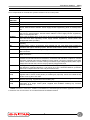
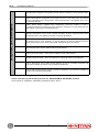
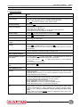
4. CHARACTERISTICS
4.1 Technical features
Model:
FX/10
Protection class:
IP3X
Power supply:
230V
(+10% -15%), 50/60 Hz, double insulated transformer is mounted on to
housing base, switching power unit controlled by microprocessor.
24V
from back up batteries, 2x12V 6,5Ah in series.
Operating voltage:
20V to 30V
Power consumption:
from mains 350 mA @ 230V
Main board: 120 mA @ DC24V
1 FX10 MINILOOP Loop module: 10 mA @ DC24V without detectors
60 mA @ DC24V with 254 detectors connected
Output voltage:
27,90V
at LOAD terminal board ( 21,43V to 27,71V
Battery recharging voltage:
27,50V
at Faston terminals.
Residual ripple:
1,376 V
at LOAD output.
Battery recharging power
supply:
1,7A
BELL OUTPUT terminals
voltage:
).
27,10V
in ALARM mode (19,71V to 26,75V
).
Outputs are supervised with guard voltage featuring polarity opposed to terminal
board printing.
Residual ripple:
1,240 V
Current available at
BELL OUTPUT terminals:
0,5A max. @24V with supervised relay output.
Current available at power
unit output:
1 A max. @ 24 V
to power: main board + FX10 MINILOOP loop module at
max configuration and supervised outputs max consumption;
500 mA max. @ 24 V
to LOAD terminal board to power additional
components;
0,7 A to recharge back up battery
Current supplied by power
unit:
Max 1 A @ 24 V
Current supplied by
FX10 MINILOOP board:
500mA max.
Presets:
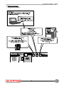
Cable with connector to connect and manage several power units, FXC72H cable
required (optional).
Cable with NTC to fix directly on one of back up batteries housing to control current
supply related to internal temperature.
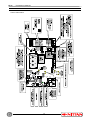
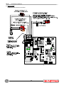
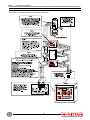
Connectors on main board
for:
1 FX10 MINILOOP board,
1 FX10-485 serial interface board (optional), 1 ETR-LAN board,
for power cable from mains transformer secondary winding,
for 40-zone FX/EXP10 board (optional),
Minidin FIRMWARE connector, to download firmware,
Minidin MODEM-PC connector to connect compatible devices,
Minidin PRINTER connector to connect PRT serial printer.
Terminals on main board
for:
2 relay outputs supervised and programmable to connect FIRE BELLS,
RELAY output 1 for FAULT event with C-NO-NC contacts, RELAY output 2 FIRE
ALARM programmable for events signalling with C-NO-NC contacts, RELAY
outputs 1 and 2 must be connected to circuits operating with SELV current
ONLY.
RS485 output on FX10-485 optional board for peripherals control: power units,
repeaters and mimic repeaters.
at BELL OUTPUT terminals in ALARM mode.
.
9