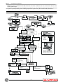
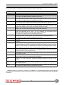
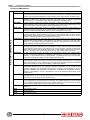
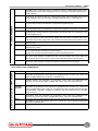
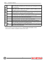
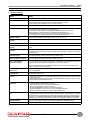
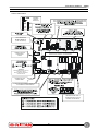
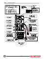
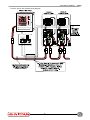
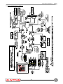
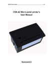
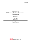
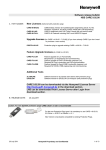
1
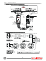
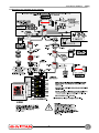
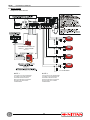
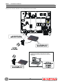
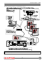
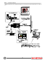
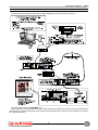
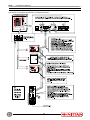
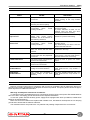
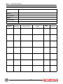
CONFORMITY
EN 54 - 2 1997
UNI EN 54 - 2 - 1999
CONTROL PANELS
EN 54 - 4 - 1997
UNI EN 54 - 4 - 1999
POWER SUPPLY UNITS
Analogue-addressable fire panel
FX/50
TECHNICAL MANUAL
FX/50 - TECHNICAL MANUAL
FOREWORD
FOR THE INSTALLER:
Please follow carefully the specifications relative to electric and security systems realization further to the manufacturer’s prescriptions indicated in the manual provided.
Provide the user the necessary indication for use and system’s limitations, specifying that there exist precise
specifications and different safety performances levels that should be proportioned to the user needs. Have the user
view the directions indicated in this document.
FOR THE USER:
Periodically check carefully the system functionality making sure all enabling and disabling operations were made correctly.
Have skilled personnel make the periodic system’s maintenance. Contact the installer to verify correct system operation in case its conditions have changed (e.g.: variations in the areas to protect due to extension, change of the access modes, etc…)
......................................................
This device has been projected, assembled and tested with the maximum care, adopting control procedures in
accordance with the laws in force. The full correspondence to the functional characteristics is given exclusively when
it is used for the purpose it was projected for, which is as follows:
Analogue-addressable fire panel
Any use other than the one mentioned above has not been forecasted and therefore it is not possible to guarantee
its correct operativeness.
The manufacturing process is carefully controlled in order to prevent defaults and bad functioning. Nevertheless, an
extremely low percentage of the components used is subjected to faults just as any other electronic or mechanic product. As this item is meant to protect both property and people, we invite the user to proportion the level of protection
that the system offers to the actual risk (also taking into account the possibility that the system was operated in a degraded manner because of faults and the like), as well reminding that there are precise laws for the design and assemblage of the systems destinated to these kind of applications.
The system’s operator is hereby advised to see regularly to the periodic maintenance of the system, at least
in accordance with the provisions of current legislation, as well as to carry out checks on the correct running
of said system on as regular a basis as the risk involved requires, with particular reference to the control unit,
sensors, sounders, dialler(s) and any other device connected. The user must let the installer know how well
the system seems to be operating, based on the results of periodic checks, without delay.
Design, installation and servicing of systems which include this product, should be made by skilled staff with the necessary knowledge to operate in safe conditions in order to prevent accidents. These systems’ installation must be
made in accordance with the laws in force. Some equipment’s inner parts are connected to electric main and therefore
electrocution may occur if servicing was made before switching off the main and emergency power. Some products
incorporate rechargeable or non rechargeable batteries as emergency power supply. Their wrong connection may
damage the product, properties and the operator’s safety (burst and fire).
YOUR DEALER:
2
TECHNICAL MANUAL - FX/50
1. GENERALS
FX/50 analogue addressable fire detection control panel is a sophisticated, microprocessor-based fire detection control unit. It can manage five loops operating with different protocols: analogue-addressable AS protocol and Evolution protocol. The operational principle is based on a communication protocol specific for the
type of loop installed allowing prompt identification of systems alarms and faults.
FX/50 control unit has been designed for fire-detection systems management and is particularly suitable for
large-size installations, such as hotels, company buildings, shopping centres and office blocks, all areas requiring high technological performance, quick installation, and easy management.
The combined installation of a fire panel and a loop for EVOLUTION detectors allows using a new type of
FSK signal transmission: this ensures a high immunity to noise and features a low EMC impact so that it can
be installed in sensitive environments such as operating theatres, hospitals, and analysis labs.
FX/50 fire detection control unit can control up to 120 zones through the generation of various ’alarm’ or
’fault’ signals following system events, logic events or patterns.
Main features:
• controls up to 5 loops;
• controls up to 254 analogue addressable devices;
• control of 120 zones;
• controls 2 different loop modules:
FX/EXP01 for installation of analogue-addressable devices operating with AS protocol,
FXEXPEV for installation of devices operating with Evolution protocol.
• setup via keypad (on the front panel) or via PC with WINFIRE v.4.x software either in direct or
remote connection;
• setup via keypad (on the front panel) or via PC with WINFIRE software either in direct or remote
connection;
• pre-set for:
- remote connection of mimic repeaters, control panels, and printers;
- connection to PCs with WINFIRE v.4.x software for graphic maps and remote assistance;
- network connection of max 16 FX fire panels;
- FX-LAN module installation (optional) for Ethernet network connection and management with
WINFIRE v.4.x or Global Management application;
- FX-485 module installation (optional) for management of panels networks or connection to special devices such as F.O. converters;
• pre-set to be managed by Global Management supervision software
• management of input and output devices through logic events, system events, and patterns;
• definition of filters for special management of events memory and printing process;
• logic equation definition for advanced management;
• weekly programmer for detectors sensitivity and delayed mode setup;
• standard / scheduled thresholds setup;
• date/time setup and daylight saving time switch;
• multi-language menu: Italian, English, Spanish, and German;
• operating control of sensors, delay mode, and sensitivity with thresholds that can be
grammed by alarm, pre-alarm, and maintenance;
pro-
• the most recent 4000 events stored in the memory;
• 4 access levels with 10 user passwords for passage from Level 1 to Level 2; 10 maintenance passwords for passage from Level 2 to Level 3; level 4 (manifacturer) is for firmware update procedure
and is accessible by manifacturer only:
• management of the supervised power supply unit with front door control;
• large and sturdy housing with mechanical key for front panel opening, dust protection seal;
• built-in boards holder to make installation easy;
• CE Conformity;
• UNI-EN54 Part 2 and Part 4 compliance.
3
FX/50 - TECHNICAL MANUAL
NOTE: to ensure compliance with IMQ Sistemi di Sicurezza certification, do not connect more than 512 devices to panel loops.
This manual includes wiring and installation procedures only. See FX/50Programming Manual for a detailed
description of panel operating mode, settings required for passwords, panel ID and other parameters.
2. BLOCK DIAGRAM
LINE ISOLATOR
SCI-4
ADDRESSABLE MODULE
WITH RELAY CONTROL IN BOX 1
OCM-AS2B
LINE ISOLATOR
SCI-4
5 x 1-LOOP
BOARDS MAX
1-LOOP BOARD
WITH
254 ADDRESSES
(IN-OUT)
AS PROTOCOL
1-LOOP BOARD
WITH
254 ADDRESSES
(IN-OUT)
EVOLUTION PROTOCOL
LCD DISPLAY
SERIAL outputs
to connect peripherals
such as:
PRT
SERIAL
PRINTER
CONTROL PANEL
MANUAL
CONTROL
FIRE
ALARM
MANNED SYSTEM
DELAYED ACTIVATION
DUE TO:
AUTOMATIC
CONTROL
UNMANNED SYSTEM
IMMEDIATE
ACTIVATION
PC FOR PANEL SETUP,
GRAPHIC MAPS DISPLAY
AND REMOTE ASSISTANCE
ALARM
PRESET TIME
ELAPSED
RESET
GENERAL ALARM OUTPUT
TO CONTROL:
- ELECTROMAGNETS
- DIALLERS
- ADDITIONAL DEVICES
AUTOMATIC
TELEPHONE
DIALLER
SOS
FAULT OUTPUT
TO CONTROL:
- DIALLER
- OPTICAL/ACOUST. DEVICES
2 SUPERVISED ALARM OUTPUTS
TO CONTROL AND POWER:
- BELLS
- LUMINOUS BOARDS
- SELF POWERED SIRENS
4
TECHNICAL MANUAL - FX/50
3. FX/50 SYSTEM COMPONENTS
List of components for fire detection systems based on FX/50 control panel:
Code
Description
FX/485
RS485 interface. (Non certified IMQ-SISTEMI DI SICUREZZA).
FX/EXP10
40-led zone board.
FX/EXP212
Control board for automatic extinguishing systems.
(Non compliant with IMQ-SISTEMI DI SICUREZZA certification).
FX/RP10
Remote repeater for visualization, featuring LCD display for indications and LED for general
alarms, internal buzzer ON/OFF. Power supply DC24V supplied by panel or remote power box.
(Non compliant with IMQ-SISTEMI DI SICUREZZA certification).
FX/RP20
Remote repeater for visualization and control, featuring keypad, LCD display for indications and
LED for general alarms, internal buzzer ON/OFF. Power supply DC24V supplied by panel or
remote power box. (Non compliant with IMQ-SISTEMI DI SICUREZZA certification).
FX/SIN01
Mimic panel including driver circuit and a 40-zone FX/SIN10 board with terminal outputs for zone
fault and alarm signalling. (Non compliant with IMQ-SISTEMI DI SICUREZZA certification). Power
supply DC24V supplied by remote power unit equipped with back up battery.
FX/SIN10
40-zone expansion board for FX/SIN01 panel with terminal outputs for zone fault and alarm
signalling. (Non compliant with IMQ-SISTEMI DI SICUREZZA certification).
FX/CNV
RS485 to RS232 serial line converter to connect PC to FX-series fire alarm control panels,
supplied with DB25/DB9 RS-232 cable to use with FX/GRMAP and FX/CFGMAP software
applications, galvanic insulation of field bus. Power supply unit included.
(Non compliant with IMQ-SISTEMI DI SICUREZZA certification).
PRT
Impact printer, 4,000 x 23-character lines printable per roll, uses plain paper suitable for
calculators with paper rewinding system, RS-232 serial interface, power supply AC230V.
(Non compliant with IMQ-SISTEMI DI SICUREZZA certification).
CP8/SER2
Connecting cable for direct programming software and PRT printer connection. MINIDIN/DB9
connectors.
CP8/SER3
Modem connecting cable for remote programming and assistance connection. MINIDIN/DB25
connectors.
FX/AL01
Intelligent supervised power supply unit, outputs and relays for general alarm and fault, terminals
for RS-485 serial line connection, connectors with electronic outputs to connect CP8/ REL
optional board and 5 UNIREL/24 relay boards, connector to display single fault events, can be
housed in C11/S24 housing not included. EN54-4 conformity. Input voltage AC230V, 50/60Hz,
output voltage DC27.6V full load, current carrying capacity 4A @ DC24Vmax.
C11/S24
Housing for installing FX/AL01, AL/4SW24 and AL/2.4 power supply units, featuring front LED
board for general indications, it can house up to two 12V/24Ah batteries, protection class IP3X.
Complies with CEI 79-2 2nd performance level.
FX/STDv.4.x
Software application WINFIRE v.4.x for direct configuration, included on to WARBL039 CD-Rom
supplied with FX series control panels (no enabling key required). It does not enable saving panel
event log file to PC HDD.
FX/CFGv.4.x
Software WINFIRE v.4.x for direct and remote configuration, remote assistance, event log and
analogue detectors event log, supplied with CFG enabling key.
FX/CFGMAP
v.4.x
Graphic software application WINFIRE v.4.x for direct configuration, remote assistance and
supervision of a single control panel, supplied with CFGMAP enabling key. FX/CNV converter
required.
FX/GRMAP
v.4.x
Graphic software application v.4.0 for direct configuration, remote assistance and supervision of a
control panel network, supplied with GRMAP enabling key. PC management over network. FX/
CNV converter required.
FXLAN
10 Base T Ethernet LAN interface for LAN network connection, supplied with plastic housing.
(Non compliant with IMQ-SISTEMI DI SICUREZZA certification).
NOTE: FX/STDv4.x, FX/CFGv4.x, FX/GRv4.x, FX/GRMAPv4.x, and Global Management software applications, and Remote Assistance and Remote Control functions do not comply with IMQ-SISTEMI DI SICUREZZA
certification.
5
FX/50 - TECHNICAL MANUAL
AS LOOP COMPONENTS
AS LOOP COMPONENTS:
FX/EXP01
Loop expansion board, supports up to 254 AS devices.
SCI-3
Line isolator unit, which can be installed on the detector’s base, for disabling part of the loop in
case a short-circuit occurs whilst normal operation is continued on remaining equipment (an
isolator every 32 detectors/addresses recommended), power supply DC24V supplied by loop.
SCI-4
Line isolator unit for disabling part of the loop in case a short-circuit occurs whilst normal
operation is kept on the remaining equipment (an isolator every 32 detectors/addresses
recommended), housed in BOX1 case, power supply DC24V supplied by loop.
NAM-AS2B
1-input analogue addressable module, AS series, it allows connecting any conventional
detector featuring a NO contact output. The address on the unit is set via 8 dip-switches, it can
be housed in BOX1 or BOX2 (optional), power supply DC24V from loop.
NAM4-AS2B
4-input analogue addressable module, AS series, it allows connecting 4 fire detectors or
devices featuring a NO relay output to a detection loop. The address on the unit is set via 8 dipswitches, it can be housed in BOX3 (optional), power supply DC24V from loop.
OCM-AS2B
1-output analogue addressable module, AS series, to be connected to detection loop. It allows
controlling fire alarm devices featuring an activation input. Equipped with 2 outputs: 1x10mA
open-collector output at DC24V and 1 C/NC/NO relay output (2A at DC30V). It can be housed
in BOX1 or BOX2 (optional), power supply DC24V from loop.
OCM4-AS2B
Analogue addressable unit, AS series, with 4 relay outputs used to control optical acoustic
alarm devices, optical panels or other devices. The address on the unit is set with 8 dipswitches, 4 relay outputs with 0.6A capacity @ AC125V - 2A @ DC30V, can be housed in
BOX3 (optional), power supply DC24V from loop.
IOM4-AS2B
Analogue addressable module, AS series, allows to connect 4 conventional detectors featuring
NO relay outputs to a detection loop, and enables to control optical acoustic alarm devices,
optical panels or other devices; unit address is set via 8 dip-switches, terminals for NO inputs,
alerts, relay outputs and for serial loop connection, 4 relay outputs (0.6A capacity at AC125V
and 2A at DC30V), can be housed in BOX3 (optional), power supply DC24V from loop.
MCM-AS3B
Control and monitoring module, AS series, can be inserted onto detection loop, used to monitor
20 ST-P conventional detectors or 5 NFD/68P flame detectors, unit address is set via 8 dipswitches, 1 x open-collector output, 10mA at DC24V, 1 x C/NC/NO relay output, 2A at DC30V,
can be housed in BOX1 (optional), power supply DC24V from loop.
SCM-AS2B
Module to control sounders, AS series, can be inserted onto detection loop, inputs for local
silencing button, SYNC input, input for break in power supplied by external box, 1 supervised
output for sounders (1A max. current draw), unit address is set via 8 dip-switches, dimensions
W80 x H50 x D20mm, can be housed in BOX1, power supply DC24V.
NAM-AS-G
Analogue-addressable interface, AS series, to connect a 4-20mA gas detector to an analogue
addressable detection loop. The detector’s operating parameters can be monitored and
operating thresholds set. Connectable detectors are: TS910EC-S and TS220EC-S for CO
detection, TS293KG and TS292KG for LPG detection, TS293KM and TS292KM for methane
detection. Unit address is set via 8 dip-switches. Unit can be housed in BOX3 IP56, power
supply DC24V.
MTB
Analogue-addressable unit for local alarm, AS series, can be connected to pull-cord switches,
“pull-cord alarms” or for room calls. Unit address is set via 8 dip-switches, dimensions W59H40-D15mm, power supply DC24V supplied by loop.
VCT-03NTAS
Sounder module, AS series, for FX-series control panels analogue loop. Can be installed alone
on an analogue loop as sounder with red cover mod. VCT-03CPR (optional), or can be hooked
to an analogue addressable detectors base (STB-4 optional), 4-tone sound power, 91dB.
Address set with 8 dip-switches, power supply DC8-35V from loop.
STB-4
Standard base for ST-P-LV, ST-P-AS, ST-H-AS, NHD-G2, 2SC-LS, and VCT-03NTAS
detectors.
BOX1
IP55 module housing.
BOX2
Module housing.
BOX3
IP56 module housing.
6
TECHNICAL MANUAL - FX/50
ST-P-AS
Analogue-addressable smoke detector, AS series, Tyndall-effect operation, thresholds
adjustable during control panel setup, IP protection class 42, supplied without base, STB-4compatible base. DC24V power supplied by loop. CE conformity. It complies with EN54 part 7 LPCB approved.
ST-H-AS
Analogue-addressable temperature detector, AS series, thresholds adjustable during control
panel setup, IP protection class 42, supplied without base, STB4-compatible base. DC24V
power supplied by loop. CE conformity. It complies with EN54 part 5 - LPCB approved.
AS LOOP COMPONENTS
ST-NCP-AS2B Analogue-addressable glassbreak fire alarm call point, AS series, 2 status LED indicators, test
key, internal dip-switch to set addresses, power DC24V supplied by loop.
ST-NCP-EN
Analogue-addressable pressure fire alarm call point, AS series, 2 status LED indicators, unlock
key, internal dip-switch to set addresses, power DC24V supplied by loop. EN54-11 conformity.
ST-NCP-IP
Analogue addressable glassbreak fire alarm call point, AS series, IP67, film for protection
against injuries, test key and status LED indicators, internal dip-switch to set addresses, power
DC24V supplied by loop.
RFP-AS2B
Optical-acoustic repeater module for AS analogue addressable loops of fire alarm systems. It
does not require any other control device. Signals and LED indicator operating mode can be
customized. Device with 2 side LEDs, built-in buzzer and reduced-dimensions plastic housing.
4I-AS
Input module with 4 balanced inputs to connect devices featuring NO output contacts over the
detection loop.
4O-AS
Output module with 4 C/NC/NO relay outputs to control fire equipment featuring a free-frompotential input contact.
4I4O-AS
I/O module with 4 balanced inputs and 4 C/NC/NO relay outputs.
Inputs support devices featuring a NO output contact.
Outputs can control fire equipment featuring a free-from-potential contact.
2D-AS
Access control module for full control of two access points (e.g. fire doors, dormer windows,
etc.). Each relay manages two balanced inputs: one input controls open access status, the
other controls closed access status, in order to allow detecting half-open doors/windows.
4D-AS
Access control module to control four access points (e.g. fire doors, dormer windows, etc.).
Each relay output manages one balanced input that controls closed access status.
EVOLUTION LOOP COMPONENTS
EVOLUTION LOOP COMPONENTS:
FXEXPEV
Loop expansion board, supports up to 254 Evolution devices.
EV-P
Analogue-addressable smoke detector EVOLUTION-series, fotoelectric operation, IDs
assignable via programmer, alarm signal from OMNIVIEW 360° luminous ring, remote LED
output. Supplied without base, STB-4-EV compatible base.
EV-DP
Analogue-addressable smoke detector EVOLUTION-series, fotoelectric operation with double
analysis chamber, IDs assignable via programmer, alarm signal from OMNIVIEW 360°
luminous ring, remote LED output. Supplied without base, STB-4-EV compatible base.
EV-H
(EVH-AIR)
(EVH-CS)
Analogue-addressable heat detector EVOLUTION-series, thresholds temperature 62°C, IDs
assignable via programmer, alarm signal from OMNIVIEW 360° luminous ring, remote LED
output. Supplied without base, STB-4-EV compatible base. (Non compliant with IMQ-SISTEMI
DI SICUREZZA certification). Available in 2 versions: rate-of-rise (EVH-AIR, 62°C) and static
(EVH-CS, 85°C).
EV-PH
Combined analogue-addressable heat and smoke detector EVOLUTION-series, thresholds
temperature 62°C, IDs assignable via programmer, alarm signal from OMNIVIEW 360°
luminous ring, remote LED output. Supplied without base, STB-4-EV compatible base.
EV-UV
Ultra-violet analogue addressable fire detector EVOLUTION-series, detect fire ultra-violet light,
the address is set via dip-switches, alarm LED, remote LED output. Supplied without base,
STB-4-EV compatible base.
STB-4-EV
Base for EVOLUTION detectors. Setscrew to lock base to detector.
7
EVOLUTION LOOP COMPONENTS
FX/50 - TECHNICAL MANUAL
EV-AIO21
Analogue-addressable module EVOLUTION series with functions settable by means of a dipswitch, allows different configuration of its 2 inputs and of its 1 relay output, type: input module
function, emergency doors check function, exit command function. The address on the unit is
set via 8 dip-switches.
EV-AIN1
Analogue-addressable module EVOLUTION series with functions settable by means of a dipswitch, allows setting 2 different input configuration: connection interface of max. 5
conventional detectors or interface for max.10 sensors connected to an intrinsically safe unit.
The address on the unit is set via 8 dip-switches.
EV-AIN2
Analogue-addressable module, EVOLUTION series, with functions set via dip-switch, allows
different configuration of its 2 inputs: sprinkler monitoring function, external systems status
monitoring function. The address on the unit is set via 8 dip-switches.
EV-ABS
Sounder module for EVOLUTION analogue loop. Can be installed alone on an analogue loop
as sounder with red cover (optional), or can be hooked to a base for analogue detectors
EVOLUTION-series. 2-tone sound power, 92dB. Address set with 8 dip-switches.
EV-AV
Addressable sounder beacon for analogue-addressable EVOLUTION loop, plastic container,
Xenon strobe, built-in buzzer. Address set with 8 dip-switches.
EV-SM
Sounder control module. Can be installed on detection loop EVOLUTION-series, input for
external power box failure; 1 alarm output. Address set with 8 dip-switches.
EV-MCP
Analogue-addressable glassbreak fire alarm call point for EVOLUTION loop. Film for
protection against injuries, 1 status LED indicators, internal dip-switch to set addresses.
SCI-5
Line isolator unit, which can be installed on the detector base, for disabling part of the loop in
case a short-circuit occurs whilst normal operation is kept on remaining equipment (we
recommend installing an isolator every 32 detectors/addresses).
SCI-6
Line isolator unit, supplied with box, that allows disabling part of the loop in case a short-circuit
occurs whilst normal operation is kept on remaining equipment (we recommend installing an
isolator every 32 detectors/addresses).
Please note that only the following devices are IMQ-SISTEMI DI SICUREZZA certified:
FX/50, FX/AL01, FX/EXP01, EF/EXPEV, FX/EXP10, SCI-3, SCI-4.
8
TECHNICAL MANUAL - FX/50
4. FX/50 SPECIFICATIONS
4.1 Electric features
Model:
FX/50
Protection class:
IP3X
Power supply:
AC230V (+10% -15%), 50/60 Hz, double insulated transformer is mounted on to
housing base, switching power unit controlled by microprocessor.
DC24V from back up batteries, 2x12V 6,5Ah in series.
Operating voltage:
DC20V to DC30V
Power consumption:
from mains 900 mA @ AC230V
main board and front keypad: 141 mA @ DC24V
1 FX/EXP01 Loop module: 31mA @ DC24V without detectors connected
82mA @ DC24V with 254 detectors connected (smoke detectors)
1 FX/EXPEV Loop module: 75mA @ DC24V without detectors connected
150mA @ DC24V with 254 detectors connected (smoke detectors)
Output voltage:
DC27,90V at LOAD terminal board ( DC21,43V to DC27,71V).
Battery recharging
voltage:
DC27,50V at Faston terminals.
Residual ripple:
AC1,376V at LOAD output.
Battery recharging power
supply:
1,5A
BELL OUTPUT terminals
voltage:
DC27,10V in ALARM mode (DC19,71V to DC26,75V).
Outputs are supervised with guard voltage featuring polarity opposed to terminal
board printing.
Residual ripple:
AC1,240V at BELL OUTPUT terminals in ALARM mode.
Current available at
BELL OUTPUT terminals:
1A max. @24V each supervised relay outputs (2OUTs).
Current available at
power unit output:
4A max. @ DC24V to power: main board + 2 FX/EXP01 loop modules at their max
expansion and with supervised outputs at their max consumption;
500 mA max. @ DC24V at LOAD terminal board to power additional components;
1,5A to recharge back up batteries
Current supplied by
power unit:
max 4A @ DC24V.
Current supplied by
LOOP board:
FX/EXP01: 500mA max.
FX/EXPEV: 350mA max
Presets:
- Cable with connector to connect and manage several power units, FXC72H cable
required (optional).
- Cable with NTC to fix directly on one of back up batteries housing to control current
supply related to internal temperature.
Connectors on main
board for:
- 5 LOOP modules (FX/EXP01 and FX/EXPEV or other compatible modules),
- 1 FX/485 serial interface board (optional),
- power cable from switching power unit (supplied),
- front board for display, setup and control,
- Minidin FIRMWARE connector, to download firmware,
- Minidin MODEM-PC connector to connect compatible devices,
- Minidin PRINTER connector to connect PRT serial printer.
Terminals on main board
for:
- 4 supervised relay outputs to connect FIRE BELLS,
- output RELAY1 for FAULT events with C-NO-NC contacts, output RELAY 2 for FIRE
ALARM events programmable for events with C-NO-NC contacts. Outputs RELAY 1
and RELAY 2 must be connected to circuits operating with SELV current ONLY.
- RS485 output for peripherals control: power units, repeaters and mimic repeaters.
Relays features:
RELAY 1 and RELAY 2 alarm relays with 8A @ AC250V switching contacts.
LED display:
LCD 4 rows/20 characters.
9
FX/50 - TECHNICAL MANUAL
Protection fuses:
F1 T1 A for +A -A BELL output,
F2 T1 A for +B -B BELL output,
F3 T1 A for +C -C BELL output,
F4 T1 A for +D -D BELL output,
Fuse on mains input terminal of T1A transformer.
On power unit board:
F2 T5 A for terminal board LOAD output protection,
F3 T2 A for terminal board CPU output protection,
F4 T2A for batteries protection against reverse polarity.
Indicators on power unit
board:
power supply LED, F6, F7, F8 fuses fault.
Indicators on front panel:
LED indicators for signalling and operating status, LCD display for visualization and
programming.
Keys:
setup keypad and keys.
Zone:
40, expandable to 120.
Devices supported:
max 512 devices assignable to a zone.
Operating temperature:
- 5 ÷ + 40°C – 93% UR
Weight:
9,3Kg with transformer.
Batteries (recomm.):
2 Extracell batteries, type ELB 26-12, 12V/26Ah, housing flammable rate UL94-HB or
above.
Dimensions:
W500 x H570 x D190 mm,
Parts supplied:
connecting cable for back up batteries wiring (in series), mechanical key to open
panel housing, technical manual, user manual, CD-Rom containing WINFIRE/
STDv4.0, power transformer (supplied in a separate box).
FX/50 control panel complies with EN54 - 2 1997 UNI EN54 - 2 1999 standards on control panels, and with
EN54 - 4 1997 UNI EN54 - 4 1999 on power supply devices.
Panel components have been selected according to the purpose they are to be employed for, therefore they
are suitable for operating as per general and technical features of manufacturer’s documentation when panel
environment conditions comply with 3K5 (IEC721-3-3).
10
TECHNICAL MANUAL - FX/50
4.2 Mechanical features
Housing overview.
5. INSTALLATION
IMPORTANT:
Verify that the electrical system is equipped with a proper ground connection.
Panel includes a power supply unit with double insulated transformer.
It is strongly recommended to use a suitable auxiliary protection device to be connected outside
the metal housing, as, for example, FAR filter for mains protection.
Use one auxiliary protection device for each auxiliary power supply unit connected to the
system.
Before installation, check CEI 64-8 standard concerning low-tension systems installation.
Operate professionally.
Steps:
A. Verify the existence of a ground connection.
B. Verify the ground connection is working properly.
C. Verify mains voltage quality, in order to avoid overvoltage problems that might occur in case the panel is
occasionally powered by a generator set.
D. Set the panel so as devices for disturbances suppression can be connected externally (for example
FAR filter).
E. In case of mains voltage instability, set the panel so as a saturated iron stabilizer can be connected.
F. Verify the existence of a magnetothermic switch, or set the panel for the connection of a suitable one,
which has to be bipolar and easilly accessible. Considerations about both people safety (equipment after
the switch operates at low-voltage) and surveillance systems continuous operation, lead to the use of a
magnetothermic switch only, so to grant mains power stabilty, though directives would indicate the use
of a diferential switch to avoid people electrocution.
11
FX/50 - TECHNICAL MANUAL
To ensure FAR protection devices proper working, they MUST BE INSTALLED outside
the metal cases of panels and auxiliary power supply units.
G. In order to choose the best position for panel installation, consider panel accessories wiring.
H. Wall-mount the panel (use screws and dowels size 8, or according to wall’s type and material) in a position that allows an easy access of mains cables and power cables for system devices.
THE WALL SHALL SUPPORT THE WEIGHT OF THE PANEL AND ITS COMPONENTS.
I. Install power supply transformer on to panel base, as per instruction below.
J. Devices wiring has to be performed by passing the cables through the holes on panel’s base; in case of
preprinted conduits located on panel upper and lower parts, use conduits made of material featuring
UL94-HB flammable rate (or above).
K. Pay great attention to the devices to install: FX/EXP01 module requires AS devices while FXEXPEV module requires Evolution devices.
L. Connect loop-through devices using suitable cables:
mod. CS/AI3 to cover distances up to 2Km, made of 2 x 0,8 sq.mm. rigid conduits, twisted and flameresistant shielded.
M. Connect non-powered cables as indicated; wiring has to be performed properly and neatly, and mains
cable must be introduced in a separate hole, not the same as all other cables will be passed through.
N. Wire terminal connections using stripped cable of suitable length, do not solder stranded cable.
O. Wire mains cable to transformer terminal board, then fix it permanently to housing base using a cable
gland passed through one of the several holes.
P. Fix cables orderly and properly; cables must be kept separate from very low voltage parts.
Q. Do not install panel or its components to extremely hot or humid places. Place them in dust-free locations
so to avoid internal air-ducts obstruction.
R. Install inside the panel two 12V/26Ah batteries; connect them to one other using the supplied cable (in
series). Batteries housings must feature UL94-HB flammable rate (or above). Check their polarity before
connecting them to panel’s Faston cables.
S. After system startup, do not disconnect any powered device connected.
T. Before replacing devices connected to the loop, disconnect them from panel board.
U. Do not weld powered cables.
V. Enable optical-acoustic devices when panel installation and programming procedures are finished in
order not to disturb the peace.
IMPORTANT: To comply with IMQ-Sistemi di Sicurezza certification, a line isolator unit (SCI-3 or
SCI-4) shall be installed to the detection loop every 32 points, in order to avoid more than 32 detectors to be affected by a short-circuit.
IMPORTANT - EVOLUTION LOOP: Install a line isolator unit (SCI-5 or SCI-6) to the detection loop
every 32 points, in order to avoid more than 32 detectors to be affected by a short-circuit.
12
TECHNICAL MANUAL - FX/50
Drill template for panel wall mount (measurements in millimeters).
FIRST FIXING HOLE
AND HOUSING
HORIZONTAL CENTERING
MEASUREMENTS IN MILLIMETRESI
Note: Use screws and dowels size 8, or according to wall type and material.
Transformer installation.
13
FX/50 - TECHNICAL MANUAL
Panel internal view and cables position.
FX/EXP01 and/or FXEXPEV LOOP
BOARDS (optional). SPECIFY BOARDS
QUANTITY WHEN PLACING
YOUR PURCHASE ORDER.
CF/EXP212 OPTIONAL BOARD
FOR AUTOMATIC EXTINGUISHING
FIXED TO THE SPECIALLY PROVIDED
SUPPORTS ON FRONT PANEL
WARNING
DO NOT CHANGE
DIPSWITCH POSITION:
THEY MUST ALL BE SET
TO ‘ON’ POSITION
IN&OUT CABLES OF
CONNECTED LOOPS,
SUPERVISED OUTPUTS
AND
RELAY OUTPUTS
AREAS TO INSTALL 2 ADDITIONAL
FXEXP10 BOARDS
(OUT) CABLES OF
CF/EXP212
EXTINGUISHING BOARD
MAINS CABLE.
YOU CAN FIX IT TO POWER
TRANSFORMER USING
CLAMPS
14
TECHNICAL MANUAL - FX/50
6. WIRINGS
View of main board.
JUMPERS
DEFAULT
POSITIONI
JP5 CONNECTOR
DO NOT TOUCH !!!
(FOR LAB TESTS)
LOOP 5
CONNECTOR FOR
POWER UNIT
CABLE
LOOP 4
LOOP 3
LOOP 2
LOOP 1
AREAS WITH BROKEN LINES INDICATE THE FIXING
POSITION OF FX/EXP01 LOOP BOARDS.
F1
F2
F3
F4
WARNING:
KEEP BUZZER ALWAYS ACTIVE
TO COMPLY WITH
IMQ-SISTEMI DI SICUREZZA
CERTIFICATION
CONNECTOR FOR
FRONT PANEL
3 OUTPUTS WITH MINIDIN CONNECTORS
TO CONNECT PC AND PRINTER
TERMINAL BOARD WITH 4
SUPERVISED OUTPUTS TO
CONNECT ALARM BELLS
15
FX/50 - TECHNICAL MANUAL
FX/AL01 power board view.
16
TECHNICAL MANUAL - FX/50
FX/AL01 power units multiple wiring diagram.
17
FX/50 - TECHNICAL MANUAL
6.1 FX/EXP01 loop board installation
CABLE TO CONNECT FX/EXP01
MODULE TO PANEL MAIN BOARD
LOOP 3
LOOP 2
F1
F2
LOOP 1
F3
F4
4 FIXING CLIPS
LOOP STATUS LEDs
LEDs ON = LOOP OK
LEDs BLINKING ALTERNATELY
= LOOP OPEN
LOOP MODULE GROUND CABLE TO CONNECT TO
MAIN BOARD FASTON AS INDICATED
CONNECT SHIELDS
TO ‘S’ TERMINAL
6.2 Connection diagram of devices to the AS loop
18
TECHNICAL MANUAL - FX/50
6.3 Loop standard wiring diagram
19
FX/50 - TECHNICAL MANUAL
6.4 FXEXPEV loop board installation to Evolution loop
LOOP STATUS LED INDICATORS
EVOLUTION LOOP
SHIELDED CABLE
LOOP MODULE GROUND CABLE TO
CONNECT TO MAIN BOARD FASTON
AS INDICATED
EVOLUTION LOOP
SHIELDED CABLE
A-
B- SCH
LED 5 BLINKING
INDICATES COMMUNICATION
STATUS BETWEEN PANEL
AND MICROPROCESSOR
FXEXPEV
F1
F2
4 x 3MA SCREWS
TO FIX THE
MODULE
LOOP 1
LOOP 2
6.5 Connection diagram of devices to the Evolution loop
OTHER EVOLUTION ANALOGUE-ADDRESSABLE DEVICES CONNECTED TO THE LOOP
SCR
B
B
A
LED
SCI-5 / SCI-6
ISOLATOR
(TO INSTALL EVERY
32 DEVICES)
STB-4EV BASE
B
A
A
STB-4EV BASE
20
STB-4EV BASE
TECHNICAL MANUAL - FX/50
6.6 Evolution loop standard wiring diagram
21
FX/50 - TECHNICAL MANUAL
6.7 Alarm outputs
Outputs for alarm devices
RS485
RELAY1 RELAY2
SOUNDER ASSOCIATED TO
RELAY 1 - FAULT ALARM
SEE NOTE 2
R = 4700 Ohm
NOTE 1
NOTE 2
THIS OUTPUT IS NOT SUPERVISED.
TO COMPLY WITH IMQ-SISTEMI DI
SICUREZZA CERTIFICATION IT
MUST NOT BE USED TO TRIGGER
DEVICES FOR FIRE ALARMS
TRANSMISSION.
THIS OUTPUT IS NOT SUPERVISED.
TO COMPLY WITH IMQ-SISTEMI DI
SICUREZZA CERTIFICATION IT
MUST NOT BE USED TO TRIGGER
DEVICES FOR FAULT ALARMS
TRANSMISSION.
22
TECHNICAL MANUAL - FX/50
6.8 Special connections
Printer and PC connectors.
LOOP 5
LOOP 4
LOOP 3
LOOP 2
F1
F2
LOOP 1
LOOP 1
SCHEDA LOOP
FX/EXP01
MINIDIN CONNECTOR TO DOWNLOAD
PANEL FIRMWARE.
ONLY USED BY MANUFACTURER FOR
MICROPROCESSOR UPDATE
(LEVEL 4)
MINIDIN CONNECTOR
MODEM - PC
FOR 2 TYPES OF PC CONNECTIONS:
1 - FOR PANEL SETUP (DIRECT CONNECTION)
2 - FOR REMOTE CONTROL AND ASSISTANCE OF A
REMOTELY CONNECTED PANEL.
WARNING:
WINFIRE v.4.X application enables to configure ONLY fire panels with firmware v.4.X
or above. It is not compatible with panels equipped with older firmware versions.
23
FX/50 - TECHNICAL MANUAL
7. REMOTE ASSISTANCE
Diagram for Remote assistance over PSTN phone line via modem.
LOOP 5
LOOP 4
LOOP 3
LOOP 2
F1
F2
LOOP 1
LOOP 1
SCHEDA LOOP
FX/EXP01
CONNECTION NO. 2:
PC REMOTE CONNECTION FOR FX/50 PANEL
REMOTE ASSISTANCE AND REMOTE CONTROL
SESSIONS.
24
TECHNICAL MANUAL - FX/50
8. FX/50 PANELS NETWORK MANAGEMENT
Wiring and management diagram of a FX/50 IMQ units network.
IMPORTANT: fire panels with different firmware versions cannot be connect to the same network.
25
FX/50 - TECHNICAL MANUAL
Ethernet-based wiring and management diagram of an FX/50 panel using FXLAN interface for LAN networks:
26
TECHNICAL MANUAL - FX/50
9. SPECIAL WIRINGS OVER OPTIC FIBER
FX/50 management diagram with video graphic applications and optic fiber connections.
Operating procedure with FX/xxMAP v4.x:
Start connection, UPLOAD from fire panel, import devices from Supervision menu, load mimic panels from
relevant menu, associate devices to mimic panels using relevant menu, place icons as required. End connection. Start Supervision.
27
FX/50 - TECHNICAL MANUAL
10. PERIPHERALS OVER SERIAL LINE
Connection of compatible peripherals over RS485 serial line.
28
TECHNICAL MANUAL - FX/50
11. PANEL RESET PROCEDURE
11.1 Reset panel to default settings
Follow below steps:
- close S5 jumper as shown in the image;
- power on panel again or press RESET button;
- once initialization procedure is finished, date
and time will be displayed; now it will be possible
to open S5 jumper again.
Default setting reset procedure will completely
delete existing configuration, events list, and
devices self-learned codes.
11.2 System reset command
SYSTEM RESET command available in PROGRAM -> CONFIGURE -> SYSTEM OPTIONS will delete a
previous configuration and will reset panel and loop, but it will not delete events list.
12. STANDARD STARTUP PROCEDURE
This section provides a brief summary of the operations required for the installation of the control panel. For
further details, please refer to chapters 8 and 9 of Programming Manual.
12.1 Setup access password
The panel can be accessed at four different levels:
1 = Standard level (public level)
2 = User level
3 = Maintenance level
4 = Manufacturer level
Digit your registered password to access the level you are authorized for.
By default, passwords are:
1234 (User 0) from Level 1 to Level 2 with 10 ’USER’ passwords
2468 (Maintenance 0) from Level 1 or Level 2 to Level 3 with 10 ’MAINTENANCE’ passwords.
Note: users and maintenance codes will not be displayed on LCD display, figures will apper as asterisks.
Level 4, manifacturer level, is used for firmware update procedures. These are carried out at manifacturer’s
(dealer’s) premises only, due to the necessity of operating either with the panel opened and proper instruments, or with panel’s main board powered on lab’s test desk. Level 4 cannot therefore be accessed on site.
Each panel has its own ID code: it is possible to connect up to 16 panels if the number of devices to be
connected exceeds the capacity of a single control panel.
The first time the panel is powered on, the message ’NO LOOPS REGISTERED’ will be displayed and an
optical signal indicating ’GENERAL FAULT’ will be activated together with the buzzer alarm.
Once the panel has self-learned one device, it will be necessary to reset it in order to update displayed data.
29
FX/50 - TECHNICAL MANUAL
12.2 General data settings
• Select SYSTEM OPTIONS menu.
• Set the ’Language’ to be used
• Set ’Customer name’ display string.
• Set ’Installer name’ display string.
• Set the ’Installer telephone number’).
For further details see Programming Manual.
12.3 Detection loop settings
• Make sure that all the devices are connected to the Loop and that the Loop itself is connected to one of
the control panel’s connectors.
• Perform ’Self-learning’ function for all connected loops.
• Assign a zone to each device, 512 max for each zone.
• Assign a label to each device.
• In case a new device is connected to the loop, LCD display will display a ’NOT REGISTERED’ message
followed by the lightning of ’GENERAL FAULT’ and ’DEVICE’ LEDs while buzzer sound indicates panel
operating status.
• Panel historic file will record panel’s first start up and analogue addressable devices connection events.
For further details see Programming Manual.
12.4 Configuration of AS detectors variable sensitivity
• Set ’Day threshold’ and ’Night threshold’ for all detectors.
• Set the ’Weekly Programmer’ to indicate the period of time the ’Night thresholds’ must be used.
• Select the zones to apply this mode to.
• Modify the remaining properties in DEVICE menu if the default values set are not appropriate for the specific needs.
For further details see Programming Manual.
12.5 Peripherals settings
• Connect the peripherals to S3 terminal board on FX10-485 optional board, in accordance with the RS485
standard.
• Perform Self-learn function for the peripherals.
• Check the summary page and if necessary modify IDs, add or remove the peripherals as required, then
repeat previous step.
For further details see Programming Manual.
30
TECHNICAL MANUAL - FX/50
RS485 line terminal board, ref. S3.
F1
F2
F3
F4
R = 4700 Ohm
12.6 Panel outputs settings
In order for the bells to be triggered whenever a FIRE event occurs, the bells must be connected to the terminals marked BELL OUTPUT.
Outputs are SUPERVISED with guard voltage featuring a polarity opposed to that on terminal board printing. In case one outputs is not used, remember to connect the balancing resistance (4K7Ohm) to output terminals in order to keep supervision active and prevent error messages to be displayed on control panel display.
BELL OUTPUTS can be associated to various alarm events. However, to ensure IMQ-Sistemi di Sicurezza
certification, they must be associated to FIRE ALARM events only.
RELAY 2 output is also set to FIRE ALARM by default, but it is not considered an ’acoustic output’ in terms
of temporary silencing, and it is not provided with supervision function.
RELAY 1 output is also set to FAULT / ANOMALY ALARM by default.
FAULT ALARMs will be triggered by the following events:
General Fault, Devices Fault, Optical/Acoustic Device Fault, CPU Fault, Power Unit Fault, Power Failure.
IMPORTANT: Connect the 2 relay outputs to circuits operating with SELV voltage. Because of their circuitry, they are not supervised, therefore they must not be connected to
devices for FIRE and FAULT ALARM transmission.
12.7 Delayed mode settings
• Set the ’Weekly Mode Programmer’.
• Set timers for both phases.
• Set the zones delayed mode has to be applied to.
• Enable delayed mode.
For further details see Programming Manual.
12.8 Panel arm command
Once finished with setting procedure, select ’EXIT TO LEVEL 2’ to arm the panel.
31
FX/50 - TECHNICAL MANUAL
13. PANEL MAINTENANCE
Maintenance must be performed on the system in compliance with EN-54, par. 9.2 and 9.3.
13.1 Regular and occasional inspections
13.1.1 Regular inspections (Standard EN-54/9.2)
Every system in operation must be inspected, to check its efficiency, at least twice a year, at intervals of no
less than 5 months.
This inspection must be recorded in the appropriate register and, when necessary, accompanied by an inspection certificate that includes the following data:
• Any variations in the system or zone current conditions compared to those observed during the
previous inspection.
• Any shortcomings in the system observed.
13.1.2 Periodic inspections (Standard EN-54/9.2)
After every fault or maintenance operation, the user must:
• Promptly replace any damaged components.
• In case of fire, have a system operator (maintenance operator) to carry out an accurate investigation of the whole system installed, then to restore original operating conditions, if these have been
altered.
• Restore the fire extinguishers used.
32
TECHNICAL MANUAL - FX/50
14. TROUBLE-SHOOTING
FAULT
CAUSE
SOLUTION
Loop x. NO DATA
The panel fails to detect devices
connected.
Check the continuity of cables and
voltage arriving to the Loop module
terminals.
Loop x. OPEN CIRCUIT
The panel fails to detect voltage
returning from devices polling.
Check the continuity of the cables.
Loop x. SHORTCIRCUIT
The panel indicates a power
consumption
above
normal
working conditions.
Cut the Loop into several sections until
the fault is located.
A prompt indication of faults can be
obtained using the SCI3 and SCI4
modules (line insulator modules).
BELL A, B, C, D
Open Circuit
The control unit indicates a voltage
higher than normal working
conditions due to the absence of
the balancing resistance.
Make sure that the 4700Ohm balancing
resistance is present and working.
BELL A, B, C, D
Shortcircuit
The panel indicates a power
consumption
above
normal
working conditions.
Check the efficiency of the acoustic
signalling device.
Try disconnecting the device and see
whether the fault continues.
ID CONFLICT
The control unit recognises more
than one device with the same
address.
Check for the presence of duplicated
addresses in the Loop.
CPU FAULT
The control unit CPU cannot
communicate with the peripherals
connected.
Disconnect then re-connect the panel’s
power supply. If the fault signal remains,
the CPU must be sent out for fixing.
LOAD FUSE FAULT
The power supply unit informs the
control unit of a fuse fault.
Check F8 fuse of power unit LOAD
output.
CPU FUSE FAULT
The power supply unit informs the
control unit of a fuse fault.
Check F7 fuse of power unit CPU output.
EARTH-GROUND
SHORTCIRCUIT
The control unit detects a negative
voltage on the earth reference.
Check the insulation between the Loop
cable shield and the Loop module "-"
terminal.
EARTH-VDC
SHORTCIRCUIT
The control unit recognises a
positive voltage on the earth
reference.
Check the insulation between the Loop
cable shield and the Loop module "+"
terminal.
15. DISPOSAL INSTRUCTIONS
Dispose of FX/50 control panel in compliance with current city regulations and by leaving the device in a
dumping ground that is authorized for the disposal of electronic products. If required, please contact the appropriate city office for additional information.
Warnings and disposal instructions of batteries:
To operate correctly, two batteries has to be connected in series to FX/50 control panel. Exhausted batteries
have to be left in a dumping ground authorized for the disposal of batteries.
In case the system includes auxiliary power supply boxes equipped with back up batteries, handle these
batteries as indicated above.
Make sure that once batteries are replaced with suitable ones, old batteries are disposed of in a dumping
ground that is authorized for batteries collection.
The materials used for this product are very harmful and polluting if dispersed in the environment.
33
FX/50 - TECHNICAL MANUAL
16. CONTROL PANEL DATA
Installing company:
Address:
Phone number:
Installer:
Phone number:
System installed on:
Intervention
Number
Date/Time
Fault occurred
Repair
34
Interv.
time
Signature
TECHNICAL MANUAL - FX/50
Intervention
Number
Date/Time
Fault occurred
Repair
35
Interv.
time
Signature
17. CONTENTS
1. GENERALS - - - - - - - - - - - - - - - - - - - - - - - - - - - - - - - - - - - - - - - - - - - - - - - - - - - - - - - - - - - - - - - - - - - - - - - - 3
2. BLOCK DIAGRAM - - - - - - - - - - - - - - - - - - - - - - - - - - - - - - - - - - - - - - - - - - - - - - - - - - - - - - - - - - - - - - - - - - - 4
3. FX/50 SYSTEM COMPONENTS - - - - - - - - - - - - - - - - - - - - - - - - - - - - - - - - - - - - - - - - - - - - - - - - - - - - - - - - - - 5
4. FX/50 SPECIFICATIONS - - - - - - - - - - - - - - - - - - - - - - - - - - - - - - - - - - - - - - - - - - - - - - - - - - - - - - - - - - - - - - - 9
4.1. Electric features - - - - - - - - - - - - - - - - - - - - - - - - - - - - - - - - - - - - - - - - - - - - - - - - - - - - - - - - - - - - - - - - 9
4.2. Mechanical features - - - - - - - - - - - - - - - - - - - - - - - - - - - - - - - - - - - - - - - - - - - - - - - - - - - - - - - - - - - - 11
5. INSTALLATION - - - - - - - - - - - - - - - - - - - - - - - - - - - - - - - - - - - - - - - - - - - - - - - - - - - - - - - - - - - - - - - - - - - - 11
6. WIRINGS - - - - - - - - - - - - - - - - - - - - - - - - - - - - - - - - - - - - - - - - - - - - - - - - - - - - - - - - - - - - - - - - - - - - - - - - - 15
6.1. FX/EXP01 loop board installation - - - - - - - - - - - - - - - - - - - - - - - - - - - - - - - - - - - - - - - - - - - - - - - - - - 18
6.2. Connection diagram of devices to the AS loop - - - - - - - - - - - - - - - - - - - - - - - - - - - - - - - - - - - - - - - - 18
6.3. Loop standard wiring diagram - - - - - - - - - - - - - - - - - - - - - - - - - - - - - - - - - - - - - - - - - - - - - - - - - - - - 19
6.4. FXEXPEV loop board installation to Evolution loop - - - - - - - - - - - - - - - - - - - - - - - - - - - - - - - - - - - - - 20
6.5. Connection diagram of devices to the Evolution loop - - - - - - - - - - - - - - - - - - - - - - - - - - - - - - - - - - - 20
6.6. Evolution loop standard wiring diagram - - - - - - - - - - - - - - - - - - - - - - - - - - - - - - - - - - - - - - - - - - - - - 21
6.7. Alarm outputs - - - - - - - - - - - - - - - - - - - - - - - - - - - - - - - - - - - - - - - - - - - - - - - - - - - - - - - - - - - - - - - - - 22
6.8. Special connections - - - - - - - - - - - - - - - - - - - - - - - - - - - - - - - - - - - - - - - - - - - - - - - - - - - - - - - - - - - - 23
7. REMOTE ASSISTANCE - - - - - - - - - - - - - - - - - - - - - - - - - - - - - - - - - - - - - - - - - - - - - - - - - - - - - - - - - - - - - - 24
8. FX/50 PANELS NETWORK MANAGEMENT - - - - - - - - - - - - - - - - - - - - - - - - - - - - - - - - - - - - - - - - - - - - - - - - 25
9. SPECIAL WIRINGS OVER OPTIC FIBER - - - - - - - - - - - - - - - - - - - - - - - - - - - - - - - - - - - - - - - - - - - - - - - - - - 27
10. PERIPHERALS OVER SERIAL LINE - - - - - - - - - - - - - - - - - - - - - - - - - - - - - - - - - - - - - - - - - - - - - - - - - - - - 28
11. PANEL RESET PROCEDURE - - - - - - - - - - - - - - - - - - - - - - - - - - - - - - - - - - - - - - - - - - - - - - - - - - - - - - - - - 29
11.1. Reset panel to default settings - - - - - - - - - - - - - - - - - - - - - - - - - - - - - - - - - - - - - - - - - - - - - - - - - - - 29
11.2. System reset command - - - - - - - - - - - - - - - - - - - - - - - - - - - - - - - - - - - - - - - - - - - - - - - - - - - - - - - - - 29
12. STANDARD STARTUP PROCEDURE - - - - - - - - - - - - - - - - - - - - - - - - - - - - - - - - - - - - - - - - - - - - - - - - - - - 29
12.1. Setup access password - - - - - - - - - - - - - - - - - - - - - - - - - - - - - - - - - - - - - - - - - - - - - - - - - - - - - - - - 29
12.2. General data settings - - - - - - - - - - - - - - - - - - - - - - - - - - - - - - - - - - - - - - - - - - - - - - - - - - - - - - - - - - 30
12.3. Detection loop settings - - - - - - - - - - - - - - - - - - - - - - - - - - - - - - - - - - - - - - - - - - - - - - - - - - - - - - - - - 30
12.4. Configuration of AS detectors variable sensitivity - - - - - - - - - - - - - - - - - - - - - - - - - - - - - - - - - - - - - 30
12.5. Peripherals settings - - - - - - - - - - - - - - - - - - - - - - - - - - - - - - - - - - - - - - - - - - - - - - - - - - - - - - - - - - - 30
12.6. Panel outputs settings - - - - - - - - - - - - - - - - - - - - - - - - - - - - - - - - - - - - - - - - - - - - - - - - - - - - - - - - - 31
12.7. Delayed mode settings - - - - - - - - - - - - - - - - - - - - - - - - - - - - - - - - - - - - - - - - - - - - - - - - - - - - - - - - - 31
12.8. Panel arm command - - - - - - - - - - - - - - - - - - - - - - - - - - - - - - - - - - - - - - - - - - - - - - - - - - - - - - - - - - - 31
13. PANEL MAINTENANCE - - - - - - - - - - - - - - - - - - - - - - - - - - - - - - - - - - - - - - - - - - - - - - - - - - - - - - - - - - - - - 32
13.1. Regular and occasional inspections - - - - - - - - - - - - - - - - - - - - - - - - - - - - - - - - - - - - - - - - - - - - - - - 32
13.1.1. Regular inspections (Standard EN-54/9.2) - - - - - - - - - - - - - - - - - - - - - - - - - - - - - - - - - - - - - - - - 32
13.1.2. Periodic inspections (Standard EN-54/9.2) - - - - - - - - - - - - - - - - - - - - - - - - - - - - - - - - - - - - - - - - 32
14. TROUBLE-SHOOTING - - - - - - - - - - - - - - - - - - - - - - - - - - - - - - - - - - - - - - - - - - - - - - - - - - - - - - - - - - - - - - 33
15. DISPOSAL INSTRUCTIONS - - - - - - - - - - - - - - - - - - - - - - - - - - - - - - - - - - - - - - - - - - - - - - - - - - - - - - - - - - 33
16. CONTROL PANEL DATA - - - - - - - - - - - - - - - - - - - - - - - - - - - - - - - - - - - - - - - - - - - - - - - - - - - - - - - - - - - - 34
17. CONTENTS - - - - - - - - - - - - - - - - - - - - - - - - - - - - - - - - - - - - - - - - - - - - - - - - - - - - - - - - - - - - - - - - - - - - - - 36
Analogue-addressable fire panel FX/50 - TECHNICAL MANUAL
February 2009 Edition
Made in Italy
090071451
Product specifications as described above do not bind the manufacturer and may be altered without prior notice.
NITTAN ELECTRONIC COMPANY LIMITED 11-6,1-CHOME, HATAGAYA, SHIBUYA-KU 151-8535 TOKYO - JAPAN