1
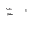
Ser i es 4 6 0 0
Universal Toxic Gas Transmitter
Operation & Maintenance Manual
Rev:
Date:
ECN#:
Part#:
4600 VerH
04/11/08
129032
087-0005
Ser i es 4 6 0 0 Ga s PLUS®
Un i v er sa l Tox i c Ga s Tr a n sm i t t er
04/2008
Co n t e n t s
I n t r o d u ct i o n
The Scott Health & Safety Gas Sensor _____________________________
Overview of Sensor Operation ___________________________________
The Sensor and Battery __________________________________________
Gas Specificty ___________________________________________________
Sensor Accuracy _________________________________________________
Sensor Response Times __________________________________________
Sensor Life ______________________________________________________
Environmental Influences to the Scott Health & Safety Sensor _______
Sensor Oxygen Requirements ____________________________________
Sensor Intrinsic Safety ___________________________________________
Sensor Handling and Disposal ___________________________________
1
1
1
2
2
2
2
3
3
4
4
GASPLUS I n st a l l a t i o n
Location Considerations _________________________________________
Physical Installation and Wiring __________________________________
Gas Transmitter or Remote Sensor Junction Box Mounting _________
Remote Sensor Mounting Without Junction Box ____________________
Typical Installation ______________________________________________
2 Wire Configuration ____________________________________________
3 or 4 Wire Configuration ________________________________________
Junction Box Electrical Installation ________________________________
Duct Adaptor Installation ________________________________________
Sensor Installation ______________________________________________
Twist and Lock Accessories _______________________________________
5
5
6
6
7
8
8
9
10
11
12
Sy st e m O p e r a t i o n
System Start-Up _________________________________________________
Alarm and Loop-Power Inhibit ____________________________________
Setting Inhibit Loop Current ______________________________________
Calibration Frequency ___________________________________________
Remote Sensor Calibration _______________________________________
Storing Sensors _________________________________________________
Zero Calibration _________________________________________________
Zero Calibration Using Ambient Air _______________________________
Using A Permeation Tube Device __________________________________
Zero Calibration Procedure ______________________________________
Span Calibration ________________________________________________
Special Span Calibration Requirements ___________________________
Span Calibration Procedure ______________________________________
Important Notes on Calibration of Sensors ________________________
Weekly Operational Response Checks ____________________________
Defining Alarm and Relay Characteristics _________________________
Acknowledging Alarm Conditions ________________________________
Failure/Alarm Indications ________________________________________
Alarms 1 and 2 __________________________________________________
Fail Indication ___________________________________________________
Sensor Strength Failure Indication ________________________________
"FFF" Indication (Missing Sensor Indicator) ________________________
Contacting Scott Health & Safety __________________________________
Technical Specifications __________________________________________
Troubleshooting _________________________________________________
Making Operational Check Gases. ________________________________
13
13
14
14
15
16
16
16
17
17
17
17
18
19
22
23
24
24
24
24
24
24
25
25
26
27
i
Ser i es 4 6 0 0 Ga s PLUS®
Un i v er sa l Tox i c Ga s Tr a n sm i t t er
Co n t e n t s Co n t i n u e d
Scott Health & Safety Warranty ___________________________________ 28
Spare Parts ______________________________________________________ 29
APPENDIX 1 - Relay Operation & Configuration ____________________ 34
Toxic Gas Quick Reference Data Supplements
ii
04/2008
Ser i es 4 6 0 0 Ga s PLUS®
Un i v er sa l Tox i c Ga s Tr a n sm i t t er
When storing the sensor "off-line", block the sensor gas hole by placing a
small piece of electrical tape over the front of the sensor (do not touch the
membrane as this will cause damage the sensor) and store the sensor in a
cool dry place (such as a refrigerator).
Should the sensor be kept off-line for a cumulative period of time exceeding 9
months, the sensor will continue to operate! Sensor battery failure does not
mean the sensor has failed and will not operate, only that it will require a 4-8
hour warm-up time upon installation. Once the sensor has "warmed-up" and
has become stable, calibration may occur as normal.
Gas Specificity
Sensor battery
failure does not
render the
sensor useless but it will require
a 4-8 hour
warm-up time
upon installation.
Each gas sensor is engineered and designed to be gas specific; however, the
very nature of electrochemical gas detection is such that the presence of
certain gases may act as an interferant to certain sensors. Each sensor can
have its own interferant(s), causing the sensor to respond electrochemically.
Scott Health & Safety has tested and documented some of the known
interferant. These are listed in an Addendum located in the back of the
manual.
Sensor Accuracy
The accuracy of a toxic gas sensing system is limited by the accuracy of the
standard used to calibrate the system. For many toxic gases, obtaining a high
accuracy standard that is suitable for field calibration use may be difficult
(about the best accuracy of gas concentration achievable is 5%, using a
permeation system with good temperature control). For this reason, no fixed
accuracy statement is possible. The accuracy of the GasPlus sensor cannot
be better than the accuracy of the calibration gas. The best accuracy to be
expected, assuming a perfect standard, is limited by the repeatability which is
±2% of span (full scale).
Sensor Response Times
Electrochemical gas sensors are optimized to give the fastest possible
response time while maintaining excellent zero stability and minimum drift
(approximate sensor response times are listed an Addendum in the back of the
manual). If the response time appears to be slow, refer to the "Weekly
Operational Checks" within the SYSTEM OPERATION section.
Sensor Life
Because applications are of such a variable nature, only experience on a given
application can truly tell what the sensor life will be. GasPlus sensors will
generally provide a minimum of 12 months of service in ambient air gas
detection applications. Extremes of humidity and temperature, and exposure
to dirty atmospheres containing particulate matter or oily vapors will decrease
sensor life. In addition, extended exposure to target or other active gases may
shorten sensor life.
In applications where only trace levels of target gas exist, except under leak
conditions, sensor life will most likely be over 18 months. While sensors may
have some, or even substantial life remaining, it is recommended that sensors
be replaced at a convenient interval between 12 and 18 months. Experience in
a given application or plant condition will determine the best replacement
frequency.
Manual #087-0005H, 04/2008
1
Ser i es 4 6 0 0 Ga s PLUS®
Un i v er sa l Tox i c Ga s Tr a n sm i t t er
Environmental Influences to the Scott
Health & Safety Sensor
Although the GasPlus transmitter is designed to operate at temperatures from
-40° to 140°F (-40° to 60°C), the operating temperature is dictated by which
gas sensor has been installed. The GasPlus Operating Parameters
Addenda (see back of manual) show the operating temperature ranges for
each sensor type. Extreme temperatures and exposure to dirty atmospheres
containing particulate matter or oily vapors can affect sensor response and
decrease sensor life.
Humidity (%RH) has the potential to affect the performance of electrochemical
sensors. Gas sensors are designed to provide stable output over a range of
humidity conditions. Continuous exposure to relative humidity conditions from
25% to 90% non-condensing RH (70% RH nominal) will not affect operation of
most sensors.
Extreme has the potential to adversely affect the operation of electrochemical
sensors. At relative humidities continuously below 25%* or above 90%,
sensors can exhibit an early loss of sensitivity after a few days to a week of
operation. This is caused by a slow loss of water (dry air) or gain of water
(moist air) from the internal sensor electrolyte. Suspending the sensor over a
jar of water for 24 hours will usually restore sensitivity to a sensor that has
"dried" out.
*The operation of H2S and HCl sensors will be affected by continuous
exposure to relative humidity conditions below 50%RH; therefore Models
4654 and 4671 low humidity sensors, respectively, are offered and should
be used when operating under these conditions.
Extremely humid or wet conditions can affect these sensors which rely on
an unobstructed gas diffusion path into the sensor. If the gas stream or
ambient air allows humidity to condense on the sensor, the water on the
membrane will cause loss of sensitivity, or slow response, or both. Once the
sensor has had a chance to dry out, normal operation should be restored. If
the source of moisture is a result of water spray or rain, a rain shield may be
installed on the sensor module to protect the sensing membrane. Keep in
mind that the some gases may chemically react with water vapor and be
converted to other species. (e.g., ammonia hydrolyzes to form ammonium
hydroxide when exposed to water vapor). In addition, other gases such as
hydrogen fluoride, are very reactive and may be absorbed on the inner surfaces
of flow tubing before reaching the sensor during calibration. Such questions
should be referred to chemists or industrial hygienists.
Sensor Oxygen Requirements
Scott Health & Safety "Traditional" and "Rock Solid Hydride and HCN"
gas sensors require a minimum of 5% oxygen for continuous operation
under ambient conditions (except the Model 80 Oxygen sensor).
Sensors operating in conditions of less than 5% oxygen will provide erroneous
or unstable concentration data.
Beyond the 5% minimum oxygen concentration requirement, all "Traditional"
Hydride sensors (Arsine, Diborane, Germane, Hydrogen Selenide, Phosphine,
Silane) require constant oxygen concentration when performing sensor
calibration. Fluctuating oxygen concentration during calibration will result in
erroneous concentration readings during system operation.
2
Manual #087-0005H, 04/2008
Ser i es 4 6 0 0 Ga s PLUS®
Un i v er sa l Tox i c Ga s Tr a n sm i t t er
Note: The above does not apply to the Scott Health & Safety Rock Solid Acid,
Cl2, O3 and ClO2 sensors. Contact Scott Health & Safety for specific
applications.
Sensor Intrinsic Safety
An intrinsically safe circuit is simply defined as "...an electrical circuit which
does not contain, or store, enough energy to cause ignition of a given explosive
atmosphere". GasPlus sensors are designed as intrinsically safe and, with the
transmitter incorporating built-in safety barrier circuitry, can be removed from
the transmitter housing within explosive environments.
Sensor Handling and Disposal
Do not attempt to disassemble the sensor in any way. The GasPlus sensor
contains various chemicals/electrolytes. Skin and eye contact should be
avoided and should be considered hazardous.
The GasPlus sensor can be disposed of as ordinary trash with no special
precautions. Incineration in a municipal/commercial incinerator poses no
hazard.
Manual #087-0005H, 04/2008
3
Ser i es 4 6 0 0 Ga s PLUS®
Un i v er sa l Tox i c Ga s Tr a n sm i t t er
Ga sPl u s I n st a l l a t i o n
Location Considerations
Prior to installing GasPlus, consideration should be given to the following items
when choosing its location:
1. Orientation - Always mount the sensor pointing downwards or horizontal
with respect to the floor.
2. Gas Density - For gases heavier than air, it is recommended that the
sensor be installed approximately 18" from floor level. In these applications
care should be taken to protect the sensors from physical damage. For gases
that are lighter than air, sensors should be installed at a high level or close to
the potential leak source.
3. Potential Gas Sources - The location and nature of potential vapor/gas
sources (e.g., pressure, amount, source, temperature, and distance) need to
be assessed.
4. Ambient Temperature & Relative Humidity - Insure that the system is
located within an area that complies with the specified operating temperature
and humidity range.
5. Vibration - Mount the transmitter and sensor in a manner that minimizes
vibration.
6. Accessibility - When determining mounting location, consider future
maintenance and calibration requirements.
7. Avoid water. Droplets adhering to the outer membrane of the sensor will
reduce or negate sensor performance. A rain shield is recommended for
outdoor installations.
8. Avoid strong electromagnetic fields. Mounting the gas transmitter near
power transformers or other strong EM fields may cause undesirable results.
9. Avoid pressure and excessive air velocity. GasPlus sensors are
designed to measure gas concentration under normal atmospheric conditions
with up to 1 LPM air flow. High air velocities will result in inaccurate
measurement and reduce sensor life.
10. Conduit Seals. Protect the transmitter electronics from moisture by
thoroughly sealing the conduit entries and tightening the cover of the
transmitter housing.
Physical Installation and Wiring
Installation of the GasPlus System requires the physical mounting of the
enclosure (see Figure 1) and connection of the power/output lines (see
Figure 2A/2B). The transmitter enclosure is provided with bolt holes in the
mounting flange for mounting. When installing GasPlus, follow these
guidelines ensuring that the area of installation is declassified if required:
STEP 1 - Make all physical connections (i.e., conduits, pipes, enclosure,
plastic spacer block, junction box, etc.).
STEP 2 - Unscrew transmitter cover.
STEP 3 - Remove 2 "stack" transmitter boards (board assembly simply
unplugs).
4
Manual #087-0005H, 04/2008
Ser i es 4 6 0 0 Ga s PLUS®
Un i v er sa l Tox i c Ga s Tr a n sm i t t er
STEP 4 - Make wire connections (18 to 22 AWG wire is recommended for
electrical connections) in accordance with Figures 2A/2B. Ensure
that proper wire gauge is used and that all wire, electrical grounds,
and sensor connections are secure and intact.
STEP 5 - Replace transmitter stack assembly.
STEP 6 - Screw transmitter cover on, ensuring a tight seal.
STEP 7 - Remove red label from the bottom of the sensor end cap.
Remote Sensor Junction Box Mounting
If the application requires that the sensor be mounted remote from the
transmitter, care should be taken to insure that all code and regulatory
requirements are met. In these applications, it is recommended that the
sensor be separated from the transmitter no more than 50'. Additional items
needed will be a junction box and sensor cable (see Figure 2B). These items
can be ordered from Scott Health & Safety. Conduit must be obtained from
your local vendor.
Remote Sensor Mounting without
Junction Box
The sensor cannot be located more than 50 feet away from the transmitter and
the stainless steel sensor housing must be electrically isolated. This
installation is not rated for hazardous locations.
Typical Power Consumption
4-20 Loop
21mA
Control circuitry
8mA
Relays
20mA (each)
Total
89mA
2.1 watts @ 24VDC
Figure 1 GasPlus Dimensions
Manual #087-0005H, 04/2008
5
Ser i es 4 6 0 0 Ga s PLUS®
Un i v er sa l Tox i c Ga s Tr a n sm i t t er
Typical Installation
Power Supply
+24VDC
4600 Gas
Transmitter
(2 Wire plus
Gnd)
Com
Loop+
Loop-
PLC, DCS or Receiver
TxG
(A)
Loop In
Mounting Beam
250 ohms
nominal
Gnd
Vg
Ground resistance
Installation Notes:
At Installation as wired above but before applying power, measure the voltage at
the transmitter between the "Loop -" terminal and the case (case terminal is
negative meter lead). If this voltage (Vgd) falls between the range -0.5V<Vgd<8V
than the installation is acceptable. If not, when power is applied barrier damage is
likely to occur due to the difference in ground potentials.
Note: At all times the transmitter enclosure must be at earth potential to prevent
a hazardous condition.
Remedies:
Improve the electrical connection between TxG and Vg until the above requirement
is met (line marked "(A)" in diagram above). If this is not possible, electrically
isolate the 4600 Transmitter enclosure from local earth ground and include the
grounding wire from the TxG terminal to the Vg connection (line marked "(A)" in
diagram above).
Terms:
TxG = Transmitter Ground
Vg = Power supply ground
Vgd = Voltage, ground differential (difference between power supply ground and
transmitter ground.
6
Manual #087-0005H, 04/2008
Ser i es 4 6 0 0 Ga s PLUS®
Un i v er sa l Tox i c Ga s Tr a n sm i t t er
Application Note:
2 Wire Configuration
Split Power Supplies
must not be used to
provide instrument
power. Any configuration
which causes more than
8 VDC to be present on
the loop(-) terminal
relative to earth will
damage the instrument.
! EMI/RFI ALERT !
When installing transmitters
equipped with internal
relays, all power lines
should be shielded. The
best practice is to run relay
switched wiring in separate
conduit from DC power and
control wiring and away
from other 110 VAC power
lines or sources of EMI/RFI,
such as variable speed
drive controls.
3 or 4 Wire Configuration
Figure 2 A- Wiring Diagram
Manual #087-0005H, 04/2008
7
Ser i es 4 6 0 0 Ga s PLUS®
Un i v er sa l Tox i c Ga s Tr a n sm i t t er
Figure 2B - Junction Box Electrical Installation
8
Manual #087-0005H, 04/2008
Ser i es 4 6 0 0 Ga s PLUS®
Un i v er sa l Tox i c Ga s Tr a n sm i t t er
IMPORTANT
Opt ional silver
dot , used on
older Rock Solid
Sensors only,
must be
orient at ed as
shown.
*
*
Optional Silver
Dot
4600 Rock Solid
Sensor
IMPORTANT
St ainless
st eel sensor
housing must
be isolat ed
f rom ground.
Figure 2C - Duct Adaptor Installation
Manual #087-0005H, 04/2008
9
Ser i es 4 6 0 0 Ga s PLUS®
Un i v er sa l Tox i c Ga s Tr a n sm i t t er
IMPORTANT!
Sensor should
always be facing
downward or
horizont al.
Cont act
fact ory for
ot her
inst allat ions.
Sensors should
never point up
at any angle.
Note: Transmitters are supplied with a ¼
turn Twist and Lock End Cap. See
"Installing Transmitter Accessories".
Figure 3 - Installing The GasPlus Sensor
Sensor Installation
Figure 3 depicts the GasPlus sensor installation. Be sure to include the
elastomeric connection pad when installing the sensor into the sensor housing.
Rotate the sensor until it locks into the alignment pin. The gas name/range
will be visible through the housing front. To ensure proper connection between
the sensor and the sensor housing, tighten the threaded sensor end cap hand
tight - do not overtighten as this could damage the elastomeric connector
or the sensor housing!
10
Manual #087-0005H, 04/2008
Ser i es 4 6 0 0 Ga s PLUS®
Un i v er sa l Tox i c Ga s Tr a n sm i t t er
Twist and Lock Accessories
Designed for quick, easy installation and removal from your GasPlus Universal
Gas Transmitter, Twist-and-Lock accessories connect directly to the standard
end cap and help make your gas detection system easier to
use.
Sensor
Transmitter
Electronics
1.362"
Rain Shield/Splashguard (Part #074-0305)
Provides protection from wet weather and hose-downs. Teflon®
construction permits use with both reactive (such as hydrogen
fluoride, hydrogen chloride, and ammonia) and non-reactive
gases. Lab tested hole geometry protects sensors from stray
water droplets.
Internal Pin
Sensor End-Cap
P/N 073-0165
Calibration Adaptor (Part # 096-2101)
Delivers calibration gas directly to the sensor face without
dilution from environmental interferences such as wind. Barb
fitting provided for tube connection to the calibration gas source
(gas cylinder, permeation device, generator).
Duct-Mount Adaptor
(Part # 096-2118-6/8 (6’ to 8” Duct) or
#096-2118-F (Flat Duct)
Monitors airflow in exhaust or ventilation ducts without drying out
your Model 4600 sensor. Able to handle flow velocities from 350
to 1000 ft. per minute. Available for use on flat ducts or 6” to 8”
diameter ducts (custom sizes also available). For use only with
transmitters configured for remote sensor and without junctionbox.
Flowcell (Part # 096-2102)
Rain Shield
Use your Model 4600 in sample draw configurations. The Teflon®
baffle prolongs sensor life by reducing air velocity past the sensor
face.
P/N 074-0305
Calibration Adaptor
P/N 096-2101
Flowcell
P/N 096-2102
P/N 096-2118-6/8
Duct Adaptor
P/N 096-2118-F
(Flat Duct)
Manual #087-0005H, 04/2008
11
Ser i es 4 6 0 0 Ga s PLUS®
Un i v er sa l Tox i c Ga s Tr a n sm i t t er
Sy st e m O p e r a t i o n
St art -Up
Not e
If " F F F "
appears after power
has been applied,
the sensor may not
be making electrical
contact with the
transmitter.
Retighten the sensor
end cap to ensure
electrical continuity.
SCOTT
INSTRUMENTS
Figure 4 - Front Panel Operations and Indications
System Start-Up
Once all transmitters (sensor, rain shield, etc.) have been assembled and
installation has been completed, recheck electrical connections to be sure
wiring is correct. Once checked, the DC supply to GasPlus may be
energized.
Once power is applied, GasPlus will initialize an LCD character display test
routine. Verify that all character segments are displayed. In addition, the
transmitter will detect and display sensor gas type (52=chlorine, 80=oxygen,
etc.) and its full scale range. Once display information is completed, GasPlus
alarm output is auto-inhibited and loop power is held at the user selected loop
inhibit level (default 4 mA) for about 30 seconds to permit sensor stabilization.
Alarm and Loop-Power Inhibit
The GasPlus transmitter's inhibit function prevents activation of alarms in
addition to holding loop power at the selected inhibit output level (see below)
during calibration. To activate (or deactivate) the inhibit function, use the
magnet and momentarily place it over the "Z" (ZERO) calibration zone.
Observe the LCD indicates the "IHB" function is active. The inhibit mode can
be manually deselected by reapplying the magnet the "Z" (ZERO) calibration
zone. GasPlus will automatically return to run mode about 9 minutes
after the last adjustment OR after 30 seconds upon reinstallation of a
sensor.
12
Manual #087-0005H, 04/2008
Ser i es 4 6 0 0 Ga s PLUS®
Un i v er sa l Tox i c Ga s Tr a n sm i t t er
Setting Inhibit Loop Current
Normally the GasPlus outputs a 4 mA current during inhibit mode. This may
be changed from 3.5 mA to 20 mA on units wired in the 2-wire configuration, or
0 to 20 mA on units wired in the 4-wire configuration (wiring configuration is
auto-sensed by the GasPlus). Inhibit outputs can be set in 0.1 mA
increments.
To set the loop current output level during inhibit mode:
Th e Ga sPl u s
Programming
Routine
Sequence:
#1 1 st Alarm
Setpoint
#2 1 st Relay
Function
#3 2 nd Alarm
Setpoint
#4 2 nd Relay
Function
#5 Inhibit Output
mA Level
STEP 1 - Place and hold the magnet over the Alarm Setpoint and Reset Zone.
In approximately 5 seconds, the transmitter will enter program mode
and display the value of the first alarm setpoint. Remove the magnet
and allow the transmitter to scroll through the programming routine
until "IHB" is displayed.
STEP 2 - Immediately following the "IHB" display message, a value (mA output
setting) will appear on the display. By holding the magnet over the
Alarm Setpoint and Reset Zone, the value will change. Momentarily
remove the magnet then reapply to reverse the direction of change.
When the desired output is displayed (i.e., 4.0 for 4 mA), remove
the magnet. The new value will be permanently stored and the next
time the inhibit function is activated, the transmitter will output at
that value.
STEP 3 - After a period of a few seconds, the GasPlus will return to normal
operation and the "IHB" flags will disappear.
Calibration Frequency
All GasPlus transmitters require calibration upon receipt from the factory, after
which, the calibration interval for each transmitter should be independently
established through a documented procedure which maintains a calibration log.
Calibration frequencies will vary depending upon individual applications. Harsh
environments will generally require more frequent calibration.
At a minimum, it is recommended that these calibration frequencies be
followed:
Zero Calibration: Upon system power-up; every 30 days or less; upon (new
or old) sensor re-connection to the transmitter. Oxygen Transmitter
exception - every 90 days.
Span Calibration: Upon system power-up (unless sensor has been precalibrated); every 90 days or less. Oxygen Transmitter exception - every 30
days.
Manual #087-0005H, 04/2008
13
Ser i es 4 6 0 0 Ga s PLUS®
Un i v er sa l Tox i c Ga s Tr a n sm i t t er
PLUS
PPM
12
Optional Flow Cell
Cl2
5 PPM
Calibration
Adaptor
Required Calibration
Equipment :
Calibration adaptor
Gas compatible
tubing (Teflon®
recommended for
acid gases (HF, HCl,
etc.)
500 cc/min flow
regulator
Calibration gas
Zero air (Nitrogen
for Oxygen Sensor)
Tygon Tubing
Teflon Tubing
NOTE:When using
calibration kit for NH3,
HCl, or Cl2, Tygon tubing
must be installed on the
barbed fitting. The Teflon
tubingthen slides into the
Tygon.
500 cc
Regulated
Flow
Span
or
Zero
Gas
Source
Figure 5 - Calibration Equipment
Calibration Reminder...
Document your calibration schedule requirements.
Maintain an organized system to prevent confusion
between calibrated and un-calibrated sensors.
Properly store all spare sensors.
Remote Sensor Calibration
The GasPlus is designed so the sensor may be removed from the transmitter
and calibrated at a remote location. Fixed gas detection installations using
this feature should utilize a documented calibration log (see "Calibration
Frequency") to determine sensor rotation schedules. In addition, spare
sensor(s) will be required so that continuous monitoring of the detection point
14
Manual #087-0005H, 04/2008
Ser i es 4 6 0 0 Ga s PLUS®
Un i v er sa l Tox i c Ga s Tr a n sm i t t er
is assured and a spare "powered" transmitter will be required to conduct the
calibration at a remote site. Prevent accidental installation of uncalibrated
sensors by marking all calibrated sensors with their last calibration date or
maintain them in an otherwise appropriate manner.
To remove and replace the GasPlus sensor:
STEP 1 - Inhibit the 4-20 mA output by momentarily placing the magnet over
the
(ZERO) calibration zone. Observe the LCD indicates the
"IHB" function is active.
STEP 2 - Unscrew the sensor end-cap and remove the sensor requiring
calibration. Removal of the sensor will drive the loop current to its
Fail value (3.5 mA).
STEP 3 - Replace the sensor with a pre-calibrated sensor and reinstall the
sensor end cap (refer to Pages 2-5). Ensure proper electrical
connection between the sensor and the transmitter has been made
(see "System Start-Up").
STEP 4 - Take the GasPlus out of inhibit mode by momentarily placing the
magnet over the (ZERO). Observe the LCD indicates the "IHB"
function is deactivated.
Storing Sensors
Proper storage of the pre-calibrated sensor is critical to ensure long term
functionality of the (spare) sensor. It is important to remember that upon
disconnection of the GasPlus sensor from the transmitter assembly, the bias
potential (required by electrochemical sensors) across the sensor's electrodes
will be maintained via the integral battery. The battery is capable of providing
up to a total of 9 months of "off-line" power (because the battery is not
rechargeable, "off-line" time is cumulative), providing proper storage procedures
are followed.
When storing the sensor "off-line", block the sensor gas hole by placing a
small piece of electrical tape over the front of the sensor (do not touch the
membrane as this will cause damage the sensor), and store the sensor in a
cool dry place (a refrigerator for example).
Should the sensor be kept off-line for a cumulative period of time
exceeding 9 months, the sensor will continue to operate! Battery failure
of the sensor does not mean the overall sensor has failed and will not operate,
only that it will require a 4-8 hour warm-up time upon installation. Once the
sensor has "warmed-up" and has become stable, calibration may occur as
normal.
Zero Calibration
The transmitter's zero is set by adjusting the loop output to 4 mA while the
sensor is exposed to air which is free of the gas being detected (and any
interferant gases which may be present).
Zero Calibration Using Ambient Air
Ambient air may only be used for the zeroing process if it is certain to be free
of both the target gas and any possible interferants; otherwise, a source zero
grade air should be used (except when zeroing an Oxygen transmitter,
which uses Nitrogen for this procedure).
Manual #087-0005H, 04/2008
15
Ser i es 4 6 0 0 Ga s PLUS®
Un i v er sa l Tox i c Ga s Tr a n sm i t t er
Using A Permeation Tube Device
! IMPORTANT !
If using the
transmitter with a
Scott/Bacharach
Hydrogen Sulfide
scrubber (part# 0962141), the scrubber
MUST be in place
prior to calibration!
When using a permeation tube device during a calibration session, it is
recommended that constant flow of zero air be established for at least 10
minutes before being hooked up to the calibration adaptor on the sensor. This
ensures that any analyte gas which may have been present from a previous
span calibration is flushed from the tubing and adaptor.
Optional Sensor Functional Test
These transmitters are designed to operate in many different environments. In
some extreme conditions, the sensor may become unresponsive to the target
gas due to continuous or excessive exposure to dust or dirt on the membrane,
or very high/low humidity conditions.
To ensure a unit continues to function, a sensor test should be considered.
Functional tests can be conducted by exposing the sensor to the target gas.
Follow all necessary safety precautions while conducting this test. The
frequency and necessity of this check is dependent upon the specific
characteristics of the site in which the sensor is located and should be
determined by the user.
Zero Calibration Procedure
To zero the GasPlus, proceed as follows:
STEP 1 - Inhibit the 4-20 mA output by momentarily placing the magnet over
the
(ZERO) calibration zone. Observe the LCD indicates the
"IHB" function is active.
! TUBING ALERT !
STEP 2 - Install the calibration adaptor or flow cell to the GasPlus transmitter
(see Figure 5). Make all appropriate tubing connections per
manufacturer recommendations. Turn on the air flow at a rate of 500
cc/min and let circulate over the sensor for 5 minutes.
STEP 3 - Zero the transmitter by using the magnet and placing it over the over
Ensure the proper
the
(ZERO) point on the transmitter body for approximately 5
tubing is used when
seconds. Remove the magnet. The display will read "CAL" then
performing span
"0.0" (the display will vary with range 0, 0.0, or 0.00).
calibration. Teflon® STEP 4 - If spanning the instrument, proceed to "Span Calibration-STEP 2"
tubing should be
OR take the GasPlus out of inhibit mode by momentarily placing the
used when
magnet over the (ZERO). Observe the LCD indicates the "IHB"
calibrating with
function is deactivated (the transmitter will automatically deactivate
hydrogen fluoride or
inhibit mode after 9 minutes).
acid gas.
Span Calibration
When calibrating the transmitter span, the concentration of the span gas
standard should be at least 50% (BUT NOT IN EXCESS OF 90%) of the
transmitter's range. In addition, if the calibration gas is not in an air balance
(nitrogen for example), do not allow the gas to flow across the sensor for more
than 5 minutes. This will deplete oxygen in the sensor and cause erroneous
readings and slow recovery to normal operation (most sensors require a
minimum of 5% oxygen for proper operation).
Special Span Calibration Requirements
Hydrides Calibration: Hydride sensors (AsH3 /Arsine, PH3 /Phosphine, B2H6
/Diborane, SiH4/Silane, GeH4 /Germane) exhibit a significant transient
response to changes of oxygen concentration. This response will not effect
the sensor's usefulness when operating in normal atmospheric breathing air.
16
Manual #087-0005H, 04/2008
Ser i es 4 6 0 0 Ga s PLUS®
Un i v er sa l Tox i c Ga s Tr a n sm i t t er
However, when calibrating a hydride sensor, hydride gases bottled in
backgrounds other than 20.9% oxygen should not be used, as the sensor will
see a change in oxygen background. For this reason, permeation tube devices
are recommended with normal air as a diluent.
Ammonia (NH3) Note: It is acceptable to use ammonia sensors in reduced
oxygen environments (down to 2%) providing that the sensor is stored within
the environment for 24 hours prior to calibration in the same environment.
Span Calibration Procedure
To span the GasPlus transmitter proceed as follows:
STEP 1 - Ensure that the transmitter inhibit feature is activated, and if using
the hydrogen sulfide scrubber (part# 096-2141), that it is in place.
STEP 2 - Verify that the span gas being used has not exceeded its expiration
date. Old or improperly stored calibrations gases can degrade
causing inaccurate calibration. A minimum gas concentration of
15% of the full scale range is required; however, a gas concentration
of a least 50% of the full scale range is recommended (BUT NOT IN
EXCESS OF 90%).
STEP 3 - Assemble the specific calibration kit to be used (i.e., permeation
tube device, bottled gas, gas generator, etc.), and make the
appropriate connections to the transmitter's calibration adaptor.
Attach the calibration adaptor to the transmitter's sensor assembly.
! IMPORTANT!
The operat ion
response check
is not int ended
t o be a
quant it at ive
measur ement
of t he
t ransmit t er 's
out put signal.
STEP 4 - Initiate gas flow and allow the span gas to flow for approximately 5
minutes at a rate of 500 cc/min. NOTE: When calibrating outdoors
on a windy day, it will be necessary to temporarily cover the holes
around the circumference of the rain shield. Otherwise, rapid air flow
caused by wind will dilute the gas standard as it enters the sensor
area. The holes need not be tightly sealed. The transmitter should
begin to respond to the calibration gas immediately. The indicated
gas concentration should slowly level off to a value (usually close to
that of the span gas concentration) and remain stable.
STEP 5 - Using the magnet, place the magnetic tip over the
(SPAN) point
on the transmitter body and hold it there. The reading will start to
slowly move either up or down. If this change in reading is moving in
the wrong direction, remove the magnet for a moment, then replace
it on the SPAN point and the reading will start to move in the
opposite direction. After 15 counts the change in reading will
become faster. Once the displayed concentration has reached the
desired reading (the concentration of the span gas being used),
remove the magnet. The GasPlus will then display the span
calibration factor which has been applied to the sensor. The
calibration factor has an inverse relationship to the amount of gain
applied to derive the correct 4-20 mA output signal. Sensors
having a calibration factor of 150 or less are approaching the
end of their useful life and should be replaced soon.
STEP 6 - Take the transmitter out of inhibit mode by momentarily applying the
magnet to the
(ZERO) point. Observe that the (2) inhibit
indication flags are no longer visible. (NOTE: The transmitter will
automatically return to run mode about 9 minutes after the last
adjustment). After calibration is complete, disconnect the
calibration system. The unit should now be operating properly and
displaying the current gas concentration.
Manual #087-0005H, 04/2008
17
Ser i es 4 6 0 0 Ga s PLUS®
Un i v er sa l Tox i c Ga s Tr a n sm i t t er
Important Notes on Calibration of Sensors
Calibration of 0-1000 PPM Methyl Iodide Sensor (CH3I)
Please note that as of March 30, 1999 Scott Health & Safety has released a
new high range CH3I sensor. There is an important calibration method that
MUST be adhered to when calibrating this sensor. Upon multiple exposures to
high concentrations of gas (>500 PPM) it begins to show increased sensitivity
for a duration of approximately 5 days. In other words, it provides a higher
output when exposed to the same concentration of gas. The increased
sensitivity varies from sensor to sensor, but is typically on the order of 30%.
After 5 days, the sensor once again shows the same sensitivity as that seen
prior to the high gas exposure. This increased sensitivity does not occur for
exposure concentrations less than or equal to 200 PPM. Therefore 3
recommendations are being made:
1. The 0-1000 PPM range sensor should not be calibrated any more
frequently than once per week.
2. The sensor should be calibrated with actual methyl iodide with a
concentration of less than 500 PPM.
3. If the sensor is exposed to a high concentration of gas it should be allowed
a recovery period of 7 days before recalibration. Alternatively, it is
suggested that a spare GasPlus sensor be kept to swap out any sensor
exposed to concentrations greater than 500 PPM. This will allow the
“exposed” sensor time to recover.
Keep in mind that exposure concentrations greater than 500 PPM methyl
iodide will be unusual. Even if the sensor were to be exposed to a high
concentration, the only side effect is increased sensitivity for 3-5 days. If
another gas leak occurs, then the sensor will simply overrespond to the gas
leak, which is safe-sided.
If you have any questions, please feel free to contact your local Regional Sales
Manager or your inside sales support contact at Bacharach-EIT.
New Mandatory Calibration Method of HF Sensors
When spanning HF sensors, using a surrogate gas such as HCl and Cl2 might
be preferred by the operator. When doing this, keep in mind that the crosscalibration factor used to adjust the span is an estimate based on the
average response of several sensors.
Cl2 (an oxidizing gas) may be used to span an HF sensor, but it is
recommended to "bump" test it by exposing the sensors briefly to
vinegar vapors to be sure its ability to respond to the acidic HF gas has
not been exhausted.
I. Using a gas generator:
STEP 1 - Attach the delivery tube from the generator to a calibration
adapter. Use the delivery tube supplied by the manufacturer or
a length of Teflon® or Tygon-clad Teflon®. Do not apply to sensor
at this time.
STEP 2 - Start the generator, being sure the flow rate is set to 0.5 lpm and the
gas concentration is set to the desired value.
STEP 3 - Allow the gas to flow through the delivery tube and calibration
adapter to let them equilibrate with the gas before connecting to the
18
Manual #087-0005H, 04/2008
Ser i es 4 6 0 0 Ga s PLUS®
Un i v er sa l Tox i c Ga s Tr a n sm i t t er
sensor. Depending on the local environment, this may take 5 to 15
minutes or longer.
STEP 4 - While waiting, check the sensor zero reading and zero it if
necessary.
STEP 5 - After sufficient time has passed for the gas delivery tube and
calibration adapter to equilibrate with the gas flowing through them,
attach the calibration adapter to the 4600 sensor end-cap (remove
the rain shield first, if there is one).
STEP 6 - After five minutes, adjust the span to agree with the concentration of
gas coming after the generator.
STEP 7 - Remove the calibration adapter, and re-install the rain shield if
necessary.
Note - Some generators1 don't have air pumps with enough power to overcome
the pressure drop of the porous diffuser plug in the calibration adapter. In this
case the diffuser must be removed prior to starting the process:
STEP 1 - With pliers or a 9/16" wrench, remove the barbed hose fitting from the
calibration adapter.
STEP 2 - Through the hole, push out the diffuser with a screwdriver or a pencil.
Put the plug in a pocket or other safe place.
STEP 3 - Replace the hose fitting and tighten.
STEP 4 - When the calibration process is finished, put the diffuser plug back
into its hole and press it until its face is flush with calibration
adapter's face.
II. Using calibration gas cylinders
STEP 1 - Attach a regulator capable of delivering 0.5 lpm gas to the cylinder.
STEP 2 - Connect the regulator output to a calibration adapter using a length of
Teflon® tubing or Tygon-clad Teflon®. Do not apply to the sensor at
this time.
STEP 3 - Be sure the porous diffuser plug is in place in its hole in the
calibration adapter.
STEP 4 - Allow the gas to flow through the delivery tube and calibration adapter
to let them equilibrate with the gas before connecting to the sensor.
Depending on the local environment, this may take 5 to 15 minutes
or longer.
STEP 5 - While waiting, check the sensor zero reading and zero it if
necessary.
STEP 6 - After the delivery tube and adapter have equilibrated with the gas,
attach the adapter to the 4600 sensor end-cap (remove the rain
shield first, if there is one.)
1
ACD's (Advanced Calibration Designs) model 300 and EC Cal Cal-2000 do not have this problem. You may suspect your generator is one
that has a weak pump if the sensor's response is "zero" or much lower than anticipated.
Manual #087-0005H, 04/2008
19
Ser i es 4 6 0 0 Ga s PLUS®
Un i v er sa l Tox i c Ga s Tr a n sm i t t er
STEP 7 - Continue the gas flow and after five minutes, adjust the span to agree
with cylinder label value.
STEP 8 - Shut off the gas, remove the calibration adapter from the end-cap,
and reinstall the rain shield if there is one.
Note - Sometimes regulators require time to adjust after changing from one gas
type to another. For example, a regulator that has been on an H2S cylinder will
have absorbed H2S, especially when it is brass. The sulfided interior will
destroy gasses such as Cl2 until enough time and gas have passed to "clean
out" the regulator. In extreme cases, it will probably be better to use a new
regulator and then reserve it exclusively for use with the particular gas (i.e.
chlorine).
20
Manual #087-0005H, 04/2008
Ser i es 4 6 0 0 Ga s PLUS®
Un i v er sa l Tox i c Ga s Tr a n sm i t t er
Weekly Operational Response Checks
It is suggested that a sensor response test should be performed
weekly to ensure the transmitter continues to respond to the
target gas. It is recommended to briefly expose the transmitter to a dose of
the calibration gas used to span the instrument. A 5 to 10 second gas stream
directed at the base of the sensor should suffice in producing a response from
the transmitter.
If response is slow (typical response time will be within 5 seconds), check the
tip of the sensor for either dirt buildup or condensation on the membrane. Both
can cause slower than normal operation. If an excessive dirt buildup is
present, the sensor is generally not repairable. If there is excessive moisture
present, the sensor may be removed to a dry area and permitted to dry. Under
such conditions, the cause of the excessive moisture should be determined
and prevented (condensing humidity, wash-downs, etc.)
Refer to the appendix for alternative methods of generating operational check
gases.
NOTE !
When det ect ing
oxygen deficiency,
t he ALARM 2
set point should
be BELOW t he
ALARM 1
set point (a
falling alarm).
GasPlus Alarms
The GasPlus transmitter permits 2 alarm setpoints and relay operation (for
those transmitters equipped with the relay option) to be specified. The
program routine sequence is:
• Present Alarm 1 setpoint
• Alarm 1 latching/non-latching status (displayed as "_LA" or "nLA" ).
• Alarm 1 energize/non-energize relay status (displayed as "_En" or "nEn")
• Present Alarm 2 setpoint
• Alarm 2 latching/non-latching status
• Alarm 2 energize/non-energize relay status
To view or change alarm setpoints and relay latching function:
STEP 1 - Place and hold the magnet over the Alarm Setpoint and Reset Zone.
In approximately 5 seconds, the transmitter will enter program mode
and display the value of the first alarm setpoint.
STEP 2 - If the magnet is held in position for longer than ½ second, the Alarm
1 setpoint will begin to change. If the magnet is removed, the
programming routine will scroll through each programmable
parameter in the sequence listed above. To change any of these
parameters, apply the magnet to the alarm setpoint zone while the
parameter is being displayed. Alarm setpoints require the magnet
be applied at the alarm setpoint zone and held in position until the
alarm setpoint value is achieved (momentarily removing the magnet
and reapplying will reverse the direction in which the values scroll).
Changing alarm relay functions (latching/non-latching, energized/
non-energized) is accomplished by momentarily applying, then
removing, the magnet to the alarm setpoint zone. All parameters will
be displayed for 7 seconds after the last alarm (setpoint zone)
activation.
Manual #087-0005H, 04/2008
21
Ser i es 4 6 0 0 Ga s PLUS®
Un i v er sa l Tox i c Ga s Tr a n sm i t t er
Defining Alarm and Relay
Characteristics
Rising Alarms are alarms which are activated whenever the gas concentration
level is equal to, or above, the alarm setpoint. Rising alarms are assigned by
setting the ALARM 2 trip point above the ALARM 1 trip point.
Falling Alarms are activated whenever a gas concentration level is equal to, or
below the alarm setpoint. Falling alarms are assigned by setting the ALARM 2
setpoint below the ALARM 1 setpoint.
Latching Alarm ("_LA" on the LCD) designates the mode of operation for the
GasPlus (or its relay if so equipped). Once the gas concentration no longer
constitutes an alarm condition, the GasPlus (or its internal relay) has to be
reset to its normal condition by applying the magnet to the alarm setpoint
zone. Also can be know as "manual reset".
Non-Latching Alarm ("nLA" on the LCD). Transmitter must be equipped with
internal alarm relays in order for this feature to be functional. Designates the
mode of operation for GasPlus (or its relay if so equipped). Once the gas
concentration no longer constitutes an alarm condition, the relay will reset to
its normal condition automatically. Also can be known as "Auto Reset".
Normally energized ("En" on the LCD). Transmitter must be equipped with
internal alarm relays in order for this feature to be functional. Designates a
relay which operates so that, under normal conditions, its contacts to the
terminal strip are closed. Such relay operation is also known as fail-safe
because the contact will open if an alarm condition is met.
Normally not energized ("nEn" on the LCD). Transmitter must be equipped
with internal alarm relays in order for this feature to be functional. Designates
a relay which operates so that, under normal conditions, its contacts to the
terminal strip are open. Such relay operation is also known as normal or
non-fail-safe because the contact will close if an alarm condition is met.
22
Manual #087-0005H, 04/2008
Ser i es 4 6 0 0 Ga s PLUS®
Un i v er sa l Tox i c Ga s Tr a n sm i t t er
Acknowledging Alarm Conditions
Transmitters whose alarm parameter has been designated as "latching"
("_LA") must be manually reset (acknowledged) once the concentration level of
the target gas exceeds that of the designated alarm setpoint, and an alarm
immunity period of 5 seconds is exceeded. To reset the transmitter,
momentarily apply, then remove, the magnet to the alarm setpoint zone.
Observe that the specific alarm (1, 2, or F) indication flag has cleared from the
main display.
Failure/Alarm Indications
Alarm activation is indicated by flags on the GasPlus LCD. The following are
conditions upon which alarm indications will be activated:
Alarms 1 and 2
Target gas concentration levels have exceeded those designated in the alarm 1
and/or 2 setpoints (see "Designating Alarm Setpoints and Relay Operation"
section).
Fail Indication
A fail indication will be displayed by both the "F" flag indicator and "FFF" on
the LCD. A Fail indication is usually a result of either a removed or poor
sensor-to-housing electrical connection or sensor failure discovered by the
self-diagnostic routine. The self diagnostic routine interrogates transmitter and
sensor memory transfer integrity and is continuously performed by the
GasPlus. Should a failure occur, transmitter mA output goes to 3.55 mA
±.05mA.
Sensor Strength Failure Indication
This flag will only appear during system calibration where the transmitter has
applied a calibration factor of less than 150. This helps indicate to the operator
that the sensor requires replacement. The "SEN" flag will remain on until
sensor is replaced. There is no effect on the transmitter's mA output.
"FFF" Indication (Missing Sensor Indicator)
This display combination is used to indicate a missing sensor or loss of
continuity between the sensor and the transmitter. Should this occur, the
transmitter's mA output goes to the Fail level (3.55 mA ±.05mA).
FFF
Alarm 1,2, and Fail relay activation
indicated by double flag ( )
Manual #087-0005H, 04/2008
23
Ser i es 4 6 0 0 Ga s PLUS®
Un i v er sa l Tox i c Ga s Tr a n sm i t t er
Scott
Health & Safety
Co n t a ct i n g
4320 Goldmine Road
Monroe, NC 28110
Scott Health & Safety may be contacted Monday through Friday
8:30 AM to 5:00 PM EST.
Phone 1-800-247-7257 • FAX 1-704-291-8340
e-mail • [email protected]
Te ch n i ca l
Sp e ci f i ca t i o n s
Repeatability: ____________________________
Linearity: _______________________________
Output: _________________________________
Max Loop Load:
2-Wire _______________________________
4-Wire _______________________________
Power: _________________________________
_____________________________________
Display: _________________________________
±2% FS
±2% FS
4-20 mA
460 ohms at 24 VDC (25 mA based)
800 ohms at 24 VDC (25 mA based)
18-30 VDC, 0.6 W in basic configuration (nominal)
1.7 W max. in 4-wire w/relays 21 mA max (4-20 loop)
3.5 digit LCD
0-100% concentration bargraph
Alarm indication
Inhibit indication
Temperature:
Sensor _______________________________
Transmitter ___________________________
LCD _________________________________
Humidity: _______________________________
Weight: _________________________________
Separated Sensor: _______________________
Alarm Relays: ____________________________
See "Capabilities Chart"
-40° to 140°F (-40° to 60°C)
-22° to 140°F (-30° to 60°C)
Up to 99%RH, non-condensing
5 lbs (2.25 Kg)
Up to 50' (15.25m)
(2) concentration,
(1) Fail 10 amp, SPDT rated @ 120 v (resistive load)
Self Diagnostic Routines: __________________ Weak sensor indication; Electronic faults; System
memory; Missing sensor; Sensor configuration
Approvals: ______________________________ UL& C-UL Classified Fire and Explosion Hazards
Class I, Div. 1, Groups B, C, & D; Class II, Groups E, F,
G; & Class III for Standard Configuration only, as
shown in Figure 1 on Page 5.
Sensor Life: _____________________________ 9 months (unpowered)
Warranties:
Transmitter ___________________________ 1 Year
Sensor _______________________________ 1 Year
24
Manual #087-0005H, 04/2008
Ser i es 4 6 0 0 Ga s PLUS®
Un i v er sa l Tox i c Ga s Tr a n sm i t t er
Tr o u b l e sh o o t i n g
When the 4600 Gas Transmitter detects a fault it drives the analog output to
3.55mA ±.05mA. In addition the front screen will display "FFF". Note that some
faults cannot be detected by the 4600 Gas Transmitter and therefore span gas
calibration is required on a regular basis to determine proper operation. Refer to
Troubleshooting Chart below for various problems that may occur during
operation.
TROUBLESHOOTING CHART
SYMPTOM
FFF Display
POSSIBLE CAUSE
Missing Sensor
Bad Elastomeric Pad
Incorrect Endcap
Transmitter does not
respond to Span Gas
Damaged Stainless
Steel Sensor Housing
Bad Elastomeric Pad
Bad Sensor
Bad or Weak
Calibration Gas
Transmitter Zero Drifts
Manual #087-0005H, 04/2008
CORRECTIVE ACTION
Tighten Endcap
Replace Pad
Confirm correct endcap
is being used.
Replace Sensor Housing
Replace Pad
Replace Sensor
Replace Gas
Source
Cover holes on
Poor Gas Delivery Endcap - Leave
Wind
one hole open.
Check Tubing for
cuts.
For Cl2 applications
Confirm Regulator/
Tubing was not used
with H2S.
For sticky gases (HF,
HCl, Cl2, SO2, BCl3,
etc.) Confirm that
Teflon Tubing is being
used.
Check Calibration Cup Diffuser is not plugged.
Interfering Gas Present Place Zero Air on Sensor
to determine if outside
gas present.
Rapid Temperature
If possible, shield sensor
Changes
from source of temperature
changes.
High Gain on Sensor
Recheck Sensor Calibration
Factor. Sensors with Low
Calibration Factors tend to
drift more.
25
Ser i es 4 6 0 0 Ga s PLUS®
Un i v er sa l Tox i c Ga s Tr a n sm i t t er
Mak ing
Op e r a t i o n a l Ch e ck
Ga se s
The following methods can be used during operational
response checks of the transmitter:
For transmitters detecting: Cl2 , ClO2 , O3 , Br2 , F2
Place a teaspoon of powdered calcium hyporchlorite in a small plastic bottle
and cap tightly. When you wish to test a sensor, simply remove the cap and
hold the mouth of the bottle near the tip of the sensor.
For transmitters detecting: HCl
Observe Extreme Caution! Place about 10 cc of concentrated hydrochloric
acid (approximately 38% HCl) into a small plastic (polyethylene) bottle.
Unscrew the cap and hold the mouth of the bottle near the tip of the sensor.
For transmitters detecting: HF
Observe Extreme Caution! Line the bottom of a small plastic (polyethylene)
bottle with 1 or 2 pieces of laboratory filter paper. Add 2-3 drops of
concentrated hydrofluoric acid (49%) and cap tightly. Unscrew the cap and
hold the mouth of the bottle near the tip of the sensor.
For transmitters detecting: HCN, SO2 , H2S
Observe Extreme Caution! Place about 10 cc of 1N sulfuric acid into a
small plastic (polyethylene) bottle. Add a few crystals of sodium sulfide to the
acid just prior to testing the sensor, since the resulting SO2 gas will quickly
dissipate. Hold the mouth of the bottle near the tip of the sensor. CAUTION:
DO NOT CAP THE BOTTLE UNTIL THE GENERATION OF GAS HAS
STOPPED, OR THE BOTTLE MAY BURST.
For transmitters detecting: NH3
Use household liquid ammonia. Hold the mouth of the bottle near the tip of the
sensor. Do not overexpose the sensor to ammonia or it will take a long time
for it to recover to zero. Also, do not splash liquid ammonia solution onto the
membrane.
! CAUTION !
USE APPROPRIATE SAFETY
PRECAUTIONS
WHEN HANDLING CHEMICALS.
ONLY TRAINED PERSONNEL
SHOULD
HANDLE ACID COMPOUNDS.
26
Manual #087-0005H, 04/2008
Ser i es 4 6 0 0 Ga s PLUS®
Un i v er sa l Tox i c Ga s Tr a n sm i t t er
Scott Health & Safety
Wa r r a n t y
GENERAL POLICY COVERAGE
The manufacturer warrants to the original purchaser and/or ultimate customer
of the manufacturer’s products that if any part(s) thereof (except for those listed
below) prove(s) to be defective in material or workmanship within 18 months
from the date of shipment or 12 months from the date of start-up, whichever
comes first. Such defective part(s) will be repaired or replaced free of charge if
shipped prepaid to the factory in a package equal to (or) original container.
Exceptions to this general warranty policy are:
Gas Sensors
Gas sensors which are part of certain products are covered by a 12-month
warranty. Should a failure occur within 12 months of shipment, the sensor will
be replaced at no charge, providing the sensor has been used and installed in
accordance with the O&M Manual recommendations. The Phosgene (COCl2)
sensor has a warranty of six (6) months.
TERMS AND CONDITIONS
All product will be returned freight prepaid and allowed if it is determined by the
manufacturer that the part(s) failed due to defective materials or workmanship.
The seller assumes no liability for consequential damages of any kind, and the
buyer by acceptance of this equipment will assume all liability for the
consequences of its use or misuse by the buyer, his employees, or others. A
defect within the meaning of this warranty in any part of any piece of equipment
shall not, when such part is capable of being renewed, repaired, or replaced,
operate to condemn such piece of equipment.
This warranty does not cover consumable items, batteries, or wear items
subject to periodic replacement including lamps and fuses.
This warranty is in lieu of all other warranties (including without limiting the
generality of the foregoing warranties of merchantability and fitness for a
particular purpose), guarantees, obligations, or liabilities expressed or implied
by the seller or its representatives and by the statute or rule of law.
This warranty is void if the instrument has been subject to misuse or abuse, or
has not been operated in accordance with instructions, or if the serial number
has been removed.
SCOTT HEALTH & SAFETY MAKES NO OTHER WARRANTY EXPRESSED
OR IMPLIED EXCEPT AS STATED ABOVE.
Ye a r 2 0 0 0
Co m p l i a n ce
The Model 4600 accepts all dates in the years after 1999 as valid dates. The
instrument's functionality, performance, and accuracy will not be affected as a
result of the run date or dates being processed, irrespective of the century.
Manual #087-0005H, 04/2008
27
Ser i es 4 6 0 0 Ga s PLUS®
Un i v er sa l Tox i c Ga s Tr a n sm i t t er
Sp a r e Pa r t s
Miscellaneous
Part #
096-2149
096-2149-1
096-2118-6/8
096-2118-F
093-0097
096-2065
077-0127
077-0120
096-1943
096-1981
096-1981-1
096-2170
096-2213
073-0165
073-0210
096-2249
096-2202
096-2203
096-2204
096-1987-1
096-1987-3
096-1942-3
096-1942-1
096-1941-1
096-1940
096-2104
096-2141
096-2146
28
Description
Separated sensor housing w/
6 feet of cable, no junction box.
For Duct Mount Adaptors
Same as 096-2149, but without
window (for condensing humidity
applications).
6-8" Curved Duct Mount Adaptor
Flat Duct Mount Adaptor
Elastomeric Connector w/ O-Ring
Heater Assembly
("P" models only)
Pump Assembly
("P" models only)
Scott Health & Safety Magnetic
Screwdriver
Sensor Rain Shield/Calibration
Adaptor (used with S.S. End Caps
073-0165 & 073-0210)
S.S. Sensor Housing-3/4" NPT
(w/ window - does not include
end cap)
Same as 096-1981, but without
window (for condensing humidity
applications).
S.S. Sensor Housing-1-1/4" NPT
(with window - does not include
end cap)
S.S. Sensor Housing-1-1/4" NPT
w/o window (for condensing
humidity applications)
S.S. End Cap
S.S. End Cap (Rock Solid)
Power Supply Board (MB)
(w/o relays)
Junction-Box (w/ 3/4" NPT
bottom) & Blind Cover
Junction-Box P.C.B. Assembly
Junction-Box Assembly
(1-1/4" Fitting w/ 50 Ft. cable)
Standard 4-20 Spare Transmitter
Assy. (3 board transmitter stack)
Relay equipped Spare Transmitter
Assy. (3 board transmitter stack)
Power Supply Board w/ Relays
Power Supply Board without
Relays
CPU Board
Display Board
Dust Filter (H2S & CO only)
(Bag of Qty. 10)
H2S Filter for HCN, NH3 & Hydride
Sensors (Bag of Qty. 5)
(5) Condensing Humidity
Membranes (for end caps 0962142 & 096-2276)
Ca l l 8 0 0 - 2 4 7 - 7 2 5 7 or Your
Loca l Sa l es Rep r esen t a t i v e
1/4 Turn Calibration
Accessories
Part #
074-0305
096-2101
096-2102
096-2105
096-2140
096-2142
096-2273
096-2276
096-2352
096-2387
Description
¼ Turn (Teflon) Rain Shield
¼ Turn Calibration Plug Assembly
(w/(1) ¼" NPT x 3/16" O.D. Barb Fitting)
¼ Turn Flowcell Assembly
(w/(2) 1/8" NPT x 3/16 O.D." Barb Fitting)
¼ Turn Sensor End Cap Assembly
¼ Turn Hydride Sensor End Cap
Assembly w/ IPA Filter (096-2916)
Condensing Humidity End Cap
¼ Turn Sensor End Cap Assembly
(Rock Solid)
Condensing Humidity End Cap
(Rock Solid)
¼ Turn Methyl Mercaptan Sensor
(4645) End Cap Assembly w/
Hydrogen Sulfide Getter Filter
(096-2323)
¼ Turn Phosgene Sensor (4650)
End Cap Assembly w/ Hydrogen
Cyanide Getter Filter (096-2386)
Manual #087-0005H, 04/2008
Ser i es 4 6 0 0 Ga s PLUS®
Un i v er sa l Tox i c Ga s Tr a n sm i t t er
Spare Parts - Sensors
Traditional
Sensors
Ammonia (NH3 )
Model 85
8-Digit Prefix...Suffix
#096-1965.........(-XXXX)
50 PPM......-0050
100 PPM......-0100*
150 PPM......-0150
250 PPM......-0250
300 PPM......-0300
500 PPM......-0500
Arsine (AsH3)
Model 65
8-Digit Prefix...Suffix
#096-1953........(-XXXX)
1000 PPB......-1000*
3 PPM.....-0003
10 PPM.....-0010
Bromine (Br2 )
Model 61
8-Digit Prefix...Suffix
#096-1949........(-XXXX)
1 PPM.....-0001*
3 PPM......-0003
5 PPM......-0005
10 PPM......-0010
15 PPM......-0015
25 PPM......-0025
30 PPM......-0030
50 PPM......-0050
100 PPM......-0100
Carbon Monoxide (CO)
Model 82
8-Digit Prefix...Suffix
#096-1962........(-XXXX)
50 PPM......-0050
100 PPM......-0100*
150 PPM......-0150
200 PPM......-0200
250 PPM......-0250
300 PPM......-0300
500 PPM......-0500
1000 PPM......-1000
Chlorine Oxidant (CI2)
Model 520X
8-Digit Prefix...Suffix
#096-2003........(-XXXX)
1 PPM......-0001
3 PPM......-0003
5 PPM......-0005*
10 PPM......-0010
Manual #087-0005H, 04/2008
Ca l l 8 0 0 - 2 4 7 - 7 2 5 7 or Your
Loca l Sa l es Rep r esen t a t i v e
Chlorine (CI2)
Model 52
8-Digit Prefix...Suffix
#096-1945.........(-XXXX)
1 PPM......-0001
3 PPM......-0003
5 PPM......-0005*
10 PPM......-0010
15 PPM......-0015
25 PPM......-0025
30 PPM......-0030
50 PPM......-0050
100 PPM......-0100
200 PPM......-0200
Chlorine (CI2)
(<35% R-H)
Model 56
8-Digit Prefix...Suffix
#096-2257.........(-XXXX)
1 PPM......-0001
3 PPM......-0003
5 PPM......-0005*
10 PPM......-0010
15 PPM......-0015
25 PPM......-0025
30 PPM......-0030
50 PPM......-0050
100 PPM......-0100
200 PPM......-0200
Chlorine Dioxide (CIO2)
Model 53
8-Digit Prefix...Suffix
#096-1946.........(-XXXX)
1 PPM......-0001*
3 PPM......-0003
5 PPM......-0005
10 PPM......-0010
15 PPM......-0015
25 PPM......-0025
30 PPM......-0030
50 PPM......-0050
100 PPM......-0100
Diborane (B2H6)
Model 67
8-Digit Prefix...Suffix
#096-1955.........(-XXXX)
1000 PPB......-1000*
2 PPM......-0002
10 PPM......-0010
Ethylene Oxide (ETO)
Model 15
8-Digit Prefix...Suffix
#096-2905.........(-XXXX)
10 PPM......-0010
Fluorine (F2)
Model 62
8-Digit Prefix...Suffix
#096-1950.........(-XXXX)
1 PPM......-0001*
3 PPM......-0003
5 PPM......-0005
10 PPM......-0010
15 PPM......-0015
25 PPM......-0025
30 PPM......-0030
50 PPM......-0050
100 PPM......-0100
Germane (GeH4)
Model 69
8-Digit Prefix...Suffix
#096-1957.........(-XXXX)
1000 PPB......-1000*
3 PPM......-0003
10 PPM......-0010
Hydrogen (H2)
Low Humidity
Model 87
8-Digit Prefix...Suffix
#096-1967.........(-XXXX)
1 %..........-0001
4 %..........-0004*
5 %..........-0005
10 %..........-0010
Hydrogen (H2)
High Humidity
Model 52
8-Digit Prefix...Suffix
#096-2712.........(-XXXX)
1 %..........-0001
4 %..........-0004*
5 %..........-0005
10 %..........-0010
Hydrogen Chloride (HCI)
Lo Humidity (<50 %)
Model 54
8-Digit Prefix...Suffix
#096-1947.........(-XXXX)
10 PPM......-0010
25 PPM......-0025*
50 PPM......-0050
100 PPM......-0100
Hydrogen Chloride (HCI)
Hi Humidity (>50 %)
Model 71
8-Digit Prefix...Suffix
#096-1958.........(-XXXX)
10 PPM......-0010
25 PPM......-0025*
50 PPM......-0050
100 PPM......-0100
Hydrogen Cyanide (HCN)
Model 64
8-Digit Prefix...Suffix
#096-1952.........(-XXXX)
10 PPM......-0010*
25 PPM......-0025
30 PPM......-0030
50 PPM......-0050
100 PPM......-0100
Hydrogen Cyanide (HCN)
Low %RH
Model 16
8-Digit Prefix...Suffix
#096-2871.........(-XXXX)
10 PPM......-0010*
25 PPM......-0025
30 PPM......-0030
50 PPM......-0050
100 PPM......-0100
Hydrogen Fluoride (HF)
Model 63
8-Digit Prefix...Suffix
#096-1951.........(-XXXX)
10 PPM......-0010*
15 PPM......-0015
25 PPM......-0025
50 PPM......-0050
100 PPM......-0100
Hydrogen Fluoride (HF)
Hi % RH (>75 %)
Model 70
8-Digit Prefix...Suffix
#096-2185.........(-XXXX)
10 PPM.........-0010*
15 PPM.........-0015
25 PPM.........-0025
50 PPM.........-0050
100 PPM.........-0100
Hydrogen Selenide (H2Se)
Model 89
8-Digit Prefix...Suffix
#096-1968.........(-XXXX)
1000 PPB......-1000*
10 PPM......-0010
29
Ser i es 4 6 0 0 Ga s PLUS®
Un i v er sa l Tox i c Ga s Tr a n sm i t t er
Tr a d i t i on a l Sen sor s
continued:
Hydrogen Sulfide (H2S)
Hi Humidity (>50 %)
Model 81
8-Digit Prefix...Suffix
#096-1961.........(-XXXX)
10 PPM......-0010
25 PPM......-0025
50 PPM......-0050*
100 PPM......-0100
200 PPM......-0200
Hydrogen Sulfide (H2S)
Lo Humidity (<50 %)
Model 72
8-Digit Prefix...Suffix
#096-1959.........(-XXXX)
10 PPM......-0010
25 PPM......-0025
50 PPM......-0050*
100 PPM......-0100
200 PPM......-0200
Hydrogen Sulfide (H2S)
w/ Low Methanol
Sensitivity
Model 21
8-Digit Prefix...Suffix
#096-2751.........(-XXXX)
25 PPM......-0025
50 PPM......-0050
100 PPM.....-0100
200 PPM.....-0200
Methanol (CH3OH)
Model 59
8-Digit Prefix...Suffix
#096-2148.........(-XXXX)
500 PPM.....-0500
Methyl Hydrazine (MMH)
Model 35
8-Digit Prefix...Suffix
#096-2423........(-XXXX)
50 PPM......-0050
Methyl Iodide (CH3 I)
Model 44
8-Digit Prefix...Suffix
#096-2188........(-XXXX)
25 PPM......-0025
30
Methylene Chloride
(CH2 CI2)
Model 34P
8-Digit Prefix...Suffix
#096-2189.........(-XXXX)
200 PPM......-0200
Methyl Mercaptan
(CH3SH)
Model 46
8-Digit Prefix...Suffix
#096-2348.........(-XXXX)
3 PPM......-0003
Model 45 (w/ Getter)
#096-2348.........(-XXXX)
5 PPM......-0005
Nitric Oxide (NO)
Model 86
8-Digit Prefix..Suffix
#096-1966........(-XXXX)
25 PPM......-0025
50 PPM......-0050*
100 PPM......-0100
500 PPM .....-0500
Nitrogen Dioxide (NO2)
Model 84
8-Digit Prefix..Suffix
#096-1964........(-XXXX)
10 PPM......-0010*
25 PPM......-0025
50 PPM......-0050
100 PPM......-0100
250 PPM ......-0250
Nitrogen Trifluoride (NF3)
Model 33P
8-Digit Prefix..Suffix
#096-2099........(-XXXX)
10 PPM......-0010
20 PPM......-0020
Ca l l 8 0 0 - 2 4 7 - 7 2 5 7 or Your
Loca l Sa l es Rep r esen t a t i v e
Ozone (O3)
Model 60
8-Digit Prefix..Suffix
#096-1948........(-XXXX)
1 PPM......-0001*
2 PPM......-0002
3 PPM......-0003
5 PPM......-0005
10 PPM......-0010
15 PPM......-0015
25 PPM......-0025
30 PPM......-0030
50 PPM......-0050
100 PPM......-0100
Oxygen (O2)
Model 80
8-Digit Prefix...Suffix
#096-1960........(-XXXX)
10 %..........-0010
25 %..........-0025*
Phosgene (COCl2)
Model 49
8-Digit Prefix..Suffix
#096-2235........(-XXXX)
1 PPM......-0001
Model 50 (w/ Getter)
8-Digit Prefix..Suffix
#096-2235........(-XXXX)
2 PPM......-0002
Phosphine (PH3)
Model 66
8-Digit Prefix..Suffix
#096-1954........(-XXXX)
1000 PPB......-1000*
3 PPM......-0003
10 PPM......-0010
Silane (SiH4)
Model 68
8-Digit Prefix..Suffix
#096-1956.......(-XXXX)
1000 PPB.....-1000*
10 PPM.....-0010
25 PPM.....-0025
Sulfur Dioxide (SO2)
High % RH
Model 83
8-Digit Prefix..Suffix
#096-1963........(-XXXX)
10 PPM......-0010*
15 PPM......-0015
25 PPM......-0025
50 PPM......-0050
100 PPM......-0100
200 PPM......-0200
500 PPM......-0500
Sulfur Dioxide (SO2)
Low %R-H
Model 75
8-Digit Prefix..Suffix
#096-2359........(-XXXX)
10 PPM......-0010*
15 PPM......-0015
25 PPM......-0025
50 PPM......-0050
100 PPM......-0100
200 PPM......-0200
500 PPM......-0500
Tetraethoxysilane (TEOS)
Model 58
8-Digit Prefix..Suffix
#096-2381........(-XXXX)
50 PPM......-0050
Vinyl Chloride Monomer
(VCM)
Model 73
#096-2404 (20 PPM)
Manual #087-0005H, 04/2008
Ser i es 4 6 0 0 Ga s PLUS®
Un i v er sa l Tox i c Ga s Tr a n sm i t t er
Spare Parts - Sensors
Rock Sol i d Sen sor s
Ca l l 8 0 0 - 2 4 7 - 7 2 5 7 or Your Loca l
Sa l es Rep r esen t a t i v e
R.S. Arsine (AsH 3 )
Low Humidity
Model 36
8-Digit Prefix...Suffix
#096-2457.........(-XXXX)
1 PPM.......-0001
3 PPM.......-0003
5 PPM.......-0005
500 PPB.....-0500*
R.S.Boron Trichloride
(BCl 3) Low Humidity
Model 26
8-Digit Prefix...Suffix
#096-2634.........(-XXXX)
1 PPM.......-0001
3 PPM.......-0003
5 PPM.......-0005*
10 PPM.......-0010
R.S. Chlorine (CI 2 )
Low Humidity
Model 22
8-Digit Prefix...Suffix
#096-2247.........(-XXXX)
1 PPM.......-0001
3 PPM.......-0003
5 PPM.......-0005*
10 PPM.......-0010
15 PPM.......-0015
20 PPM.......-0020
25 PPM.......-0025
30 PPM.......-0030
R.S.Diborane
(B 2H 6) Low Humidity
Model 42
8-Digit Prefix...Suffix
#096-2463.........(-XXXX)
1 PPM.......-0001*
2 PPM.......-0002
3 PPM.......-0003
5 PPM.......-0005
10 PPM.......-0010
500 PPB.......-0500
R.S. Arsine (AsH 3 )
High Humidity
Model 37
8-Digit Prefix...Suffix
#096-2458.........(-XXXX)
1 PPM.......-0001
3 PPM.......-0003
5 PPM.......-0005
500 PPB.....-0500*
R.S.Boron Trichloride
(BCl 3 ) High Humidity
Model 27
8-Digit Prefix...Suffix
#096-2635.........(-XXXX)
1 PPM.......-0001
3 PPM.......-0003
5 PPM.......-0005*
10 PPM.......-0010
R.S. Chlorine (CI 2 )
High Humidity
Model 24
8-Digit Prefix...Suffix
#096-2295.........(-XXXX)
1 PPM.......-0001
3 PPM.......-0003
5 PPM.......-0005*
10 PPM.......-0010
15 PPM.......-0015
20 PPM.......-0020
25 PPM.......-0025
30 PPM.......-0030
R.S.Diborane
(B 2H 6 ) High Humidity
Model 43
8-Digit Prefix...Suffix
#096-2464.........(-XXXX)
1 PPM.......-0001*
2 PPM.......-0002
3 PPM.......-0003
5 PPM.......-0005
10 PPM.......-0010
500 PPB.......-0500
R.S. Bromine (Br 2 )
Low Humidity
Model 98
8-Digit Prefix...Suffix
#096-2366.........(-XXXX)
1 PPM.......-0001*
3 PPM.......-0003
5 PPM.......-0005
10 PPM.......-0010
15 PPM.......-0015
20 PPM.......-0020
25 PPM.......-0025
30 PPM.......-0030
R.S.Boron Trifluoride
(BF3) Low Humidity
Model 28
8-Digit Prefix...Suffix
#096-2636.........(-XXXX)
1 PPM.......-0001*
3 PPM.......-0003
5 PPM.......-0005
10 PPM.......-0010
R.S. Chlorine Dioxide
(CIO 2 ) Low Humidity
Model 57
8-Digit Prefix...Suffix
#096-2283.........(-XXXX)
1 PPM.......-0001*
3 PPM.......-0003
5 PPM.......-0005
10 PPM.......-0010
15 PPM.......-0015
20 PPM.......-0020
25 PPM.......-0025
30 PPM.......-0030
R.S.Fluorine (F 2 )
Low Humidity
Model 17
8-Digit Prefix...Suffix
#096-2846.........(-XXXX)
1 PPM.......-0001
3 PPM.......-0003
5 PPM.......-0005*
10 PPM.......-0010
15 PPM.......-0015
20 PPM.......-0020
25 PPM.......-0025
30 PPM.......-0030
R.S. Bromine (Br 2 )
High Humidity
Model 99
8-Digit Prefix...Suffix
#096-2367.........(-XXXX)
1 PPM.......-0001*
3 PPM.......-0003
5 PPM.......-0005
10 PPM.......-0010
15 PPM.......-0015
20 PPM.......-0020
25 PPM.......-0025
30 PPM.......-0030
R.S.Boron Trifluoride
(BF 3) High Humidity
Model 29
8-Digit Prefix...Suffix
#096-2637.........(-XXXX)
1 PPM.......-0001*
3 PPM.......-0003
5 PPM.......-0005
10 PPM.......-0010
R.S. Chlorine Dioxide
(CIO 2 ) High Humidity
Model 78
8-Digit Prefix...Suffix
#096-2315.........(-XXXX)
1 PPM.......-0001*
3 PPM.......-0003
5 PPM.......-0005
10 PPM.......-0010
15 PPM.......-0015
20 PPM.......-0020
25 PPM.......-0025
30 PPM.......-0030
R.S.Fluorine (F 2)
High Humidity
Model 18
8-Digit Prefix...Suffix
#096-2847.........(-XXXX)
1 PPM.......-0001
3 PPM.......-0003
5 PPM.......-0005*
10 PPM.......-0010
15 PPM.......-0015
20 PPM.......-0020
25 PPM.......-0025
30 PPM.......-0030
Manual #087-0005H, 04/2008
31
Ser i es 4 6 0 0 Ga s PLUS®
Un i v er sa l Tox i c Ga s Tr a n sm i t t er
Rock Sol i d Sen sor s
continued:
Ca l l 8 0 0 - 2 4 7 - 7 2 5 7 or Your Loca l
Sa l es Rep r esen t a t i v e
R.S. Hydrogen Bromide
(HBr) Low Humidity
Model 94
8-Digit Prefix...Suffix
#096-2334.........(-XXXX)
1 PPM.......-0001
3 PPM.......-0003
5 PPM.......-0005*
10 PPM.......-0010
15 PPM.......-0015
20 PPM.......-0020
25 PPM.......-0025
30 PPM.......-0030
R.S.Hydrogen Cyanide
(HCN) Low Humidity
Model 20
8-Digit Prefix...Suffix
#096-2724.........(-XXXX)
1 PPM.......-0001
2 PPM.......-0002
3 PPM.......-0003
5 PPM.......-0005
10 PPM.......-0010*
R.S.Ozone (O 3 )
Low Humidity
Model 76
8-Digit Prefix...Suffix
#096-2377.........(-XXXX)
1 PPM.......-0001*
3 PPM.......-0003
5 PPM.......-0005
10 PPM.......-0010
15 PPM.......-0015
20 PPM.......-0020
25 PPM.......-0025
30 PPM.......-0030
R.S. Sulfur Dioxide (SO 2 )
High Humidity
Model 97
8-Digit Prefix...Suffix
#096-2337.........(-XXXX)
1 PPM.......-0001
3 PPM.......-0003
5 PPM.......-0005
10 PPM.......-0010*
15 PPM.......-0015
20 PPM.......-0020
25 PPM.......-0025
30 PPM.......-0030
R.S. Hydrogen Bromide
(HBr) High Humidity
Model 95
8-Digit Prefix...Suffix
#096-2335.........(-XXXX)
1 PPM.......-0001
3 PPM.......-0003
5 PPM.......-0005*
10 PPM.......-0010
15 PMM.......-0015
20 PPM.......-0020
25 PPM.......-0025
30 PPM.......-0030
R.S.Hydrogen Cyanide
(HCN) High Humidity
Model 19
8-Digit Prefix...Suffix
#096-2785.........(-XXXX)
1 PPM.......-0001
2 PPM.......-0002
3 PPM.......-0003
5 PPM.......-0005
10 PPM.......-0010*
R.S.Ozone (O 3 )
High Humidity
Model 77
8-Digit Prefix...Suffix
#096-2378.........(-XXXX)
1 PPM.......-0001*
3 PPM.......-0003
5 PPM.......-0005
10 PPM.......-0010
15 PPM.......-0015
20 PPM.......-0020
25 PPM.......-0025
30 PPM.......-0030
R.S.Silicon Tetrafluoride
(SiF4) Low Humidity
Model 30
8-Digit Prefix...Suffix
#096-2638.........(-XXXX)
1 PPM.......-0001
3 PPM.......-0003*
5 PPM.......-0005
R.S. Hydrogen Chloride
(HCl) Low Humidity
Model 92
8-Digit Prefix...Suffix
#096-2332.........(-XXXX)
1 PPM.......-0001
3 PPM.......-0003
5 PPM.......-0005
10 PPM.......-0010
15 PPM.......-0015
20 PPM.......-0020
25 PPM.......-0025*
30 PPM.......-0030
R.S.Hydrogen Fluoride
(HF) Low Humidity
Model 90
8-Digit Prefix...Suffix
#096-2330.........(-XXXX)
1 PPM.......-0001
3 PPM.......-0003
5 PPM.......-0005*
10 PPM.......-0010
15 PPM.......-0015
20 PPM.......-0020
25 PPM.......-0025
30 PPM.......-0030
R.S. Phosphine (PH 3 )
Low Humidity
Model 38
8-Digit Prefix...Suffix
#096-2459.........(-XXXX)
1 PPM.......-0001
3 PPM.......-0003
5 PPM.......-0005
500 PPB.......-0500*
R.S. Hydrogen Chloride
(HCl) High Humidity
Model 93
8-Digit Prefix...Suffix
#096-2333.........(-XXXX)
1 PPM.......-0001
3 PPM.......-0003
5 PPM.......-0005
10 PPM.......-0010
15 PPM.......-0015
20 PPM.......-0020
25 PPM.......-0025*
30 PPM.......-0030
R.S.Hydrogen Fluoride
(HF) High Humidity
Model 91
8-Digit Prefix...Suffix
#096-2331.........(-XXXX)
1 PPM.......-0001
3 PPM.......-0003
5 PPM.......-0005*
10 PPM.......-0010
15 PPM.......-0015
20 PPM.......-0020
25 PPM.......-0025
30 PPM.......-0030
32
R.S. Phosphine (PH 3 )
High Humidity
Model 39
8-Digit Prefix...Suffix
#096-2460.........(-XXXX)
1 PPM.......-0001
3 PPM.......-0003
5 PPM.......-0005
500 PPB.......-0500*
R.S. Sulfur Dioxide (SO 2 )
Low Humidity
Model 96
8-Digit Prefix...Suffix
#096-2336.........(-XXXX)
1 PPM.......-0001
3 PPM.......-0003
5 PPM.......-0005
10 PPM.......-0010*
15 PPM.......-0015
20 PPM.......-0020
25 PPM.......-0025
30 PPM.......-0030
R.S.Silicon Tetrafluoride
(SiF 4) High Humidity
Model 32
8-Digit Prefix...Suffix
#096-2639.........(-XXXX)
1 PPM.......-0001
3 PPM.......-0003*
5 PPM.......-0005
R.S.Tungsten
Hexafluoride (WF 6 ),
Low Humidity
Model 23
8-Digit Prefix...Suffix
#096-2632.........(-XXXX)
1 PPM.......-0001*
3 PPM.......-0003
5 PPM.......-0005
R.S.Tungsten
Hexafluoride (WF 6 ),
High Humidity
Model 25
8-Digit Prefix...Suffix
#096-2633.........(-XXXX)
1 PPM.......-0001*
3 PPM.......-0003
5 PPM.......-0005
Manual #087-0005H, 04/2008
Ser i es 4 6 0 0 Ga s PLUS®
Un i v er sa l Tox i c Ga s Tr a n sm i t t er
Ap p e n d i x 1
Relay Operation and Configuration
Summary
The 4600 and 4688-IR offer multiple relay configurations. Although this
provides customers with a lot of flexibility, it has also caused some confusion.
This tech tip defines and explains these configurations.
Position
Position describes the relay's state when it is inactivated. Normally open (NO)
relays represent a break in the circuit; the circuit is completed when the relay
is activated. In contrast, with a normally closed (NC) relay the circuit is broken
when the relay is activated. Note that a relay's position (open or closed) is
independent of its activation mechanism (energized or de-energized).
Normally Open
Normally Closed
The 4600 and the 4688-IR can operate in either NO or NC configurations.
Activation Mechanism
Activation mechanism describes how the relay is activated (i.e., by removing
power to the coil or by powering the coil). The coil of a normally energized
relay (also called a fail-safe relay) is powered in the inactivated state; activation
removes power to the coil. In contrast, the coil of a normally de-energized
relay (also called a non-fail-safe relay) is not powered in the inactivated state.
A normally energized, normally-closed relay provides a high level of security by
opening either when it is activated or when the instrument loses power. The
4600 and 4688-IR allow users to choose an activation method for each relay.
Reset Mode
The reset mode describes how a relay is reset. A non-latching relay
automatically resets itself when the condition that caused its activation ends.
In contrast, a latching relay requires some form of operator acknowledgment
before it can be reset. The 4600 and 4688-IR allow users to choose a reset
mode for each alarm relay.
Single and Double Pole
The number of poles refers to the number of contacts available from a single
relay. Single-pole (SP) relays provide 1 contact, while double-pole (DP) relays
provide 2 contacts (that operate identically).
Manual #087-0005H, 04/2008
33
Ser i es 4 6 0 0 Ga s PLUS®
Un i v er sa l Tox i c Ga s Tr a n sm i t t er
Single Pole
Double Pole
The 4600 and 4688-IR relays are all single pole (note that the high alarm on the
5300 is a double-pole relay).
Single and Double Throw
The number of throws refers to the number of contact positions available. The
contacts on single-throw (ST) relays operate in normally open mode or
normally closed mode, but not both. The contacts on double-throw (DT) relays
operate in both normally open and normally closed modes. Note that a singlethrow relay only requires 2 terminal block positions (common and NC or NO
output) whereas a double-throw relay requires 3 terminal block positions
(common, NC output, NO output).
Single Throw
Double Throw
or
Although the 4600 and 4688-IR relays are double-throw, only 2 positions are
available on the terminal block (due to space limitations). Thus the relays are
effectively single-throw, and must be ordered in NO or NC configuration.
Summary of 4600 and 4688-IR Features
The 4600 and 4688-IR provide 2 SPST alarm relays and 1 SPST fail relay. The
relays can be either NO or NC; however, the position must be specified when
the instrument is ordered. All relays can be set normally energized or normally
de-energized at the instrument, and the relays can be set latching or nonlatching.
34
Manual #087-0005H, 04/2008
Ser i es 4 6 0 0 Ga s PLUS®
Un i v er sa l Tox i c Ga s Tr a n sm i t t er
Manual #087-0005H, 04/2008
35