1
Multifuge® 1 S / 1 S-R
Instruction Manual
How to use this manual
Use this manual to get acquainted with your centrifuge and its accessories.
This manual helps you to avoid inappropriate handling. Make sure to keep it close to the centrifuge.
A manual that is not kept handy cannot provide
protection against improper handling and thus
against damage to persons and objects.
The manual comprises chapters on
• Safety regulations
• Instrument description
• Transportation and hook-up
• Rotor program and accessories
• Use of the centrifuge
• Maintenance and care
• Troubleshooting
• Technical data
• Index
Overleaf you will find a graphic
representation of the control panel
with a survey of the most important
functions
Please fold out
acceleration
profiles
deceleration
profiles
speed/RCF
program selection
(only for instruments with refrigeration unit)
temperature
Quick run
run time
open lid
stop
start
"set" keys
Bucket selection
rpm/RCF
switch key
display
pre-temperature-regulation
"set" keys
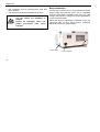
Before switching on the centrifuge
please read this manual
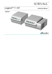
The mains switch is located on the right-hand
side panel.
Pressed up
= ON
I
Pressed down = OFF 0
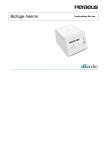
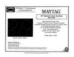
Control panel of the Multifuge® 1 S / 1 S-R
Display panels
Program selection
key 1 - 4 :
store or recall programs.
acceleration profiles
(1= slowest ...... 9= fastest)
permanent display: acceleration profile last set 1- 9
Deceleration profiles
(1= slowest ...... 9= fastest)
permanent display: deceleration profile last set 1- 9
Speed / RCF
run:
end:
lid open:
(before start)
lid closed:
error code:
current value of speed or RCF after activation of
switch key
"End"
"OPEN"
"Lift Lid" (if lid is not automatically lifted off)
"0" with flashing point
(rotor not yet identified)
will flash in display
Run time
time selection:
- remaining run time to 0
continuous operation (hld):
- run time passed (in hours, minutes)
quick run:
- run time passed (as long as button is held;
in minutes and seconds)
Temperature*
run:
current sample temperature in °C
(in temperature equilibrium)
* only for instruments with refrigeration unit
Keys
start :
stop :
open lid:
quick run:
rpm/RCF
switch:
bucket set.:
pretemp :
"set" keys:
normal start of the centrifuge
manual stop of a run
open lid
(possible only with the instrument switched on)
short-term operation of the centrifuge as long as
key remains pressed
switching between rpm and RCF display
Setting of the bucket number
Pre-temp-function*
stepwise increase/decrease of setpoint values
Short pressing of any of the "set" keys: switch from current to preset
value, signaled by flashing display.
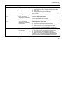
Error codes (troubleshooting see chapter "Troubleshooting"):
E-19: Unpermissible rotor
E-20: Rotor not identified
E-29: Motor or rotor blocked
E-31: Overtemperature in motor
E-32: Overtemperature in electronic
E-33: Excessive pressure in the refrigeration unit
E-34: Overvoltage
E-35: Overcurrent
Lift Lid : Smoothly lift the lid
rotor:
set speed higher than permissible speed of
the rotor
bAL :
imbalance
Contents
Contents
For your safety............................................ 3
Proper use................................................................ 3
Improper use ............................................................ 3
Centrifuging hazardous materials ............................ 3
Handling the centrifuge ............................................ 4
Conformity to current standards............................... 5
Safety instructions in this manual ............................ 5
The Multifuge® 1 S / 1 S-R .......................... 7
Description ............................................................... 7
Safety systems......................................................... 8
Parts supplied .......................................................... 8
Function and features .............................................. 9
Before use................................................. 13
Centrifuge transport and installation ...................... 13
Proper location ....................................................... 13
Main connection ..................................................... 14
Rotors and accessories ........................... 15
Rotors for the Multifuge® 1 S.................................. 16
Rotors for the Multifuge® 1 S-R.............................. 20
Handling the rotor................................................... 29
Aerosol-tight operation ....................................... 32
Checking of aerosol-tight bio-containment......... 36
Operation .................................................. 37
Switching on the centrifuge .................................... 37
Actuating the lid...................................................... 37
Opening the lid ................................................... 37
Closing the lid ..................................................... 37
Installing the rotor................................................... 38
Loading the rotor .................................................... 39
Maximum loading ............................................... 39
Filling the centrifuge tubes ................................. 40
Maximum permissible load difference ................ 40
Inserting the centrifuge tubes ............................. 41
Entering parameters............................................... 43
Deceleration curves ............................................... 43
Switching from speed to RCF display .................... 43
Bucket selection for swinging bucket rotors........... 43
Selecting speed...................................................... 44
Entering the RCF value.......................................... 44
More about the RCF value ................................. 45
Selecting run time .................................................. 45
Run time selection .............................................. 45
Continuous operation ......................................... 46
Extended time mode........................................... 46
Selecting the temperature ...................................... 47
Pretemp function .................................................... 47
Starting the centrifuge ............................................ 48
1
Contents
Imbalance display................................................... 48
Changing the settings during the run ..................... 48
Stopping the centrifuge .......................................... 49
Stopping with preset run time ............................. 49
Stopping with continuous operation ................... 49
Temperature control during standby ...................... 49
Working with programs........................................... 50
Program display.................................................. 50
Entering/changing a program ............................. 50
Centrifuging with a program ............................... 50
”Quick Run” ............................................................ 51
Removing the rotor................................................. 51
Audible alarm ......................................................... 52
Turning off the centrifuge ....................................... 52
Maintenance and care .............................. 53
Maintenance to be performed by the customer ..... 53
Cleaning.............................................................. 53
Disinfection ......................................................... 54
Decontamination................................................. 56
Autoclaving ......................................................... 56
The KENDRO service offer .................................... 57
Warranty conditions................................................ 57
2
Troubleshooting ....................................... 59
Emergency lid release............................................ 59
Error troubleshooting.............................................. 61
Contacting Kendro Service..................................... 70
Technical Data .......................................... 71
Electrical connections / fuses ................................. 73
Appendix ................................................... 75
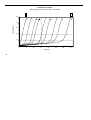
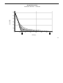
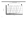
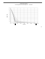
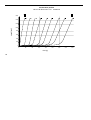
Acceleration and deceleration profiles ................... 75
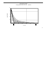
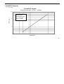
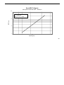
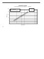
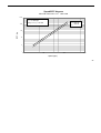
Speed/RCF diagrams............................................. 87
Index .......................................................... 93
For your safety
For your safety
Proper use
Heraeus centrifuges are manufactured according to
current technical standards and regulations. Nonetheless, centrifuges may pose danger to individuals and
surrounding if
The centrifuge is designed to separate liquidsuspended materials having different densities and
particle size, respectively (maximum sample density is
1.2 g/cm³ {ml} at maximum speed).
• they are not used as designed
Improper use
• they are operated by untrained personnel
• their design is improperly changed
• the safety instructions are not followed
Therefore, personnel involved with operation and
maintenance of the centrifuge must read and follow
the safety instructions.
In addition, the pertinent regulations for prevention of
accidents must be strictly followed.
This manual is an integral part of the centrifuge assembly and must be kept close at
hand at all times.
When damages to the power cord or at
casing are noticed the centrifuge must
to be set out of operation!
During a run, a safety zone of 30 cm around the centrifuge must be maintained where neither persons nor
hazardous materials may be present.
The centrifuge may cause harm to its user or other
persons or may damage goods if safety measures are
not followed:
Centrifuging hazardous materials
• The centrifuge is neither made inert, nor is it explosion-proof. Therefore never use the centrifuge in an
explosion-prone environment.
• Do not centrifuge explosive or flammable substances. The same holds for substances prone to
react violently with each other.
3
For your safety
• Do not centrifuge toxic or radioactive substances or
pathogenic microorganisms without suitable safety
systems.
If microbiological samples of risk group II (according
to "Laboratory Bio-safety Manual" of WHO) are being centrifuged, aerosol-tight bio-seals have to be
used.
For materials in a higher risk group, more than one
precaution is required.
• You may use the centrifuge only with a properly
loaded rotor. You must not overload the rotor.
• Strictly follow the rules and regulations for cleaning
and disinfection
• If the rotor or the rotor lid shows signs of corrosion
or wear, you must stop using it.
• Never open the lid manually if the rotor is still turning.
• Should toxins or pathogenic substances enter the
centrifuge or its parts, you must perform appropriate
procedures for disinfection (see "Maintenance and
care – Disinfection").
• You may use the emergency lid release only in
case of emergency, e.g. during an interruption of
power supply
(see chapter "Troubleshooting").
• Strongly corrosive substances that may cause
damage to materials and reduce the mechanical
strength of the rotor may be centrifuged only inside
protective tubes.
• Never use the centrifuge if the front panel has been
partially or totally removed.
Handling the centrifuge
• Use only original accessories for the centrifuge. The
only exceptions are common glass or plastic centrifuge tubes if they are approved for the rotor speed
and RCF values.
• Never use the centrifuge unless the rotor is properly
installed.
4
• Never use the centrifuge with an opened lid.
• Changes in mechanical or electrical components of
the centrifuge may only be carried out by individuals
authorized by Kendro Laboratory Products.
For your safety
Conformity to current standards
Safety instructions in this manual
Heraeus centrifuges are manufactured and tested
according to the following standards and regulations:
This symbol denotes potential hazards to
persons.
- For all voltages
This symbol denotes potential damage to
the centrifuge or parts in its immediate
surroundings.
• IEC 61010
- For 120 V only
•
General comments are marked with this
symbol.
In addition, you are asked to adhere to the pertinent
regulations, in Germany
- For 230 V only
•
• Regulations for prevention of accidents BGV A2
• Regulations for prevention of accidents VBG 5
• Regulations for prevention of accidents VBG 7z
- with cooled devices additionally
Please get acquainted with the details of the test standards from the technical data.
• Regulations for prevention of accidents BGV D4
5
For your safety
Notes
6
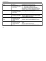
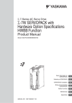
Description of the Multifuge®
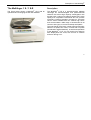
The Multifuge® 1 S / 1 S-R
Description
®
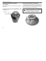
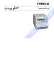
The figure below shows a Multifuge 1 S-R with an
opened lid and a swinging bucket rotor installed.
The Multifuge® 1 S-R is a general-purpose tabletop
centrifuge for biotechnological and pharmaceutical
research that moves high capacity centrifugation onto
the fast track. It spins more tubes at higher RCFs more
rapidly than competitive instruments and can process
nominally 1.6 liters of sample in a single run. There are
various rotors available that can achieve high RCFs
and accommodate a wide range of accessories for all
common tube types, micro titer and deep well plates.
The user-friendly "EASYset" control panel permits easy
selection of speed, RCF value, run time and run profile
(acceleration and deceleration), as well as temperature
of the Multifuge® 1 S-R. You can switch from speed to
RCF display and vice versa, with a touch of a button
and even during a run.
7
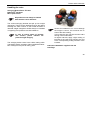
Description of the Multifuge®
Safety systems
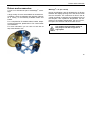
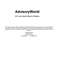
Parts supplied
The Multifuge® is equipped with a number of safety
systems:
Accessories supplied with the centrifuge are:
• Housing and lid are constructed of 6 mm steel.
− power cord
• Lid with window
• Lid lock with safety check
You can only open the centrifuge lid when the
power is turned on and the rotor has come to a
stop. You can only start the centrifuge if the lid is
properly locked.
• Automatic rotor identification
• Electronic imbalance detection as a function of rotor
(SMARTspinTM)
Do not tamper with the safety
systems!
8
− a special wrench for securing the rotor
(As seen in the picture)
− condensed operating instructions
− corrosion protective oil
The printed documents consist of the delivery notes
and this Manual.
Description of the Multifuge®
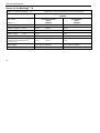
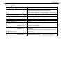
Function and features
Basic unit/ function
Description / feature
Cabinet / frame
Galvanized steel
Chamber
Stainless steel * (Multifuge 1S: coated steel)
Drive
Brushless induction drive
Key pad and display
Key pad and display elements covered by an easy-care continuous surface
Control
Microprocessor driven by "EASYset"
Main memory
Recalls last run parameters
Program memory
Data are stored until new values are entered.
Advanced features
RCF-programming, quick run, pre-temp *, temperature control during standby
Acceleration and deceleration profiles
9 acceleration and 9 deceleration profiles
Rotor identification
Automatic
TM
SMARTspin
imbalance detection system
Electronic, effective as a function of rotor and speed
Soft touch lid lock
Motor assisted lid locking
(* only with refrigeration unit)
9
Description of the Multifuge®
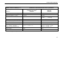
The EASYset user interface
Function
Feature
Program memory keys
Freely programmable
Acceleration / deceleration profile
1 = slowest, ... 9 = fastest acceleration / deceleration curve
Setting speed by rpm
Adjustable from 300 rpm to 15 000 rpm, in 10 rpm increments
RCF selection
Upon actuation of RCF switch , the RCF value can then be entered
Time selection
Adjustable in minutes from 1 min to 9 h 59 min,
or extended time mode from 1 min to 99 h,
”hld"-mode: continuous operation
Run time display in "quick run" mode
Between 1 s and 60 s in seconds´ steps, above in minutes´ steps
Setting temperature *
Adjustable from -9°C to +40°C, in one degree increments
End of centrifugation
The speed display will read "end"
(* only with refrigeration unit)
10
Description of the Multifuge®
Function
Feature
Lid opening
Automatic unlocking via ”open lid" key (
)
(unlocking in case of power failure: see chapter ”Troubleshooting")
Start
Start key (
)
Stop
Stop key (
)
"Quick Run" mode
Pressing the "quick run" key (
) activates maximum acceleration up to the
maximum permissible speed of rotor; upon key release the centrifuge stops with
maximum deceleration power.
Diagnostic messages
•
Alternating display ”Rotor"/maximum speed or RCF
(speed selected exceeds max. speed of the rotor)
•
Lid has not been lifted off the lock during opening:
display ”lift lid" (manual lifting of lid is required)
•
General instrument malfunction
(error messages with ERROR codes, see "Troubleshooting")
11
Description of the Multifuge®
Notes
12
Before use
Before use
Centrifuge transport and installation
After opening the box remove the protective materials.
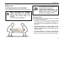
When transporting the centrifuge,
consider its weight (see "Technical
Data"); always grab it on both sides
ensuring that enough helpers are
around.
Do not lift on the front panel!
The centrifuge can be damaged by
jolting during the transport!
Transport the centrifuge only in the
upright position using proper containment and secure it properly.
Handle the centrifuge carefully.
Proper location
The centrifuge may only be used indoors. Its location
must meet the following criteria:
• A safety zone of at least 30 cm (12 inches) around
the centrifuge must be maintained. Hazardous materials must not be stored beside the centrifuge during its use.
• The laboratory bench or centrifuge trolley must be
stable and resonance-free. A good support is provided by a laboratory bench or a centrifuge cart with
lockable casters.
• To ensure sufficient air circulation, a minimum distance from the wall of 10 cm (4 inches) at the back
and of 15 cm (6 inches) on each side must be kept.
13
Before use
• The centrifuge must be protected from heat and
direct sunlight.
• The location must be well ventilated at all times.
UV rays reduce the durability of
plastics.
Protect the centrifuge, rotors and
plastic accessories from direct
sunlight.
Main connection
Connect the centrifuge only to a grounded main power
supply. Make sure that the power cord is compatible
with the valid safety regulations and that your main
voltage and frequency correspond to the specifications
on the instrument label.
Make sure that the centrifuge is switched off (on the
right-hand side of front panel) before connecting
electrical wire to main power supply.
RS232 interface
specifications
Main connection
14
Rotors and accessories
Rotors and accessories
A rotor is not included as part of a Multifuge® centrifuge.
A large variety of rotors are available as accessories.
In addition, there are adapters and reduction sleeves
for a variety of commercially available tubes and
bottles.
For a complete list of available tubes, bottles, adapters and accessories, please refer to our current sales
documentation.
For more information you can visit our web site at
http://www.Kendro.com
Multifuge® 1 S (air cooled)
During centrifugation, heat is generated by air friction
between the rapidly spinning rotor and the air inside
the rotor chamber. The continuous air flow in the air
cooled centrifuge is restricting the temperature rise of
the samples. The equilibrium temperature rise depends on the ambient temperature, the type of rotor,
the speed, the duration and the number of runs.
Use caution when touching rotors as
they may be hot after long runs at
high speed.
15
Rotors and accessories
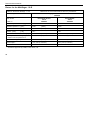
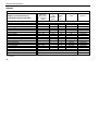
Rotors for the Multifuge® 1 S
Table 1: Rotors for Multifuge® 1 S
Differences of 120V instruments are shown in parentheses
Rotor designation
Swinging Bucket Rotor TTH 400
75002000
Rectangular bucket
150 ml
75002001
With bucket
Order no.
Round bucket
400 ml
75002002
Maximum permissible load [ g ]
4 x 540
Maximum speed nmax [ rpm ]
4700
( 4500 )
4700
Maximum RCF value at nmax
4618
( 4234 )
4618
Radius (max.)
18.7
[ cm ]
Acceleration / deceleration time [ s ]
4 x 570
18.7
40 / 35
( 50 / 40 )
40 / 35
12.0
( 14.0 )
13.0
( 55 / 40 )
Heating of samples at nmax [ °C ]
relative to room temperature 23°C,
run time 1 hour
Aerosol-tight *
Yes (with cap 75002003)
Yes (with cap 75002004)
Autoclavable
121°C
121°C
* Tested and approved by CAMR, Porton-Down, UK
16
Rotors and accessories
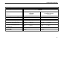
Table 1: Rotors for Multifuge® 1 S
Differences of 120V instruments are shown in parentheses
Rotor designation
Swinging Bucket Rotor TTH 400
75002000
Multiple carriers
14 x 15 ml
75002027
With bucket
Order no.
Multiple carriers
5 x 50 ml + 2 x 15 ml
75002028
Maximum permissible load [ g ]
4 x 420
Maximum speed nmax [ rpm ]
4700
( 4500 )
4700
( 4500 )
Maximum RCF value at nmax
4642
( 4256 )
4593
( 4210 )
Radius (max.)
18.8
[ cm ]
Acceleration / deceleration time [ s ]
4 x 430
18.6
40 / 35
( 65 / 40 )
40 / 35
( 65 / 40 )
15.0
( 13.0 )
15.0
( 13.0 )
Heating of samples at nmax [ °C ]
relative to room temperature 23°C,
run time 1 hour
Aerosol-tight
—
—
Autoclavable
121°C
121°C
17
Rotors and accessories
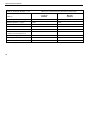
Table 1: Rotors for Multifuge® 1 S
Differences of 120V instruments are shown in parentheses
®
BIOshield 600 Rotor
4 x 150 ml
75002005
Rotor designation
Order no.
Micro plate carrier
MP 3300
75002010
Maximum permissible load [ g ]
4 x 540
2 x 600
Maximum speed nmax [ rpm ]
5700
4400
Maximum RCF value at nmax
6175
3355
Radius (max.)
17.0
15,5
[ cm ]
Acceleration / deceleration time [ s ]
55 / 55
( 80 / 50 )
35 / 35
( 40 / 35 )
Heating of samples at nmax [ °C ]
relative to room temperature 23°C,
Run time 1 hour
11.0
8.0
Aerosol-tight *
Yes
Yes (with cap 75002011)
Autoclavable
121°C
121°C
* Tested and approved by CAMR, Porton-Down, UK
18
Rotors and accessories
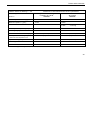
Table 1: Rotors for Multifuge® 1 S
Differences of 120V instruments are shown in parentheses
®
Micro Liter Rotor
48 x 2 ml
75003348
Fixed-Angle Rotor FA12.94 Highconic
6 x 94 ml / 12 x 16 ml
75002006
Rotor designation
Order no.
Maximum permissible load [ g ]
6 x 140 / 12 x 30
48 x 4
Maximum speed nmax [ rpm ]
10 150
15 000
Maximum RCF value at nmax
14 513
24 652
21 885
Radius (max. / min.)
12.5 / 6.1
9.8 / 5.9
45
45
Tube angle
[ cm ]
[°]
Acceleration / deceleration time [ s ]
40 / 50
Heating of samples
[ °C / at rpm / run time ]
9.0 °C / 10 150 / 1 h
15.0 °C / 12 000 / 1 h
15.0 °C / 15 000 / 15 min
23.0 °C / 15 000 / 1 h
Aerosol-tight *
Yes
Yes
Autoclavable
121°
138°
relative to room temperature 23°C
( 60 / 45 )
35 / 30
- outer ring
- inner ring
( 40 / 35 )
* Tested and approved by CAMR, Porton-Down, UK
19
Rotors and accessories
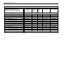
Rotors for the Multifuge® 1 S-R
Table 2: Rotors for Multifuge® 1 S-R
Differences of 120V instruments are shown in parentheses
Rotor designation
Swinging Bucket Rotor TTH 400
75002000
Rectangular bucket
150 ml
75002001
With bucket
Order no.
Round bucket
400 ml
75002002
Maximum permissible load [ g ]
4 x 540
Maximum speed nmax [ rpm ]
4700
( 4600 )
4700
Maximum RCF value at nmax
4618
( 4424 )
4618
Radius (max.)
18.7
[ cm ]
4 x 570
18.7
Acceleration / deceleration time [ s ]
35 / 35
( 45 / 40 )
35 / 35
( 45 / 40 )
Min temperature at nmax [ °C ]
10
( 12 )
4
(7)
4300
( 4100 )
4700
( 4450 )
relative to room temperature 23°C
Speed at 4°C
[ rpm ]
Aerosol-tight *
Yes (with cap 75002003)
Yes (with cap 75002004)
Autoclavable
121°C
121°C
* Tested and approved by CAMR, Porton-Down, UK
20
Rotors and accessories
Table 2: Rotors for Multifuge® 1 S-R
Differences of 120V instruments are shown in parentheses
Rotor designation
Swinging Bucket Rotor TTH 400
75002000
Multiple carriers
14 x 15 ml
75002027
With bucket
Order no.
Multiple carriers
5 x 50 ml + 2 x 15 ml
75002028
Maximum permissible load [ g ]
4 x 420
Maximum speed nmax [ rpm ]
4700
( 4500 )
4700
( 4500 )
Maximum RCF value at nmax
4642
( 4256 )
4593
( 4210 )
Radius (max.)
18.8
[ cm ]
Acceleration / deceleration time [ s ]
4 x 430
18.6
40 / 35
( 65 / 40 )
40 / 35
( 65 / 40 )
15.0
( 13.0 )
15.0
( 13.0 )
Heating of samples at nmax [ °C ]
relative to room temperature 23°C,
run time 1 hour
Aerosol-tight
—
—
Autoclavable
121°C
121°C
21
Rotors and accessories
Table 2: Rotors for Multifuge® 1 S-R
Differences of 120V instruments are shown in parentheses
®
BIOshield 600 Rotor
4 x 150 ml
75002005
Rotor designation
Order no.
Micro plate carrier
MP 3300
75002010
Maximum permissible load [ g ]
4 x 540
2 x 600
Maximum speed nmax [ rpm ]
6000
4400
Maximum RCF value at nmax
6842
3355
Radius (max.)
17,0
15,5
[ cm ]
Acceleration / deceleration time [ s ]
50 / 50
( 70 / 55 )
35 / 40
Min temperature at nmax [ °C ]
5
(8)
<0
5900
( 5700 )
4400
( 40 / 40 )
relative to room temperature 23°C
Speed at 4°C
[ rpm ]
Aerosol-tight *
Yes
Yes (with cap 75002011)
Autoclavable
121°C
121°C
* Tested and approved by CAMR, Porton-Down, UK
22
Rotors and accessories
Table 2: Rotors for Multifuge® 1 S-R
Differences of 120V instruments are shown in parentheses
®
Micro Liter Rotor
48 x 2.0 ml
75003348
Fixed-Angle Rotor FA12.94 Highconic
6 x 94 ml / 12 x 16 ml
75002006
Rotor designation
Order no.
Maximum permissible load [ g ]
6 x 140 / 12 x 30
48 x 4
Maximum speed nmax [ rpm ]
10 350
15 000
Maximum RCF value at nmax
15 090
24 652
21 885
Radius (max./min.)
12.5 / 6.1
9.8 / 5.9
45
45
Tube angle
[ cm ]
[°]
- outer ring
- inner ring
Acceleration / deceleration time [ s ]
45 / 45
( 55 / 50 )
30 / 30
( 40 / 30 )
Min temperature at nmax [ °C ]
0
(4)
4
(6)
10 350
15 000
( 14 500 )
Aerosol-tight *
Yes
Yes
Autoclavable
121°C
138°C
relative to room temperature 23°C
Speed at 4°C
[ rpm ]
* Tested and approved by CAMR, Porton-Down, UK
23
Rotors and accessories
Adapter
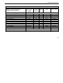
Table 3: Adapter (1)
Adapter and accessories for
rectangular buckets 7500 2001
Centri-Lab® Adapter type A plus
14 x 7 ml blood sampling
12 x 15 ml blood sampling
8 x 15 ml conical
Centri-Lab® Adapter type A
40 x 1.5 / 2 ml micro liter tube
20 x 7 ml DIN
12 x 15 ml DIN
4 x 25 ml universal container
5 x 25 ml DIN
2 x 50 ml DIN
2 x 50 ml conical
1 x 50 ml oil test
1 x 100 ml DIN
1 x 150 ml DIN
for cyto-system
1)
* Max. tube length with aerosol-tight cap
Max. tube
dimensions
d1) x length/ *
[mm]
Cap
diameter
[ mm ]
Tubes
per
rotor
Color
Order no.
13.0 x 117
17.0 x 117
17.0 x 120
16.5
19.5
22.0
56
48
32
grey
white
brown
7500 2022
7500 2021
7500 2020
11.0
13.0
17.0
22.5
25.0
34.0
29.5
13.0
18.3
31.0
25.9
35.6
37.5
48.1
-
160
80
48
16
20
8
8
4
4
4
-
black
yellow
red
green
orange
green
green-yellow
nature
blue
grey-blue
-
7500 5335
7500 5321
7500 5322
7500 5391
7500 5323
7500 5324
7500 5386
7500 5339
7500 5325
7500 5326
7600 3417
x 45
x 115
x 115
x 100
x 115
x 120
x 120
44.0 x 120
50.0 x 110
-
Aerosol-tight caps
2 pieces, incl. seals and lubricants
7500 2003
Spar seal
4 pieces, incl. lubricants
7500 2008
d = diameter
24
Rotors and accessories
Table 3: Adapter (2)
Adapter and accessories for
round buckets 7500 2002
1)
* Max. tube length with aerosol-tight cap
Max. tube
dimensions
d1) x length / *
[mm]
Cap
diameter
[mm]
Tubes
per
rotor
Centri-Lab® Adapter type E
34 x 1.5 / 2 ml micro liter tube
18 x 7 ml DIN
10 x 7 ml blood sampling
10 x 15 ml DIN
8 x 15 ml conical
5 x 25 ml US-urine
5 x 25 ml DIN
3 x 50 ml universal container
3 x 50 ml conical
3 x 50 ml DIN
1 x 100 ml DIN
1 x 250 ml bottle
400 ml bottle
Aerosol-tight caps
10.5 x 46
14.0
136
13.0 x 123
14.0
72
13.0 x 123
18.4
40
17.2 x 122
18.4
40
17.0 x 127
23.0
32
16.5 x 123
27.5
20
25.5 x 121
29.0
20
25.0 x 120
32.0
12
29.0 x 119
37.5
12
34.5 x 120
36.0
12
45.0 x 134
59.0
4
4
62.0 x 135
80.0 x 135
4
2 pieces, incl. seals and lubricants
Spar seal
4 pieces, incl. lubricants
Color
No. of order
black
yellow
grey
red
brown
orange-red
orange
green-yellow
green-yellow
green
blue
nature
nature
7500 7578
7500 7571
7500 7579
7500 7572
7500 7621
7500 7581
7500 7573
7500 7580
7500 7577
7500 7574
7500 7575
7500 7622
7500 7583
7500 2004
7500 2009
d = diameter
25
Rotors and accessories
Table 3: Adapter (3)
Adapter and accessories for
BIOshield® 600 Rotor 7500 2005
Centri-Lab® Adapter type A
40 x 1.5 / 2 ml micro liter tube
20 x 7 ml DIN
12 x 7 ml blood sampling
11 x 15 ml blood sampling
6 x 15 ml conical
12 x 15 ml DIN
4 x 25 ml universal container
5 x 25 ml DIN
2 x 50 ml DIN
2 x 50 ml conical
1 x 50 ml oil test
1 x 100 ml DIN
1 x 150 ml DIN
for cyto-system
Spar seal
1)
26
d = diameter
* max. tube length with aerosol-tight cap
Max. tube
dimensions
d1) x length / *
[mm]
Cap
diameter
[ mm ]
11.0
13.0
13.0
17.0
17.0
17.0
22.5
25.0
34.0
29.5
x 45
x 115
x 117
x 117
x 120
x 115
x 100
x 115
x 120
x 120
44.0 x 120
50.0 x 110
-
1 set, incl. lubricants
13.0
16.5
19.5
22.0
18.3
31.0
25.9
35.6
37.5
48.1
-
Tubes
per
rotor
160
80
48
44
24
48
16
20
8
8
4
4
4
-
Color
No. of order
black
yellow
grey
white
brown
red
green
orange
green
green-yellow
nature
blue
black
-
7500 5335
7500 5321
7500 5330
7500 5327
7500 5387
7500 5322
7500 5391
7500 5323
7500 5324
7500 5386
7500 5339
7500 5325
7500 5326
7600 3417
7500 2007
Rotors and accessories
Table 3: Adapter (4)
Adapter and accessories for
Fixed-Angle Rotor FA12.94
7500 2006
Max. tube
dimensions
d1) x length
[mm]
Adapter for 94 ml cavity
1.5 ml micro tube
3.5 ml
6.5 ml
12 ml
16 ml *
38 ml
50 ml
15 ml conical
50 ml conical
11 x 58
11 x 103
13 x 115
16 x 96
18 x 124
25 x 112
29 x 118
16.5 x 120
30 x 117
Number per
adapter
4
4
2
2
1
1
1
1
1
Number
per
rotor
Color
No. of
order
24
24
12
12
6
6
6
6
6
nature
nature
nature
nature
nature
nature
blue
nature
green
7600 2905
7500 3091
7500 3092
7500 3093
7600 2906
7500 3094
7500 3102
7500 3095
7500 3103
Spare seal
2 sets, incl. lubricants
7500 3058
Adapter for 16 ml cavity
for 10 ml Vacutainer
for 7 ml Vacutainer *
for 5 ml Vacutainer
Reducer insert (16 x 100 mm)
Reducer insert (13 x 100 mm)
Reducer insert (13 x 75 mm)
7500 3763
7600 3225
7600 3226
1)
d = diameter
* For 7 ml Vacutainer, Adapter 7600 2906 and 7600 3225 required.
27
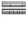
Rotors and accessories
Tabelle 3: Adapter (5)
Accessories for
Micro plate carrier MP 3300
7500 2010
No. of
order
Aerosol-tight cap
Adapter for micro plate carrier
Spare seal
7500 2011
7500 2013
7500 2012
2 pieces, incl. seals and lubricants
2 pieces, incl. lubricants
Table 3: Adapter (6)
Adapter for
Micro Liter Rotor 7500 3348
Max. tube
dimensions
d1) x length
[ mm ]
Tube capacity
[ ml ]
Reduction sleeve PCR
Reduction sleeve
Reduction sleeve
6.2 x 20
8 x 43.5
6 x 46
0,2
0.5 / 0,6
0.25 / 0.4
1)
28
d = diameter
Number
per set
24
24
24
Color
No. of
order
Grey
Turquoise
Red
7600 3750
7600 3758
7600 3759
Rotors and accessories
Handling the rotor
Swinging Bucket Rotor TTH 400
BIOshield® 600 Rotor
Micro plate carrier
All positions must always be loaded
with identical carrier buckets!
The various swinging buckets are split up into weight
categories. These can be identified through the letters
suffixing the order number on the bucket. Buckets of
identical weight categories should always be installed
in opposing rotor positions to avoid imbalance.
In case of repeat orders of buckets
and carriers, please indicate the
present weight category.
The swinging bucket rotors have a slide coating which
guarantees perfect operation without additional lubrication of body trunnion pins for many years.
Should an imbalanced run occur although
the weight is correct, this could be due to
wear of the slide coating.
In this case the rotor function remains intact
through normal lubrication:
at regular intervals, apply a light coating of
lubricant to the rotor body trunnion pins and
to the corresponding mating surfaces of the
buckets!
Lubricant 7000 6692 is supplied with the
centrifuge.
29
Rotors and accessories
BIOshield® 600 Rotor
7500 2005
Do not run the rotor without the rotor
cover installed.
Store the BIOshield® Rotor with the cover removed
after cleaning. This will enable the rotor to dry
thoroughly.
30
Always maintain the rotor in the recommended manner.
The rotor and accessories must be cleaned
and inspected regularly: do not use when
showing signs of corrosion or cracking.
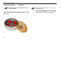
Rotors and accessories
Micro plate carrier MP 3300
7500 2010
Remove the appropriate plate holder from
the carrier body for loading and unloading of
micro plates in the Micro plate carrier.
The operation is permissible only
with the associated carriers!
(Label "75002010")
Some commercially available microplates are not rated for the maximum
achievable RCF of the Microplate carrier. Therefore please pay attention to
the specifications of the plate manufacturer.
Before loading, ensure that the rubber bottom is placed
in the cut-outs of the bottom of the plate holder.
The maximum loading height amounts to 55 mm!
Make sure the rotor is balanced!
31
Rotors and accessories
Aerosol-tight operation
Aerosol-tight rotors and tubes are only
to be opened in an approved safety
work bench when centrifuging dangerous samples!
It is necessary to pay attention to the
maximum permissible filling quantities!
Correct operation when filling the sample tubes and
closing the rotor cover are prerequisites for aerosol biocontainment.
Before use, the seals in the rotors and
rotor covers as well as the aerosol-tight
caps have to be checked for abrasion
or damage and have to be slightly
greased.
Replace damaged O-rings and seals!
32
Use the special lubricant
7600 3500 only to grease the seals!
Spare parts are delivered with the rotor or may be ordered separately.
Replace damaged or clouded caps
and lids of rotors and tubes
immediately.
The tubes are only to be filled in such a way that the
sample does not reach the rim of the tube during centrifuging.
Rotors and accessories
Closing the rectangular bucket 75002001
aerosol-tightly
After putting on the cap both levers are pressed down
until they noticeably click in.
Closing the Micro test plates rotor MP3300
75002010
aerosol-tightly
Please flap both lock levers upward. The cap can now
be easily put on the bucket. The bucket is locked
through flapping down the levers.
Both of the levers must click in order to
achieve aerosol-tight bio-containment!
Both of the levers must click in order to
achieve aerosol-tight bio-containment!
Levers not being flapped down
may cause damage to the caps
during centrifugation!
33
Rotors and accessories
Closing the round bucket 75002002
aerosol-tightly
After greasing the seal, turn the lid until it sits lightly on
the bucket.
To achieve uniform seal, turn the lid tighter by 1 grip
area (approx. 10°). Use the setting marks on the
bucket as a guide.
Grip area
Bucket mark
34
Closing Fixed-Angle Rotor aerosol-tightly
The hexagon wrench should be used as a support tool
to fasten and loosen the lid of the fixed angle rotor in
order to achieve secure closing (insert the hexagon
wrench through the hole in the screw cap).
Please pay attention to the maximum
permissible filling volume during centrifugation of dangerous samples!
Rotors and accessories
Rotor
Vessel type /
maximum filling volume
Micro Liter Rotor 48 x 2.0 ml
75003348
Micro 1,5 ml
Micro 2,0 ml
1,0 ml
1,5 ml
Fixed-Angle Rotor FA12.94
75002006
Falcon 50 ml
Falcon 15 ml
49 ml
14 ml
others:
- 2/3 nominal volume
•
Micro
–
micro centrifuge tube
•
Falcon
–
tube type Falcon
35
Rotors and accessories
Checking of aerosol-tight bio-containment
The checking of the rotor type and bucket was done
according to the dynamic microbiological test procedure with regard to EN 61010-2-020 appendix AA.
The aerosol-tight bio-containment of the rotor mainly
depends on proper handling!
Check the aerosol-tight bio-containment
of your rotor whenever necessary!
It is very important that all the seals and
seal-surfaces are carefully inspected for
wear and damages like cracks, scratches
and embrittlements!
For a quick test one can check the aerosol-tight buckets and fixed angle rotors according to the following
procedure:
•
Slightly grease all seals.
•
Fill the bucket or rotor with approx. 50 ml carbon
dioxide mineral water.
•
Close the bucket or rotor according to the respective handling instructions.
36
•
Shaking the bucket releases the carbon dioxide of
the water, and an excessive pressure is built up.
•
Leaks are recognized by humidity release and
audible disinflation of gas mix.
•
Finally buckets respectively rotor, lid and lid seal
have to be dried.
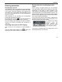
Operation
Operation
Switching on the centrifuge
Locate the main power switch on the right-hand side of
the front panel, and set it to the ON (I) position. For a
couple of seconds the following reading appears in the
control panel:
The display shows that the instrument is going through
an internal check of its software.
(See table on page 70).
After this check, the display shows the actual value
mode. The remaining run time and speed should both
read 0. The display of the acceleration/deceleration
curve depends on the last set value.
The following figure gives an example of possible readings. A detailed description of possible settings is given
below in this chapter.
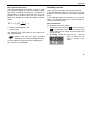
Actuating the lid
Opening the lid
Press the "open lid" key .
If the message "Lift lid” appears, slightly lift the lid.
(Emergency release in case of malfunction or power
failure: see chapter "Troubleshooting")
Closing the lid
The centrifuge lid is locked by slightly pressing down
the front part of the lid. Locking is motor-driven.
Do not slam the lid!
37
Operation
Installing the rotor
Improper or improperly combined
accessories may cause severe damage to the centrifuge!
The rotors approved for the Multifuge® are detailed in
the chapter "Rotors and accessories". Use only rotors
listed for this instrument.
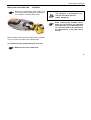
To install the rotor, you will need the wrench (see chapter "Parts supplied” – page 8).
Proceed as follows:
1. Open the lid and make sure that the rotor chamber
is clean. Clean any dust, foreign material or sample
residues out of the chamber before use.
2. Check if the collet chuck is loose (collet chuck
moves freely on the spindle). If not, loosen the rotor
seat using the supplied socket wrench.
3. Place the rotor on top of the collet chuck so that the
rotor is located precisely above the center.
38
4. The rotor must glide freely down the collet chuck
until it hits the lower stop.
5. If you have positioned the rotor correctly, you can
tighten the collet chuck easily using the supplied
hex wrench.
6. Place the rotor cover on applicable rotors and
tighten it securely.
Regularly check the proper positioning
of the rotor and re-tighten the collet
chuck as needed.
Please take care of the legibility of the inscription of the
installed swinging bucket rotor cross.
(Rotor identification must point to the chamber bottom)
For the swinging bucket rotor, the set bucket type must
be permitted for the operation in the respective rotor.
Please note the requirements of chapter "Bucket selection of swinging bucket rotors"
Operation
Loading the rotor
Maximum loading
Overloading can result in destruction
and severe damage to the centrifuge.
If you wish to centrifuge samples that, together with the
adapters, exceed the maximum permissible load, you
must either reduce the sample volume or calculate the
permissible speed nperm according to the following formula:
n
perm
=n
max
∗
maximum permissible load
actual load
®
The Multifuge can reach high rotational speeds exerting enormous centrifugal force. The rotors are designed to warrant sufficient residual strength even at
the highest permissible speed.
However, this safety system presupposes that the
maximum permissible load of the rotor is not exceeded.
* nperm
nmax
= permissible speed
= maximum speed
Please get acquainted with the data
about the maximum permissible loads
and maximum speeds in chapter "Rotor and accessories".
39
Operation
Filling the centrifuge tubes
Check carefully whether your tubes
are approved for the respective RCF
value. Follow tube manufacturer’s
recommendation.
For common borosilicate glass tubes the maximum
permissible rcf is limited to 4000 xg!
The tube manufacturers normally limit the respective
maximum allowed RCF value to the fixed angle rotor.
Please note that for the same RCF value
the stress for the tubes in a swingingbucket rotor is higher!
Because of the higher difference of the radii (rmax - rmin)
the pressure of liquid column to the tube bottom is
appreciably higher and strongly depended on filling.
Plastic tubes and bottles – especially for the highest
load (speed, temperature) – have a limited life time and
must be replaced as recommended by the manufacturer.
40
Maximum permissible load difference
The smaller the imbalance of the centrifuge,
the better the separation effect, because as
imbalance is minimized, so is the resulting
vibration, which could affect separation
quality.
Therefore it is important that the tubes are properly
balanced.
In case of exceeding the rotor specific imbalance values, the electronic imbalance shut-down is activated.
Operation
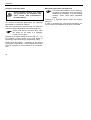
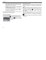
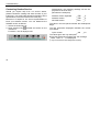
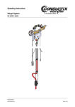
Inserting the centrifuge tubes
Fixed-angle rotors:
The rotor must be loaded symmetrically. Failure to do so can cause rotor
imbalance, which may lead to noisy
operation, affect separation quality, or
result in imbalance detection shutdown, as well as introduce significant
detrimental wear to the motor and
drive system.
When only partially loading the rotor, ensure that opposite bores receive tubes of equal weight (when centrifuging a single sample, place a centrifuge tube filled
with water opposite of the sample).
After placing the tubes, install the rotor cover.
Proper loading
Improper loading
41
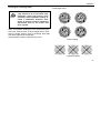
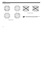
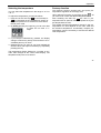
Operation
Swinging bucket rotors:
Improper loading
These examples are to be applied to the
other rotors in an analogous manner!
Proper loading
42
Operation
Entering parameters
Deceleration curves
The Multifuge® offers 9 acceleration and deceleration
profiles for optimal centrifuging of samples and gradients. Please consult the diagrams in the Appendix for
more detail of the acceleration and deceleration curves
(for rotors not mentioned here you may extrapolate the
respective values).
After switching on the centrifuge, the centrifugation
profiles last entered are selected.
By pressing the "set" key
you can scroll through the
profile settings until the desired profile is reached.
Once the display stops flashing, the value is stored in
memory and remains unchanged until changed by a
new entry.
Switching from speed to RCF display
Upon turning on the centrifuge, the speed display is
set.
Use the speed mode selection key
to switch the
speed entry and display between rpm and RCF.
Bucket selection for swinging bucket
rotors
When running a swinging bucket rotor, the automatic
rotor identification feature will recognize the rotor body.
Depending on the bucket or carrier installed on the
rotor body the corresponding type of bucket or carrier
must be selected on the bucket selection function. The
bucket selection affects the correct RCF values display
and the correct selection of the corresponding parameters of the temperature regulation.
The current part number of the buckets is displayed by
pressing the bucket selection key (corresponds to the
last four 4 digits of the order number).
To change the bucket
selection, press the
bucket selection key
again until the correct
set of buckets appears.
The value is accepted when the change back to the
speed RCF display has occurred.
43
Operation
Selecting speed
The centrifuge speed can be set to a minimum of 300
rpm and to a maximum of 15 000 rpm (depending on
the rotor).
You can adjust the speed in 10 rpm increments. Proceed as follows:
1. By pressing the "set" keys
once (for an increase)
or
(for a decrease) in the "speed" section of the
control panel, you switch from actual to set point
values. The value last stored is displayed, with the
digit entered flashing (if there is no value stored in
memory, this is indicated by dashes -----).
2. By briefly pressing the input key you can raise or
lower the speed by
one step (10 rpm)
at a time.
3. If you hold down the pressed key, the display
changes slowly at first and at an accelerated pace
after a few seconds.
4. Release the key as soon as you have reached the
desired value, and adjust if necessary by repeatedly
pressing the key. The decimal place flashes for a
44
number of seconds, then changes to a permanent
display. The speed is now stored.
For faster operation, you may shift the flashing cursor in the speed/RCF and the run
time panels: just press both
and
simultaneously. The cursor moves by one
digit to the left for each time the key is
pressed.
Entering the RCF value
You can adjust the RCF set point in steps of 1. The set
point is entered analogously to the speed.
As long as the rotor has not been identified, it is not
possible to display RCF values. This is signaled by
dashes ----- in the display.
Shortly after starting the centrifuge run, the rotor is
identified and the current value is displayed.
NOTE:
If you set an extremely low RCF value, this may be
automatically corrected if the resulting speed would be
lower than 300 rpm.
Operation
More about the RCF value
The relative centrifugal force (RCF) is given in multiples of the earth gravity g. It is a dimensionless number
that allows comparing the efficiency of separation or
sedimentation of diverse instruments since it is independent of the instrument used. The only values entered in the equation are radius and speed of centrifugation:
2
n
RCF = 11,18∗
∗r
1000
r = radius of centrifugation in cm
n = speed in rpm
The maximum RCF value refers to the maximum radius of the tube bore.
Please note that this value decreases
depending on the tubes and adapters used.
You may take this into account when calculating the
RCF value for your application.
Selecting run time
There are two time modes: standard and extended.
In the standard time mode you can select a run time
between 1 min and 9 h 59 min or continuous operation
(hLd) .
In the extended mode you can select a run time between 1 min and 99 h (from 10 h in one-hour steps), or
continuous operation (hLd).
Run time selection
To set a time, proceed as follows:
1. Press one of the "set" keys
(for an increase) or
(for a decrease) in the "run time" section of the
control panel once to switch from the actual to the
set point mode.
2. By briefly pressing the "set” key you can now
raise or lower the run
time in 1-minute increments.
45
Operation
3
4
If you keep the selected key pressed, the display changes slowly at first and at an accelerated pace after a few seconds.
Release the key as soon as you have reached
the desired value, and adjust if necessary by
repeatedly pressing the key.
The minute display flashes for a number of
seconds, then changes to permanent display.
The run time is now stored.
You may shift the flashing cursor to set the value as
described under "Selecting speed".
Continuous operation
To switch the Multifuge® to the continuous mode, you
until the display reads "hLd") .
must press the key
With this
setting, the centrifuge keeps running until stopped
manually.
46
Extended time mode
You have the option of switching to the extended time
mode. To switch it on or off press the program selection key
and simultaneously start the centrifuge. As long as
you keep the key pressed the selective mode is active.
Pressing the upward key , you can switch back and
forth between the signal menu "beep" and the time
menu "t-set".
After selecting the time menu "t-set”, you can switch
between the standards time mode "00.0" and the extended time mode "00”.h by pressing the upward key
.
The time input in excess of 10 hours is set in one hour
increments.
Operation
Selecting the temperature
You can select the temperature in the range of -9 °C to
+40 °C.
To adjust the temperature, proceed as follows:
(for an increase) or
1. Press one of the "set" keys
(for a decrease) in the "temperature" section of
the control panel once to switch from the actual to
the set point mode.
2. By briefly pressing the input key you can now raise
or lower the run time in 1°
steps.
Pretemp function
The Pretemp function permits easy and quick pretemperature-regulation of the empty rotor.
Upon calling this function by pressing the key
you have to do is enter the desired temperature.
, all
After actuating the start key
, the rotor is pretempered with an optimum rotational speed set by the
pre-temperature-function.
The actually achieved temperature change in the pretemperature run time depends on the rotor used and
the ambient temperature. Occasionally multiple pretemperature runs are necessary to achieve the desired
rotor temperature.
3. If you keep the selected key pressed, the display
changes continuously slowly at first and then at accelerated paces up or down.
4. Release the key as soon as you have reached the
desired value, and adjust if necessary by repeatedly
pressing the key.
The temperature display flashes for a number of seconds, then changes to the current value display. The
temperature set point is now stored.
47
Operation
Starting the centrifuge
Imbalance display
Once the rotor is properly installed, the main switch is
turned on and the lid is closed, you can start the centrifuge.
If rotor imbalance is detected, shortly after the rotor
reaches 300 rpm, the message "bAL" will appear in the
speed display.
The run is terminated,
and you may restart the
centrifuge after correcting the imbalance (check
loading).
Press the "start" key
in the control panel. The centrifuge accelerates to the selected value. Simultaneously,
the time display starts counting down from the selected
set time, giving the remaining run time in minutes (during continuous operation the time display goes forward).
If a value exceeding the maximum permissible speed
or RCF of the respective rotor was entered, this is indicated after the start of the centrifuge by the alternately
flashing messages "rotor" and the maximum permissible value for the inserted rotor.
Within 15 seconds you may adopt this value by again
pressing the "start" key; the centrifugation is then continued. Otherwise the centrifuge stops, and you must
enter a permissible value.
You cannot open the lid during the run.
48
Changing the settings during the run
You can change all settings during a run. By pressing
any one of the "set" keys in the control panel once, you
can switch from the actual to the set point mode.
The to-be-adjusted setting flashes and can then be
altered. Once the data input is finished and the display
has changed to the actual value display mode, the new
settings become operative.
Operation
Stopping the centrifuge
Temperature control during standby
Stopping with preset run time
Normally the run time has been selected, and all you
have to do is to wait until the centrifuge terminates the
run automatically at the end of the set time.
As soon as the speed reaches zero, the display reads
"end". You can now open the centrifuge by pressing
the "open lid" key
and remove your samples.
If the lid has not been fully lifted out of the lid lock, the
message "lift lid" appears (you must manually lift the
lid).
You can manually stop the centrifuge at any time by
pressing the "stop" key .
At this point the remaining run time is displayed.
Temperature control becomes active once the rotor
has been identified. This is the case after a centrifugation run exceeding 300 rpm. At standby the display
reads "end".
If the rotor has not been identified (lid has been closed
and the "start" key
has not yet been pressed,
speed panel shows "0" with flashing point), the instrument regulates the temperature so that the samples
cannot freeze in any one of the usable rotors.
If you find the systematic deviation in temperature of up
to 4 K unacceptable, you have to start the centrifuge
for a short period of time until the rotor is identified.
Stopping with continuous operation
If you have chosen continuous operation, you must
stop the centrifuge manually. Press the "stop" key
in
the control panel. The centrifuge starts deceleration
with the preset deceleration profile.
The display reads "end", and you can open the lid by
pressing the "open lid" key
and remove your samples.
49
Operation
Working with programs
The 4 program selection keys offer the option of storing
and recalling the individual centrifugation processes.
Program display
By actuating one of the program selection keys, the
specific set point values stored are displayed.
Entering/changing a program
All program places have been factory-set at the same
values.
To change these values, proceed as follows:
− Enter the desired parameters
→ Only the selection panel affected by the changes is flashing.
− After entering all set point values, press the desired
program selection key for approx. 3 Seconds:
→ The entering is confirmed by the signal, the new program is
stored.
Repeat the process to set values to additional program
places.
50
Centrifuging with a program
After closing the centrifuge lid, call the desired program
memory number using the program selection key and
press the start key .
If the rotor is started with a program the speed or RCF
set point value which exceeds the permissible value of
the inserted rotor, or the RCF/set point which is below
the rotor-specific minimum, the program selection keys
LED of the program chosen beforehand will be
switched off after the rotor identification.
Operation
”Quick Run”
Removing the rotor
®
For short-time operation, the Multifuge is equipped
with a "quick run" function.
Short-time centrifugation is started by pressing the
"quick run" key
continuously; it stops as soon as the
key is released.
In this mode the centrifuge accelerates with full power
up to the maximum speed. The set speed or RCF is
ignored in this case.
Depending on the rotor, the centrifuge
accelerates to the maximum speed!
Check carefully whether you have to
maintain a specific speed for your
application.
During acceleration the time is counted forward in seconds. The display remains until the centrifuge lid is
opened.
1. Open the centrifuge lid.
2. Remove the rotor cover (on applicable rotors).
3. Unscrew the clamping sleeve counterclockwise
using the socket wrench supplied with the instrument until no resistance exists.
4. Grab the rotor with both hands and carefully pull it
perpendicularly off the drive shaft. Make sure not to
tilt it.
Grab rotor with both hands and pull
upwards perpendicularly.
When using an aerosol-tight bio-containment cover,
you may remove the respective rotor from the drive
shaft without opening the cover! You may then open
the rotor e.g. in a safety work bench and decontaminate it.
51
Operation
Audible alarm
Turning off the centrifuge
Accompanying all error messages, a warning signal is
given out which can be silenced upon pressing any
key.
You have the option of signaling the end of a run
acoustically. To activate or deactivate this option, press
the program key
and simultaneously switch on
the centrifuge. As long as you keep this key pressed,
the selection mode is active.
The speed panel shows "beep", and the time panel
shows "on" or "off".
By actuating the upward-key
in the time panel the
signal function can be switched on or off.
The centrifuge is turned off by switching the main
switch into the "0"position.
The main power switch should be turned off
after a complete centrifugation run. Without
motor deceleration, it takes much longer
until the rotor comes to a halt.
When the message "rotor" flashes, pressing
the start key once is sufficient to turn off the
warning signal and to accelerate the rotor to
the maximum speed displayed by the instrument.
52
The centrifuge lid can only be opened automatically if
the centrifuge is turned on!
Maintenance and care
Maintenance and care
Maintenance to be performed by the
customer
For the protection of persons, environment and material you are obliged to clean the centrifuge regularly
and to disinfect it if necessary.
Unsuitable cleaning agents or disinfection procedures may damage the
centrifuge and its accessories!
If you intend to use cleaning agents
or disinfection procedures not recommended by the manufacturer, you
have to ensure that the foreseen procedure does not cause any damages
to the instrument by consulting the
manufacturer!
Cleaning
Pull mains plug before cleaning the
instrument!
Clean the case, the rotor chamber, the rotor and the
accessories regularly, and in case of need. This is
indicated both for reasons of hygiene and to prevent
corrosion due to contamination sticking to the instrument and its accessories.
Clean them with mild agents of pH values ranging from
6 to 8.
For other cleaning agents please consult KENDRO
Services!
Immediately after cleaning, dry the aluminum parts or
put them into a warm-air dryer at a temperature not
exceeding 50°C.
53
Maintenance and care
During cleaning, liquids and especially organic solvents should not
come into contact with the drive
shaft and the ball bearing.
Organic solvents may decompose
the lubricant of the motor bearing.
The drive shaft may seize.
Instruments with refrigeration unit:
If a strong ice sheet is present in the internal
chamber, be sure to remove all condensation after defrosting!
Please clean the venting slots regularly!
Before cleaning the venting slots,
please disconnect the centrifuge
from the mains supply.
Please pull mains plug!
54
Disinfection
If a centrifuge tube containing infectious material leaks
during a run, you have to disinfect the centrifuge immediately.
Infectious material could enter the
centrifuge if spills or tube breakage
occur.
Danger of infection may occur upon
contact! Take appropriate protective
measures for personnel!
Pay attention to the permissible filling
volumes and loading limits for the
tubes!
In case of contamination the operator
has to ensure that no other persons
are at risk!
Contaminated parts will have to be
decontaminated immediately.
If required, further protective measures have to be initiated.
Maintenance and care
Rotor and rotor chamber must be treated with a neutral, universal disinfectant. Best suited for this purpose
are disinfectant sprays, ensuring that all rotor and accessory surfaces are covered evenly.
• Please use 70% ethanol for disinfection.
Please pay attention to the safety
measures and handling requirements
when applying these substances!
For other disinfectants please consult KENDRO
Services!
• You may disinfect the rotor and the accessories as
described in the following section. Be sure to follow
the pertinent safety procedures for handling infectious material.
1. Pull mains plug.
2. Unscrew the rotor chuck.
3. Grab the rotor with both hands and pull it perpendicularly off the drive shaft.
4. Remove the centrifuge tubes and adapters, and
disinfect them or dispose of them as necessary.
5. Treat the rotor and the rotor lid according to the
instructions given for the disinfectant (soaking in
liquid or spraying). You must strictly observe the
specified action times!
6. Turn the rotor head down and drain off the disinfectant. Afterwards thoroughly rinse rotor and lid with
water.
7. Dispose of the disinfectant according to valid regulations.
8. Aluminum rotors have to be treated with anticorrosive protective oil subsequently.
Disinfection with bleaching lye
These agents contain highly aggressive hypochlorites and must not be
used with aluminum rotors!
55
Maintenance and care
Decontamination
For general radioactive decontamination, use a solution of equal parts of 70% ethanol, 10% SDS and water. Follow this with ethanol rinses, then de-ionized
water rinses, and dry with a soft absorbent cloth. Dispose of all washing solutions in appropriate radioactive
waste containers!
Autoclaving
Check whether autoclaving is permitted!
You may autoclave the rotor and the adapters at
121 °C.
Maximum permissible autoclaving cycle: 20 min at
121 °C.
The rotor must be cleaned and rinsed with distilled
water before being autoclaved. Remove the rotor lid,
the centrifuge tubes and the adapters. Place plastic
rotors on an even surface to avoid deformation.
56
Chemical additives to the steam are not
permitted.
Never exceed the maximum permissible values for autoclaving temperature and autoclaving time.
Should the rotor show signs of wear,
you must stop using it!
Corrosion protective oil 7000 9824 is delivered with the
centrifuge.
Maintenance and care
The KENDRO service offer
Warranty conditions
Kendro Laboratory Products recommends annual servicing of the centrifuge and the accessories by authorized customer service or trained professionals. The
customer service personnel inspect:
The warranty period starts on the day of delivery.
Within the warranty period the centrifuge is repaired or
replaced free of charge if there are provable faults in
materials or workmanship.
Conditions for a warranty are:
• the electrical installations
• the suitability of the location
• the lid lock mechanism and the safety circuit
• the rotor
• the rotor fastening and the drive shaft
Defective material is exchanged.
KENDRO offers inspection and service contracts covering it. Inspection costs are charged as flat-rate contracts.
• the centrifuge is used according to the instructions
of use
• mounting, extensions, settings, alterations or repairs are carried out exclusively by personnel authorized by KENDRO
• the required maintenance and care procedures are
carried out regularly.
Necessary repairs are carried out free of charge within
the warranty conditions, and requires payment after
expiration of the warranty period.
57
Maintenance and care
Notes
58
Troubleshooting
Troubleshooting
Emergency lid release
In case of a power failure the lid cannot be opened
normally using the electrical lid unlocking mechanism.
To permit unloading in this case, the centrifuge is
equipped with an emergency override release. However, you may only use this system in case of emergency.
Rotors can spin at high speed! Touching them may cause severe injuries!
Always wait for several minutes until
the rotor has come to a complete stop.
In case of a power outage, the brake
does not function, and deceleration
takes much longer than normal!
Proceed as follows:
1. Make sure that the rotor is at a complete stop
(observe through window in the cover).
During a power outage, it is impossible
to lock the lid once the emergency lid
release has been used. Never stop the
rotor using your hands or using tools!
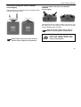
2. Unplug the main power cord.
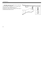
3. Facing the centrifuge under the left-hand side, there
is a plastic plug that can be removed using a
screwdriver. After removal, use your fingers or a
pair of pliers to pull the attached cord and activate
the manual door override. The lid will open and you
can remove your samples.
Emergency release
59
Troubleshooting
4. Afterwards, push the cord back into the instrument
and reinsert the plastic plug.
Once the power is restored, you can connect the instrument to the main supply and turn it on.
Following the self test of the centrifuge, the lid may be
closed and locked with the motor.
60
Troubleshooting
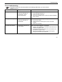
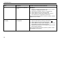
Error troubleshooting
If problems other than those described in the following tables arise, you must contact
KENDRO service.
Error
Displays remain dark
Displays fail briefly.
Lid cannot be opened.
Symptom
Possible causes and corrective measures
The drive stops.
Mains voltage disconnection
The rotor stops without
deceleration. The lid
cannot be opened.
1. Is the mains plug turned on?
2. Check the main connection.
3. If the main connection is ok, contact the nearest KENDRO
service station.
The drive stops suddenly.
Main connection was briefly interrupted
The rotor stops without
deceleration.
1. Turn off main switch.
2. Check whether the mains power cord is connected
properly.
3. Restart the centrifuge.
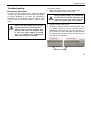
Pressing the "open lid" key
has no effect.
Lid not correctly engaged or lid warped.
1. Check if main connection is working and the instrument is
switched on (display is lit).
2. Press the lid down in the middle of the front section once,
and press the "open lid" key.
3. If this is unsuccessful, you may open the lid using the
emergency lid release (see page 59).
61
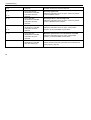
Troubleshooting
Error
Symptom
Possible causes and corrective measures
–
Centrifuge is exceptionally
noisy.
Imbalance.
1. Stop the centrifuge by pressing the "stop" key, in case of
emergency, unplug mains power cord.
2. Wait until the centrifuge comes to a complete stop.
3. Check whether the rotor is properly loaded.
4. Check whether a broken tube, damage to the rotor or
motor malfunction is responsible for the noise.
If you cannot locate and solve the problem yourself, contact a
KENDRO service station.
Message "bAl" appears
in display.
Rotor stops with
deceleration.
Imbalance switch actuated
1. Open the instrument by pressing "open lid" key ..
2. Check whether the rotor is properly loaded.
3. Check whether a broken tube or damage to the rotor was
responsible for imbalance switch actuation.
4. Check that the trunnions of the swinging bucket rotor have
been properly lubricated.
If you cannot locate and solve the problem yourself, contact
the KENDRO service station.
62
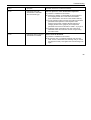
Troubleshooting
Error
Symptom
Possible causes and corrective measures
Message "rotor" appears
in display.
Rotor decelerates with
delayed deceleration.
Set speed exceeds permissible maximum speed for the
rotor. (The same holds for RCF setting)
A) For about 15 sec. the display shows alternately "rotor" and
the maximum permissible speed or RCF for the installed,
after the rotor identification. Within this period, it is
possible to accept this value by again pressing the "start"
key. The centrifugation will then be continued.
B) Following onset of deceleration you must wait until the
rotor has stopped. By opening and closing the lid you
reset the message "rotor". After entering a permissible
speed you can press start.
Lid not properly closed
Display "OPEN" appears
although lid is closed.
Will not start.
Message "Lid" appears
flashing in the display.
Drive stops.
Lid was opened manually during the run.
Rotor stops without
deceleration to standstill.
The instrument stops without deceleration. If you want to
continue the run, you must switch the instrument off and on
again.
Message "Lift Lid"
appears in the display
Lid does not open
automatically.
The lid has not been unlocked after release.
Open the lid and repeat locking procedure.
1. Avoid laying objects onto the centrifuge lid.
2. Lift the lid slightly.
63
Troubleshooting
Error
Symptom
Possible causes and corrective measures
E-01
Rotor stops without
deceleration to standstill.
Internal program error.
|
E-13
E-14
Instrument cannot be
operated.
Rotor stops with
deceleration to standstill.
Instrument cannot be
operated.
E-15
|
E-16
E-17
64
Overtemperature in the centrifuge tank.
Switch the instrument off and on again. If the error persists,
contact a KENDRO service station.
Rotor stops with
deceleration to standstill.
Instrument cannot be
operated.
Temperature measurement error.
Rotor stops with
deceleration to standstill.
Maximum speed for the rotor identification exceeded.
Instrument cannot be
operated.
E-18
Switch the instrument off and on again. If the error persists,
contact KENDRO service.
Instrument stops with
deceleration to standstill
after short starting-up.
Switch the instrument off and on again. If the problem
persists, contact a KENDRO service station.
Switch the instrument off and on again. If the problem
persists, a contact KENDRO service station.
Bucket code for this rotor is not defined.
Check, whether the bucket is permitted for the inserted rotor
(rotor program, page 16).
Troubleshooting
Error
Symptom
Possible causes and corrective measures
E-19
Instrument stops with
deceleration to standstill
after short starting-up.
No rotor present or rotor identification impossible.
A) Check if a certified rotor is inserted.
B) Please pay attention to the legibility of the inscription of
the swinging bucket rotor cross when it is installed.
(rotor identification must show to the chamber bottom)
C) For the swinging bucket rotor the set bucket type must be
permitted for the operation in the respective rotor.
Please note the hints of chapter "Bucket selection of
swinging bucket rotors" (page 43) and compare the
permitted rotors and rotor buckets in "table 1" on page 16.
D) Following a brief power failure, the rotor could not be
identified. Switch the instrument off and on again using
the mains switch.
E-20
Instrument does not start or
decelerates to standstill.
Rotor cannot be identified.
A) Check if a certified rotor is inserted.
B) Check if the rotor is completely fastened onto the motor
shaft. For this, release the rotor fastening until you can lift
and depress it easily. Now tighten the rotor fastening once
again.
65
Troubleshooting
Error
Symptom
Possible causes and corrective measures
E-21
Instrument does not start or
decelerates to standstill.
No rotor present or rotor identification impossible
A) Check if a certified rotor is inserted.
B) Following a brief power failure, the rotor could not be
identified. Switch the instrument off and on again using
the main switch.
Error in speed measurement
E-22
|
Rotor stops without
deceleration to standstill.
E-23
Instrument cannot be
operated.
E-24
|
Instrument cannot be
operated.
Wrong status information from lid lock.
Instrument decelerates
after a short starting-up.
Motor runs in wrong rotational direction.
E-27
E-28
66
Switch the instrument off and on again. If the error persists,
contact the KENDRO service station
Switch the instrument off and on again. If the error persists,
contact the KENDRO service station.
Switch the instrument off and on again. If the error persists,
contact the KENDRO service station.
Troubleshooting
Error
Symptom
Possible causes and corrective measures
E-29
Motor does not start.
Motor or rotor blocked.
1. Switch instrument off and on again using the main switch.
2. Open the lid.
3. Check whether the rotor can turn freely.
If you cannot clear the malfunction, contact the KENDRO
service station.
E-30
E-31
Rotor stops without
deceleration to standstill or
does not start.
Control voltage breaks down.
Rotor stops without
deceleration to standstill or
does not start.
Overtemperature in the motor.
Switch the instrument off and on again. If the error persists,
contact the KENDRO service station.
.
E-32
Rotor stops without
deceleration to standstill or
does not start.
1. Turn instrument off and unplug mains power cord.
2. Check and clean ventilation slots if necessary.
3. After about 60 min. you can restart the instrument.
Observe the max. permissible environmental temperature!
If the error persists, contact the KENDRO service station.
Overtemperature in the electronics.
1. Turn instrument off and unplug mains power cord.
2. Check and clean ventilation slots if necessary.
3. After about 60 min. you can restart the instrument.
Observe the max. permissible environmental temperature!
If the error persists, contact the KENDRO service station.
67
Troubleshooting
Error
Symptom
Possible causes and corrective measures
E-33
Rotor stops without
deceleration to standstill or
does not start.
Overpressure in the refrigeration system
1. Turn instrument off and pull main plug.
1. Check and clean ventilation slots if necessary.
2. After about 60 min. you can restart the instrument.
Observe the max. permissible environmental temperature!
If the error persists, contact the KENDRO service station.
E-34
Rotor stops without
deceleration to standstill or
does not start.
Overvoltage in the intermediate circuit.
Rotor stops without
deceleration to standstill or
does not start.
Overcurrent in the intermediate circuit.
E-36
|
Rotor stops without
deceleration to standstill.
Overcurrent or error in current measurement.
E-38
Instrument cannot be
operated.
E-39
Rotor stops without
deceleration to standstill.
Speed control measurement exceeds permissible rotor
speed.
Instrument cannot be
operated.
Switch the instrument off and on again.
If the error persists, contact the KENDRO service station.
E-35
68
Switch the instrument off and on again.
If the error persists, contact the KENDRO service station.
Switch the instrument off and on again. If the error persists,
contact the KENDRO service station.
Switch the instrument off and on again.
If the error persists, contact the KENDRO service station.
Troubleshooting
Error
Symptom
Possible causes and corrective measures
E-40
Rotor stops without
deceleration to standstill.
Acceleration of rotor too slow
Instrument cannot be
operated.
Significant imbalance caused by missing bucket
Tubes or adapter do not fit
(rotor is rubbing the chamber or the cover)
- Micro plates carriers on the motor cover
If the error persists, contact the KENDRO service station.
Open the lid and check the load!
-
69
Troubleshooting
Contacting Kendro Service
Should you require help from our service station,
please indicate the catalog and serial number of your
instrument. You will find the pertinent information at the
specifications, near the socket for the main plug.
Moreover it is helpful for our service representative to
know your software version. You can determine the
software version as follows:
1. Switch the instrument off.
2. Keep selection key
pressed and switch on the
instrument
For about 1 sec all displays read:
Subsequently, the following readings will be displayed for 5 seconds each:
(Numbers are examples)
Software version keyboard
__526
__2
Software version
__528
_4468
__6
NV-RAM version
The value in the time panel indicates the development
stage.
The last information displayed indicates the current
cycle status.
Cycle counter
__235 _CY
The values given are only examples!
During the subsequent program test, the message
_ TEST PRO / 4 ... 1* is displayed.
(* only for instruments with refrigeration system)
70
__7
Technical Data
Technical Data
Features
Specification
Ambient conditions
- indoor use
- maximum elevation 2000 m (6562 ft) above sea level
- max. relative humidity 80 % up to 31°C (88°F), linearly decreasing
down to 50 % relative humidity at 40°C (104°F).
Ambient temperature allowed
+2 °C to +40 °C
run time
- standard mode :
- extended mode :
maximum speed (nmax)
15 000 rpm (rotor-dependent, adjustable in steps of 10)
minimum speed (nmin)
300 rpm
maximum RCF
(36°F to 104°F)
1min – 9 h 59 min, hold = permanent
1min – 99 h, hold
24 652
(micro liter rotor 48 x 2ml 7500 3348)
maximum kinetic energy Multifuge 1 S
®
Multifuge 1 S-R
34.3 kNm
34.3 kNm
(25 298 ft.lb)
(25 298 ft.lb)
noise at maximum speed Multifuge® 1 S
®
Multifuge 1 S-R
< 64 dB (A)
< 54 dB (A)
(sound pressure level of emission according to DIN EN ISO 11 201)
Temperature set range
-9 °C to +40 °C
®
Dimension (H x W x D)
Multifuge® 1 S
®
Multifuge 1 S-R
365 mm x 500 mm x 615 mm
365 mm x 686 mm x 665 mm
( 14.37 x 19.69 x 24.21 inches )
( 14.37 x 27.0 x 26.18 inches )
71
Technical Data
Features
Weight without rotor
Specification
Multifuge® 1 S
®
Multifuge 1 S-R
Testing standards
- all devices manufactured and examined in
agreement with:
92 kg
118 kg
( 203 lb )
( 259 lb )
IEC 61010-1:1990 + amendment 1:1992 + amendment 2:1995
IEC 61010-2-020:1993 + amendment 1:1996
- Pollution degree 2, - Overvoltage category II
- for 120 V only
- for 230 V only
72
CAN/CSA-C22.2 No. 1010-1.92
CAN/CSA-C22.2 No. 1010-1.B97 amendment 2
UL 3101-1
EN 292
EN 61 010-1, EN 61 010-2-020
EN 61326, EN 55011 B
Technical Data
Electrical connections / fuses
Order no.
Voltage
Frequency
Nominal
current
Power
consumption
Fuse protection of
instrument
- safety fuse
Fuse
protection of
building
* thermal excess current
release
Multifuge® 1 S
7500 4311
230 V
50/60 Hz
Multifuge® 1 S
7500 4315
120 V
60 Hz
Multifuge® 1 S-R
7500 4331
230 V
50/60 Hz
Multifuge® 1 S-R
7500 4335
120 V
60 Hz
9.1 A
1300 W
12 A
* 14 A
16 AT
12.0 A
1200 W
12 A
* 16 A
15 AT
9.2 A
1520 W
12 A
* 14 A
16 AT
12.0 A
1440 W
12 A
* 16 A
15 AT
73
Notes
74
Appendix
Acceleration and deceleration profiles
On the following pages you find acceleration and deceleration profiles for each rotor type respectively.
75
Acceleration profiles
Swinging Bucket Rotor TTH 400 75002000
9
1
5000
speed [rpm]
4000
3000
2000
1000
0
0
30
60
90
120
time [s]
76
150
180
210
Deceleration profiles
Swinging Bucket Rotor TTH 400 75002000
5000
speed [rpm]
4000
3000
2000
1000
0
0
30
60
90
120
9
150
180
210
1
time [s]
77
Acceleration profiles
BIOshield® 600 Rotor 75002005
9
1
6000
speed [rpm]
5000
4000
3000
2000
1000
0
0
30
60
90
120
time [s]
78
150
180
210
240
Deceleration profiles
BIOshield® 600 Rotor 75002005
6000
5000
speed [rpm]
4000
3000
2000
1000
0
0
30
60
90
120
9
150
180
210
1
time [s]
79
Acceleration profiles
Micro plate carrier MP 3300 75002010
9
1
speed [rpm]
4000
3000
2000
1000
0
0
30
60
90
120
time [s]
80
150
180
210
Deceleration profiles
Micro plate carrier MP 3300 75002010
4000
speed [rpm]
3000
2000
1000
0
0
30
9
60
90
time [s]
120
150
180
1
81
Acceleration profiles
Fixed-Angle Rotor FA12.94 Highconic®
7500 2006
9
1
11000
10000
9000
8000
speed [rpm]
7000
6000
5000
4000
3000
2000
1000
0
0
30
60
90
120
time [s]
82
150
180
210
240
7500 2006
speed [rpm]
Deceleration profiles
Fixed-Angle Rotor FA12.94 Highconic®
9
time [s]
1
83
Acceleration profiles
Micro Liter Rotor 48 x 2 ml 75003348
9
1
16000
14000
12000
speed [rpm]
10000
8000
6000
4000
2000
0
0
30
60
90
120
time [s]
84
150
180
210
240
Deceleration profiles
Micro Liter Rotor 48 x 2 ml 75003348
16000
14000
12000
speed [rpm]
10000
8000
6000
4000
2000
0
0
30
9
60
90
120
150
time [s]
180
210
240
270
1
85
86
Speed/RCF diagrams
* nmax = max. speed
Speed/RCF diagram
Swinging Bucket Rotor TTH 400
75002000
RCF [x g]
10000
1000
Round bucket
Rectangular bucket
nmax = 4700 rpm
RCFmax = 4618
100
10
100
1000
10000
speed (rpm)
87
Speed/RCF diagram
BIOshield® 600 Rotor
75002005
10000
nmax = 6000 rpm
RCF (rmax nmax) = 6842
RCF [x g]
1000
100
10
100
1000
speed (rpm)
88
10000
Speed/RCF diagram
Micro plate carrier MP 3300
75002010
10000
nmax = 4400 rpm
RCF (rmax nmax) = 3355
RCF [x g]
1000
100
10
100
1000
10000
speed (rpm)
89
Speed/RCF diagram
Fixed-Angle Rotor FA12.94 Highconic®
100000
7500 2006
rmax = 12.5 cm
rmin = 6.1 cm
nmax = 10 350 rpm
RCF (rmax nmax) = 15 090
RCF [x g]
10000
1000
100
10
1
100
1000
10000
speed (rpm)
90
100000
Speed/RCF diagram
Micro liter Rotor 48 x 2 ml
7500 3348
100000
10000
nmax = 15 000 rpm
RCF (rmax nmax) = 24 652
rmax = 9.8 cm
rmin = 5.9 cm
RCF [x g]
1000
100
10
1
100
1000
10000
100000
speed (rpm)
91
92
Index
A
C
acceleration and deceleration curves · 75
acceleration profiles · 7
Acceleration/decelaration profile · 10
actual values · 44
adapter · 24
aerosol-tight operation · 32
aerosol-tightness
test · 36
aluminum rotor: · 55
approved rotors · 38
audible signal
can be switched on or off · 52
switching on/off · 52
autoclaving · 56
autoclaving cycle
permissible maximum · 56
centrifuge exceptionally noisy · 62
Centrifuge transport and installation · 13
Centrifuging with a program · 50
changing settings
during run · 48
cleaning · 53
closing the lid · 37
collet chuck · 38
common glass or plastic centrifuge tubes · 4
conditions of warranty · 57
Conformity · 5
contamination
necessary measures · 54
continuous operation · 46
control panel
readings · 7
corrosion · 4
corrosive substances
protective tubes for corrosive substances · 4
cycle counter · 70
B
bAL · 48
Basic unit/ function · 9
93
D
dangerous chemicals · 3
Deceleration curves · 43
deceleration profiles · 7
decontamination · 54
Description · 7
Description / feature · 9
Diagnostic messages · 11
disinfectant · 55
disinfection · 4
procedure · 55
disinfection with bleaching lye · 55
displays
brief failure · 61
error codes
„bAl“ · 62
E-01 ... E-40 · 64
F
filling the centrifuge tubes · 40
fixed run time · 45
G
general view · 7, 8, 15, 16, 18, 19, 20, 22, 23
goes forward · 48
E
H
EASYsetTM
user interface · 10
EASYset™ control panel · 7
Emergency lid release · 59
Entering parameters · 43
Entering/changing a program · 50
error codes
„Lid“ · 63
„OPEN“ with lid closed · 63
„rotor“ · 63
handling the centrifuge · 4
hazardous substances · 3
hazards
symbols · 5
hints
symbol · 5
hLd · 45, 46
94
I
M
icons
for denoting dangers and potential damage · 5
imbalance · 40, 41
imbalance · 48
imbalance detection · 8
indoor use · 13
infectious material
precautions in case of tube breakage · 54
Inserting the centrifuge tubes · 41
Installing the rotor · 38
maintenance · 53
manual lid unlocking · 59
manual stopping · 49
max. tube dimensions · 25
maximum filling volume · 35
Maximum loading · 39
maximum permissible filling volume · 34
maximum permissible RCF · 48
maximum permissible speed · 48
Maximum RCF value · 16, 17, 21
maximum sample density · 3
microtest plates · 31
minimum distance
from wall · 13
L
lid
blockage · 61
Lid lock with safety check · 8
lid opening · 37
lid release Emergency · 59
lid unlocking mechanism
manual · 59
limited life time · 40
location · 13
O
opening the lid · 37
operation
short-time · 51
organic solvents
not allowed for cleaning · 54
95
P
pathogenic microorganisms
protection against · 4
Plastic sample tubes
Pretemp function · 47
pretemperature-regulations · 47
problems
handling · 61
program display
symbols · 50
Program memory keys · 10
program storing · 50
protective tubes
for corrosive substances · 4
Q
quick run function · 51
Quick run mode · 11
R
radius of centrifugation
for calculation of RCF value · 45
RCF
maximum · 48
96
RCF / speed display · 43
RCF display
and rotor identification · 44
RCF selection · 10
RCF setpoint · 44
RCF value · 7, 45
relative centrifugal force · 45
RCF-value · 20, 22, 23
RCF-value · 18, 19
readings
of control panel during run · 7
Regulations for prevention of accidents · 5
relative centrifugal force · 45
remain dark · 61
rotor cover · 38
rotor identification · 8
rotor identification · 44
and RCF display · 44
Rotor program for the Multifuge · 16
rotors
approved · 38
run profile · 7
run time
range · 45
selection · 45
S
safety instructions · 3
Safety instructions · 5
safety measures · 3
safety standards · 5
safety zone · 3, 13
sample density
maximum · 3
sample tubes are approved · 40
selecting
run time · 45
Selecting speed · 44
selecting the
temperature · 47
Selecting the temperature · 47
service · 57
service contracts · 57
setpoint values · 44
setting
speed · 44
settings
change during run · 48
Short time centrifugation · 51
short-time operation · 51
signal · 52
software check
internal · 37
software version
determination · 70
speed
maximum · 48
speed / RCF display · 43
speed of centrifugation
for calculation of RCF value · 45
Speed selection, · 10
speed setting · 44
Starting the centrifuge · 48
stopping
manually · 49
with continuous operation · 49
Stopping
with preset run time · 49
substructure · 13
Switching from speed to RCF display and vice versa · 43
symbols
for hazards and dangers · 5
T
Technical Data · 71
test
aerosol-tightness · 36
The printed documents consist of the delivery notes and
this Manual · 8
time
counted forward in quick run mode · 51
tools for installing the rotor · 38
toxins
protection against · 4
troubleshooting · 59
t-set
97
time mode · 46
tube
breakage with infectious material · 54
Turning the centrifuge off · 52
V
volume
98
maximum filling · 35
W
warning signal · 52
warranty conditions · 57
wear · 4
For Ordering or Technical Information
Asia Pacific
Kendro Laboratory Products International Sales · Asheville, NC · USA · Tel. +1 828-658 2711 · Fax +1 828-645 7581 · [email protected]
Europe, Middle East, Africa
Kendro Laboratory Products International Sales · Langenselbold · Germany · Tel. +49 (0) 6184-90 6940· Fax +49 (0) 6184-90 7474 ·
[email protected]
Latin America Kendro Laboratory Products International Sales · Asheville, NC · USA · Tel. +1 828-658 2711 · Fax +1 828-645 7581 · [email protected]
North America Kendro Laboratory Products International Sales · Asheville, NC · USA · Tel. +1 828-658 2711 · Fax +1 828-645 3368 · [email protected]
Sorvall and Heraeus products · Tel. +1 800-522 7746
Internet
http://www.kendro.com
Kendro Laboratory Products GmbH
Robert-Bosch-Straße 1
D-63505 Langenselbold
Telephone: +49 (0) 6184 90 6940
In the interest of continuous product development, we
reserve the right to make changes without express
notice.
20058041
Multifuge 1S/1S-R_uk 04/04
Printed in Germany