1
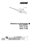
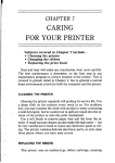
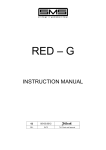
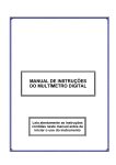
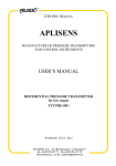
USER
MANUAL
MODEL 2036P
High Speed
Parallel to Serial/
Serial to Parallel
Interface Converter
Part #07M2036P-C
Doc. #102142UC
Revised 6/8/98
CERTIFIED
An ISO-9001
Certified Company
SALES OFFICE
(301) 975-1000
TECHNICAL SUPPORT
(301) 975-1007
http://www.patton.com
1.0 WARRANTY INFORMATION
1.3 SERVICE
Patton Electronics warrants all Model 2036P components to be
free from defects, and will—at our option—repair or replace the products should they fail within one year from the first date of shipment.
This warranty is limited to defects in workmanship or materials,
and does not cover customer damage, abuse or unauthorized modification. If these products fail or do not perform as warranted, your sole
recourse shall be repair or replacement as described above. Under no
condition shall Patton Electronics be liable for any damages incurred
by the use of these products. These damages include, but are not limited to, the following: lost profits, lost savings and incidental or consequential damages arising from the use of or inability to use this product. Patton Electronics specifically disclaims all other warranties,
expressed or implied, and the installation or use of this product shall
be deemed an acceptance of these terms by the user.
All warranty and non-warranty repairs must be returned freight
prepaid and insured to Patton Electronics. All returns must have a
Return Materials Authorization number on the outside of the shipping
container. This number may be obtained from Patton Electronics
Technical Support: (301) 975-1007; http://www.patton.com; or, [email protected].
NOTE: Packages received without an RMA number will not be
accepted.
Patton Electronics' technical staff is also available to answer any
questions that might arise concerning the installation or use of your
Model 2036P. Technical Support hours: 8AM to 5PM EST, Monday
through Friday.
1.1 RADIO AND TV INTERFERENCE
The Model 2036P generates and uses radio frequency energy,
and if not installed and used properly—that is, in strict accordance with
the manufacturer's instructions—may cause interference to radio and
television reception. They have been tested and found to comply with
the limits for Class A computing devices in accordance with the specifications in Subpart J of Part 15 of FCC rules, which are designed to
provide reasonable protection from such interference in a commercial
installation. However, there is no guarantee that interference will not
occur in a particular installation. If they do cause interference to radio
or television reception, which can be determined by disconnecting the
RS-232 interface, the user is encouraged to try to correct the interference by one or more of the following measures: moving the computing equipment away from the receiver, re-orienting the receiving antenna and/or plugging the receiving equipment into a different AC outlet
(such that the computing equipment and receiver are on different
branches).
1.2 CE NOTICE
The CE symbol on your Patton Electronics equipment indicates
that it is in compliance with the Electromagnetic Compatibility (EMC)
directive and the Low Voltage Directive (LVD) of the Union European
(EU). A Certificate of Compliance is available by contacting Technical
Support.
1
2
2.0 GENERAL INFORMATION
3.0 CONFIGURATION
Thank you for your purchase of this Patton Electronics product.
This product has been thoroughly inspected and tested and is warranted for One Year parts and labor. If any questions or problems arise
during installation or use of this product, please do not hesitate to contact Patton Electronics Technical Support at (301) 975-1007.
The Model 2036P is simple to install and designed for excellent
reliability. The following instructions will help you set up and install
your converter properly. If you have any questions, please call Patton
Technical Support at (301) 975-1007.
3.1 CONFIGURATION SWITCHES
2.1 FEATURES
• Converts parallel data to serial data and vice versa
• Automatically selects parallel-to-serial and
serial-to-parallel operation
• Automatically selects DCE/DTE modes
• Serial data rates to 115,200 bps
• Supports both software and hardware flow control
• Interface or AC Powered
• Ultra-miniature size
• Made in the USA
The Model 2036P uses a set of eight internal DIP switches (see
Figure 1) that allow configuration to a wide range of applications. You
must open the case to gain access to the internal switches. To open
the case, insert a small screwdriver into one of the slots on the side of
the plastic case. Then twist from side to side until the case opens.
The configuration switches allow you to select data rates, parity,
word length and flow control selection. The following section describes
all switch locations, positions and functions.
Parallel Port
Serial Port
DIP Switches
2.2 DESCRIPTION
For easy configuration, the Model 2036P features a convenient set
of configuration switches. These internally accessible configuration
switches allow the user to control baud rate, parity, word length and
flow control.
Housed in a miniature ABS plastic case, the Model 2036P comes
equipped with a DB-25 female connector on the serial side and a
Centronics 36 pin male connector on the parallel side. Able to recieve
power directly from the RS-232 interface, the Model 2036P also comes
with a wall-mount power supply for low power applications.
1 2345678
The Patton Model 2036P Serial to Parallel and Parallel to
Serial Converter automatically converts RS-232 serial data to parallel
data format and vice versa. Incorporating advanced microprocessor
technology, the 2036P automatically senses and selects parallel and
serial modes, as well as DCE/DTE modes. The Model 2036P supports
serial data rates to 115.2 Kbps.
PATTON
102041K
XXXX
OFF -------- ON
Power Supply Jack
Figure 1. The Location of the Model 2036P Configuration Switches
To configure your unit, use a small screwdriver and gently push
each switch to its proper setting. The ON and OFF positions are
shown in Figure 2. Default settings for the DIP switches are shown in
the table on the following page. Detailed settings follow the table.
ON
DHS-8
1 2 3 4 5 6 7 8
OFF
OFF
Figure 2. The miniature configuration switch package
3
4
DIP SWITCH SUMMARY TABLE
Switch 3 through 5: Data, Parity and Stop Bit
Position
Function
Factory Default
SW1
Flow Control
Off
Hardware
SW2
Bit Error Rate Test
Off
De-Activated
SW3
Data, Parity, Stop Bits
Off
SW4
Data, Parity, Stop Bits
Off
SW5
Data, Parity, Stop Bits
Off
SW6
Data Rate
Off
SW7
Data Rate
Off
SW8
Data Rate
Off
}
}
8B, NP, 1S
38400 bps
3.2 CONFIGURATION SWITCHES SW1 - SW8
Switches 3 through 5 are used to specify the data, parity and stop
bits. The following table shows the settings that may be used:
Data
Parity
Stop
Bit
SW3
SW4
SW5
7B
7B
7B
7B
7B
8B
8B
8B
EP
OP
NP
EP
OP
EP
OP
NP
1S
1S
2S
2S
2S
1S
1S
1S
ON
OFF
ON
OFF
ON
OFF
ON
OFF
ON
ON
OFF
OFF
ON
ON
OFF
OFF
ON
ON
ON
ON
OFF
OFF
OFF
OFF
This section provides detailed information about the function of
each DIP switch and lists all possible settings.
Switch 1: Hardware/Software Control/BERT Direction
Switches 6 through 8: Frequency and Data Rate
The setting for Switch 1 determines whether the 2036P uses hardware or software (i.e. XON/XOFF) flow control. Switch 1 is alternatively used to determine the direction of the BERT output message whenever the BERT is activated (See Switch 2, below).
Switches 6 through 8 determine the frequency and data rate. The
following chart shows the settings that may be used:
Serial Data Rate
Flow Control SW1
Hardware
OFF
Software
ON
BERT Direction SW1
Parallel
OFF
Serial
ON
Switch 2: Bit Error Rate Test (BERT)
Use Switch 2 to activate a Bit Error Rate Test (BERT) in the direction of the serial or parallel interface. This test can be used to determine whether the 2036P is working properly. When BERT is activated,
the 2036P outputs the following Barber Pole pattern, which represents
every ASCII character on a standard US keyboard:
Data Rate
SW6
SW7
SW8
1200
2400
4800
9600
19200
38400
57600
115200
OFF
ON
ON
OFF
ON
OFF
ON
OFF
OFF
OFF
ON
ON
ON
OFF
OFF
ON
ON
ON
OFF
ON
ON
OFF
OFF
OFF
0123456789:;<=>?@ABCDEFGHIJKLMNOPQRSTUVWXYZ[\}^_’abcdefghijklmnopqrstuvwxyz{|}~
Bit Error Rate
BERT Activated
BERT De-activated
SW2
ON
OFF
NOTE: When you activate the BER Test, the 2036P “memorizes” the setting of
Switches S1, S3,S4, S5, S6, S7, and S8 to perform the test. If you modify any of
these switches, you must de-activate Switch 2 in order for the changes to take effect.
5
6
4.0 INSTALLATION
APPENDIX A
The Patton Model 2036P are very simple to install. Once you
have configured the DIP switches, just plug your converter in to a standard cable and you’re ready to go. Figure 3 illustrates the proper connections for the Model 2036P. If you have special-ordered a non-standard connector, your connections may be different.
PATTON MODEL 2036P SPECIFICATIONS
Interface:
Asynchronous, RS-232C compatible
Connectors:
Serial, DB-25 female; Parallel,
Centronics 36 pin male
Data Rates:
0 - 115,200 Kbps
Power Supply:
1) Uses power from RS-232 interface;
2) 9VDC, 500mA power supply;
3) Typical Maximum power consumption
= 100mW @5V (20mA)
Flow Control:
[Serial Side as DCE = CTS (5)/DSR (6)]
[Serial Side as DTE = DTR (20)]
Data Format:
7 or 8 bits; 1 or 2 stop bits; even, odd or no
parity
Serial Interface
Model 2036P
Your cable
Printer
PC
Parallel Interface
Pigure 3. Installing the Model 2036P
Temperature Range: 0-50°C (32-140°F)
4.1 POWER CONNECTION
In many cases, the Model 2036P will run without being connected
to external power. However, additional power may be necessary in
certain applications that use low power RS-232 devices.
The 120VAC U.S. wall transformer version supplies +9V regulated
DC up to 500mA. Connect this wall transformer to the Model 2036P
by means of a cannon jack on the side panel. The Model 2036P is
powered-up as soon as it is plugged into an AC outlet–there is no
power switch.
Altitude:
0-10,100 feet
Humidity:
5 to 95% non-condensing
Dimensions:
4.35” x 2.9” x 0.8” (11.0mm x 7.4mm x
2.0mm)
Weight:
2.6 oz. (73.8 grams)
5.0 OPERATION
Once your interface converter is properly configured and installed,
it should operate transparently—as if it were a standard cable connection. Operating power is derived from the RS-232 data and control signals; there is no “ON/OFF” switch.
7
8
APPENDIX B
APPENDIX C
PATTON MODEL 2036P INTERFACE CONNECTIONS
PATTON MODEL 2036P
FACTORY REPLACEMENT PARTS AND ACCESSORIES
36 PIN CENTRONICS PARALLEL PORT CONNECTIONS
Pin
1
2
3
4
5
6
7
8
9
10
11
12
13
18
32
Description
Direction
Description
Patton Model #
Strobe
Output
Data bit 0
Data bit 1
Data bit 2
Data bit 3
Data bit 4
I/O
Data bit 5
Data bit 6
Data bit 7
Acknowledge
Input (active low)
Busy
Input (active high)
Paper end
Select
+5 volts
Error
(tied to +5V)
(16, 17, 19, 20, 21, 22, 23, 24,
Ground
25, 26, 27, 28, 29, 30, 33, 36)
}
08059DCI ........................230VDC (+9V ±5% reg. DC/500mA)
International Adapter
0805B ..............................110VDC (+9V ±5% reg. DC/500mA)
American Adapter
07M2036P .......................User Manual
}
Note: All other pins are unconnected
DB-25 PORT CONNECTIONS
Pin Name
Description
1
2
3
FG
TXD
RXD
4
RTS
5
6
CTS
DSR
7
8
9
20
SG
DCD
+V in
DTR
Connected to pin 7
Transmit Data; Power source when conn. to DTE
Receive Data (sends XON/XOFF only); Power
source when connected to DCE
Request to Send; Power source when connected
to DTE
Clear to Send; Power source when conn. to DCE
Data Set Ready; Power source when conn.
to DCE
Signal Ground
Carrier Detect; Power source when conn. to DCE
Used as an external power source
Data Terminal Ready; Power source when conn. to
DTE
Note: All other pins are unconnected
9
10
APPENDIX C
PATTON MODEL 2036P BLOCK DIAGRAM
Copyright © 1998
Patton Electronics Company
All Rights Reserved
11