1
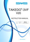
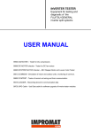
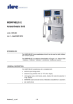
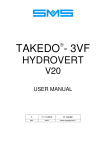
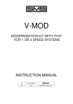
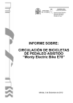
RED – G
INSTRUCTION MANUAL
02
05-03-2012
REL.
DATE
T.M. Check and Approval
INDEX
1 - INTRODUCTION ......................................................................... ...Page 3
2 - GENERAL DESCRIPTION .............................................................Page 3
3 - OPERATION PRINCIPLE ..............................................................Page 3
4 - INSTALLATION ..............................................................................Page 4
5 - WIRING DIAGRAM ........................................................................Page 5
6 - SETTINGS, ADJUSTMENTS AND SIGNALS ................................Page 6
7 - OPTIONAL CONNECTIONS TO INSTALL RED-G
IN EXISTING LIFTS (RGOPA BOARD) ........................................Page 7
8 - FINAL CHECK AND TEST .............................................................Page 8
9 - TROUBLE SHOOTING ..................................................................Page 8
10 - TROUBLE SHOOTING ..................................................................Page 9
11 - DIMENSIONS AND WEIGHT .........................................................Page 10
2
RED-G USER MANUAL Release 02- 05-03-2012
1 – INTRODUCTION
RED-G is an automatic rescue device for lift systems equipped with inverter: rope lifts, both with
asynchronous and synchronous motors, or hydraulic lifts.
RED-G has to be installed on the 3-phase 400Vac mains; in case of power failure, it fully supplies the lift
system with the necessary power to move the car at reduced speed, in any direction and in any load
condition.
RED-G is supplied by batteries and it has got a sine wave and stabilized output voltage, so it is suitable for
any lift installation.
An optional board makes it easy to install even in existing lifts, which were not prearranged for the
emergency operation.
RED-G is built-up in a short depth metal box, to be installed directly on the lift shaft, and it is pre-wired for the
easiest and fastest connection.
This manual provides you the necessary information about wiring, put on service and the operation
of RED-G, please read it carefully before going on with the installation.
2 – GENERAL DESCRIPTION
RED-G is available in two sizes:
- SIZE 1
Output Voltage:
3~400Vac
Power: 2kW for 15’, Allowed Overload: 3kW for 1’
Battery Supply:
48V (N°4 Batteries series connect ed, 12V 18Ah)
- SIZE 2
Output Voltage:
3~400Vac
Power: 4kW for 15’, Allowed Overload: 6kW for 1’
Battery Supply:
96V (N°8 Batteries series connect ed, 12V 18Ah)
The device is built-up in a metal box and it’s made up of the following components:
battery-charger, three-phase inverter, L/C filter, elevator transformer and the contactors that switch the power
supply.
The BATTERIES must be placed outside the metal box.
3 – OPERATION PRINCIPLE
RED-G detects the mains power failure (even of a single phase) and after a few seconds the rescue
operation starts:
- The power supply, which normally comes from the mains, is cut.
- Next, the 3-phase inverter switches on in order to reproduce the mains supply voltage, through the
elevator transformer and the L/C filter. It supplies the control panel with the necessary power to move the
car at reduced speed. This speed is simply obtained using a “voltage free” contact of <rescue operation in
progress> available in RED-G (if the control panel is prearranged for this operation), or adding an optional
board that drives the control panel to run a controlled reset travel operation, that stops at the first floor
reached.
- RED-G ends its operation and shuts down after an adjustable time after the car stops at floor, in order to
allow the automatic door to open, so the people in the car can easily go out.
- When the RED-G operation comes to an end, the lift system is put again in the original operation
condition, connected to the mains.
A new rescue operation would be carried out only after the mains supply comes back and then it misses
again.
RED-G can be also activated with an external input to move the car both with the presence or the absence of
the mains power supply.
RED-G USER MANUAL Release 02- 05-03-2012
3
4 – INSTALLATION
RED-G is pre-wired and can be easily wall-mounted, near the control panel or in the shaft (in case of MRL lift
system).
The connections must be carried out with the Mains Power Switch and Car Light Switch of the lift system,
and the RED-G Main Switch IE all open, following the WIRING DIAGRAM in paragraph 5), taking into
consideration the following clarifications:
- Connect the 1~230V 50Hz battery-charger supply to the terminals LL – NN (BROWN-LIGHT BLUE
wires).
- Connect the batteries in series and the terminals B+ – B- (RED – BLACK wires) to the batteries, as
shown in the following drawing:
B- WIRE
(BLACK)
B+ WIRE
(RED)
-
-
-
-
-
4
+ -
+ -
+ -
+
Cut off the lift system main power, connecting the 3-phase MAINS and the NEUTRAL to the terminals
L1 – L2 – L3 – LN of RED-G (BROWN (3-phase mains) + LIGHT BLUE (neutral)), and the supply voltage
of the lift system (control panel) to the terminals Q1 – Q2 – Q3 – QN (GRAY (3 phases) + LIGHT BLUE
(neutral)).
Connect the wires YELLOW/GREEN to the EARTH.
Connect the terminals S1-S2 (ROSSO wires) to the 4th pole of the Mains General Switch.
If the 4th pole is open, the rescue operation is disabled.
Connect the terminals F+ – F- (PURPLE – PURPLE/BLACK wires) in parallel to the motor brake coil.
Respect the polarities, connecting the positive terminal to F+.
If you need, connect the terminals ON – ON (GREEN wires) to an external contact to control the forced
activation or the TEST of the RED-G device: when this command goes on, RED-G will perform a full
emergency cycle, using the voltage provided by the batteries if the Dip Switch SW1 – 5 is OFF, or using
the mains voltage if the Dip Switch SW1 – 5 is ON (See Paragraph 6).
On the terminals CM1 – NO1 – NC1 (WHITE wires) and CM2 – NO2 – NC2 (BLACK wires) 2 switching
contacts of the KE relay are available; the KE relay is ON during the whole emergency cycle, so these
contacts can be used to give the emergency command to the control panel and to the inverter, in order to
make the car move at low speed.
On the terminals FL1 – FL2 (ORANGE wires) a N.O. contact of the FA relay is available; in the standard
configuration, the FA relay works as <READY> (it is always closed, except when RED-G detects a
malfunction or a failure.
If you need, you can use the N.C. contact, moving the connector from CN17 to CN16 son the RGCON
board.
As an alternative, the FA relay con work as <RESCUE OPERATION IN PROGRESS> (energized during
the whole emergency cycle), setting the Dip Switch SW1 – 3 in ON position (See Paragraph 6).
RED-G USER MANUAL Release 02- 05-03-2012
5 – WIRING DIAGRAM
RED-G USER MANUAL Release 02- 05-03-2012
5
6 – SETTINGS, ADJUSTMENTS AND SIGNALS
The Dip Switch SW1 used for the RED-G SETTINGS, the ADJUSTMENT Trimmer and the SIGNAL Leds are
placed in the RGCON control board.
RGCON BOARD LAYOUT
CC
RS
RI
ST
4P
RI: Forced Activation
Command
CT: Contactor Activation Control
CT
BT
th
4P: 4 Pole
CC: Contactor Command
ST, RS : 3-phases
Mains Monitor
SW1: See description
below
BT: Brake Voltage
SW1
ON
FA
KE: Emergency
In Progress
5V: Control Circuit
Supply
1 2 3 4 5 6 7 8
KE
P2
Led A, Led B: Diagnostics
See description below
P3
FA: RED-G
OK
UA
VA
B
WA
P1
A
UA, VA, WA: 3-PHASE INVERTER
Output Monitor
P3: Not Used
P2: Set-up switch
simulation delay,
from 0 to 2,5 sec
P1: Shut off delay
after brake opening,
from 10 to 40 sec
5V
DIP switch SW1
1 (*)
2 (*)
3
4 (*)
5
6
7
8
NOTE (*):
Description
OFF: SET-UP SWITCH ACTIVATION DELAY
ON: SET-UP SWITCH ACTIVATION DELAY
DISABLED
ENABLED
OFF: SET-UP SWITCH SIMULATION ACTIVATING
ON: SET-UP SWITCH SIMULATION ACTIVATING
THE KD OUTPUT
THE KS OUTPUT
OFF: “FA” OUTPUT WORKS AS <READY>
ON: “FA” OUTPUT WORKS AS
(RED-G OK)
<RESCUE OPERATION IN PROGRESS>
OFF: STOP ZONE SWITCH (EVENTUAL)
ON: STOP ZONE SWITCH (EVENTUAL)
WITH N.C. CONTACT
WITH N.O. CONTACT
OFF: OPERATION TEST PERFORMED USING
ON: OPERATION TEST PERFORMED USING
BATTERY VOLTAGE
MAINS VOLTAGE
OFF: RESCUE OPERATION STARTS AFTER 4
ON: RESCUE OPERATION STARTS AFTER 8
SECONDS FROM THE POWER FAILURE
SECONDS FROM THE POWER FAILURE
NOT USED
NOT USED
The switches 1 – 2 – 4 are meaningful only when the RGOPA optional board is used, to install RED-G in an existing lift
system, for the proper adjustment please refer to the next paragraph 7.
Led A
Led B
Description
th
RED-G not ready (4 Pole open)
Notes
RED-G ready to rescue operation
Rescue operation in progress
Rescue operation ended
Maximum operating time expired
Contactors “locked on”
Contactors not energized
Wrong Battery voltage
Wrong Control circuit supply voltage
Inverter Overcurrent
Medium Current too high
Overload
Leds on the FRONT PANEL
GREEN Led
RED Led
6
ON:
RED-G Powered
FLASHING:
Rescue Operation IN PROGRESS
ON:
RED-G has detected a malfunction or a failure
RED-G USER MANUAL Release 02- 05-03-2012
= Led OFF
= Led ON
= Led FLASHING
SLOWo
= Led FLASHING
FAST
7 – OPTIONAL CONNECTIONS FOR INSTALLATION IN EXISTING LIFT SYSTEMS
(RGOPA BOARD)
When RED-G is installed in an existing lift system, it is necessary to add an optional board (RGOPA), to
check the lift operation when you switch on the power supply and to set accordingly RED-G, following the
instructions listed in this paragraph.
The following operations are necessary to assure that, when the lift is controller by RED-G, it runs at low
speed, stops at the next floor and opens the automatic doors.
You must perform the TESTS listed below, following the instructions for a proper setting of RED-G.
Place the lift car within the bottom floor slowing-down zone,
out from the stop zone
WHAT HAPPENS WHEN YOU SWITCH ON THE POWER IN THIS CONDITION?
The car runs in down direction
and stops at bottom floor.
The car runs in up direction.
SW1 – 1 = OFF
SW1 – 2 = OFF
Place the lift car between 2 intermediate floors,
out from the slowing-down zone of the top and bottom floors.
WHAT HAPPENS WHEN YOU SWITCH ON THE POWER IN THIS CONDITION?
The car runs in down direction.
SW1 – 1 = ON
SW1 – 2 = OFF
Moreover, you must add a stop zone
switch, activated when the car
is at any floor level.
SW1 – 4 = ON if N.A. type
SW1 – 4 = OFF if N.C. type
The car runs in up direction.
SW1 – 1 = ON
SW1 – 2 = ON
Moreover, you must add a stop zone
switch, activated when the car
is at any floor level.
SW1 – 4 = ON if N.A. type
SW1 – 4 = OFF if N.C. type
CONNECTIONS
(BLACK) COMS
(WHITE) COMD
UP SET-UP SWITCH
Z1
(RED)
CONTROL
PANEL
Z2
ADDED STOP ZONE
SWITCH
(eventual)
DOWN SET-UP SWITCH
(ORANGE) SV
SQ (ORANGE/BLACK)
DV
(GREEN)
DQ
(WHITE/GREEN)
RED-G USER MANUAL Release 02- 05-03-2012
7
8 – FINAL CHECK AND TEST
Switch on the Main Power Switch, the Auxiliary Light switch, and the IE switch in RED-G.
Check that the lift is working properly, that on the front panel of RED-G the green led is ON and the red one
is OFF, then check on the RGCON board the status of the following leds:
th
- 4P
ON:
4 pole closed
- ST, RS ON:
Mains Power is ON
- FA
ON:
RED-G OK
- A
ON:
RED-G ready to the rescue operation
- 5V
ON:
5V Control circuit supply is ON
In case of installation in existing lifts, be sure that the Switches 1 – 2 – 4 are properly set, according to the
instructions in paragraph 7.
You can now test the emergency operation following the instruction hereunder:
- Make a call for the lift, let it run for a while, then open the Main Power Switch and the Auxiliary Light
switch when the car is between two floors.
th
- Make a jumper between the terminals S1-S2, because if the 4 pole is open, the lift cannot perform the
emergency operation.
After a few seconds, the rescue operation starts, and you can follow the progress checking the led status on
the RGCON board:
a) The Led A turns OFF.
b) The Led B and KE turn ON (rescue operation in progress)
c) The Led CC turns ON, it shows that the KE1 and KE2 contactor coils are supplied.
Then the Led CT turns ON, to show that the contactors are properly energized, and they cut the external
3-phase mains.
d) The 3-phase inverter turns ON (leds UA, VA, WA flashing): the whole lift system is powered again.
e) Then the led BT turns ON, it shows that the motor brake is supplied.
The car runs at low speed and it stops at the next floor, opening the automatic doors.
f) After the de-energization of the motor brake (led BT turns OFF), RED-G waits for the time set with the P1
trimmer.
g) After this time, the 3-phase inverter turns OFF.
h) Then the KE1 and KE2 contactors are de-energized, putting the lift system in the original operation
condition, powered by the Mains.
i) Both Leds A and B turn ON (rescue operation ended).
j) At the end of the rescue operation cycle, with no power still coming from the Mains, the KE relay holds
ON to keep the external fan operating for a maximum time of 2 minutes.
When the Mains Power comes back, the leds RS and ST turn ON and the led B turns OFF. The KE relay, if
still ON, is immediately de-energized.
8.1 – INSULATION TEST INSTRUCTIONS
1. Place the IE switch of RED-G in OFF position.
2. Disconnect the YELLOW/GREEN wire from EARTH.
3. In the same conditions you test the insulation of the different circuits of the control panel, test the
insulation of the circuits of RED-G towards earth and towards the other circuits, on the terminals:
• 400
on TT transformer
• LL
battery-charger supply 1~230Vac
• Red/Black wires at the ends of series connected batteries (0V, 48V)
9 – TROUBLE SHOOTING
1) The rescue operation doesn’t start:
th
Check that the 4 pole is closed.
Check that RED-G is powered (GREEN led on the front panel ON).
Check that RED-G doesn’t show any fault, through the RED led on the front panel and the leds A
and B on the RGCON board.
2) The rescue operation starts, but the car doesn’t run:
Check that the car is not at any floor level.
Check that the control panel commands the set-up operation and that gives the inverter the low
speed command.
Check that RED-G doesn’t show any fault, through the RED led on the front panel and the leds A
and B on the RGCON board.
Check if the phase sequence/missing device of the control panel is working properly.
8
RED-G USER MANUAL Release 02- 05-03-2012
3)
If not, try to invert 2 output phases of RED-G device. If problem persists, use a N.O. contact of
RED-G device to bypass the phase sequence/missing device contact.
The rescue operation ends properly, but door opens from undesidered side:
Lift installation has a double car entrance. Make a copy of the control panel wiring diagram and
contact SMS.
10 – TECHNICAL SPECIFICATIONS
SIZE
BATTERIES
BATTERY CHARGER
OUTPUT 3~
OVERLOAD
1 (2000 VA)
N.4*12V 18Ah
N.1 54V 1.5 A
(230Vac 50Hz +8/-15%)
400Vac +/- 10%,
50Hz, with neutral
3000 VA (1 min.)
2 (4000 VA)
N.8*12V 18Ah
N.2 54V 1.5 A
(230Vac 50Hz +8/-15%)
400Vac +/- 10%,
50Hz, with neutral
6000 VA (1 min.)
Hardware Protections:
- Circuit-breaker 63A (IE)
Software Protections:
- Limit Current peak, medium current too high, overload
- 48V Check: Batteries discharged at 40V, overcharged at 60V
- Rescue Operation Maximum Time: 15 minutes, 1 minute at 50% overload
INPUTS
- Brake Voltage Check:
- Contacts 4P – ON :
Allowed Voltage 48 ÷ 230Vdc +/-10%
Rated Voltage 60Vdc max.
Minimum Switching Current 5mA
OUTPUTS
- Contacts KE – FA – KS – KD: Switching Load
24Vdc/8A
250Vac/8A
110Vdc/0,3A
Minimum Switching Load 5V/5mA
RED-G USER MANUAL Release 02- 05-03-2012
9
11 – DIMENSIONS AND WEIGHT
SIZE
Width
(mm)
Width
with side
handles (mm)
Height
(mm)
Depth
(mm)
Weight
(kg)
1
380
490
520
180
30
2
480
590
600
280
40
FRAME FIXING INSTRUCTIONS (SIZE 1)
Top fixing by means of
N°2 hook anchors
Fix the handle
by means of
N°2 hexagonal screws M6
Fix the handle
by means of
N°2 hexagonal screws M6
Attach the plate to
the side by means of
N°3 screws M5
Attach the plate to
the side by means of
N°3 screws M5
For further information please contact:
SMS SISTEMI e MICROSISTEMI s.r.l. (Gruppo SASSI HOLDING)
Cap. Soc. 260.000€ i.v.
Via Guido Rossa, 46/48/50 40056 Crespellano BO
R.E.A 272354 CF - Reg. Imprese Bo 03190050371 P.IVA IT 00601981202
Tel. : +39 051 969037 Fax : +39 051 969303 Technical Service: +39 051 6720710
Web : www.sms.bo.it E-mail : [email protected]
10
RED-G USER MANUAL Release 02- 05-03-2012