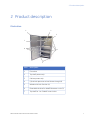
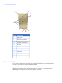
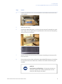
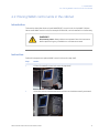
1
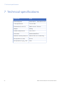
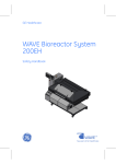
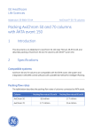
GE Healthcare
WAVE Cabinet 20/50 220-240 V
User Manual
Table of Contents
Table of Contents
1
Important user information ...............................................................................
5
2
Product description .............................................................................................
7
3
Safety precautions ...............................................................................................
10
4
Installation ............................................................................................................
12
4.1
4.2
Placing WAVE Bioreactor units in the cabinet .........................................................................
Placing WAVE control units in the cabinet ................................................................................
13
17
5
Operation ..............................................................................................................
19
6
Maintenance and service ...................................................................................
20
7
Technical specifications ......................................................................................
22
WAVE Cabinet 20/50 User Manual 28-9651-86 AA
3
1 Important user information
1 Important user information
Read this before using WAVE
Cabinet
All users must read the safety instructions in the WAVE Cabinet User Documentation to
fully understand the safe use of the WAVE Cabinet, before installing, using, or performing
maintenance.
Do not operate the WAVE Cabinet in any other way than described in the user
documentation. If you do, you may be exposed to hazards that can lead to personal
injury, and you may cause damage to the equipment.
Intended use
The WAVE Cabinet has been designed to contain BASE20/50 WAVE Bioreactor™
instruments and WAVE control units.
Safety notices
This user documentation contains WARNINGS, CAUTIONS and NOTICES concerning the
safe use of the product. See definitions below.
Warnings
WARNING
WARNING indicates a hazardous situation which, if not avoided,
could result in death or serious injury. It is important not to proceed
until all stated conditions are met and clearly understood.
WAVE Cabinet 20/50 User Manual 28-9651-86 AA
5
1 Important user information
Cautions
CAUTION
CAUTION indicates a hazardous situation which, if not avoided,
could result in minor or moderate injury. It is important not to
proceed until all stated conditions are met and clearly understood.
Notices
NOTICE
NOTICE indicates instructions that must be followed to avoid
damage to the product or other equipment.
Notes and tips
Note:
A Note is used to indicate information that is important for trouble-free
and optimal use of the product.
TIP:
A tip contains useful information that can improve or optimize your
procedures.
Typographical conventions
Software items are identified in the text by bold italic text. A colon separates menu levels,
thus File:Open refers to the Open command in the File menu. Hardware items are
identified in the text by bold text (e.g., Power switch).
6
WAVE Cabinet 20/50 User Manual 28-9651-86 AA
2 Product description
2 Product description
Illustration
2
1
3
7
6
4
5
Part
Description
1
Front door
2
Top shelf power strip
3
Cabinet power strip
4
Cylindrical apertures to lead hoses through (8)
5
Wheels with lock function (4)
6
Extendable shelves for WAVE Bioreactor units (3)
7
Top shelf for 1 to 3 WAVE control units
WAVE Cabinet 20/50 User Manual 28-9651-86 AA
7
2 Product description
8
9
10
11
12
16
15
14
13
Part
Description
8
Back door
9
Ethernet connection
10
Dataport connection
11
Air inlet
12
CO2/O2 inlet
13
Main switch
14
Main fuse
15
Power cord connection
16
Vents (3)
Hose connections
The cylindrical apertures on the sides are intended for external hose connections for
customer applications (typically harvest and feed).
A hose kit for mixed air is provided to allow connection from the WAVE control units to
the WAVE Bioreactor units if required. It is up to the customer to utilize these hoses
depending on the application and WAVE control units used.
8
WAVE Cabinet 20/50 User Manual 28-9651-86 AA
2 Product description
A converter kit with short air-in hoses is included to convert between male and female
connections. It should be used to connect air from WAVE Cabinet to WAVE instruments.
Remove the short air-in hoses when no WAVE instrument is connected, otherwise the
hose will be open.
Electrical connections
WARNING
Protective ground. The WAVE Cabinet must always be connected
to a grounded power outlet.
WARNING
Access to power switch and power cord. The power switch must
always be easy to disconnect. The power cord must always be
easy to disconnect.
WARNING
Disconnect power. Always disconnect power from the instrument
before performing any installation or maintenance task.
The main switch is located in the lower right corner seen from the back. This switch is
small and can easily be overseen. If the cabinet appears to be out of power even when
the mains cable is connected to live power, check this switch. If it is still out of power,
see Changing fuse, on page 20.
Computer connections
Ethernet can only be connected to one control unit as delivered. To connect several
control units, an Ethernet switch or router is required. This must be provided by the
customer.
The dataport (serial port, Modbus) can be connected to several WAVE instruments in
series, for further information see the manual for the respective instrument.
WAVE Cabinet 20/50 User Manual 28-9651-86 AA
9
3 Safety precautions
3 Safety precautions
WARNING
Do not operate the WAVE Cabinet in any other way than described
in the WAVE Cabinet manual.
WARNING
Protective ground. The WAVE Cabinet must always be connected
to a grounded power outlet.
WARNING
Access to power switch and power cord. The power switch must
always be easy to disconnect. The power cord must always be
easy to disconnect.
WARNING
Tip Hazard. The shelf locks must be locked when instruments are
placed on the shelves.
WARNING
Tip hazard. Only one shelf at a time should be extended.
WARNING
Tip hazard. Do not sit on the shelves or put heavy loads on the
shelves.
10
WAVE Cabinet 20/50 User Manual 28-9651-86 AA
3 Safety precautions
WARNING
Heavy object/tip hazard. When the WAVE Cabinet is
installed/placed, lock the wheels.
WARNING
Vents. Do not block the ventilation inlets or outlets.
WARNING
Vents. Do not remove the power plugs of the two ventilation fans
from the sockets.
WARNING
Disconnect power. Always disconnect power from the instrument
before performing any installation or maintenance task.
NOTICE
Release door stop. Make sure that the stopping device is released
before attempting to close the door.
WAVE Cabinet 20/50 User Manual 28-9651-86 AA
11
4 Installation
4 Installation
Any equipment connected to WAVE Cabinet must fulfill applicable standards and local
regulations.
Site requirements
Parameter
Requirement
Electrical power
220 to 240 V, 50 to 60 Hz, 10 A
Ambient temperature
+4ºC to +30ºC
Placement
Stable leveled floor
Relative humidity tolerance
20% to 95%, non-condensing
Transport
The WAVE Cabinet can be transported shorter distances on its own wheels.
Unpacking
Unpack the WAVE Cabinet and place it at a stable leveled location indoors. Ensure that
the wheels are locked.
Check the equipment for damage before starting assembly and installation. Document
any damage and contact your local GE Healthcare representative.
12
WAVE Cabinet 20/50 User Manual 28-9651-86 AA
4 Installation
4.1 Placing WAVE Bioreactor units in the cabinet
4.1 Placing WAVE Bioreactor units in the cabinet
Introduction
When WAVE Bioreactor units are placed in the cabinet, the top tray should not be
attached. First place the WAVE Bioreactor unit (see instruction below), then attach the
tray with connections.
WARNING
Disconnect power. Always disconnect power from the instrument
before performing any installation or maintenance task.
WARNING
Heavy object. Two people are required to lift a WAVE Bioreactor
unit safely into the WAVE Cabinet.
WAVE Cabinet 20/50 User Manual 28-9651-86 AA
13
4 Installation
4.1 Placing WAVE Bioreactor units in the cabinet
Instruction
Follow this sequence to place WAVE Bioreactor units on the shelves.
14
Step
Action
1
Release the locks for the selected shelf and extend the shelf to its outermost
position.
2
Lift the WAVE Bioreactor unit onto the shelf, well in front of the guiding rails.
3
Connect all hosing and cables to the WAVE Bioreactor unit. Make sure that
they are routed so that they will not be stressed or blocked independently
of the shelf position.
WAVE Cabinet 20/50 User Manual 28-9651-86 AA
4 Installation
4.1 Placing WAVE Bioreactor units in the cabinet
Step
Action
4
Push the shelf back to its innermost position and make sure that the locks
are engaged.
5
Open the rear door.
6
Access the WAVE Bioreactor unit from the rear and pull it towards you and
to the right until its rubber feet are positioned in the corners of the guiding
rails as shown in the figure.
7
Mount the top tray and connect all its hoses, according to the manual for
the instrument.
8
Extend and push back the shelf with the placed WAVE Bioreactor unit making
sure that all hoses and cables are routed so that stress and blocking are
avoided.
NOTICE
Avoid stress and blocking. It is important that the instrument, cables and hoses are positioned so that
stress and blocking are avoided.
WAVE Cabinet 20/50 User Manual 28-9651-86 AA
15
4 Installation
4.1 Placing WAVE Bioreactor units in the cabinet
Step
Action
9
Lock the shelf locks.
WARNING
Tip Hazard. The shelf locks must be locked when instruments are placed on the shelves.
10
The WAVE Bioreactor is ready. It is now possible to connect the power and
turn on the instrument.
Connect the power cord to a power outlet with correct voltage.
WARNING
Protective ground. The WAVE Cabinet must always
be connected to a grounded power outlet.
WARNING
Access to power switch and power cord. The power
switch must always be easy to disconnect. The power
cord must always be easy to disconnect.
11
16
Make sure that the wheels are locked.
WAVE Cabinet 20/50 User Manual 28-9651-86 AA
4 Installation
4.2 Placing WAVE control units in the cabinet
4.2 Placing WAVE control units in the cabinet
Introduction
This section describes how to install WAVEPOD™ control units in the WAVE Cabinet.
Other small WAVE control units, for example CO2MIX20, can be installed in a similar way.
WARNING
Disconnect power. Always disconnect power from the instrument
before performing any installation or maintenance task.
Instruction
Follow this sequence to place WAVE control units on the top shelf.
Step
Action
1
Lift the first WAVE control unit onto the top shelf.
2
Orient the unit so that the attachment points on the side are easily accessed.
WAVE Cabinet 20/50 User Manual 28-9651-86 AA
17
4 Installation
4.2 Placing WAVE control units in the cabinet
Step
Action
3
Attach all hoses and cables according to the manual for the WAVE control
unit.
4
Move the unit as far as possible to the side to make room for subsequent
units. Make sure the rubber feet are not pushed over the shelf edge.
5
Continue to place the subsequent units, following the sequence described
in step 1-4.
6
When all (up to three) control units have been placed and connected, arrange
them so that the space between them is as evenly distributed as possible.
Make sure that no cables or hoses are stressed and that hoses are not
blocked due to sharp bends.
7
Connect the power cord to a power outlet with correct voltage.
WARNING
Protective ground. The WAVE Cabinet must always
be connected to a grounded power outlet.
WARNING
Access to power switch and power cord. The power
switch must always be easy to disconnect. The power
cord must always be easy to disconnect.
8
18
Make sure that the wheels are locked.
WAVE Cabinet 20/50 User Manual 28-9651-86 AA
5 Operation
5 Operation
Operation
For information on operation, see the manuals for the respective WAVE instrument.
WAVE Cabinet 20/50 User Manual 28-9651-86 AA
19
6 Maintenance and service
6 Maintenance and service
Cleaning
Keep the WAVE Cabinet dry and clean. Use appropriate cleaning detergent on the
stainless steel surfaces of the WAVE Cabinet. Take great care not to spill anything on
the movable parts of the shelves or on any electrical equipment.
Changing fuse
WARNING
Disconnect power. Always disconnect power from the instrument
before performing any installation or maintenance task.
20
Step
Action
1
Turn off the instrument.
2
Disconnect the power cord.
3
Lift out the fuse holder, located between the power cord connection and
the switch.
4
Check/change the two fuses in the fuse holder. Use only T10AL250V certified
fuses.
5
Insert the fuse holder.
6
Connect the power cord. Always use a grounded power outlet.
7
Turn on the instrument.
WAVE Cabinet 20/50 User Manual 28-9651-86 AA
6 Maintenance and service
If the fuses need to be changed often, contact GE Healthcare for service. See the back
of this manual for contact information.
Service
Contact GE Healthcare if service is required. See the back of this manual for contact
information.
WAVE Cabinet 20/50 User Manual 28-9651-86 AA
21
7 Technical specifications
7 Technical specifications
22
Parameter
Value
Electrical power
220 to 240 V ~, 50 to 60 Hz, 10 A
Fuse specification
T 10 AL 250V
Dimensions (H × W × D)
2082 × 1016 × 790 mm
Weight
296 kg
Ambient temperature
+4 to +30 °C
Placement
Stable leveled floor
Relative humidity tolerance
20% to 95%, non-condensing
Max pressure, air inlet
0.2 bar
Max pressure, CO2/O2 inlet
1 bar
WAVE Cabinet 20/50 User Manual 28-9651-86 AA
For local office contact information, visit
www.gelifesciences.com/contact
GE Healthcare Bio-Sciences AB
Björkgatan 30
751 84 Uppsala
Sweden
www.gelifesciences.com/wave
GE, imagination at work and GE monogram are trademarks of General Electric
Company.
, WAVE Bioreactor and WAVEPOD are trademarks of GE Healthcare
companies.
All third party trademarks are the property of their respective owners.
© 2009 General Electric Company – All rights reserved.
First published Nov. 2009
All goods and services are sold subject to the terms and conditions of sale of
the company within GE Healthcare which supplies them. A copy of these terms
and conditions is available on request. Contact your local GE Healthcare
representative for the most current information.
GE Healthcare Europe GmbH
Munzinger Strasse 5, D-79111 Freiburg, Germany
GE Healthcare UK Limited
Amersham Place, Little Chalfont, Buckinghamshire, HP7 9NA, UK
GE Healthcare Bio-Sciences Corp.
800 Centennial Avenue, P.O. Box 1327, Piscataway, NJ 08855-1327, USA
GE Healthcare Japan Corporation
Sanken Bldg.3-25-1, Hyakunincho Shinjuku-ku, Tokyo 169-0073, Japan
imagination at work
28-9651-86 AA 12/2009