1
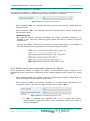
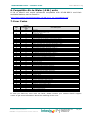
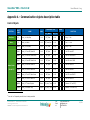
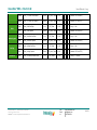
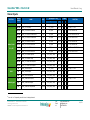
® IntesisBox HI-AW-KNX-1 User’s Manual Issue date: 09/01/2013 r1 eng IntesisBox® KNX – Hitachi A.W. User’s Manual r1 eng © Intesis Software S.L. 2012 All Rights Reserved. Information in this document is subject to change without prior notice. The software described in this document is furnished under a license agreement or nondisclosure agreement. The software may be used only in accordance with the terms of those agreements. No part of this publication may be reproduced, stored in a retrieval system or transmitted in any form or any means electronic or mechanical, including photocopying and recording for any purpose other than the purchaser’s personal use without the written permission of Intesis Software S.L. Intesis Software S.L. Milà i Fontanals, 1 bis 08700 Igualada Spain TRADEMARKS All trademarks and trade names used in this document are acknowledged to be the copyright of their respective holders. Information in this document is subject to changes without prior notice. © Intesis Software S.L. - All rights reserved This information is subject to change without notice ® IntesisBox is a registered trademark of Intesis Software SL URL Email tel http://www.intesis.com [email protected] +34 938047134 2 / 21 IntesisBox® KNX – Hitachi A.W. User’s Manual r1 eng Interface for the integration of Hitachi’s Air-toWater units into KNX TP-1 (EIB) control systems. Compatible with Air-to-Water Yutaki S series. Application’s Program Version: 0.2 Reference: HI-AW-KNX-1 © Intesis Software S.L. - All rights reserved This information is subject to change without notice ® IntesisBox is a registered trademark of Intesis Software SL URL Email tel http://www.intesis.com [email protected] +34 938047134 3 / 21 IntesisBox® KNX – Hitachi A.W. User’s Manual r1 eng INDEX 1. Presentation ......................................................................................................... 5 2. Connection ........................................................................................................... 6 3. Installation and setup ............................................................................................ 6 4. ETS parameters and communication objects ............................................................. 7 4.1 Default settings ................................................................................................. 7 Run or Stop the unit..................................................................................... 7 Change de Unit mode ................................................................................... 7 Run or Stop the C1 Circuit ............................................................................ 7 Anti-legionella System .................................................................................. 8 KNX menu blocking ...................................................................................... 8 Errors and Alarms ........................................................................................ 8 4.2 General dialog ................................................................................................... 9 4.2.1 System working mode .................................................................................. 9 OTC Mode ................................................................................................... 9 Water mode temperatures .......................................................................... 10 Air mode temperatures ............................................................................... 10 4.2.2 2nd circuit (C2) is available ......................................................................... 11 4.2.3 DHW is available (Domestic Hot Water) ........................................................ 12 Domestic Hot Water ................................................................................... 12 4.2.4 Swimming pool is available ......................................................................... 13 Swimming pool .......................................................................................... 13 4.2.5 Enable use of extra information objects (for Status) ....................................... 13 Yutaki S Extra Information .......................................................................... 14 Yutaki S80 Extra Information ...................................................................... 14 5. Technical Specifications ........................................................................................ 15 6. Compatible Air-to-Water (A.W.) units ..................................................................... 16 7. Error Codes ........................................................................................................ 16 Appendix A – Communication objects description table ................................................ 17 © Intesis Software S.L. - All rights reserved This information is subject to change without notice ® IntesisBox is a registered trademark of Intesis Software SL URL Email tel http://www.intesis.com [email protected] +34 938047134 4 / 21 IntesisBox® KNX – Hitachi A.W. User’s Manual r1 eng 1. Presentation The HI-AW-KNX-1 gateways allows fully bidirectional monitoring and control of the Hitachi Air-to-Water systems from KNX installations. The interface is compatible with all the models of the Yutaki S line commercialized by Hitachi. General features: Reduced dimensions, easy and fast installation. Multiple control and status objects (bit, byte, characters…) with standard KNX datapoints. One status object available for each control object. Control on the A.W. unit based on the ambient temperature read from the unit itself or from the temperature read by any KNX thermostat. The Hitachi A.W. can be controlled simultaneously through the remote controller of the A.W. system or through the KNX bus. Total supervision and control of the Hitachi A.W. unit from KNX, including unit internal variables supervision, special modes control (such as Anti-legionella) and error alarm and codes too. © Intesis Software S.L. - All rights reserved This information is subject to change without notice ® IntesisBox is a registered trademark of Intesis Software SL URL Email tel http://www.intesis.com [email protected] +34 938047134 5 / 21 IntesisBox® KNX – Hitachi A.W. User’s Manual r1 eng 2. Connection Connection of the interface to the AW indoor unit is by means of the cable supplied with the indoor unit to connect the remote controller. It must be connected to the interface in one side (connector H-Link) and to the internal electronic board of the Air-to-Water indoor unit in the other side. Connection of the interface to the KNX bus is by means of the standard KNX bus connector also supplied with the interface. In order to plug the interface to the external power supply, two different methods are available. First one is using the external power supply provided with the interface using the DC JACK connector Connections diagram: Power Supply A KNX TP-1 (Bus EIB) 2 wire terminal B B DC Jack IMPORTANT Connect only one external power supply. Use either the two-wire terminal connector (A) or the DC adaptor Jack connector (B). H-Link HI-AW-KNX-1 Max 1000 m Hitachi - Yutaki 3. Installation and setup This is a fully compatible KNX device that must be configured using the ETS software. The ETS database can be downloaded from: http://www.intesis.com/down/eib/HI-AW-KNX-1.zip Please, check the README.txt file located inside the zip file to find instructions for proper installation of the database. IMPORTANT: Do not forget to select the corresponding features of the Air-to-Water system connected to the HI-AW-KNX-1 interface. This should be selected in the “Parameters” section on the ETS software. © Intesis Software S.L. - All rights reserved This information is subject to change without notice ® IntesisBox is a registered trademark of Intesis Software SL URL Email tel http://www.intesis.com [email protected] +34 938047134 6 / 21 IntesisBox® KNX – Hitachi A.W. User’s Manual r1 eng 4. ETS parameters and communication objects 4.1 Default settings When importing the ETS database for the first time, the following menu appears, with these parameter values selected as default: Figure 4.1 Parameter values by default With this configuration is possible to control the system (Control_ objects) and monitoring it (Status_ objects) through the following communication objects: Run or Stop the unit Figure 4.2 Run/Stop communication objects This object allows to run or to stop the Hitachi unit features (C1,C2, DHW and/or SwimPool) at once. Sending a “0” value will turn them off, while sending a “1” value will turn them on. Change de Unit mode Figure 4.3 Unit mode selection communication objects This object allows changing the working mode of the Hitachi unit. Sending a “0” value the unit will turn into “Cool” mode, while sending a “1” value will make the unit turn into “Heat” mode. Run or Stop the C1 Circuit Figure 4.4 C1 circuit Run/Stop communication objects This object allows to run or to stop the Hitachi C1 Circuit (or C1 climate zone). Sending a “0” value will close the C1 circuit, while sending a “1” value will open the C1 Circuit. More functions related with the C1 circuit and their communication objects can be seen in section 4.2.1. © Intesis Software S.L. - All rights reserved This information is subject to change without notice ® IntesisBox is a registered trademark of Intesis Software SL URL Email tel http://www.intesis.com [email protected] +34 938047134 7 / 21 IntesisBox® KNX – Hitachi A.W. User’s Manual r1 eng Anti-legionella System NOTE: The anti-legionella function is hidden to users by default. Installer can make it available if desired. Figure 4.5 Anti-legionella sysmte communication objects The Hitachi Yutaki S units include an Anti-legionella system. From the gateway, this function can be activated by sending a “1” value to the Control_ AntiLeg Run/Stop object and can be stopped by sending a “0” value to the same object. It is also possible to send a value to set the temperature of the Anti-legionella system to this value. To do it so you have to use the Control_ AntiLeg Setpoint object. IMPORTANT: Anti-legionella will set the water temperature to the setting value during the specified time. This temperature will be dangerous to the user and could burn him or her. Installer is responsible for configuring it properly, advising the user, and enabling the function. KNX menu blocking Figure 4.6 KNX menu communication objects This object allows blocking or enabling the KNX menu from Hitachi’s LCD panel. Sending a “0” value will block the Menu, while sending a “1” value will enable the Menu. Errors and Alarms Figure 4.7 Errors and alarms communication objects These objects allows reading the system status indicating if any alarm or error is active (Status_ Error/Alarm) and, in case it exist, it indicates which error is (Status_ Error Code). See section 7 to get more information about the error codes. © Intesis Software S.L. - All rights reserved This information is subject to change without notice ® IntesisBox is a registered trademark of Intesis Software SL URL Email tel http://www.intesis.com [email protected] +34 938047134 8 / 21 IntesisBox® KNX – Hitachi A.W. User’s Manual r1 eng 4.2 General dialog In the General Dialog (settings) tab, it is possible to enable, disable or modify the parameters shown in Figure 4.1. For instance, the first field is showing where you can download the database and the user manual from. Figure 4.8 Database and User Manual location 4.2.1 System working mode This parameter enables or disables communication objects depending on the working mode selected: Water mode, Air, mode or Full (which includes both: Water and Air). Figure 4.9 System working mode parameter details o When selecting “Water” the interface will work for a water climate environment only. Water climate control and status objects will be available. Air climate control and status objects will be disabled. OTC Mode The OTC mode (Output Temperature Compensation) allows keeping the desired indoor temperature despite external temperature variations. From the gateway you can: Turn this function off by sending a “1” value to the Control_ C1 OTC Mode Heat/Cool Off communication object. Figure 4.10 OTC Mode Off communication objects Activate the different modes available for the calculus of the water temperature for the cooling or heating the facility where the unit is placed: Points: User fixes 4 points that will create a line function that will depend on the current ambient temperature. Gradients: In this case, the function used is not a line but a gradient. Only available for the Heat mode. Fix: The temperature adjustment is only performed by a fixed value. This makes the unit to keep this fixed value all the time. © Intesis Software S.L. - All rights reserved This information is subject to change without notice ® IntesisBox is a registered trademark of Intesis Software SL URL Email tel http://www.intesis.com [email protected] +34 938047134 9 / 21 IntesisBox® KNX – Hitachi A.W. User’s Manual r1 eng Figure 4.11 OTC Mode type selection communication objects Water mode temperatures Using the following communication objects it is possible to control/monitorize water setpoint temperatures for the Heat and Cool modes (C1 Water Heat Setpoint and C1 Water Cool Setpoint). Figure 4.12 Water Mode temperatures communication objects o When selecting “Air”, the interface will work for an air climate environment only. Air climate control and status objects will be available. Water climate control and status objects will be disabled. Air mode temperatures With the communication objects corresponding to this mode enabled, control/monitoring of the setpoint temperature of the thermo (C1 Thermo Setpoint) and the ambient temperature provided by a thermostat not included in the Hitachi system (C1 Ambient Temp). Figure 4.13 Air mode temperature communication objects o When selecting “Full”, the interface will work for an air and water climate environment. Air and Water climate control and status objects will be available. © Intesis Software S.L. - All rights reserved This information is subject to change without notice ® IntesisBox is a registered trademark of Intesis Software SL URL Email tel http://www.intesis.com [email protected] +34 938047134 10 / 21 IntesisBox® KNX – Hitachi A.W. User’s Manual r1 eng 4.2.2 2nd circuit (C2) is available This parameter enables or disables the Control_ and Status_ communication objects of a second circuit (or climate zone). In case the project is divided into 2 separated circuits this parameter needs to be selected to get control on each circuit independently. Figure 4.14 2nd circuit parameter detail o When selecting “No”, the gateway will hide the 2nd circuit (C2) communication objects. o When selecting “Yes”, the gateway will show the the 2nd circuit (C2) communication objects. Depending on the other selected parameters, some objects will remain hidden and some others will be shown. Run and Stop status: Figure 4.15 2nd circuit Run/Stop communication objects To activate or deactivat the 2nd circuit (C2) a “1” value or a “0” value needs to be sent respectively to the Run/stop communication object. If “Water” mode is selected: Figure 4.16 2nd circuit Water Mode communication objects © Intesis Software S.L. - All rights reserved This information is subject to change without notice ® IntesisBox is a registered trademark of Intesis Software SL URL Email tel http://www.intesis.com [email protected] +34 938047134 11 / 21 IntesisBox® KNX – Hitachi A.W. User’s Manual r1 eng If “Air” mode is selected: Figure 4.17 2nd circuit Air Mode communication objects If “Full” mode is selected, all communication objects present when selecting “Water” or “Air” will be enabled for this mode too. 4.2.3 DHW is available (Domestic Hot Water) This parameter enables or disables the Control_ and Status_ objects corresponding to the control and monitoring of a water tank or DHW system. Figure 4.18 DHW Parameter detail o When selecting “No”, the gateway will hide communication objects related with the water tank or the Domestic Hot Water system. o When selecting “Yes”, the gateway will show the communication objects related with the water tank or the Domestic Hot Water system. Domestic Hot Water By means of Control_ DHW Run/Stop and Control_ DHW Setpoint, it is possible to turn on/off the DHW system and also to control its setpoint temperature. Through the Status_ DHW Temperature communication object, it is possible to read the instantaneous temperature of the DHW system. Figure 4.19 DHW mode communication objects © Intesis Software S.L. - All rights reserved This information is subject to change without notice ® IntesisBox is a registered trademark of Intesis Software SL URL Email tel http://www.intesis.com [email protected] +34 938047134 12 / 21 IntesisBox® KNX – Hitachi A.W. User’s Manual r1 eng 4.2.4 Swimming pool is available This parameter enables or disables the Control_ and Status_ objects corresponding to the control and monitoring of a swimming pool system present in the project Figure 4.20 Swimming pool parameter details o When selecting “No”, the gateway will hide communication objects related with the swimming pool. o When selecting “Yes”, the gateway will show communication objects related with the swimming pool. Swimming pool By means of Control_ SwimPool Run/Stop and Control_ SwimPool Setpoint, it is possible to turn on/off the Swimming pool system and also to control its setpoint temperature. Through the Status_ SwimPool Temperature communication object, it is possible to read the instantaneous temperature of the Swimming pool system. Figure 4.21 Swimming pool mode communication objects 4.2.5 Enable use of extra information objects (for Status) These parameters enable or disable the Status_ communication objects related to the monitoring of extra information depending on the installed Hitachi model (Yutaki S or Yutaki S80). o When selecting “No”, the gateway will hide communication objects related with the extra information provided by the Hitachi units. o When selecting “Yes”, the gateway will offer you to select extra information for a Yutaki S80 model or the rest of Yutaki S models (then select “No”). Figure 4.22 Extra Information parameters detail If “No” is selected (the installed unit is not a Yutaki S80 model) communication objects providing extra information about the Yutaki S models will appear. © Intesis Software S.L. - All rights reserved This information is subject to change without notice ® IntesisBox is a registered trademark of Intesis Software SL URL Email tel http://www.intesis.com [email protected] +34 938047134 13 / 21 IntesisBox® KNX – Hitachi A.W. User’s Manual r1 eng Yutaki S Extra Information Figure 4.23 Extra Information status communication objects If “Yes” is selected (the installed unit is a Yutaki S80 model), the Control_ Unit Mode and the Status_ Unit Mode communication objetcs will be hidden and new communication objects will appear providing extra and specific information for the Yutaki S80. Yutaki S80 Extra Information Figure 4.24 Extra Information for Yutaki S80 status communication objects For more details about the information provided by those comunication objects, please check the Hitachi user manual. © Intesis Software S.L. - All rights reserved This information is subject to change without notice ® IntesisBox is a registered trademark of Intesis Software SL URL Email tel http://www.intesis.com [email protected] +34 938047134 14 / 21 IntesisBox® KNX – Hitachi A.W. 5. User’s Manual r1 eng Technical Specifications Enclosure Dimensions Weight Color Power supply ABS (UL 94 HB) de 2,5 mm thick 70 X 70 X 28 mm 70g Ivory White 29V DC, 6mA (KNX bus) 10-40V DC, 100mA (Recommended: 12V DC, 100 mA) External Power Supply Terminal wiring (for power supply and low-voltage signals) KNX port H-Link port LED indicators Push buttons Configuration Operating Temperature Storage Temperature Operating Humidity Isolation voltage RoHS conformity Certifications Must use a NEC Class 2 or Limited Power Source (LPS) and SELV rated power supply. Plug-in terminal block for power connection (2 poles). Per terminal: solid wires or stranded wires (twisted or with ferrule) 1 core: 0.5mm2… 2.5mm2 2 cores: 0.5mm2… 1.5mm2 3 cores: not permitted 1 x KNX TP1 (EIB) port opto-isolated. Plug-in terminal block (2 poles). TNV-1 Plug-in terminal block for H-Link bus connection (2 poles) with no polarity 1 x KNX programming. 1 x KNX programming. Configuration with ETS. From 0ºC to 40ºC From 0ºC to 40ºC 25-90% at 50ºC, non condensing External Power Supply – KNX: 2500V External Power Supply – H-Link: 1500V Compliant with RoHS directive (2002/95/CE). CE conformity to EMC directive (2004/108/EC) and Low-voltage directive (2006/95/EC) EN 61000-6-2; EN 61000-6-3; EN 60950-1; EN 50491-3; EN 50090-2-2; EN 50428; EN 60669-1; EN 60669-2-1 External Power Supply connection KNX port KNX programming LED KNX programming button 70 mm H-Link port 70 mm © Intesis Software S.L. - All rights reserved This information is subject to change without notice ® IntesisBox is a registered trademark of Intesis Software SL 28 mm URL Email tel http://www.intesis.com [email protected] +34 938047134 15 / 21 IntesisBox® KNX – Hitachi A.W. User’s Manual r1 eng 6. Compatible Air-to-Water (A.W.) units A list of Hitachi unit model references compatible with HI-AW-KNX-1 and their available features can be found in: http://www.intesis.com/pdf/IntesisBox_HI-AW-xxx-1_AC_Compatibility.pdf 7. Error Codes 00 Remote Controller Error Code N/A 02 02 03 04 05 06 07 08 11 12 13 14 15 16 17 18 20 21 22 24 31 35 38 41 42 47 48 51 53 54 55 59 b1 EE 70 71 72 73 74 75 76 77 78 79 80 81 65535 03 04 05 06 07 08 11 12 13 14 15 16 17 18 20 21 22 24 31 35 38 41 42 47 48 51 53 54 55 59 b1 EE 70 71 72 73 74 75 76 77 78 79 80 81 N/A KNX Error Code Error Description No errors Activation of Outdoor Unit Protection Device (Except for Alarm Code 41, 42) Transmission Error Inverter Transmission Abnormality Power Phase Detection Abnormality Undervoltage, Overvoltage Abnormal decrease of discharge gas superheat degree Compressor-Top Temp Over-increase Water inlet thermistor abnormally (THMWI) Water outlet thermistor abnormally (THMWO) Indoor Liquid Pipe Temp Thermistor Abnormality (THML) Indoor Gas Pipe Temp. Thermistor Abnormality (THMG) Water outlet C2 thermistor abnormally (THMWO2) Water DHWT thermistor abnormally (THMDHWT) Swimming pool thermistor abnormally (THMSWP) Water outlet boiler thermistor abnormally (THMWO3) Compressor-Top Temp Thermistor Abnormality 2nd ambient thermistor abnormally (THMAMB2) Outdoor Temp Thermistor Abnormality Outdoor Heat Exchanger Liquid Pipe Thermistor Abnormality Indoor/Outdoor Combination Setting Error Indoor Unit Number Setting Error Outdoor Protection Detection Circuit Abnormality Cooling Overload Heating Overload Suction Pressure Decrease Prevention Activated Inverter Current Sensor Abnormality Overload Operation Protection Activation Inverter Module Error Inverter Fin Temp. Abnormality Inverter Non-Operation Inverter Fin Temp Thermistor Abnormality Error in Address/Refrigerant System Setting Compressor Factor Alarm Hydraulic alarm Water Pump Feedback Thermostat Heater Alarm Mixing over-temperature limit protection for Mixed circuit Unit over-temperature limit protection Freeze Protection by Cold water inlet, outlet temperature detection Freeze Protection Stop by indoor liquid temperature thermistor Opentherm Communication failure RF Communication failure Unit Capacity setting Error LCD H-link transmission error Incorrect PCB operation Communication error between HI-AW-KNX-1 interface and the Hitachi Unit In case you detect an error code not listed, please contact your nearest Hitachi support center to get more information about the meaning of the error. © Intesis Software S.L. - All rights reserved This information is subject to change without notice ® IntesisBox is a registered trademark of Intesis Software SL URL Email tel http://www.intesis.com [email protected] +34 938047134 16 / 21 IntesisBox® KNX – Hitachi A.W. User’s Manual r1 eng Appendix A – Communication objects description table Control Objects SECTION 1 OBJECT NUMBER NAME LONG. DATAPOINT TYPE FLAGS DPT_NAME DPT_ID R W T FUNCTION U Run/Stop 0 Control_ Unit Run/Stop 1 bit DPT_Start 1.010 W T 0 - Stop; 1 - Run Mode 1 Control_ Unit Mode 1 bit DPT_Heat/Cool 1.100 W T 0 - Cool; 1 – Heat 2/14 Control_ Cx1 Run/Stop 1 bit DPT_Start 1.010 W T 0 - Stop; 1 - Run 3/15 Control_ Cx1 Heat OTC Mode Off 1 bit DPT_Bool 1.002 W T 1 – Set OTC Mode OFF 4/16 Control_ Cx1 Heat OTC Mode Points 1 bit DPT_Bool 1.002 W T 1 – Set OTC Mode POINTS 5/17 Control_ Cx1 Heat OTC Mode Grad 1 bit DPT_Bool 1.002 W T 1 – Set OTC Mode GRAD Water Circuit 6/18 Control_ Cx1 Heat OTC Mode Fix 1 bit DPT_Bool 1.002 W T 1 – Set OTC Mode FIX (C1 and C2) 7/19 Control_ Cx1 Cool OTC Mode Off 1 bit DPT_Bool 1.002 W T 1 – Set OTC Mode OFF 8/20 Control_ Cx1 Cool OTC Mode Points 1 bit DPT_Bool 1.002 W T 1 – Set OTC Mode POINTS 9/21 Control_ Cx1 Cool OTC Mode Fix 1 bit DPT_Bool 1.002 W T 1 – Set OTC Mode FIX 10/22 Control_ Cx1 Thermo Setpoint 2 bytes DPT_Value_Temp 9.001 W T ºC (Between 0ºC and 35ºC) 11/23 Control_ Cx1 Ambient Temp 2 bytes DPT_Value_Temp 9.001 W T ºC (Between -20ºC and 40ºC) X can be 1 or 2 depending on which circuit is being controlled. © Intesis Software S.L. – Todos los derechos reservados Información sujeta a cambios sin previo aviso IntesisBox® es una marca registrada de Intesis Software SL URL Email tel http://www.intesis.com [email protected] +34 938047134 17 / 21 IntesisBox® KNX – Hitachi A.W. User’s Manual r1 eng 12/24 Control_ Cx1 Water Heat Setpoint 2 bytes DPT_Value_Temp 9.001 W T ºC (Between 20ºC and 80ºC) 13/25 Control_ Cx1 Water Cool Setpoint 2 bytes DPT_Value_Temp 9.001 W T ºC (Between 5ºC and 21ºC) 26 Control_ DHW Run/Stop 1 bit DPT_Start 1.010 W T 0 - Stop; 1 - Run 27 Control_ DHW Setpoint 2 bytes DPT_Value_Temp 9.001 W T ºC (Between 30ºC and 75ºC) 28 Control_ SwimPool Run/Stop 1 bit DPT_Start 1.010 W T 0 - Stop; 1 - Run 29 Control_ SwimPool Setpoint 2 bytes DPT_Value_Temp 9.001 W T ºC (Between 24ºC and 33ºC) 30 Control_ AntiLeg Run/Stop 1 bit DPT_Start 1.010 W T 0 - Stop; 1 - Run 31 Control_ AntiLeg Setpoint 2 bytes DPT_Value_Temp 9.001 W T ºC (Between 50ºC and 75ºC) 32 Control_ KNX Blocks/Enables Menu 1 bit DPT_Enable 1.003 W T 0 – Blocks; 1 – Enables DHW Swimming pool AntiLeg KNX Block © Intesis Software S.L. – Todos los derechos reservados Información sujeta a cambios sin previo aviso IntesisBox® es una marca registrada de Intesis Software SL URL Email tel http://www.intesis.com [email protected] +34 938047134 18 / 21 IntesisBox® KNX – Hitachi A.W. User’s Manual r1 eng Status Objects SECTION OBJETO NUMBER Mode 33 34/46 35/47 Water Circuit (C1 y C2) Swimming pool 2 LONG. DATAPOINT TYPE DPT_NAME FLAGS DPT_ID R W T FUNCTION U Status_ Unit Mode 1 bit DPT_Heat/Cool 1.100 R T 0 – Cool; 1 – Heat Status_ Cx2 Run/Stop 1 bit DPT_Start 1.010 R T 0 – Stop; 1 – Run 2 1 bit DPT_Bool 1.002 R T 1 – OTC Mode Off Set 2 Status_ Cx Heat OTC Mode Off 36/48 Status_ Cx Heat OTC Mode Points 1 bit DPT_Bool 1.002 R T 1 – OTC Mode POINTS Set 37/49 Status_ Cx2 Heat OTC Mode Grad 1 bit DPT_Bool 1.002 R T 1 – OTC Mode FIX Set 38/50 Status_ Cx2 Heat OTC Mode Fix 39/51 1 bit DPT_Bool 1.002 R T 1 – OTC Mode Off Set 2 1 bit DPT_Bool 1.002 R T 1 – OTC Mode Off Set 2 Status_ Cx Cool OTC Mode Off 40/52 Status_ Cx Cool OTC Mode Points 1 bit DPT_Bool 1.002 R T 1 – OTC Mode POINTS Set 41/53 Status_ Cx2 Cool OTC Mode Fix 1 bit DPT_Bool 1.002 R T 1 – OTC Mode FIX Set 42/54 Status_ Cx2 Thermo Setpoint 43/55 DHW NAME 2 bytes DPT_Value_Temp 9.001 R T ºC 2 2 bytes DPT_Value_Temp 9.001 R T ºC 2 Status_ Cx Ambient Temp 44/56 Status_ Cx Water Heat Setpoint 2 bytes DPT_Value_Temp 9.001 R T ºC 45/57 Status_ Cx2 Water Cool Setpoint 2 bytes DPT_Value_Temp 9.001 R T ºC 58 Status_ DHW Run/Stop 1 bit DPT_Start 1.010 R T 0 – Stop; 1 – Run 59 Status_ DHW Setpoint 2 bytes DPT_Value_Temp 9.001 R T ºC 60 Status_ DHW Temperature 2 bytes DPT_Value_Temp 9.001 R T ºC 61 Status_ SwimPool Run/Stop 1 bit DPT_Start 1.010 R T 0 – Stop; 1 – Run 62 Status_ SwimPool Setpoint 2 bytes DPT_Value_Temp 9.001 R T ºC 63 Status_ SwimPool Temperature 2 bytes DPT_Value_Temp 9.001 R T ºC X can be 1 or 2 depending on which circuit is being observed. © Intesis Software S.L. – Todos los derechos reservados Información sujeta a cambios sin previo aviso IntesisBox® es una marca registrada de Intesis Software SL URL Email tel http://www.intesis.com [email protected] +34 938047134 19 / 21 IntesisBox® KNX – Hitachi A.W. AntiLeg KNX Block Error and Alarms Extra Information User’s Manual r1 eng 64 Status_ AntiLeg Run/Stop 1 bit DPT_Start 1.010 R T 0 – Stop; 1 – Run 65 Status_ AntiLeg Setpoint 2 bytes DPT_Value_Temp 9.001 R T ºC 66 Status_ KNX Block/Enable Menu 1 bit DPT_Enable 1.003 R T 0 – Block; 1 – Enable 67 Status_ Error/Alarm 1 bit DTP_Alarm 1.005 R T 0 - No Alarm; 1 - Alarm 68 Status_ Error Code 2 bytes R T 0 – No error; Other values see 7 69 Status_ Operation State Unit On/Off 1 bit DPT_Switch 1.001 R T 0 - Off; 1-On 70 Status_ Operation State Cool Demand 1 bit DPT_Switch 1.001 R T 0 - Off; 1-On 71 Status_ Operation State Cool Thermo 1 bit DPT_Switch 1.001 R T 0 - Off; 1-On 72 Status_ Operation State Heat Demand 1 bit DPT_Switch 1.001 R T 0 - Off; 1-On 73 Status_ Operation State Heat Thermo 1 bit DPT_Switch 1.001 R T 0 - Off; 1-On 74 Status_ Operation State DHW 1 bit DPT_Switch 1.001 R T 0 - Off; 1-On 75 Status_ Operation State Swim Pool 1 bit DPT_Switch 1.001 R T 0 - Off; 1-On 76 Status_ Operation State Alarm 1 bit DTP_Alarm 1.005 R T 0 - No Alarm; 1 - Alarm 77 Status_ Outdoor Ambient Temp 2 bytes DPT_Value_Temp 9.001 R T ºC 78 Status_ Second Ambient Temp 2 bytes DPT_Value_Temp 9.001 R T ºC 79 Status_ Water Inlet Temp 2 bytes DPT_Value_Temp 9.001 R T ºC 80 Status_ Water Outlet Temp 2 bytes DPT_Value_Temp 9.001 R T ºC 81 Status_ Defrost Operation 1 bit DPT_Switch 1.001 R T 0 - Off; 1-On 82 Status_ Water Pump 1 Operation 1 bit DPT_Switch 1.001 R T 0 - Off; 1-On 83 Status_ Water Pump 2 Operation 1 bit DPT_Switch 1.001 R T 0 - Off; 1-On 84 Status_ Water Pump 3 Operation 1 bit DPT_Switch 1.001 R T 0 - Off; 1-On 85 Status_ Dish. Gas Temp 2 bytes DPT_Value_Temp 9.001 R T ºC 86 Status_ Suct. Gas Temp 2 bytes DPT_Value_Temp 9.001 R T ºC © Intesis Software S.L. – Todos los derechos reservados Información sujeta a cambios sin previo aviso IntesisBox® es una marca registrada de Intesis Software SL Enumerated URL Email tel http://www.intesis.com [email protected] +34 938047134 20 / 21 IntesisBox® KNX – Hitachi A.W. Extra Information Yutaki S80 User’s Manual r1 eng 87 Status_ Gas Temp THMg 2 bytes DPT_Value_Temp 9.001 R T ºC 88 Status_ Liquid Temp THMI 2 bytes DPT_Value_Temp 9.001 R T ºC 89 Status_ Water Outlet Temp 3 2 bytes DPT_Value_Temp 9.001 R T ºC 90 Status_ Outdoor AmbAvg Temp 2 bytes DPT_Value_Temp 9.001 R T ºC 91 Status_ Inv Oper Freq 2 bytes DPT_Value_Frequency 14.033 R T Hz 92 Status_ Indoor Exp Valve Opening 1 byte DPT_Scaling 5.001 R T % 93 Status_ Outdoor Exp Valve Opening 1 byte DPT_Scaling 5.001 R T % 94 Status_ Mixing Valve Position 1 byte DPT_Scaling 5.001 R T % 95 Status_ Compressor Run Current 2 bytes DPT_Value_Cur 9.021 R T mA 96 Status_ Dish. Gas Temp R134A 2 bytes DPT_Value_Temp 9.001 R T ºC 97 Status_ Suct. Gas Temp R134A 2 bytes DPT_Value_Temp 9.001 R T ºC 98 Status_ Liquid Temp R134A 2 bytes DPT_Value_Temp 9.001 R T ºC 99 Status_ Evap. Gas Temp R134A 2 bytes DPT_Value_Temp 9.001 R T ºC 100 Status_ Disch. Pressure R134A 2 bytes DPT_Value_Pressure 14.058 R T Pa 101 Status_ Suct. Pressure R134A 2 bytes DPT_Value_Pressure 14.058 R T Pa 102 Status_ Inv Oper Freq R134A 2 bytes DPT_Value_Frequency 14.033 R T HZ 103 Status_ Indoor Exp Valve Open R134A 1 byte DPT_Scaling 5.001 R T % 104 Status_ Compressor Run Current R134A 2 bytes DPT_Value_Cur 9.021 R T A 105 Status_ Error Code R134A 2 bytes R T 0 – No error; Other values see 7 © Intesis Software S.L. – Todos los derechos reservados Información sujeta a cambios sin previo aviso IntesisBox® es una marca registrada de Intesis Software SL Enumerated URL Email tel http://www.intesis.com [email protected] +34 938047134 21 / 21