1
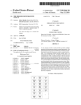
US006657548B2
(12) United States Patent
Dai
(54)
(10) Patent N0.:
US 6,657,548 B2
(45) Date of Patent:
Dec. 2, 2003
sYsTEM sTATUs LIGHT INDICATOR
6,501,897 B1 * 12/2002 German 6161. ........... .. 385/134
DEVICE EMBEDDED INA CONNECTING
6,503,105 B1 *
1/2003 161mm .................... .. 439/668
PORT
* cited by examiner
(75) Inventor: Ming-Hou Dai, Taoyuan
(73) Assignee: Asustek Computer Inc., Taipei (TW)
(*)
Notice:
Subject to any disclaimer, the term of this
patent is extended or adjusted under 35
U.S.C. 154(b) by 252 days.
Prior Publication Data
the BIOS examines a plurality of the peripheral devices on
Foreign Application Priority Data
May 11, 2000
(51)
(52)
(58)
(TW) .................................... .. 89207905 U
Int. Cl.7 ............................ .. G08B 5/22; G09F 9/33
US. Cl. ................. .. 340/815.45; 439/490; 361/788
Field of Search ....................... .. 340/815.45, 815.4,
340/81542, 815.52, 693.5, 815.49; 439/488,
490, 917; 361/601, 686, 788
(56)
ABSTRACT
a plurality of light emitting diodes (LED), suitable for use
With a Basic Input-Output System (BIOS) program. When
US 2002/0032885 A1 Mar. 14, 2002
(30)
(57)
A system status light indicator device embedded in a con
necting port is made up of an error message processor and
(21) Appl. No.: 09/852,005
(22) Filed:
May 10, 2001
(65)
Primary Examiner—Toan N Pham
(74) Attorney, Agent, or Firm—Rabin & Berdo, PC.
the computer, as soon as an error is found, the Warning
signals can be sent to the error message processor, and then
the corresponding error message data is retrieved. Next, it
outputs the error message data to the system status indicator
devices embedded in a connecting port. Thus, the operators
can knoW exactly Where the problems are located via the
indicated boot-up Warning signals sent out that indicate
system status, and the messages corresponding to the light
indicators recorded in the user’s manual. The above
described error message data uses the light indicators to
References Cited
display the various causes of breakdown.
U.S. PATENT DOCUMENTS
5,685,741 A
ELF-Tin“
* 11/1997 Dewey et a1. ............ .. 439/668
13 Claims, 3 Drawing Sheets
16a
Error
I
Message
I
Processor ‘
16b
16c
16d
11
12
" 200(300)
U.S. Patent
Dec. 2, 2003
Sheet 1 of3
FIG.1
US 6,657,548 B2
U.S. Patent
Dec. 2, 2003
Sheet 2 of3
US 6,657,548 B2
Junction
' ’\d-- 2 l a
Junction
"\?- 21b
20
FIG.2A
16b
16d
16a1 I
16c l
\\
l
\\]unctioy 1x»- 2013
208 A?
b ‘0 or (B
7
Junction
FIG.2B
M205
T'MPI 20w
U.S. Patent
Dec. 2, 2003
Sheet 3 of3
\
Junction
US 6,657,548 B2
A
’\/ 35
\— 31
5g
FIG.3A
16a
16b
16c
16d
308A9 o
a;
jg
o
\
Junction
“V305
A
2)..
FIG.3B
g 301
US 6,657,548 B2
1
2
SYSTEM STATUS LIGHT INDICATOR
DEVICE EMBEDDED IN A CONNECTING
PORT
TABLE I-continued
Boot-up Warnings for the BIOS of IBM
Beep
CROSS-REFERENCE TO RELATED
APPLICATION
Meaning
Two short
Error found during self-test and it is displayed
on the monitor
This application claims the priority bene?t of Taiwan
application serial no. 89207905, ?led on May 11, 2000.
Errors on the motherboard
Errors on the display
One long and three short Errors on the EGA card
Three long
Errors on the keyboard controller
BACKGROUND OF THE INVENTION
1. Field of the Invention
The present invention relates to a system status light
indicator device embedded in a connecting port. More
particularly, the present invention relates to a system status
Power supply and motherboard breakdown
Continuous short
One long and one short
10 One long and two short
TABLE II
15
Boot-up Warnings for the BIOS of AWARD
light indicator device embedded in a connecting port which
can clearly indicate to users the causes of breakdowns via
the warning light indicators during the booting-up process.
2. Description of Related Art
When we turn on the power of a personal computer, the
Beep
Meaning
One short
One long and two short
Two short
Not an error, indicates system turn-on
Errors on the EGA card
There are errors and is indicated on the monitor
One long and three short Errors on the keyboard controller
central processing unit (CPU) inside the PC may start
eXecuting a series of commands; the commands can be
approximately divided into three categories according to the
25
TABLE III
functions:
1. System Con?guration Analysis (SCA) analyZes the
Boot-up Warnings for the BIOS of AMI
CPU type, the siZe of memory, the number and types of
?oppy and hard disks, yes or no to install the ?oating
Beep
processor as an important reference for the other
actions.
2. The Power On Self Test (POST) program tests the
status of hardware such as the memory, chipsets,
CMOS, stored data, keyboard and disk drives; once an
error is found, it will report the problems.
Meaning
1
2
Defects on the memory regain chipset
Errors found while checking the ?rst 64K of memory
3
Defects on the ?rst 64K of memory and are
unreadable
4
5
35
6
Clock on the motherboard is out of order
CPU breakdown
keyboard controller breakdown, disabled to enter the
protected mode
3. The address allocation of the operating system (like the
MS-DOS, Windows 95/98) and loads it up via what is
called the “Bootstrap Loader” short program, passes
the control of the computer to the operating system and
of?cially ends the boot-up action.
The program organiZed by the above commands is called
7
8
9
10
Errors
Errors
Errors
Errors
on
on
on
on
the
the
the
the
abnormal interrupt of CPU
read- write memory display region
checking value of ROM
read-write of CMOS shutoff register
11
Errors on the cache
From the tables above, we ?nd that the boot-up warnings
the Basic Input Output System (BIOS) program, therefore,
set by different PC vendors make use of long and short beep
the BIOS can be said as ?rst program eXecuted after the
personal computer is turned on. If it cannot run the BIOS 45 combinations to indicate problems that arise during the
booting-up process to users. However, since the speci?ca
program normally while in the process of booting-up the
computer, generally, the hardware can withstand certain
problems; the problems should ?rst be removed before
tions set by each vendor are not the same, and most users
would not remember the meanings of the different warning
signals; there is no point in having quick self-maintenance
for understanding the meanings of different boot warnings in
the internal process of computers.
continuing further operations, thereby ensuring that the
computer is running in the optimal mode.
However, in order not to infringe to the copyrights of the
BIOS originally made by IBM, the BIOS programs designed
by different vendors may process them with the same
function but different program codes, using the error mes
sage data in the above-described POST program procedure
as an eXample, the boot-up warnings of the BIOS programs
SUMMARY OF THE INVENTION
55
for use for a BIOS program; when the BIOS program detects
that errors have occurred on the peripheral devices of the
of three different vendors (IBM, AWARD, AMI), are de?ned
differently and listed in the tables below:
computer, it will send out a set of the warning signals.
The system status light indicator embedded in a connect
ing port comprises of an error message processor and a
TABLE I
plurality of light emitting diodes (LED). Firstly, the BIOS
Boot-up Warnings for the BIOS of IBM
Beep
Meaning
None
Power supply and CPU breakdown
Continuous
Short
Memory breakdown
System self-test, normal condition
Accordingly, the present invention is to provide a system
status light indicator embedded in a connecting port suitable
program starts checking the peripheral devices of the
computer, and as soon as the BIOS program detects errors,
65
it will send out a set of warning signals to the error message
processor, and retrieves the error message data previously
stored in the error message processor that correspond to the
warning signals. Thus, based on the light indications of the
US 6,657,548 B2
3
4
system boot-up warning status, the user can consult the
warning signal 11 via the controllable output port such as a
user’s manual in which the light indications corresponding
portion for input and startup 10 (as shown in FIG. 1) and
to the error signals are stated, and can know precisely where
the problem lies. The above-described error message indi
retrieve the error message data 15, which corresponds to the
warning signal and is stored inside the error message pro
cessor 12, followed by outputting the error message data 15
to the system status light indicators 16a~16d embedded in
cates the causes of the breakdowns via the error message
signal.
the port connectors 200 or 300. The user refers to the error
Since the causes of breakdowns have been recorded in the
error message processor, when the BIOS program detects
the peripheral device errors, the cause of breakdown can be
found by consulting the light indications corresponding to
message corresponding to the light indicators recorded in the
user’s manual to guide the user to locate precisely where the
10
the error signals recorded in the user’s manual. Thus, the
user knows exactly what the problem lies, and without
having to guess what a beep signi?es, or having to inspect
each device one by one. The direct use of a newly designed
universal serial bus (USB) connecting port and a printer
connecting port provides many embedded LED lights that
display the system status and which do not require de?ni
tions of special input/output shields.
It is to be understood that both the foregoing general
description and the following detailed description are
exemplary, and are intended to provide further explanation
15
problem is.
The above-described error message data uses the light
indicators 16a~16d to indicate the causes of breakdown, and
enables the user to easily understand what the computer
problem is, so that maintenance and further handling can be
facilitated.
FIG. 2A illustrates a conventional USB connecting port
20, in consideration of Electro-magnetic interference (EMI),
the computer motherboards used nowadays are all featuring
the I/O shield 25 in the input and output connecting ports.
The consideration of the present invention of a system status
light indicator device embedded in a connecting port lies in
not modifying the existing I/O shield 25, and in not in?u
of the invention as claimed.
encing the efficiency of the original connecting port, while
BRIEF DESCRIPTION OF THE DRAWINGS
25
The accompanying drawings are included to provide a
further understanding of the invention, and are incorporated
in and constitute a part of this speci?cation. The drawings
illustrate embodiments of the invention, and, together with
the description, serve to explain the principles of the inven
tion. In the drawings,
connecting port.
FIG. 2B illustrates the USB connecting port 200 in a
preferred embodiment featuring the system status light indi
FIG. 1 is a structural illustration of a system status light
indicator embedded in a connecting port, according to the
present invention;
FIG. 2A illustrates a conventional universal serial bus;
providing many LED signals that indicate system status. The
USB connecting port 20 includes one USB connecting port
I/O shield 25 and the two junctions 21a and 21b of the USB
35
FIG. 2B shows a serial bus connecting port featuring the
system status light indicator embedded in a connecting port;
FIG. 3A illustrates a conventional printer connecting port;
and
cator device embedded in a connecting port according to the
present invention. Since most of the I/O shield 205 within
the USB connecting port 200 is not located in the space 208
between the two junctions 201a and 201b of the USB
connecting port. The system status can be indicated through
the use of many LED light indicators 16a~16d embedded in
the space 208.
FIG. 3A illustrates a conventional printer connecting port,
wherein the printer connecting port 30 includes a printer
connecting port I/ O shield 35 and a junction 31 of the printer
connecting port.
FIG. 3B illustrates the printer connecting port featuring
the system status light indicator embedded in a connecting
FIG. 3B illustrates a printer connecting port 300 in a
preferred embodiment featuring system status light indica
port.
DESCRIPTION OF THE PREFERRED
EMBODIMENTS
tors embedded in a connecting port according to the present
45
FIG. 1 is a structural view of a system status light
indicator embedded in a connecting port. In FIG. 1, it can be
the system status light indicator device embedded in a
connecting port stays as near as possible to the I/O shield
seen that the present invention features a system structure
indicating the causes of breakdown, which includes the error
305 of the printer connecting port 300 in the present inven
tion. Consequently, the system status can be clearly indi
cated by identifying a plurality of the LED indicators
16a~16d, and meanwhile the electromagnetic radiation pro
message processor 12 and the system status light indicators
16a~16a'. The system status light indicators 16a~16d are
embedded into the newly-designed USB port 200 and printer
port 300. The existing status displaying system is not
modi?ed, and an I/O shield does not require special de?ni
invention. Since there is only a narrow space 308 between
the junction 301 of printer connecting port 300 and the I/O
shield 305, therefore, the preferred embodiment featuring
55
tection is not affected.
In summary of the above, it can be seen that the system
status light indicator device embedded in a connecting port
tion.
Now, let us continue describing the running procedures of
in the present invention, the conventional beep settings by
the system status light indicator embedded in a connecting
program itself. The BIOS program will use the POST
various vendors can be modi?ed into light signals. Thus
users can quickly locate the problems without having to
guess at the meaning of the beeps, or to perform checks on
the peripheral devices one by one.
program to check the hardware status of the peripheral
devices such as the memory, chipset, CMOS, stored data,
plary preferred embodiment. However, it is to be understood
port from the present invention. Firstly, when the computer
is turned on, the computer will proceed with the BIOS
The present invention has been disclosed using an exem
keyboard and hard drive. Once there are such errors as no
display on the monitor, shortage of electricity in the CMOS
battery, hard disk install failure, and keyboard error or no
keyboard present, the BIOS drive program will send out the
65
that the scope and the sprit of the invention is not limited to
the disclosed embodiments, on the contrary, it is intended to
cover various modi?cations and similar arrangements, the
scope of the claims, therefore, should be accorded the
US 6,657,548 B2
6
5
7. A connecting port device With embedded light
broadest interpretation so as to encompass all such modi?
cations and similar arrangements.
What is claimed is:
1. A system status light indicator device embedded in a
indicators, suitable for use on a computer system Which
includes at least one peripheral device, the computer having
a BIOS program that is used for checking the at least one
connecting port, suitable for use on a computer of a com
peripheral device and producing a Warning signal if an error
is found in the at least one peripheral device, the connecting
puter system Which includes a plurality of peripheral
devices, the computer having a BIOS program that is used
for checking the peripheral devices and sending out a
port device comprising:
Warning signal if an error is found in one of the peripheral
devices, the system status light indicator device comprising:
10
an error message processor that receives the Warning
signal sent out from the BIOS program, the error
message processor retrieving and outputting an error
adjacent the at least one connecting port junction.
8. The connecting port device With embedded light indi
message data Which corresponds to the Warning signal
and has previously been stored in the error message
processor; and
a connecting port, Which includes at least one connecting
port junction and an I/O shield encompassing the outer
area of the at least one connecting port junction; and
a plurality of light indicators embedded into a space
15
cators as claimed in the claim 7, Wherein the light indicators
are light emitting diodes.
9. The connecting port device With embedded light indi
cators as claimed in the claim 7, Wherein the connecting port
is a USB connecting port.
10. The connecting port device With embedded light
a plurality of light indicators, embedded in the connecting
port and electrically connected to the error message
processor, to visually signal the error message data
received from the error message processor.
2. The system status light indicator device embedded in a
indicators as claimed in the claim 9, Wherein the USB
connecting port as claimed in the claim 1, Wherein the light
indicators are a plurality of light emitting diodes (LED).
connecting port includes tWo USB connecting port
3. The system status light indicator device embedded in a
connecting port as claimed in the claim 1, Wherein the
junctions, and Wherein the light indicators are embedded in
a space betWeen the USB port connectors.
25
11. The connecting port device With embedded light
connecting port is a universal serial bus (USB) port.
indicators as claimed in the claim 7, Wherein the connecting
4. The system status light indicator device embedded in a
connecting port as claimed in claim 3, Wherein the USB port
includes tWo USB connecting port junctions, and betWeen
the tWo junctions.
5. The system status light indicator device embedded in a
connecting port as claimed in the claim 1, Wherein the
port is a printer connecting port.
12. The connecting port device With embedded light
indicators as claimed in the claim 11, Wherein the printer
port includes at least one printer connecting port junction,
and Wherein the light indicators are embedded in a space
betWeen the at least one printer connecting port and the I/O
shield.
connecting port is a printer connecting port.
6. The system status light indicator device embedded in a
connecting port as claimed in the claim 5, Wherein the
printer connecting port includes a printer connecting port
junction, an I/O shield, and a space betWeen the printer
35
13. The connecting port device With embedded light
indicators according to claim 7, Wherein the computer
further comprises an error message processor for outputting
an error message data corresponding to the Warning signal.
connecting port junction and the I/O shield, the light indi
cators being disposed in the space.
*
*
*
*
*