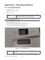
1
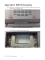
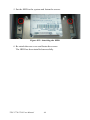
TPC-1770/1780
Intel Touch Panel Computer
with High Luminance 17"
SXGA TFT LCD
User Manual
Copyright
The documentation and the software included with this product are copyrighted 2008 by Advantech Co., Ltd. All rights are reserved. Advantech
Co., Ltd. reserves the right to make improvements in the products
described in this manual at any time without notice. No part of this manual may be reproduced, copied, translated or transmitted in any form or
by any means without the prior written permission of Advantech Co., Ltd.
Information provided in this manual is intended to be accurate and reliable. However, Advantech Co., Ltd. assumes no responsibility for its use,
nor for any infringements of the rights of third parties, which may result
from its use.
Acknowledgements
Intel and Pentium are trademarks of Intel Corporation.
Microsoft Windows and MS-DOS are registered trademarks of
Microsoft Corp.
All other product names or trademarks are properties of their respective
owners.
Part No. 2003177001
2nd Edition
Printed in Taiwan
January 2009
TPC-1770/1780 User Manual
ii
Product Warranty (2 years)
Advantech warrants to you, the original purchaser, that each of its products will be free from defects in materials and workmanship for two years
from the date of purchase.
This warranty does not apply to any products which have been repaired or
altered by persons other than repair personnel authorized by Advantech,
or which have been subject to misuse, abuse, accident or improper installation. Advantech assumes no liability under the terms of this warranty as
a consequence of such events.
Because of Advantech’s high quality-control standards and rigorous testing, most of our customers never need to use our repair service. If an
Advantech product is defective, it will be repaired or replaced at no
charge during the warranty period. For out-of-warranty repairs, you will
be billed according to the cost of replacement materials, service time and
freight. Please consult your dealer for more details.
If you think you have a defective product, follow these steps:
1.
Collect all the information about the problem encountered. (For
example, CPU speed, Advantech products used, other hardware
and software used, etc.) Note anything abnormal and list any
onscreen messages you get when the problem occurs.
2.
Call your dealer and describe the problem. Please have your manual, product, and any helpful information readily available.
3.
If your product is diagnosed as defective, obtain an RMA (return
merchandize authorization) number from your dealer. This allows
us to process your return more quickly.
4.
Carefully pack the defective product, a fully-completed Repair and
Replacement Order Card and a photocopy proof of purchase date
(such as your sales receipt) in a shippable container. A product
returned without proof of the purchase date is not eligible for warranty service.
5.
Write the RMA number visibly on the outside of the package and
ship it prepaid to your dealer.
iii
Declaration of Conformity
CE
This product has passed the CE test for environmental specifications
when shielded cables are used for external wiring. We recommend the use
of shielded cables. This kind of cable is available from Advantech. Please
contact your local supplier for ordering information.
FCC Class A
Note: This equipment has been tested and found to comply with the limits
for a Class A digital device, pursuant to part 15 of the FCC Rules. These
limits are designed to provide reasonable protection against harmful
interference when the equipment is operated in a commercial environment. This equipment generates, uses, and can radiate radio frequency
energy and, if not installed and used in accordance with the instruction
manual, may cause harmful interference to radio communications. Operation of this equipment in a residential area is likely to cause harmful interference in which case the user will be required to correct the interference
at his own expense.
Technical Support and Assistance
Step 1. Visit the Advantech web site at www.advantech.com/support
where you can find the latest information about the product.
Step 2. Contact your distributor, sales representative, or Advantech's customer service center for technical support if you need additional
assistance. Please have the following information ready before
you call:
- Product name and serial number
- Description of your peripheral attachments
- Description of your software (operating system, version, application software, etc.)
- A complete description of the problem
- The exact wording of any error messages
TPC-1770/1780 User Manual
iv
Safety Instructions
1.
Read these safety instructions carefully.
2.
Keep this User's Manual for later reference.
3.
Disconnect this equipment from any AC outlet before cleaning.
Use a damp cloth. Do not use liquid or spray detergents for cleaning.
4.
For plug-in equipment, the power outlet socket must be located
near the equipment and must be easily accessible.
5.
Keep this equipment away from humidity.
6.
Put this equipment on a reliable surface during installation. Dropping it or letting it fall may cause damage.
7.
The openings on the enclosure are for air convection. Protect the
equipment from overheating. DO NOT COVER THE OPENINGS.
8.
Make sure the voltage of the power source is correct before connecting the equipment to the power outlet.
9.
Position the power cord so that people cannot step on it. Do not
place anything over the power cord.
10.
All cautions and warnings on the equipment should be noted.
11.
If the equipment is not used for a long time, disconnect it from the
power source to avoid damage by transient overvoltage.
12.
Never pour any liquid into an opening. This may cause fire or electrical shock.
13.
Never open the equipment. For safety reasons, the equipment
should be opened only by qualified service personnel.
14.
If one of the following situations arises, get the equipment checked
by service personnel:
a. The power cord or plug is damaged.
b. Liquid has penetrated into the equipment.
c. The equipment has been exposed to moisture.
d. The equipment does not work well, or you cannot get it to work
according to the user's manual.
e. The equipment has been dropped and damaged.
f. The equipment has obvious signs of breakage.
15.
DO NOT LEAVE THIS EQUIPMENT IN AN ENVIRONMENT
WHERE THE STORAGE TEMPERATURE MAY GO BELOW v
20° C (-4° F) OR ABOVE 60° C (140° F). THIS COULD DAMAGE THE EQUIPMENT. THE EQUIPMENT SHOULD BE IN A
CONTROLLED ENVIRONMENT.
16.
CAUTION: DANGER OF EXPLOSION IF BATTERY IS
INCORRECTLY REPLACED. REPLACE ONLY WITH THE
SAME OR EQUIVALENT TYPE RECOMMENDED BY THE
MANUFACTURER, DISCARD USED BATTERIES ACCORDING TO THE MANUFACTURER'S INSTRUCTIONS.
The sound pressure level at the operator's position according to IEC 7041:1982 is no more than 70 dB (A).
DISCLAIMER: This set of instructions is given according to IEC 704-1.
Advantech disclaims all responsibility for the accuracy of any statements
contained herein.
TPC-1770/1780 User Manual
vi
Contents
Chapter
Chapter
1 General Information ....................................... 2
1.1
1.2
Introduction ....................................................................... 2
Specifications .................................................................... 2
1.3
1.4
1.5
1.6
LCD Specifications ........................................................... 4
Touchscreen Specifications............................................... 5
Power................................................................................. 5
I/O Port Arrangement........................................................ 6
1.7
Panel Mounting ................................................................. 7
1.8
Dimensions & Cutout........................................................ 8
1.2.1
1.2.2
1.2.3
System Kernel ................................................................ 2
I/O Ports ......................................................................... 3
Safety and Environment ................................................. 3
Figure 1.1:I/O Port Arrangement ................................... 6
Figure 1.2:Panel Mounting ............................................ 7
Figure 1.3:Dimensions ................................................... 8
2 System Setup.................................................. 10
Figure 2.1:Install CompactFlash memory card ............ 10
Figure 2.2:Power connector ......................................... 10
Figure 2.3:Power Receptor .......................................... 11
Figure 2.4:Power Button .............................................. 11
Chapter
3 I/O Connector & Setting Mode ................... 14
3.1
Chapter
CN1 (COM3, COM4), CN2A (COM1) ....................... 16
TPC-1780 ..................................................................... 17
COM1,COM3,COM4 : Serial port RS232 .................. 19
4 Software Configuration ................................ 22
4.1
Chapter
TPC-1770 ........................................................................ 14
3.1.1
3.1.2
3.1.3
Utilities & Drivers........................................................... 22
4.1.1
4.1.2
4.1.3
4.1.4
4.1.5
Intel Chipset Software Installation Utility ................... 22
VGA Drivers (Intel(R) Graphics Driver) ..................... 22
LAN Driver .................................................................. 23
Touchscreen Driver ...................................................... 23
Audio Driver ................................................................ 23
5 Windows XP Embedded ............................... 26
5.1
5.2
5.3
EWF ................................................................................ 26
HORM............................................................................. 26
Advantech Utilities.......................................................... 27
5.3.1
5.3.2
5.3.3
Version Information ..................................................... 27
EWF Enable and Disable ............................................. 27
HORM ......................................................................... 28
Appendix A WDT Programming ...................................... 30
A.1
Overview ......................................................................... 30
vii
Table of Contents
A.2
Watchdog Timer Programming....................................... 31
A.3
Example Programs .......................................................... 32
Table A.1:Watchdog Runtime Registers ..................... 31
Appendix B HDD Kit Assembly........................................ 44
Figure B.1:Removing the Rear HDD Cover ................ 44
Figure B.2:Removing the Top Screws ......................... 44
Figure B.3:Installing the HDD ..................................... 45
Figure B.4:Pasting the Mylar ....................................... 45
Figure B.5:Attaching the HDD .................................... 46
Appendix C Fuse Specifications ........................................ 48
C.1
C.2
Fuse Specifications.......................................................... 48
Fuse Replacement ........................................................... 48
Figure C.1:Fuse Replacement ...................................... 48
TPC-1770/1780 User Manual
viii
CHAPTER
1
2
General Information
Sections include:
• Introduction
• Specifications
• LCD Specifications
• Touchscreen Specifications
• Power
• I/O Ports Arrangement
• Panel Mounting
• Dimensions & Cutout
Chapter 1 General Information
1.1 Introduction
The TPC-1770/1780 TPC is state-of-the-art HMI. This 17" display operator interface is an x86-based platform with these key features:
Fanless:
By using a low power processor, the system does not have to rely on fans,
which are unreliable, and cause dust to circulate inside the equipment.
Bright Display:
The bright TFT LCD display suits industrial demands for clear interfaces.
Powerful Communication Capability:
The TPC-1770/1780 provides powerful IO interface for easily communicating with other devices. The IO interface includes serial ports, Ethernet
and USB 2.0 support.
Embedded Windows Support:
In addition to the OS support of Windows XP, Advantech offers platform
support for XP embedded.
1.2 Specifications
1.2.1 System Kernel
Item
TPC-1770H
TPC-1780H
CPU
BIOS
Intel® Celeron M 1GHz
w/ 0 L2 cache
Award 4MB
Intel® Core 2 Duo L7400
1.5GHz w/ 4M L2 cache
Award 4MB
North Bridge
915GME
945GME
South Bridge
ICH6M
ICH7M-DH
Memory
DIMM 240pin DDR2
400MHz, Single Channel, Default 512MB,
Up to 2G
CF Card Slot x 1
(TYPE Ⅱ )
2.5" SATA x 1
SO-DIMM 200pin DDR2
533MHz, Dual Channel,
Default 512MB x 2,
Up to 4G
CF Card Slot x 1
(TYPE Ⅱ )
2.5" SATA x 1
Super I/O SMSC
SCH3114, Interval 1sec
Super I/O SMSC
SCH3114, Interval 1sec
Storage
Watchdog timer
TPC-1770/1780 User Manual
2
1.2.2 I/O Ports
Item
TPC-1770H
TPC-1780H
I/O port
10/100/1000 Base-T x 2,
(Realtek RTK8111B)
10/100/1000 Base-T x 2,
(Realtek RTK8111B)
RS-232 x 3 (COM1,
COM3, COM4)
RS-232 x 3 (COM1,
COM3, COM4)
VGA x 1
VGA x 1
USB 2.0 x 4
USB 2.0 x 4
PS/2 Mouse interface x 1 PS/2 Mouse interface x 1
Expansion Bus
PS/2 Keyboard interface
x1
PS/2 Keyboard interface
x1
Mic-in, Line-in, Line-out
(AC97)
Mic-in, Line-in, Line-out
(AC97)
PCI
PCI-E x1 2ports
SDVO
LPC
USB 2ports
SMBUS
GPIO Support: NO
SerIRQ: Yes
PCI
PCI-E x1 4ports
SDVO
LPC
USB 2ports
SMBUS
GPIO Support: 2
SerIRQ: Yes
1.2.3 Safety and Environment
Safety
FCC Class A and CE certified
BSMI certified
UL certified
The front bezel is compliant with NEMA 4
Environment
Operating Temperature: 0~45° C
Storage Temperature: -20~70° C
Humidity: 10~95% @ 40 relative humidity (non-condensing)
Vibration: 1Grms (5~500Hz)
3
Chapter 1
1.3 LCD Specifications
Display Type
TFT color LCD
Size (diagonal)
17”
Maximum Resolution
1280 x 1024 (SXGA)
Maximum colors
16.7M colors
(RGB 6-bit + FRC data)
Pixel Pitch (W x H)
0.264 x 0.264 mm
Viewing Angle
160° (H), 160° (V); CR>=10
Luminance (cd / m2)
300
Contrast Ratio
800:1
Operating Temperature
0~50° C (Ambient)
Backlight
4 CCFL
Backlight Life Time
50,000 hours
Note
There might be several bright or dark pixels on the
LCD. This comes from the production of the LCD.
Such phenomenon is claimed to be normal according to the LCD manufacturers.
TPC-1770/1780 User Manual
4
1.4 Touchscreen Specifications
Touchscreen Type
Resistive
Base Glass Construction
Tempered Glass
Resolution
1024 x 1024
Light Transmission
80% typical
Controller
USB Interface
Power Rating
3.3 to 5V
Durability
1 million touches
1.5 Power
Input voltage: 18 ~ 32 Vdc, 5.55-3.12A Max (the fuse will be open
circuit as input level exceeds 33Vdc)
5
Chapter 1
1.6 I/O Port Arrangement
The arrangement of the I/O ports is shown in Figure 1.1.
Figure 1.1: I/O Port Arrangement
TPC-1770/1780 User Manual
6
1.7 Panel Mounting
1. There is a piece of adhesive waterproof gasket on the AL front
bezel. Make sure the waterproof gasket is in position before
installing the TPC-1770/1780 to the panel opening.
2. Install the TPC-1770/1780 to the panel opening.
3. Find out the ten clampers and ten long screws in the accessory
pack. Hook those clampers to those holes around the four sides
of the bezel. Insert the screws to every clamper and fasten them.
These screws will then push on the mounting panel and fix the
unit.
4. The mounting panel thickness is suggested to be less than 5.5mm
(0.216 inch).
Figure 1.2: Panel Mounting
7
Chapter 1
1.8 Dimensions & Cutout
Weight: 8 Kg (without HDD)
Dimensions: 414 x 347.5 x 93 mm (16.3" x 13.68" x 3.66") (WxHxD)
Cutout: 400.8 x 334.3 mm (suggested)
Figure 1.3: Dimensions
TPC-1770/1780 User Manual
8
CHAPTER
2
2
System Setup
Chapter 2 System Setup
This chapter provides a brief explanation for operating the TPC-1770/
1780. It is easy to make the TPC-1770/1780 start working with the below
step-by-step.
Step 1: Unpack the TPC-1770/1780 package. Please check the packing
list at the beginning of this manual.
Step 2: Install a CompactFlash containing Windows XP Embedded or
other operating system.
Figure 2.1: Install CompactFlash memory card
Warning
It is suggested to turn OFF system power as plug in
or pull out the memory card, though the CompactFlash memory is supposed to be hot swappable.
Step 3: Connect the power connector to the 24VDC power lines. The
power lines can either be of some power adapter or in-house power
source.
Figure 2.2: Power connector
TPC-1770/1780 User Manual
10
Figure 2.3: Power Receptor
Step 4: Plug the power lines to the system power receptor.
Step 5: Push the power button to power on the system as the figure 2.4.
Figure 2.4: Power Button
11
Chapter 2
TPC-1770/1780 User Manual
12
3
CHAPTER
2
I/O Connectors &
Setting Mode
Chapter 3 I/O Connector & Setting Mode
3.1 TPC-1770
TPC-1770/1780 User Manual
14
CN1A
COM3
RS-232 COM 3
CN1B
COM4
RS-232 COM4
CN2A
COM1
RS-232 COM1
CN2B
VGA port
Connector to VGA output
CN3
Audio Jack
Connector to Audio
CN4
PS/2 KB/MS
PS/2 connector for KB/MS
CN5A
LAN1
RTL8111B
CN5B,
CN5C
USB1, USB2
USB port
CN6A
LAN2
RTL8111B
CN6B,
CN6C
USB3, USB4
USB port
CN8
USB 5
USB optional port
CN9
USB 6
USB optional port
CN12
IDE Connector
2.5î IDE connector
CN13
ATX Connector
ATX power input
CN14
Inverter connector
Inverter power output
CN15
Touch connector
Connector Touch sensor
CN16
LVDS Connector
Connector LVDS panel
CN18
FAN connector
Connect CPU FAN
CN19
PANSWIN
Connector PW01
SA1
SATA Connector
SATA connector 1
SA2
SATA Connector
SATA connector 2
JP2
LCD resolution
LCD resolution selection
JP3
CMOS clear
Clear CMOS
15
Chapter 3
3.1.1 CN1 (COM3, COM4), CN2A (COM1)
Serial Port RS232 Connector Definitions
1
5
6
9
PIN
RS-232
1
2
3
4
5
6
7
8
9
NDCD
NRX
NTX
NDTR
GND
NDSR
NRTS
NCTS
NRI
TPC-1770/1780 User Manual
16
3.1.2 TPC-1780
CN15 CN2
CN21
CN12
CN3
CN4
CN18
CN19
CN20
JP1
CN16
CN9
SA1
CN8
SA2
CN11
CPU
CN1
II
JP2
JP3
JP4
ICH7M-DH
I
945GME
GF1
CN13
CLK
GF2
CN14
CN17
CN5
CN7
CN6
CN10
CN1
CN9
R41
CN3
CN2
CN7
4
CN6
3
CN10 CN8
2
1
CN5
5
17
Chapter 3
CON. #
Function
Description
CN1
CN2
CN3
DDR2 SO-DIM*2
INVERTER
INVERTER VRCtrl
CN4
CN5
CN6
LVDS
VGA + COM1
LAN1 + USB*2
Up to 4GB
TDK TBD266LR-1
Control inverter brightness by Digital VR
DS1804
Dual channels LVDS
VGA + Full DB9 Serial Port COM1
CN7
LAN2 + USB*2
CN8
CN9
CN10
CN11
CN12
CN13
CN14
CN15
CN16
USB
USB
AUDIO
BUZZER SELECT
CPU FAN
FWH
PS/2 KB + MS
TOUCH PANEL
IDE
CN17
CN18
COM3 + COM4
BOOT Ctrl
CN19
SNMP I2C BUS
CN20
CN21
SA1
SA2
JP1
BUZZER OUTPUT
ATX Power-input
SATA1
SATA2
LVDS PWR Select
JP2
CLEAR CMOS
JP3
BATTERY Verify
TPC-1770/1780 User Manual
10/100/1000MB Ethernet LAN1 + USB*2
10/100/1000MB Ethernet LAN2 + USB*2
Inside USB port 1
Inside USB port 2
Line-out / Line-in / MIC by ALC650
Select internal or external buzzer
CPU fan, work @ 12V
BIOS FWH, Flash P/N 46LF004B
PS/2 keyboard & mouse
8-wired touch panel sensor signals
Secondary IDE, Internal IDE
44pin(2mm) connector
Full DB9 Serial Port COM3 & COM4
Receive external push-button signal /
reset / HDDLED
I2C bus for SNMP measure, WINBOND
W83782G
External buzzer output, depend on CN11
Standard ATX Power input
Primary IDE, Master
Primary IDE, Slave
For 5V Panel: 1-2 (default) , For 3.3V
panel: 2-3
Normal: open (default) , Clear CMOS:
short
Normal: 1-2 (default) , just for battery
current measure
18
JP4
LVDS PANEL Sel.
1024 * 768 24bit
(Default)
1280 * 1024 48bit
800 * 600 24bit
1600*1200 48bit
VGA only
3.1.3 COM1,COM3,COM4 : Serial port RS232
Connector Definitions
1
6
5
9
Pin
Signal
1
NDCD
2
NRX
3
NTX
4
NDTR
5
GND
6
NDSR
7
NRTS
8
NCTS
9
NRI
19
Chapter 3
TPC-1770/1780 User Manual
20
CHAPTER
4
2
Software Configuration
Sections include:
• Utilities & Drivers
Chapter 4 Software Configuration
A support CD-ROM for TPC-1770/1780 is available and along with the
product. There are related utilities and drivers for TPC-1770/1780
included. Please install the Chipset INF driver, VGA graphics driver,
LAN driver, audio driver, Advantech.com driver, Touchscreen driver and
Watchdog Timer (WDT) driver sequentially.
4.1 Utilities & Drivers
The following utilities and drivers are provided for TPC-1770/1780. You
can also find the updated utilities and drivers from the support website.
4.1.1 Intel Chipset Software Installation Utility
Path: \TPC-1770H\XP\Chipset\
\TPC-1780H\XP\Chipset\
\TPC-1780H\VISTA32\Chipset\
\TPC-1780H\VISTA64\Chipset\
Available for the OS’s below:
• Microsoft Windows XP
• Microsoft Vista
4.1.2 VGA Drivers (Intel(R) Graphics Driver)
Path: \TPC-1770H\XP\VGA\
\TPC-1780H\XP\VGA\
\TPC-1780H\VISTA32\VGA\
\TPC-1780H\VISTA64\VGA\
Available for the OS’s below:
• Microsoft Windows XP
• Microsoft Vista
TPC-1770/1780 User Manual
22
4.1.3 LAN Driver
Path: \TPC-1770H\XP\LAN\
\TPC-1780H\XP\LAN\
\TPC-1780H\VISTA32\LAN\
\TPC-1780H\VISTA64\LAN\
Available for the OS’s below:
• Microsoft Windows XP
• Microsoft Vista
4.1.4 Touchscreen Driver
Path: \TPC-1770H\XP\TouchScreen\
\TPC-1780H\XP\TouchScreen\
\TPC-1780H\VISTA32\TouchScreen\
\TPC-1780H\VISTA64\TouchScreen\
Available for the OS’s below:
• Microsoft Windows XP
• Microsoft Vista
4.1.5 Audio Driver
Path: \TPC-1770H\XP\Audio\
\TPC-1780H\XP\Audio\
\TPC-1780H\VISTA32\Audio\
\TPC-1780H\VISTA64\Audio\
Available for the OS’s below:
• Microsoft Windows XP
• Microsoft Vista
23
Chapter 4
TPC-1770/1780 User Manual
24
CHAPTER
2
5
Windows XP Embedded
Sections include:
• EWF
• HORM
• Advantech Utilities
Chapter 5 Windows XP Embedded
TPC-1770/1780 is in support of embedded windows platform. This section is to state the important features, EWF and HORN, provided in windows XP embedded.
5.1 EWF
EWF stands for Enhanced Write Filter. It provides an upper filter in the
storage device driver stack that redirects disk write operations to volatile
(RAM) or non-volatile (disk) storage. EWF protects a volume from write
access. The benefits are as the following.
Write-protect one or more partitions on your system.
Enable read-only media, such as CD-ROM or flash, to boot and run.
Prolong the lifespan of write-sensitive storage, such as CompactFlash.
TPC-1770/1780 XPE provides EWF RAM RDG mode on system partition. All wirte to system partition will be redirected to RAM once this
mode is enabled. This mode is manually enabled by customers after they
finish all their changes on system such as installing their applications or
adjusting system setting.
Advantech provides a pair of utilities to operate EWF, OSLock and
OSUnLock. The setting is stated in the section later.
5.2 HORM
HORM stands for Hibernate Once Resume Many. In HORM environment, a single hibernation file is used to boot the system repeatedly. To
set a HORM environment, please follow the steps below.
Please make sure EWF is disabled. You can run OSUnLock to disable
EWF.
Enable hibernation support:
Run ‘power options’ in control panel, and then select ‘Enable Hibernation’ in hibernation pane.
TPC-1770/1780 User Manual
26
Enable EWF:
Run OSLock, and then system reboot automatically.
Open those software that customers want to directly use after system
resume from hibernation.
Hibernate via Advantech HORM utility:
Please Click Start Menu->All Programs->Advantech->HORM
HORM environment remains all along unless the following events occur:
Run EWF commit command (ewfmgr c: -commit) and then reboot.
Select “Discard hibernation file” by clicking F8 when system is starting
Also, HORM cannot fit your system if free space in C partition is not
enough. The hibernation file required is dependent on the RAM size you
use on the system. In other words, the hibernation file is 512MB that is
the same as memory size used on TPC-1770/1780.
5.3 Advantech Utilities
5.3.1 Version Information
Start menu-> All Programs -> Advantech
This states the current XPE runtime information including hardware platform, version, build number, release date, XPE QFEs installed in component database and XP Pro Patches you installed manually.
5.3.2 EWF Enable and Disable
The two utilities assist users to enable or disable EWF. Please go to Start
Menu-> All Programs-> Advantech. The default setting of EWF is disabled. Users can protect C partition from any disk writing via OSLock
that is to enable EWF RAM REG Mode. In this mode, any changes on C
partition including modification on files or registry will be redirected to
memory, thus these changes will be discarded in the next system startup.
To exit this environment is via OSUnLock. Please visit MSDN website
for further information about EWF.
27
Chapter 5
5.3.3 HORM
This is to create HORM environment. Please go to Start Menu-> All Programs-> Advantech. This utility firstly dismounts all local physical volumes that are not protected by EWF. It requires users to input the volume
list.
Please follow the steps before running this utility to create full HORM
environment.
Enable Hibernation via Power Options in Control Panel
Make C: partition EWF-enabled via OSLock
Make sure that all volumes to be dismounted are not in use.
TPC-1770/1780 User Manual
28
A
APPENDIX
2
Watchdog Timer
Programming
Appendix A WDT Programming
A.1 Overview
The TPC-1770/1780 cards’ watchdog timer can be used to monitor system software operation and take corrective action if the software fails to
function after the programmed period. This section describes the operation of the watchdog timer, and how to program it.
The watchdog timer is built into the super I/O controller
SMSC SCH3114. It provides the following functions for user programming:
• Can be enabled and disabled by user's program.
• Timer can be set from 1 to 255 seconds or 1 to 255 minutes.
• Generates an interrupt or resets signal if the software fails to reset the
timer after time-out.
TPC-1770/1780 User Manual
30
A.2 Watchdog Timer Programming
The I/O port address of the watchdog timer is 2E(hex) and 2F(hex), 2E
(hex) is the address port. 2F(hex) is the data port. You must first assign
the address of register by writing address value into address port 2E(hex),
then write/read data to/from the assigned register through data port 2F
(hex).
Table A.1: Watchdog Runtime Registers
Name
REG
OFFSET
(HEX)
DESCRIPTION
WDT_TIME_
OUT
65
Watch-dog Timeout
Bits[6:0] Reserved
Bit[7] WDT Time-out Value Units Select
= 0 Minutes
= 1 Seconds
WDT_VAL
66
Watch-dog Timer Time-out Value
Binary coded, units = minutes or seconds, selectable via Bit[7] of
WDT_TIME_OUT register (0x65).
0x00 Time out disabled
0x01 Time-out = 1 minute (second)
…..
0xFF Time-out = 255 minutes (seconds)
WDT_CFG
67
Bit[0] Reserved
Bit[1] Keyboard Enable
=1 WDT is reset upon a Keyboard interrupt.
=0 WDT is not affected by Keyboard
interrupts.
Bit[2] Mouse Enable
=1 WDT is reset upon a Mouse interrupt.
=0 WDT is not affected by Mouse interrupts.
Bit[7:3] Reserved
WDT_CTRL
68
Bit[1] Reserved
Bit[2] Force Timeout,
=1 Forces WD timeout event; this bit is
self-clearing
Bit[7:3] Reserved
31
Chapter A
A.3 Example Programs
1. Enable watchdog timer and set 10 seconds of timeout interval
;---------------------------; enter configuration state
;---------------------------mov
dx, 2Eh
mov
al, 55h
out
dx, al
;---------------------------; select watchdog registers
;---------------------------mov
al, 7
mov
dx, 2Eh
out
dx, al
mov
dx, 2Fh
mov
al, 0ah
out
dx, al
;---------------------------; get base address
;---------------------------mov
al, 60h
mov
dx, 2Eh
out
dx, al
mov
dx, 2Fh
in
al, dx
mov
ah, al
mov
al, 61h
TPC-1770/1780 User Manual
32
mov
dx, 2Eh
out
dx, al
mov
dx, 2Fh
in
al, dx
; now, AX contains the base address
mov
bx, ax ; save base address in BX
;---------------------------; exit configuration state
;---------------------------mov
dx, 2Eh
mov
al, 0AAh
out
dx, al
;---------------------------; select WDT pin
;---------------------------mov
dx, bx
add
dx, 47h
mov
al, 0Ch
out
dx, al
;---------------------------; select WDT timeout unit
;---------------------------mov
dx, bx
add
dx, 65h
mov
al, 80h
out
dx, al
; second
33
Chapter A
;---------------------------; select WDT timeout value
;---------------------------mov
dx, bx
add
dx, 66h
mov
al, 10
out
dx, al
; 10 seconds
2. Enable watchdog timer and set 5 minutes of timeout interval
;---------------------------; enter configuration state
;---------------------------mov
dx, 2Eh
mov
al, 55h
out
dx, al
;---------------------------; select watchdog registers
;---------------------------mov
al, 7
mov
dx, 2Eh
out
dx, al
mov
dx, 2Fh
mov
al, 0ah
out
dx, al
;---------------------------; get base address
;---------------------------mov
al, 60h
TPC-1770/1780 User Manual
34
mov
dx, 2Eh
out
dx, al
mov
dx, 2Fh
in
al, dx
mov
ah, al
mov
al, 61h
mov
dx, 2Eh
out
dx, al
mov
dx, 2Fh
in
al, dx
; now, AX contains the base address
mov
bx, ax ; save base address in BX
;---------------------------; exit configuration state
;---------------------------mov
dx, 2Eh
mov
al, 0AAh
out
dx, al
;---------------------------; select WDT pin
;---------------------------mov
dx, bx
add
dx, 47h
mov
al, 0Ch
out
dx, al
35
Chapter A
;---------------------------; select WDT timeout unit
;---------------------------mov
dx, bx
add
dx, 65h
mov
al, 00h
out
dx, al
; minute
;---------------------------; select WDT timeout value
;---------------------------mov
dx, bx
add
dx, 66h
mov
al, 5
out
dx, al
; 5 minutes
3. Enable watchdog timer to be reset upon mouse interrupt
(Note: WDT timeout value must be set before this function can work)
;---------------------------; enter configuration state
;---------------------------mov
dx, 2Eh
mov
al, 55h
out
dx, al
;---------------------------; select watchdog registers
;---------------------------mov
al, 7
mov
dx, 2Eh
TPC-1770/1780 User Manual
36
out
dx, al
mov
dx, 2Fh
mov
al, 0ah
out
dx, al
;---------------------------; get base address
;---------------------------mov
al, 60h
mov
dx, 2Eh
out
dx, al
mov
dx, 2Fh
in
al, dx
shl
al, 8
mov
al, 61h
mov
dx, 2Eh
out
dx, al
mov
dx, 2Fh
in
al, dx
; now, AX contains the base address
mov
bx, ax ; save base address in BX
;---------------------------; exit configuration state
;---------------------------mov
dx, 2Eh
mov
al, 0AAh
out
dx, al
37
Chapter A
;---------------------------; select WDT configuration
;---------------------------mov
dx, bx
add
dx, 67h
in
al, dx
or
al, 04h
out
dx, al
; reset upon mouse interrupt
4. Enable watchdog timer to be reset upon keyboard interrupt
(Note: WDT timeout value must be set before this function can work)
;---------------------------; enter configuration state
;---------------------------mov
dx, 2Eh
mov
al, 55h
out
dx, al
;---------------------------; select watchdog registers
;---------------------------mov
al, 7
mov
dx, 2Eh
out
dx, al
mov
dx, 2Fh
mov
al, 0ah
out
dx, al
;---------------------------; get base address
TPC-1770/1780 User Manual
38
;---------------------------mov
al, 60h
mov
dx, 2Eh
out
dx, al
mov
dx, 2Fh
in
al, dx
shl
al, 8
mov
al, 61h
mov
dx, 2Eh
out
dx, al
mov
dx, 2Fh
in
al, dx
; now, AX contains the base address
mov
bx, ax ; save base address in BX
;---------------------------; exit configuration state
;---------------------------mov
dx, 2Eh
mov
al, 0AAh
out
dx, al
;---------------------------; select WDT configuration
;---------------------------mov
dx, bx
add
dx, 67h
in
al, dx
39
Chapter A
or
al, 02h
out
dx, al
; reset upon keyboard interrupt
5. Force timeout
(Note: WDT timeout value must be set before this function can work)
;---------------------------; enter configuration state
;---------------------------mov
dx, 2Eh
mov
al, 55h
out
dx, al
;---------------------------; select watchdog registers
;---------------------------mov
al, 7
mov
dx, 2Eh
out
dx, al
mov
dx, 2Fh
mov
al, 0ah
out
dx, al
;---------------------------; get base address
;---------------------------mov
al, 60h
mov
dx, 2Eh
out
dx, al
mov
dx, 2Fh
in
al, dx
TPC-1770/1780 User Manual
40
shl
al, 8
mov
al, 61h
mov
dx, 2Eh
out
dx, al
mov
dx, 2Fh
in
al, dx
; now, AX contains the base address
mov
bx, ax ; save base address in BX
;---------------------------; exit configuration state
;---------------------------mov
dx, 2Eh
mov
al, 0AAh
out
dx, al
;---------------------------; Force timeout
;---------------------------mov
dx, bx
add
dx, 68h
in
al, dx
or
al, 04h
out
dx, al
; force timeout
41
Chapter A
TPC-1770/1780 User Manual
42
B
APPENDIX
2
HDD Kit Assembly
Appendix B HDD Kit Assembly
Please follow the assembly procedure to install the HDD into the system.
1.
Remove the rear HDD cover.
Figure B.1: Removing the Rear HDD Cover
2.
Deassemble the HDD kit from the system.
Figure B.2: Removing the Top Screws
TPC-1770/1780 User Manual
44
3.
Put the HDD into the HDD bracket and fasten the screws..
Figure B.3: Installing the HDD
4.
Paste the Mylar (from assembly box)
Figure B.4: Pasting the Mylar
45
Appendix B
5. Put the HDD to the system and fasten the screws.
Figure B.5: Attaching the HDD
6. Re-attach the rear cover and fasten the screws.
The HDD has been installed successfully.
TPC-1770/1780 User Manual
46
C
APPENDIX
2
Fuse Specifications
Appendix C Fuse Specifications
C.1 Fuse Specifications
Rating: 250VAC, 5Amp
Size: 5 x 20mm
Note
The fuse is set to break as the input voltage
exceeds 33VDC for your protection.
C.2 Fuse Replacement
Step 1: Remove the fuse cover
Step 2: Replace the damaged fuse with a new one
Step 3: Place the fuse cover back in position
Figure C.1: Fuse Replacement
Warning
Do NOT replace the fuse unless it is damaged.
Do NOT replace the fuse with a different rating.
TPC-1770/1780 User Manual
48