1
User's Manual
CubeSuite+ V1.03.00
Integrated Development Environment
User's Manual: Build for CX Compiler
Target Device
V850 Family
All information contained in these matenals, including products and product specifications,
represents information on the product at the time of publication and is subject to change by
Renesas Electronics Corp. without notice. Please review the latest information published by
Renesas Electronics Corp. through various means, including the Renesas Electronics Corp.
website (http://www.renesas.com).
www.renesas.com
Rev.1.00 Sep 2012
Notice
1.
Descriptions of circuits, software and other related information in this document are provided only to illustrate the operation of
semiconductor products and application examples. You are fully responsible for the incorporation of these circuits, software,
and information in the design of your equipment. Renesas Electronics assumes no responsibility for any losses incurred by you
or third parties arising from the use of these circuits, software, or information.
2.
Renesas Electronics has used reasonable care in preparing the information included in this document, but Renesas Electronics
does not warrant that such information is error free. Renesas Electronics assumes no liability whatsoever for any damages
incurred by you resulting from errors in or omissions from the information included herein.
3.
Renesas Electronics does not assume any liability for infringement of patents, copyrights, or other intellectual property rights of
third parties by or arising from the use of Renesas Electronics products or technical information described in this document. No
license, express, implied or otherwise, is granted hereby under any patents, copyrights or other intellectual property rights of
Renesas Electronics or others.
4.
You should not alter, modify, copy, or otherwise misappropriate any Renesas Electronics product, whether in whole or in part.
Renesas Electronics assumes no responsibility for any losses incurred by you or third parties arising from such alteration,
modification, copy or otherwise misappropriation of Renesas Electronics product.
5.
Renesas Electronics products are classified according to the following two quality grades: “Standard” and “High Quality”. The
recommended applications for each Renesas Electronics product depends on the product’s quality grade, as indicated below.
“Standard”:
Computers; office equipment; communications equipment; test and measurement equipment; audio and visual
equipment; home electronic appliances; machine tools; personal electronic equipment; and industrial robots etc.
“High Quality”: Transportation equipment (automobiles, trains, ships, etc.); traffic control systems; anti-disaster systems; anticrime systems; and safety equipment etc.
Renesas Electronics products are neither intended nor authorized for use in products or systems that may pose a direct threat to
human life or bodily injury (artificial life support devices or systems, surgical implantations etc.), or may cause serious property
damages (nuclear reactor control systems, military equipment etc.). You must check the quality grade of each Renesas
Electronics product before using it in a particular application. You may not use any Renesas Electronics product for any
application for which it is not intended. Renesas Electronics shall not be in any way liable for any damages or losses incurred
by you or third parties arising from the use of any Renesas Electronics product for which the product is not intended by Renesas
Electronics.
6.
You should use the Renesas Electronics products described in this document within the range specified by Renesas Electronics,
especially with respect to the maximum rating, operating supply voltage range, movement power voltage range, heat radiation
characteristics, installation and other product characteristics. Renesas Electronics shall have no liability for malfunctions or
damages arising out of the use of Renesas Electronics products beyond such specified ranges.
7.
Although Renesas Electronics endeavors to improve the quality and reliability of its products, semiconductor products have
specific characteristics such as the occurrence of failure at a certain rate and malfunctions under certain use conditions. Further,
Renesas Electronics products are not subject to radiation resistance design. Please be sure to implement safety measures to
guard them against the possibility of physical injury, and injury or damage caused by fire in the event of the failure of a Renesas
Electronics product, such as safety design for hardware and software including but not limited to redundancy, fire control and
malfunction prevention, appropriate treatment for aging degradation or any other appropriate measures. Because the evaluation
of microcomputer software alone is very difficult, please evaluate the safety of the final products or systems manufactured by
you.
8.
Please contact a Renesas Electronics sales office for details as to environmental matters such as the environmental compatibility
of each Renesas Electronics product. Please use Renesas Electronics products in compliance with all applicable laws and
regulations that regulate the inclusion or use of controlled substances, including without limitation, the EU RoHS Directive.
Renesas Electronics assumes no liability for damages or losses occurring as a result of your noncompliance with applicable laws
and regulations.
9.
Renesas Electronics products and technology may not be used for or incorporated into any products or systems whose
manufacture, use, or sale is prohibited under any applicable domestic or foreign laws or regulations. You should not use
Renesas Electronics products or technology described in this document for any purpose relating to military applications or use
by the military, including but not limited to the development of weapons of mass destruction. When exporting the Renesas
Electronics products or technology described in this document, you should comply with the applicable export control laws and
regulations and follow the procedures required by such laws and regulations.
10. It is the responsibility of the buyer or distributor of Renesas Electronics products, who distributes, disposes of, or otherwise
places the product with a third party, to notify such third party in advance of the contents and conditions set forth in this
document, Renesas Electronics assumes no responsibility for any losses incurred by you or third parties as a result of
unauthorized use of Renesas Electronics products.
11. This document may not be reproduced or duplicated in any form, in whole or in part, without prior written consent of Renesas
Electronics.
12. Please contact a Renesas Electronics sales office if you have any questions regarding the information contained in this document
or Renesas Electronics products, or if you have any other inquiries.
(Note 1) “Renesas Electronics” as used in this document means Renesas Electronics Corporation and also includes its majorityowned subsidiaries.
(Note 2) “Renesas Electronics product(s)” means any product developed or manufactured by or for Renesas Electronics.
(2012.4)
How to Use This Manual
This manual describes the role of the CubeSuite+ integrated development environment for developing applications and
systems for V850 family, and provides an outline of its features.
CubeSuite+ is an integrated development environment (IDE) for V850 family, integrating the necessary tools for the
development phase of software (e.g. design, implementation, and debugging) into a single platform.
By providing an integrated environment, it is possible to perform all development using just this product, without the
need to use many different tools separately.
Readers
This manual is intended for users who wish to understand the functions of the
CubeSuite+ and design software and hardware application systems.
Purpose
This manual is intended to give users an understanding of the functions of the
CubeSuite+ to use for reference in developing the hardware or software of systems
using these devices.
Organization
This manual can be broadly divided into the following units.
CHAPTER 1 GENERAL
CHAPTER 2 FUNCTIONS
CHAPTER 3 BUILD OUTPUT LISTS
APPENDIX A WINDOW REFERENCE
APPENDIX B COMMAND REFERENCE
APPENDIX C INDEX
How to Read This Manual
It is assumed that the readers of this manual have general knowledge of electricity,
logic circuits, and microcontrollers.
Conventions
Data significance:
Higher digits on the left and lower digits on the right
Active low representation:
XXX (overscore over pin or signal name)
Note:
Footnote for item marked with Note in the text
Caution:
Information requiring particular attention
Remark:
Supplementary information
Numeric representation:
Decimal ... XXXX
Hexadecimal ... 0xXXXX
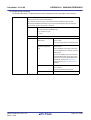
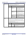
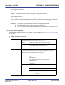
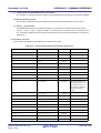
Related Documents
The related documents indicated in this publication may include preliminary versions.
However, preliminary versions are not marked as such.
Document Name
CubeSuite+
Integrated Development Environment
Document No.
Start
R20UT2133E
V850 Design
R20UT2134E
R8C Design
R20UT2135E
RL78 Design
R20UT2136E
78K0R Design
R20UT2137E
78K0 Design
R20UT2138E
RX Coding
R20UT0767E
V850 Coding
R20UT0553E
Coding for CX Compiler
R20UT2139E
R8C Coding
R20UT0576E
RL78, 78K0R Coding
R20UT2140E
78K0 Coding
R20UT2141E
RX Build
R20UT0768E
V850 Build
R20UT0557E
Build for CX Compiler
This manual
R8C Build
R20UT0575E
RL78, 78K0R Build
R20UT2143E
78K0 Build
R20UT0783E
RX Debug
R20UT2175E
V850 Debug
R20UT2144E
R8C Debug
R20UT0770E
RL78 Debug
R20UT2145E
78K0R Debug
R20UT0732E
78K0 Debug
R20UT0731E
Analysis
R20UT2146E
Message
R20UT2147E
User's Manual
Caution
The related documents listed above are subject to change without
notice. Be sure to use the latest edition of each document when
designing.
All trademarks or registered trademarks in this document are the property of their respective owners.
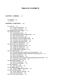
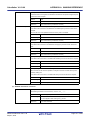
TABLE OF CONTENTS
CHAPTER 1 GENERAL ... 8
1.1 Overview ... 8
1.2 Features ... 9
CHAPTER 2 FUNCTIONS ... 10
2.1 Overview ... 10
2.1.1 Create a load module ... 10
2.1.2 Create a user library ... 11
2.2 Change the Build Tool Version ... 12
2.3 Set Build Target Files ... 13
2.3.1 Set a startup routine ... 13
2.3.2 Automatically generate link directives ... 15
2.3.3 Add a file to a project ... 20
2.3.4 Remove a file from a project ... 24
2.3.5 Remove a file from the build target ... 25
2.3.6 Classify a file into a category ... 25
2.3.7 Change the file display order ... 26
2.3.8 Update file dependencies ... 27
2.4 Set the Type of the Output File ... 30
2.4.1 Change the output file name ... 30
2.4.2 Output an assemble list ... 32
2.4.3 Output map information ... 32
2.4.4 Output symbol information ... 33
2.5 Set Compile Options ... 34
2.5.1 Perform optimization with the code size precedence ... 35
2.5.2 Perform optimization with the execution speed precedence ... 35
2.5.3 Add an include path ... 35
2.5.4 Set a macro definition ... 37
2.5.5 Reduce the code size (perform prologue/epilogue runtime calls) ... 38
2.5.6 Change the register mode ... 38
2.6 Set Assemble Options ... 39
2.6.1 Add an include path ... 39
2.6.2 Set a macro definition ... 41
2.7 Set Link Options ... 43
2.7.1 Add a user library ... 43
2.8 Set ROMize Options ... 45
2.8.1 Create a ROMized load module ... 45
2.9 Set Hex Output Options ... 47
2.9.1 Set the output of a hex file ... 47
2.9.2 Fill the vacant area ... 49
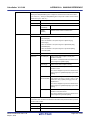
2.10 Set Create Library Options ... 50
2.11
2.12
2.13
2.14
2.15
2.16
2.17
2.10.1 Set the output of a library file ... 50
Set Build Options Separately ... 51
2.11.1 Set build options at the project level ... 51
2.11.2 Set build options at the file level ... 51
Prepare for Implementing Boot-Flash Relink Function ... 54
2.12.1 Prepare the build target files ... 54
2.12.2 Set the boot area project ... 54
2.12.3 Set the flash area project ... 56
Allocate Variables to Optimum Section ... 58
Create a Multi-Core Load Module ... 62
Make Settings for Build Operations ... 65
2.15.1 Import the build options of other project ... 65
2.15.2 Set the link order of files ... 66
2.15.3 Change the file build order of subprojects ... 69
2.15.4 Display a list of build options ... 70
2.15.5 Change the file build target project ... 70
2.15.6 Add a build mode ... 72
2.15.7 Change the build mode ... 73
2.15.8 Delete a build mode ... 75
2.15.9 Set the current build options as the standard for the project ... 76
Run a Build ... 77
2.16.1 Run a build of updated files ... 79
2.16.2 Run a build of all files ... 80
2.16.3 Run a build in parallel with other operations ... 80
2.16.4 Run builds in batch with build modes ... 81
2.16.5 Compile/assemble/link multiple files simultaneously ... 83
2.16.6 Compile/assemble individual files ... 84
2.16.7 Stop running a build ... 85
2.16.8 Save the build results to a file ... 85
2.16.9 Delete intermediate files and generated files ... 86
Estimate the Stack Capacity ... 87
2.17.1 Starting and exiting ... 87
2.17.2 Check the call relationship ... 88
2.17.3 Check the stack information ... 88
2.17.4 Check unknown functions ... 89
2.17.5 Change the frame size ... 89
CHAPTER 3 BUILD OUTPUT LISTS ... 91
3.1
3.2
3.3
3.4
Assemble List File ... 91
Link Map File ... 93
Symbol Information File ... 98
Hex File ... 101
3.4.1 Intel expanded hex format ... 102
3.4.2 Motorola S type hex format ... 107
3.4.3 Expanded Textronix hex format ... 110
APPENDIX A WINDOW REFERENCE ... 115
A.1 Description ... 115
APPENDIX B COMMAND REFERENCE ... 326
B.1 cx ... 326
B.1.1 I/O files ... 329
B.1.2 Method for manipulating ... 330
B.1.3 Option ... 333
B.1.4 Symbol information file ... 553
B.1.5 Optimization function ... 556
B.1.6 Boot-flash re-link function ... 559
B.1.7 Cautions ... 568
B.2 Librarian ... 575
B.2.1 I/O files ... 575
B.2.2 Method for manipulating ... 576
B.2.3 Key/Option ... 577
B.3 Source Converter ... 594
B.3.1 I/O files ... 594
B.3.2 Method for manipulating ... 595
B.3.3 Option ... 597
B.3.4 Conversion specification ... 605
APPENDIX C INDEX ... 612
CubeSuite+ V1.03.00
CHAPTER 1 GENERAL
CHAPTER 1 GENERAL
This chapter explains the overview of the build tool (CX).
1.1
Overview
The build tool (CX) is comprised of components provided by this product. It enables various types of information to be
configured via a GUI tool, enabling you to generate the load module file, ROMization load module file, hex file, and user
library file from your source files, according to your objectives.
CX described by this manual consists of the following commands.
- cx
- Librarian
- Source Converter
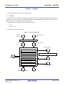
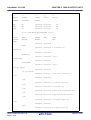
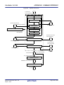
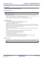
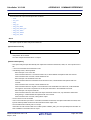
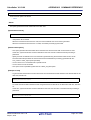
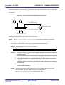
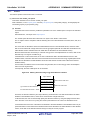
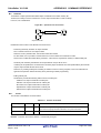
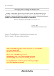
The process flow of CX is shown below.
Figure 1-1. Process Flow of CX
C source file
Assembler source file
(CA850)
(CA850)
Source converter
C source file
Assembler source file
(CX)
(CX)
Object module file
cx
Compiler
Assembler
Librarian
Linker
Load module file
Symbol file generator
User library file
ROMization processor
Object converter
Standard library file, etc.
ROMization load module file
R20UT2142EJ0100 Rev.1.00
Sep 01, 2012
Hex file
Page 8 of 620
CubeSuite+ V1.03.00
1.2
CHAPTER 1 GENERAL
Features
The features of the build tool (CX) are shown below.
- Optimization function
You can generate efficient load module files by performing optimizations such as prioritizing code size or execution
speed when compiling.
- Support for 8-byte types (double and long long)
CX treats double as an 8-byte type.
It also supports the long long type (signed / unsigned) specified by C99.
- Smart correction function
If you want to correct a specific function, you can replace just the processing in that function without changing the
contents of any other functions (code or addresses).
Remark
See "CubeSuite+ Integrated Development Environment User’s Manual: Coding for CX Compiler" for
details about the smart correction function.
- Linking continues after error
If there is a memory overflow error, if CX can recover then it will continue linking, and display information about low
memory.
R20UT2142EJ0100 Rev.1.00
Sep 01, 2012
Page 9 of 620
CubeSuite+ V1.03.00
CHAPTER 2 FUNCTIONS
CHAPTER 2 FUNCTIONS
This chapter describes the build procedure using CubeSuite+ and about the main build functions.
2.1
Overview
This section describes how to create a load module and user library.
Remark
2.1.1
See "B.3 Source Converter" for details about conversion from CA850 files to CX files.
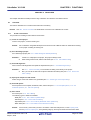
Create a load module
The procedure for creating a load module is shown below.
(1) Create or load a project
Create a new project, or load an existing one.
Remark
See "CubeSuite+ Integrated Development Environment User’s Manual: Start" for details about creating
a new project or loading an existing one.
(2) Set a build target project
Set a build target project (see "2.15 Make Settings for Build Operations").
Remarks 1.
2.
If there is no subproject in the project, the project is always active.
When setting a build mode, add the build mode (see "2.15.6 Add a build mode").
(3) Set build target files
Add or remove build target files and update the dependencies (see "2.3 Set Build Target Files").
Remarks 1.
2.
See "2.7.1 Add a user library" for the method of adding a user library to the project.
Also, you can set the link order of object module files and library files (see "2.15.2 Set the link
order of files").
(4) Specify the output of a load module
Select the type of the load module to be generated (see "2.4 Set the Type of the Output File").
(5) Set build options
Set the options for the compiler, assembler, linker, and the like (see "2.5 Set Compile Options", "2.6 Set
Assemble Options", "2.7 Set Link Options").
(6) Run a build
Run a build (see "2.16 Run a Build").
The following types of builds are available.
- Build (see "2.16.1 Run a build of updated files")
- Rebuild (see "2.16.2 Run a build of all files")
- Rapid build (see "2.16.3 Run a build in parallel with other operations")
- Batch build (see "2.16.4 Run builds in batch with build modes")
Remark
If there are any commands you wish to run before or after the build process, on the Property panel,
from the [Common Options] tab, in the [Others] category, set the [Commands executed before build
R20UT2142EJ0100 Rev.1.00
Sep 01, 2012
Page 10 of 620
CubeSuite+ V1.03.00
CHAPTER 2 FUNCTIONS
processing] and [Commands executed after build processing] properties.
If there are any commands you wish to run before or after the build process at the file level, you can set
them from the [Individual Compile Options] tab (for a C source file) and [Individual Assemble Options]
tab (for an assembler source file).
(7) Save the project
Save the setting contents of the project to the project file.
Remark
See "CubeSuite+ Integrated Development Environment User’s Manual: Start" for details about saving
the project.
2.1.2
Create a user library
The procedure for creating a user library is shown below.
(1) Create or load a project
Create a new project, or load an existing one.
When you create a new project, set a library project.
Remark
See "CubeSuite+ Integrated Development Environment User’s Manual: Start" for details about creating
a new project or loading an existing one.
(2) Set a build target project
Set a build target project (see "2.15 Make Settings for Build Operations").
Remarks 1.
2.
If there is no subproject in the project, the project is always active.
When setting a build mode, add the build mode (see "2.15.6 Add a build mode").
(3) Set build target files
Add or remove build target files and update the dependencies (see "2.3 Set Build Target Files").
(4) Set build options
Set the options for the compiler, assembler, librarian, and the like (see "2.5 Set Compile Options", "2.6 Set
Assemble Options", "2.10 Set Create Library Options").
Remark
To create a library common to various devices, set the [Output common object module file for various
devices] property in the [Output File Type and Path] category from the [Common Options] tab on the
Property panel.
(5) Run a build
Run a build (see "2.16 Run a Build").
The following types of builds are available.
- Build (see "2.16.1 Run a build of updated files")
- Rebuild (see "2.16.2 Run a build of all files")
- Rapid build (see "2.16.3 Run a build in parallel with other operations")
- Batch build (see "2.16.4 Run builds in batch with build modes")
Remark
If there are any commands you wish to run before or after the build process, on the Property panel,
from the [Common Options] tab, in the [Others] category, set the [Commands executed before build
processing] and [Commands executed after build processing] properties.
R20UT2142EJ0100 Rev.1.00
Sep 01, 2012
Page 11 of 620
CubeSuite+ V1.03.00
CHAPTER 2 FUNCTIONS
If there are any commands you wish to run before or after the build process at the file level, you can set
them from the [Individual Compile Options] tab (for a C source file) and [Individual Assemble Options]
tab (for an assembler source file).
(6) Save the project
Save the setting contents of the project to the project file.
Remark
See "CubeSuite+ Integrated Development Environment User’s Manual: Start" for details about saving
the project.
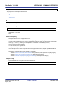
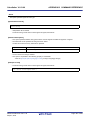
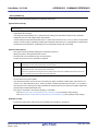
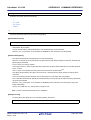
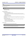
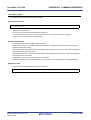
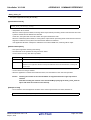
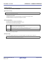
2.2
Change the Build Tool Version
You can change the version of the build tool (compiler package) used in the project (main project or subproject).
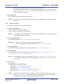
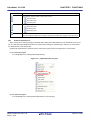
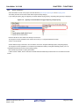
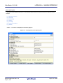
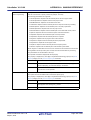
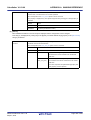
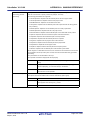
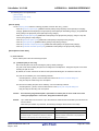
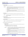
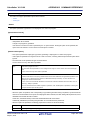
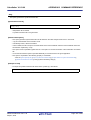
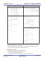
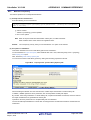
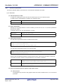
Select the build tool node on the project tree and select the [Common Options] tab on the Property panel. Select
[Always latest version which was installed] or the version in the [Using compiler package version] property in the [Version
Select] category.
Figure 2-1. [Using compiler package version] Property
Remarks 1.
When the build tool used in the main project and subprojects is the same, you can collectively change
the build tool version by selecting all of the Build tool nodes and setting the property.
2.
If you have selected a compiler package that has not been installed (e.g. if you open a project created
in another execution environment), then that version is also displayed.
3.
If the options change depending on the compiler package, then the display of the build tool's properties
will change according to the selected version.
Properties that are hidden when the version is changed are saved in the project file's settings, and the
values will be reproduced when the properties are displayed again.
Options are changed in accordance with the following rules. Information about changes is displayed in
the Output panel.
- If you change from an older version to a newer version, the option settings will be inherited and
converted (only if necessary).
- If you change from a newer version to an older version, only identical option settings will be
inherited.
Options that only exist in the older version will be set to the default values.
R20UT2142EJ0100 Rev.1.00
Sep 01, 2012
Page 12 of 620
CubeSuite+ V1.03.00
2.3
CHAPTER 2 FUNCTIONS
Set Build Target Files
Before running a build, you must add the build target files (such as C source file, assembler source file) to the project.
This section explains operations on setting files in the project.
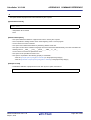
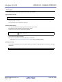
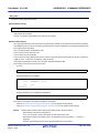
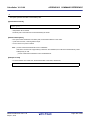
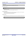
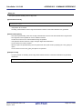
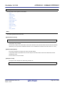
2.3.1
Set a startup routine
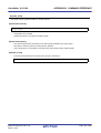
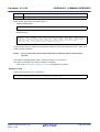
(1) Using the standard startup routine
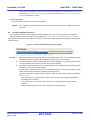
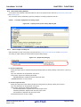
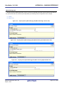
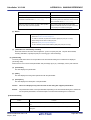
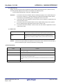
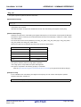
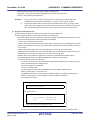
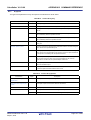
Select the build tool node on the project tree and select the [Link Options] tab on the Property panel.
To use the standard startup routine (object module file provided with CX), select [Yes] in the [Use standard startup
routine] property in the [Input File] category.
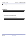
Figure 2-2. [Use standard startup routine] Property
Remark
In the [Output ROMized load module file] property in the [Output File] category from the [ROMize
Options] tab, "cstart.obj" is linked when [Yes] is selected and "cstartN.obj" is linked when [No(Xno_romize)] is selected.
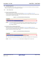
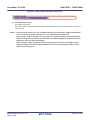
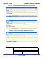
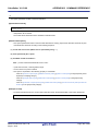
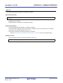
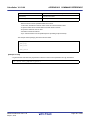
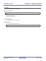
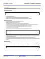
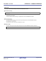
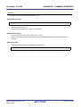
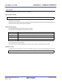
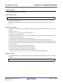
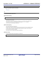
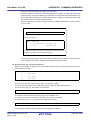
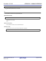
(2) Using other than the standard startup routine
Select the build tool node on the project tree and select the [Link Options] tab on the Property panel.
To use other than the standard startup routine, select [No(-Xno_startup)] in the [Use standard startup routine]
property in the [Input File] category (default: [Yes]).
Figure 2-3. [Use standard startup routine] Property
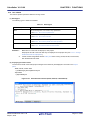
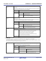
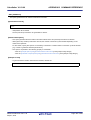
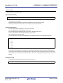
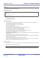
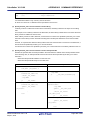
Next, add the startup file (the file that the startup routine is described) to the Startup node on the project tree.
Remark
See "2.3.3 Add a file to a project" for the method of adding the file to the project tree.
R20UT2142EJ0100 Rev.1.00
Sep 01, 2012
Page 13 of 620
CubeSuite+ V1.03.00
CHAPTER 2 FUNCTIONS
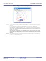
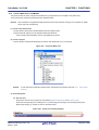
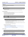
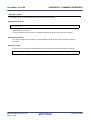
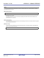
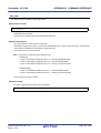
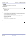
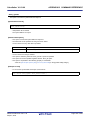
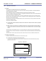
Figure 2-4. Project Tree Panel (After Adding Startup File)
Caution
The build target file added directly below the Startup node on the project tree is treated as the
startup file.
It is not treated as a startup file if it is added to the category below the Startup node.
When adding the startup file to the Startup node, if a startup file has already been added then
only the latest startup file to be added is targeted by a build; any such files added prior to this
one will not be targeted.
When setting the startup file that is not targeted by a build as the build target, if other startup
files have also been added then the file will be targeted by the build, and the others will not be
targeted.
Remark
See "CubeSuite+ Integrated Development Environment User’s Manual: Coding for CX Compiler" for
the method of creating the startup routine.
R20UT2142EJ0100 Rev.1.00
Sep 01, 2012
Page 14 of 620
CubeSuite+ V1.03.00
2.3.2
CHAPTER 2 FUNCTIONS
Automatically generate link directives
Although users can create a link directive file and add it to a project, it is also possible to generate it automatically in
CubeSuite+.
Remark
See "CubeSuite+ Integrated Development Environment User’s Manual: Coding for CX Compiler" for details
about link directives and creating a link directive file.
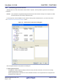
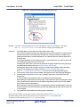
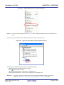
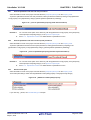
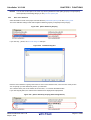
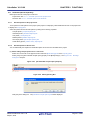
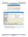
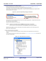
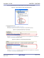
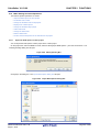
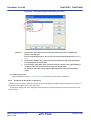
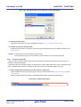
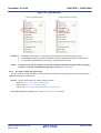
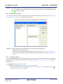
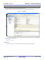
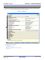
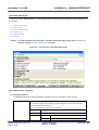
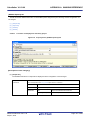
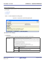
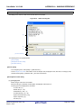
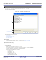
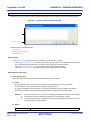
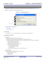
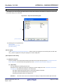
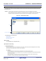
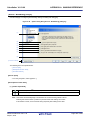
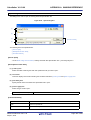
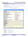
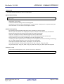
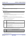
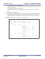
On the project tree, select the Build tool node, and then select [Create Link Directive File...] from the context menu.
The Link Directive File Generation dialog box opens.
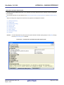
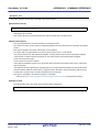
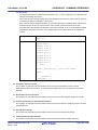
Figure 2-5. Link Directive File Generation Dialog Box
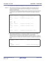
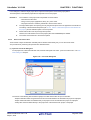
Edit the segments/sections and symbols in the dialog box.
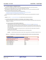
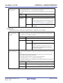
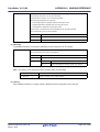
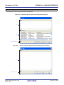
(1) Edit segments/sections
The [Segment / Section list] area displays the device memory allocation information, and a list of the currently
configured segments and sections.
When a segment/section is selected from the list, detailed information on that segment/section is displayed in the
[Segment/Section detail] area.
R20UT2142EJ0100 Rev.1.00
Sep 01, 2012
Page 15 of 620
CubeSuite+ V1.03.00
CHAPTER 2 FUNCTIONS
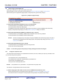
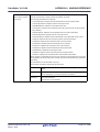
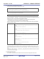
Edit the items in the [Segment / Section detail] area.
Remark
Some items in reserved sections cannot be edited (items for which values are set automatically).
See "APPENDIX A WINDOW REFERENCE", "Link Directive File Generation dialog box" for details
about each item and how reserved sections are handled.
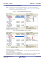
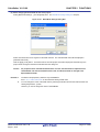
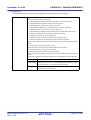
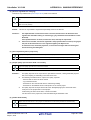
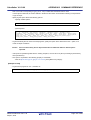
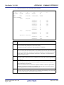
Figure 2-6. Segment Detail (When SCONST Is Selected)
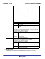
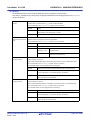
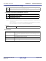
Figure 2-7. Section Detail (When .sconst Is Selected)
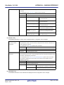
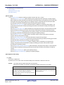
Segments and sections can also be added.
Click [Add Segment] to add a new segment "NewSegment_XXX" directly below the row selected in the list (XXX: 0
to 255 in decimal numbers).
Edit the items in the [Segment / Section detail] area.
By default, [Attribute] is set to [Executable(RX)] (if added to the internal ROM area or non mapping area), to [Read/
Write(RW)] (if added to the internal RAM area), or to [Read only(R)] (if added to the DataFlash area).
R20UT2142EJ0100 Rev.1.00
Sep 01, 2012
Page 16 of 620
CubeSuite+ V1.03.00
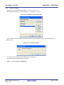
Caution
CHAPTER 2 FUNCTIONS
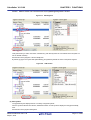
When a section row is selected in the list, the [Add Segment] button is invalid.
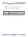
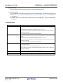
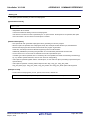
Figure 2-8. Add Segment
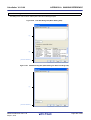
Click [Add Section] to add a new section "NewSection_XXX" directly below the row selected in the list (XXX: 0 to
255 in decimal numbers).
Edit the items in the [Segment / Section detail] area.
By default, [Type] is set to [Exist data (PROGBITS)], and [Attribute] inherits the value of the parent segment.
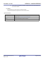
Figure 2-9. Add Section
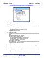
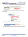
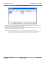
(2) Edit symbols
The [Symbol list] area displays the list of currently configured symbols.
When a symbol is selected from the list, detailed information on that symbol is displayed in the [Symbol detail]
area.
Edit the items in the [Symbol detail] area.
R20UT2142EJ0100 Rev.1.00
Sep 01, 2012
Page 17 of 620
CubeSuite+ V1.03.00
CHAPTER 2 FUNCTIONS
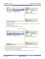
Figure 2-10. Segment Detail (When _tp_TEXT Is Selected)
Symbols can also be added.
Click [Add symbol] to add a new symbol "NewSymbol_XXX" directly below the row selected in the list (XXX: 0 to
255 in decimal numbers).
Edit the items in the [Symbol detail] area.
By default, [Type] is set to [TP symbol(%TP_SYMBOL)].
Figure 2-11. Add Symbol
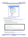
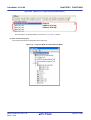
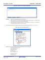
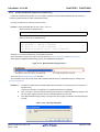
After editing the segments/sections and symbols, click the [Generate] button.
A link directive file (named project-name.dir) is generated based on the specified memory, segments, sections, and
symbol allocation information, and then added to the project.
The link directive file is generated in the project folder.
The link directive file that has been generated is also shown on the project tree, under the File node.
R20UT2142EJ0100 Rev.1.00
Sep 01, 2012
Page 18 of 620
CubeSuite+ V1.03.00
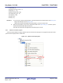
CHAPTER 2 FUNCTIONS
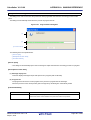
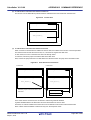
Figure 2-12. Project Tree Panel (After Generating Link Directive File)
Caution
The generated link directive file will be a build target.
If a link directive file has already been registered to the project, then the file will be removed from
the build target.
R20UT2142EJ0100 Rev.1.00
Sep 01, 2012
Page 19 of 620
CubeSuite+ V1.03.00
2.3.3
CHAPTER 2 FUNCTIONS
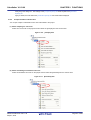
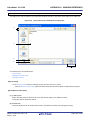
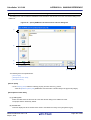
Add a file to a project
Files can be added to a project by the following methods.
- Adding an existing file
- Creating and adding an empty file
(1) Adding an existing file
(a) Add an individual files
Drag the file from Explorer or the like, and drop it onto the empty space below the project tree.
The file is added below the File node.
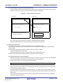
Figure 2-13. Project Tree Panel (File Drop Location)
Drop the file here
Caution
To add other than the standard startup routine, drop the file onto the Startup node.
See "2.3.1 Set a startup routine" for details about using other than the standard startup
routine.
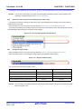
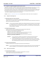
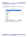
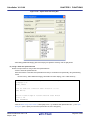
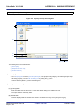
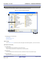
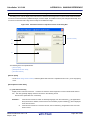
(b) Add a folder
Drag the folder from Explorer or the like, and drop it onto the empty space below the project tree. The Add
Folder and File dialog box will open.
Remark
You can also add multiple folders to the project at the same time by dragging multiple folders at
same time and dropping them onto the project tree.
Caution
When the folder with the name that is more than 200 characters is dropped, the folder is
added to the project tree as a category with the name that 201st character and after are
deleted.
R20UT2142EJ0100 Rev.1.00
Sep 01, 2012
Page 20 of 620
CubeSuite+ V1.03.00
CHAPTER 2 FUNCTIONS
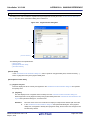
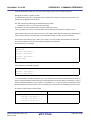
Figure 2-14. Add Folder and File Dialog Box
In the dialog box, select the types of the files to be added to the project and specify the number of levels of the
subfolder to be added to the project. And then click the [OK] button.
Remark
You can select multiple file types by left clicking while holding down the [Ctrl] or [Shift] key.
If nothing is selected, it is assumed that all types are selected.
The folder is added below the File node.
Note that on the project tree, the folder is the category.
Remark
When the category node created by the user exists, you can add a file below the node by dropping the
file onto the node (see "2.3.6 Classify a file into a category" for a category node).
R20UT2142EJ0100 Rev.1.00
Sep 01, 2012
Page 21 of 620
CubeSuite+ V1.03.00
CHAPTER 2 FUNCTIONS
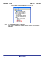
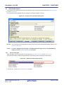
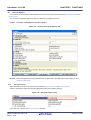
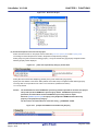
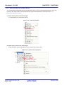
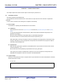
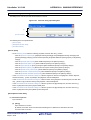
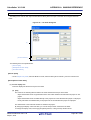
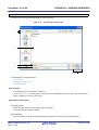
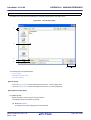
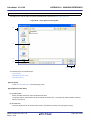
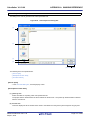
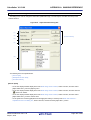
(2) Creating and adding an empty file
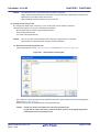
On the project tree, select either one of the Project node, Subproject node, or File node, and then select [Add] >>
[Add New File...] from the context menu. The Add File dialog box will open.
Figure 2-15. Add File Dialog Box
In the dialog box, specify the file to be created and then click the [OK] button.
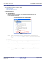
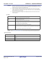
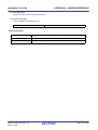
The file is added below the File node.
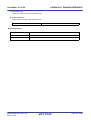
The project tree after adding the file and folder will look like the one below.
Figure 2-16. Project Tree Panel (After Adding File "main.c")
R20UT2142EJ0100 Rev.1.00
Sep 01, 2012
Page 22 of 620
CubeSuite+ V1.03.00
CHAPTER 2 FUNCTIONS
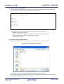
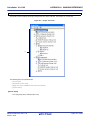
Figure 2-17. Project Tree Panel (After Adding Folder "src")
Remark
The location of the file added below the File node depends on the current file display order setting.
See "2.3.7 Change the file display order" for the method of changing the file display order.
Cautions 1.
If the paths differ, you can add source files with the same name.
Note, however, that if the setting of the output file name is left as the default, the output files will
have the same name, which will prevent the build from running correctly (for example, when
adding D:\sample1\func.c and D:\sample2\func.c, the default output file name for these files is
both func.obj).
To avoid this problems, set the output file name for each of those files to a different name with
the individual build options for the source files.
Changing the name of the C source file is made with the [Object module file name] property in
the [Output File] category from the [Individual Compile Options] tab.
Changing the name of the assembler source file is made with the [Object module file name]
property in the [Output File] category from the [Individual Assemble Options] tab.
See "2.11.2 Set build options at the file level" for how to set the individual build options.
2.
3.
If source files with the same name are added, the target file cannot opened during debugging.
If the file with the extension of "dr" or "dir" is added to the project, it is treated as the link
directive file.
It is also treated as the link directive file if it is added below the Startup node.
When adding the link directive file to the project, if the link directive file has already been added
then only the latest link directive file to be added is targeted by a build; any such files added
prior to this one will not be targeted.
When setting the link directive file that is not targeted by a build as the build target, if other link
directive files have also been added then the file will be targeted by the build, and the others will
not be targeted.
4.
Up to 5000 files can be added to the main project or subproject.
When a new file is added, an empty file is created in the location specified in the Add File dialog box.
By double clicking the file name on the project tree, you can open the Editor panel and edit the file.
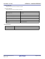
The files that can be opened with the Editor panel are shown below.
R20UT2142EJ0100 Rev.1.00
Sep 01, 2012
Page 23 of 620
CubeSuite+ V1.03.00
CHAPTER 2 FUNCTIONS
- C source file (*.c)
- Assembler source file (*.asm, *.s)
- Header file (*.h, *.inc)
- Symbol information file (*.sfg)
- Link directive file (*.dir, *.dr)
- Link map file (*.map)
- Hex file (*.hex)
- Text file (*.txt)
Remarks 1.
You can use one of the procedures below to open files other than those listed above in the Editor panel.
- Drag a file and drop it onto the Editor panel.
- Select a file and then select [Open with Internal Editor...] from the context menu.
2.
When the environment is set to use an external text editor on the Option dialog box, the file is opened
with the external text editor that has been set.
Other files are opened with the applications associated by the host OS.
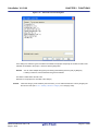
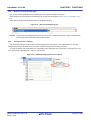
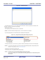
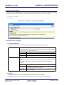
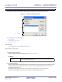
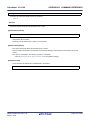
2.3.4
Remove a file from a project
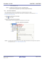
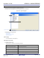
To remove the file added to a project, select the file to be removed from the project on the project tree and then select
[Remove from Project] from the context menu.
Figure 2-18. [Remove from Project] Item
R20UT2142EJ0100 Rev.1.00
Sep 01, 2012
Page 24 of 620
CubeSuite+ V1.03.00
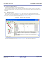
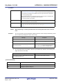
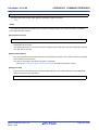
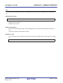
2.3.5
CHAPTER 2 FUNCTIONS
Remove a file from the build target
You can remove the specific file from the build target out of all the files added to the project.
Select the file to be removed from the build target on the project tree and select the [Build Settings] tab on the Property
panel.
Select [No] on the [Set as build-target] property in the [Build] category.
Figure 2-19. [Set as build-target] Property
Remark
The files that can be applied this function are C source files, assembler source files, object module files, link
directive files, symbol information files, and library files.
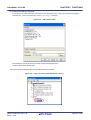
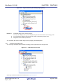
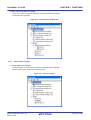
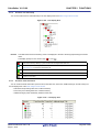
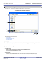
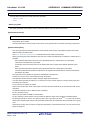
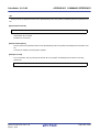
2.3.6
Classify a file into a category
You can create a category under the File node and classify files by the category. This makes it easier to view files
added to the project on the project tree, and makes it easier to manage files according to function.
To create a category node, select either one of the Project node, Subproject node, or File node on the project tree, and
then select [Add] >> [Add New File...] from the context menu.
Figure 2-20. [Add New Category] Item (For File Node)
R20UT2142EJ0100 Rev.1.00
Sep 01, 2012
Page 25 of 620
CubeSuite+ V1.03.00
CHAPTER 2 FUNCTIONS
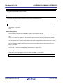
Figure 2-21. Project Tree Panel (After Adding Category Node)
Remarks 1.
The default category name is "New category".
To change the category name, you can use [Rename] from the context menu of the category node.
2.
You can also add a category node with the same name as the existing category node.
3.
Categories can be nested up to 20 levels.
You can classify files into the created category node by dragging and dropping the file.
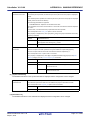
2.3.7
Change the file display order
You can change the display order of the files and category nodes by the buttons on the project tree.
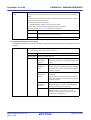
Figure 2-22. Toolbar (Project Tree Panel)
Select any of the buttons below on the toolbar of the Project Tree panel.
R20UT2142EJ0100 Rev.1.00
Sep 01, 2012
Page 26 of 620
CubeSuite+ V1.03.00
CHAPTER 2 FUNCTIONS
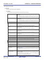
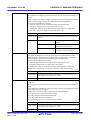
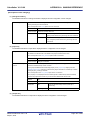
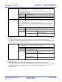
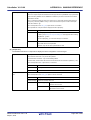
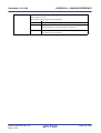
Button
Description
Sorts category nodes and files in order of their names.
: Ascending order
: Descending order
: Ascending order
Sorts category nodes and files in order of their timestamp.
: Descending order
: Ascending order
: Descending order
Displays category nodes and files in order of the user definition (default).
You can change the display order of category nodes and files arbitrarily by dragging and dropping them.
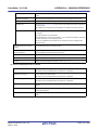
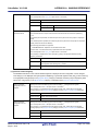
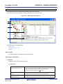
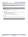
2.3.8
Update file dependencies
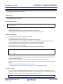
When you perform a change (changing include file paths, adding the include statement of the header file to the source
file, etc.) that effects the file dependencies in the compile option settings or assemble option settings, you must update
the dependencies of the relevant files.
Updating file dependencies is performed for the entire project (main project and subprojects) or active project.
(1) For the entire project
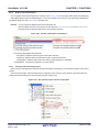
From the [Build] menu, select [Update Dependencies].
Figure 2-23. [Update Dependencies] Item
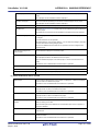
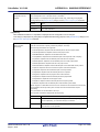
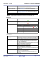
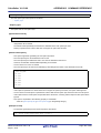
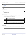
(2) For the active project
From the [Build] menu, select [Update Dependencies of active project].
R20UT2142EJ0100 Rev.1.00
Sep 01, 2012
Page 27 of 620
CubeSuite+ V1.03.00
CHAPTER 2 FUNCTIONS
Figure 2-24. [Update Dependencies of active project] Item
Remark
If there are files being edited with the Editor panel when updating file dependencies, then all these files are
saved.
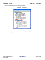
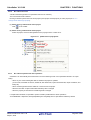
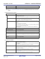
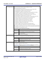
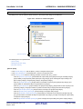
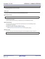
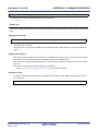
Dependency files (include files) can be displayed under the source file on the project tree.
Figure 2-25. Project Tree Panel (After Displaying Dependency File)
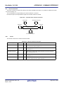
The display of the dependency files is updated on the following timings:
- When the first build is run after the project is loaded
- When
on the toolbar is clicked
- When [Update Dependencies] is selected from the [Build] menu
- When [Update Dependencies of active project] is selected from the [Build] menu
Remarks 1.
The display of dependency files is valid only when the [Show dependency files in project tree]
checkbox in the [General - Build/Debug] category of the Option dialog box is selected.
R20UT2142EJ0100 Rev.1.00
Sep 01, 2012
Page 28 of 620
CubeSuite+ V1.03.00
CHAPTER 2 FUNCTIONS
2.
Information on the dependency files displayed on the project tree is not saved in the project file.
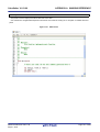
Cautions 1.
When checking for dependences on include files, CubeSuite+ does not support cases of
include files to which conditional statements such as #if apply or for which the #include
directive is commented out.
Therefore, there is a case where this product regards an include file unnecessary for a build as
a necessary file (In the example below, header1.h and header5.h are judged as required for
build).
#if
0
#include
"header1.h"
#else
#include
/* Dependence relationship judged to exist */
/* ! zero */
"header2.h"
/* Dependence relationship to exist */
#endif
#define
AAA
#ifdef
AAA
#include
"header3.h"
/* Dependence relationship to exist */
"header4.h"
/* Dependence relationship to exist */
"header5.h"
/* Dependence relationship judged to exist */
#else
#include
#endif
/*
#include
*/
2.
When checking for dependences on include files, CubeSuite+ does not support include
statements that follow comments or comment marks that are on the same line.
Therefore, there is a case where this product regards an include file necessary for a build as a
unnecessary file (In the example below, header6.h and header7.h are judged as no-required for
build).
/* comment */
to exist */
#include
"header6.h"
/* Dependence relationship judged not
/*
comment
*/ #include
to exist */
R20UT2142EJ0100 Rev.1.00
Sep 01, 2012
"header7.h"
/* Dependence relationship judged not
Page 29 of 620
CubeSuite+ V1.03.00
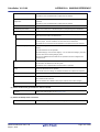
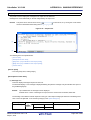
2.4
CHAPTER 2 FUNCTIONS
Set the Type of the Output File
Set the type of the file to be output as the product of the build.
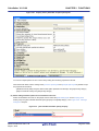
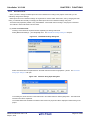
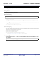
Select the build tool node on the project tree and select the [Common Options] tab on the Property panel.
Select the file type in the [Output file type] property in the [Output File Type and Path] category.
Figure 2-26. [Output file type] Property
(1) When [Execute Module(Load Module File)] is selected (Default)
The load module file (non-ROMized) and hex file are generated.
The load module file will be the debug target.
The ROMized load module file will be the debug target when [Yes] in the [Output ROMized load module file]
property in the [Output File] category from the [ROMize Options] tab category is selected.
(2) When [Execute Module(Non-ROMized Load Module File)] is selected
The load module file (non-ROMized), ROMized load module file and hex file are generated.
The load module file (non-ROMized) will be the debug target.
Remark
This item is displayed only when [Yes] in the [Output ROMized load module file] property and [Yes] in
the [Output Non-ROMized load module file] property in the [Output File] category from the [ROMize
Options] tab is selected.
(3) When [Execute Module(Hex File)] is selected
The load module file (non-ROMized) and hex file are generated.
The hex file will be the debug target.
Caution
2.4.1
For the library project, this property is always [Library] and cannot be changed.
Change the output file name
The names of the load module file, non-ROMized load module file, hex file, and library file output by the build tool are
set to the following names by default.
Load module file name: %ProjectName%.lmf
Non-ROMized load module file: %ProjectName%_NonROMize.lmf
Hex file name: %ProjectName%.hex
Library file name: lib%ProjectName%.lib
Remark
"%ProjectName%" is a placeholder. It is replaced with the project name.
The method to change these file names is shown below.
(1) When changing the load module file name and non-ROMized load module file name
Select the build tool node on the project tree and select the [Link Options] tab on the Property panel.
Enter the file name to be changed to in the [Output file name] property in the [Output File] category.
R20UT2142EJ0100 Rev.1.00
Sep 01, 2012
Page 30 of 620
CubeSuite+ V1.03.00
CHAPTER 2 FUNCTIONS
Figure 2-27. [Output file name] Property
This property supports the following placeholders.
%ActiveProjectName%: Replaces with the active project name.
%MainProjectName%: Replaces with the main project name.
%ProjectName%: Replaces with the project name.
The non-ROMized load module file name is the name specified in the [Output file name] property with string
"_NonROMize" added.
Remarks 1.
You can also change the option in the same way with the [Output file name] property in the
[Frequently Used Options(for Link)] category on the [Common Options] tab.
2.
If the target is a multi-core CPU, the load module for the common module and the load module for
core n are generated, and the final load module is then generated based on those (n: number of
cores of the target CPU).
Load module for the common module: input string without the extension _cmn.lmf
Load module for the core n: input string without the extension _pen.lmf
(2) When changing the hex file name
Select the build tool node on the project tree and select the [Hex Output Options] tab on the Property panel.
Enter the hex file name to be changed to on the [Hex file name] property in the [Output File] category.
Figure 2-28. [Hex file name] Property
This property supports the following placeholders.
%ActiveProjectName%: Replaces with the active project name.
%MainProjectName%: Replaces with the main project name.
%ProjectName%: Replaces with the project name.
(3) When changing the library file name
Select the build tool node on the project tree and select the [Create Library Options] tab on the Property panel.
Enter the library file name to be changed to on the [Output file name] property in the [Output File] category.
Figure 2-29. [Output file name] Property
This property supports the following placeholders.
%ActiveProjectName%: Replaces with the active project name.
R20UT2142EJ0100 Rev.1.00
Sep 01, 2012
Page 31 of 620
CubeSuite+ V1.03.00
CHAPTER 2 FUNCTIONS
%MainProjectName%: Replaces with the main project name.
%ProjectName%: Replaces with the project name.
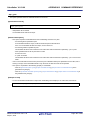
2.4.2
Output an assemble list
The assemble list (the code of the assemble result) is output to the assemble list file.
Select the build tool node on the project tree and select the [Compile Options] tab on the Property panel.
To output the assemble list file, select [Yes(-Xprn_path)] in the [Output assemble list file] property in the [Assemble List]
category.
Figure 2-30. [Output assemble list file] Property
When outputting the assemble list file, you can set the output folder and output file name.
(1) Set the output folder
Setting the output folder is made with the [Output folder for assemble list file] property by directly entering in the
text box or by the [...] button.
This property supports the following placeholder.
%BuildModeName%: Replaces with the build mode name.
"%BuildModeName%" is set by default.
The file name will be the source file name with the extension replaced by ".prn".
Remark
2.4.3
See "3.1 Assemble List File" for details about the assemble list file.
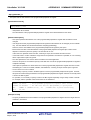
Output map information
The map information (the information of the link result) is output to the link map file.
Select the build tool node on the project tree and select the [Link Options] tab on the Property panel.
To output the link map file, select [Yes(-Xmap)] in the [Output link map file] property in the [Link Map] category.
Figure 2-31. [Output link map file] Property
When outputting the link map file, you can set the output folder and output file name.
(1) Set the output folder
Setting the output folder is made with the [Output folder for link map file] property by directly entering in the text box
or by the [...] button.
This property supports the following placeholder.
%BuildModeName%: Replaces with the build mode name.
"%BuildModeName%" is set by default.
R20UT2142EJ0100 Rev.1.00
Sep 01, 2012
Page 32 of 620
CubeSuite+ V1.03.00
CHAPTER 2 FUNCTIONS
(2) Set the output file name
Setting the output file is made with the [Link map file name] property by directly entering in the text box.
This property supports the following placeholders.
%ActiveProjectName%: Replaces with the active project name.
%MainProjectName%: Replaces with the main project name.
%ProjectName%: Replaces with the project name.
"%ProjectName%.map" is set by default.
Remark
2.4.4
See "3.2 Link Map File" for details about the link map file.
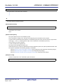
Output symbol information
The symbol information (the allocation section information of variables) is output to the symbol information file.
Select the build tool node on the project tree and select the [Link Options] tab on the Property panel.
To output the symbol information file, select [Yes(-Xsfg)] in the [Output symbol information file] property in the [Symbol
Information] category.
Select [Yes(-Xsfg_opt)] in the [Output optimized allocation information] property to output optimum allocation
information for variables at the section level.
Figure 2-32. [Output symbol information file] and [Output optimized allocation information] Property
When outputting the symbol information file, you can set the output folder and output file name.
(1) Set the output folder
Setting the output folder is made with the [Output folder for symbol information file] property by directly entering in
the text box or by the [...] button.
This property supports the following placeholder.
%BuildModeName%: Replaces with the build mode name.
"%BuildModeName%" is set by default.
(2) Set the output file name
Setting the output file is made with the [Symbol information file name] property by directly entering in the text box.
This property supports the following placeholders.
%ActiveProjectName%: Replaces with the active project name.
%MainProjectName%: Replaces with the main project name.
%ProjectName%: Replaces with the project name.
"%ProjectName%.sfg" is set by default.
Remark
See "3.3 Symbol Information File" for details about the symbol information file.
R20UT2142EJ0100 Rev.1.00
Sep 01, 2012
Page 33 of 620
CubeSuite+ V1.03.00
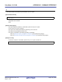
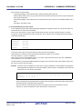
2.5
CHAPTER 2 FUNCTIONS
Set Compile Options
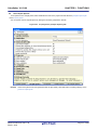
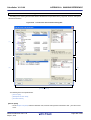
To set options for the compile phase, select the Build tool node on the project tree and select the [Compile Options] tab
on the Property panel.
You can set the various compile options by setting the necessary properties in this tab.
Figure 2-33. Property Panel: [Compile Options] Tab
Remark
Often used options have been gathered under the [Frequently Used Options(for Compile)] category on the
[Common Options] tab.
R20UT2142EJ0100 Rev.1.00
Sep 01, 2012
Page 34 of 620
CubeSuite+ V1.03.00
2.5.1
CHAPTER 2 FUNCTIONS
Perform optimization with the code size precedence
Select the build tool node on the project tree and select the [Compile Options] tab on the Property panel.
To perform optimization with the code size precedence, select [Code Size Precedence(-Osize)] in the [Optimization
Level] property in the [Optimization] category (default: [Default Optimization(-Odefault)]).
Figure 2-34. [Level of optimization] Property (Code Size Precedence)
Remarks 1.
You can also set the option in the same way with the [Optimization Level] property in the [Frequently
Used Options(for Compile)] category on the [Common Options] tab.
2.
2.5.2
See "B.1.5 Optimization function" for details about the optimization function.
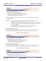
Perform optimization with the execution speed precedence
Select the build tool node on the project tree and select the [Compile Options] tab on the Property panel.
To perform optimization with the execution speed precedence, select [Speed Precedence(-Ospeed)] in the
[Optimization Level] property in the [Optimization] category (default: [Default Optimization(-Odefault)]).
Figure 2-35. [Level of optimization] Property (Execution Speed Precedence)
Remarks 1.
You can also set the option in the same way with the [Optimization Level] property in the [Frequently
Used Options(for Compile)] category on the [Common Options] tab.
2.
2.5.3
See "B.1.5 Optimization function" for details about the optimization function.
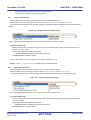
Add an include path
Select the build tool node on the project tree and select the [Compile Options] tab on the Property panel.
The include path setting is made with the [Additional include paths] property in the [Preprocess] category.
Figure 2-36. [Additional include paths] Property
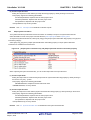
If you click the [...] button, the Path Edit dialog box will open.
R20UT2142EJ0100 Rev.1.00
Sep 01, 2012
Page 35 of 620
CubeSuite+ V1.03.00
CHAPTER 2 FUNCTIONS
Figure 2-37. Path Edit Dialog Box
Enter the include path per line in [Path(One path per one line)].
You can specify up to 259 characters per line, up to 256 lines.
Remarks 1.
This property supports placeholders.
If a line is double clicked in [Placeholder], the placeholder will be reflected in [Path(One path per one
line)].
2.
You can also specify the include path by one of the following procedures.
- Drag and drop the folder using such as Explorer.
- Click the [Browse...] button, and then select the folder in the Browse For Folder dialog box.
- Double click a row in [Placeholder].
3.
Select the [Subfolders are automatically included] check box before clicking the [Browse...] button to
add all paths under the specified one (down to 5 levels) to [Path(One path per one line)].
If you click the [OK] button, the entered include paths are displayed as subproperties.
Figure 2-38. [Additional include paths] Property (After Adding Include Paths)
To change the include paths, you can use the [...] button or enter the path directly in the text box of the subproperty.
When the include path is added to the project tree, the path is added to the top of the subproperties automatically.
R20UT2142EJ0100 Rev.1.00
Sep 01, 2012
Page 36 of 620
CubeSuite+ V1.03.00
Remark
CHAPTER 2 FUNCTIONS
You can also set the option in the same way with the [Additional include paths] property in the [Frequently
Used Options(for Compile)] category on the [Common Options] tab.
2.5.4
Set a macro definition
Select the build tool node on the project tree and select the [Compile Options] tab on the Property panel.
The macro definition setting is made with the [Macro definition] property in the [Preprocess] category.
Figure 2-39. [Macro definition] Property
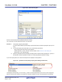
If you click the [...] button, the Text Edit dialog box will open.
Figure 2-40. Text Edit Dialog Box
Enter the macro definition in [Text] in the format of "macro name=defined value", with one macro name per line.
You can specify up to 256 characters per line, up to 256 lines.
The "=defined value" part can be omitted, and in this case, "1" is used as the defined value.
If you click the [OK] button, the entered macro definitions are displayed as subproperties.
Figure 2-41. [Macro definition] Property (After Setting Macros)
R20UT2142EJ0100 Rev.1.00
Sep 01, 2012
Page 37 of 620
CubeSuite+ V1.03.00
CHAPTER 2 FUNCTIONS
To change the macro definitions, you can use the [...] button or enter the path directly in the text box of the subproperty.
Remark
You can also set the option in the same way with the [Macro definition] property in the [Frequently Used
Options(for Compile)] category on the [Common Options] tab.
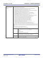
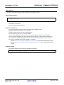
2.5.5
Reduce the code size (perform prologue/epilogue runtime calls)
It is possible to reduce the code size by performing a part of prologue/epilogue processing of the function based on
runtime library function calls.
Select the build tool node on the project tree and select the [Compile Options] tab on the Property panel.
To perform prologue/epilogue processing of the function based on runtime library function calls, select [Yes] in the [Use
prologue/epilogue library] property in the [Output Code] category.
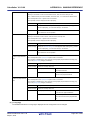
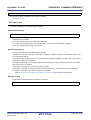
Figure 2-42. [Use prologue/epilogue library] Property
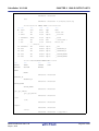
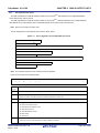
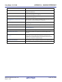
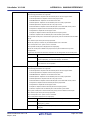
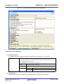
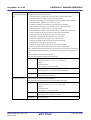
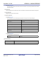
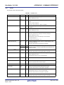
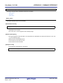
2.5.6
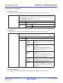
Change the register mode
Select the build tool node on the project tree and select the [Common Options] tab on the Property panel.
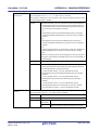
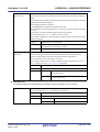
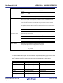
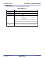
Select the register mode to on the [Register mode] property in the [Register Mode] category.
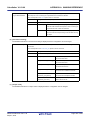
Figure 2-43. [Register mode] Property
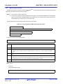
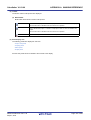
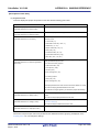
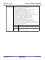
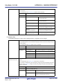
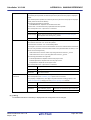
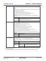
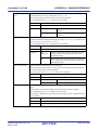
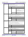
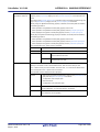
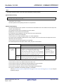
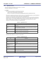
You can select from the following register modes.
Register Mode
Working Registers
Registers for Register Variables
32-register mode(None) (default)
r10 to r19
r20 to r29
26-register mode(-Xreg_mode=26)
r10 to r16
r23 to r29
22-register mode(-Xreg_mode=22)
r10 to r14
r25 to r29
Universal register mode(-Xreg_mode=common)
r10 to r14
r25 to r29
Remark
See "CubeSuite+ Integrated Development Environment User’s Manual: Coding for CX Compiler" for details
about the register mode.
R20UT2142EJ0100 Rev.1.00
Sep 01, 2012
Page 38 of 620
CubeSuite+ V1.03.00
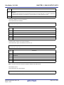
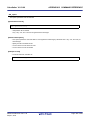
2.6
CHAPTER 2 FUNCTIONS
Set Assemble Options
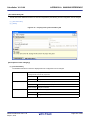
To set options for the assemble phase, select the Build tool node on the project tree and select the [Assemble Options]
tab on the Property panel.
You can set the various assemble options by setting the necessary properties in this tab.
Figure 2-44. Property Panel: [Assemble Options] Tab
Remark
Often used options have been gathered under the [Frequently Used Options(for Assemble)] category on the
[Common Options] tab.
Caution
This tab is displayed only when [No] in the [Build simultaneously] property in the [Build Method]
category from the [Common Options] tab is selected.
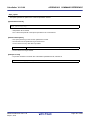
2.6.1
Add an include path
Select the build tool node on the project tree and select the [Assemble Options] tab on the Property panel.
The include path setting is made with the [Additional include paths] property in the [Preprocess] category.
Figure 2-45. [Additional include paths] Property
If you click the [...] button, the Path Edit dialog box will open.
R20UT2142EJ0100 Rev.1.00
Sep 01, 2012
Page 39 of 620
CubeSuite+ V1.03.00
CHAPTER 2 FUNCTIONS
Figure 2-46. Path Edit Dialog Box
Enter the include path per line in [Path(One path per one line)].
You can specify up to 259 characters per line, up to 256 lines.
Remarks 1.
This property supports placeholders.
If a line is double clicked in [Placeholder], the placeholder will be reflected in [Path(One path per one
line)].
2.
You can also specify the include path by one of the following procedures.
- Drag and drop the folder using such as Explorer.
- Click the [Browse...] button, and then select the folder in the Browse For Folder dialog box.
- Double click a row in [Placeholder].
3.
Select the [Subfolders are automatically included] check box before clicking the [Browse...] button to
add all paths under the specified one (down to 5 levels) to [Path(One path per one line)].
If you click the [OK] button, the entered include paths are displayed as subproperties.
Figure 2-47. [Additional include paths] Property (After Adding Include Paths)
To change the include paths, you can use the [...] button or enter the path directly in the text box of the subproperty.
When the include path is added to the project tree, the path is added to the top of the subproperties automatically.
R20UT2142EJ0100 Rev.1.00
Sep 01, 2012
Page 40 of 620
CubeSuite+ V1.03.00
Remark
CHAPTER 2 FUNCTIONS
You can also set the option in the same way with the [Additional include paths] property in the [Frequently
Used Options(for Assemble)] category on the [Common Options] tab.
2.6.2
Set a macro definition
Select the build tool node on the project tree and select the [Assemble Options] tab on the Property panel.
The macro definition setting is made with the [Macro definition] property in the [Preprocess] category.
Figure 2-48. [Macro definition] Property
If you click the [...] button, the Text Edit dialog box will open.
Figure 2-49. Text Edit Dialog Box
Enter the macro definition in [Text] in the format of "macro name=defined value", with one macro name per line.
You can specify up to 256 characters per line, up to 256 lines.
The "=defined value" part can be omitted, and in this case, "1" is used as the defined value.
If you click the [OK] button, the entered macro definitions are displayed as subproperties.
Figure 2-50. [Macro definition] Property (After Setting Macros)
R20UT2142EJ0100 Rev.1.00
Sep 01, 2012
Page 41 of 620
CubeSuite+ V1.03.00
CHAPTER 2 FUNCTIONS
To change the macro definitions, you can use the [...] button or enter the path directly in the text box of the subproperty.
Remark
You can also set the option in the same way with the [Macro definition] property in the [Frequently Used
Options(for Assemble)] category on the [Common Options] tab.
R20UT2142EJ0100 Rev.1.00
Sep 01, 2012
Page 42 of 620
CubeSuite+ V1.03.00
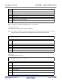
2.7
CHAPTER 2 FUNCTIONS
Set Link Options
To set options for the link phase, select the Build tool node on the project tree and select the [Link Options] tab on the
Property panel.
You can set the various link options by setting the necessary properties in this tab.
Caution
This tab is not displayed for the library project.
Figure 2-51. Property Panel: [Link Options] Tab
Remark
Often used options have been gathered under the [Frequently Used Options(for Link)] category on the
[Common Options] tab.
2.7.1
Add a user library
Select the build tool node on the project tree and select the [Link Options] tab on the Property panel.
Adding a user library is made with the [Using libraries] property in the [Library] category.
Figure 2-52. [Using libraries] Property
If you click the [...] button, the Text Edit dialog box will open.
R20UT2142EJ0100 Rev.1.00
Sep 01, 2012
Page 43 of 620
CubeSuite+ V1.03.00
CHAPTER 2 FUNCTIONS
Figure 2-53. Text Edit Dialog Box
In the [Text], specify only the "xxx" part of library file name "libxxx.lib" or "libxxx.a" (example: if you specify "user",
"libuser.lib" or "libuser.a" is assumed to be specified).
Add one item in one line.
You can specify up to 249 characters per line, up to 256 lines.
Remark
libxxx.lib is searched with higher priority. If it is not found, libxxx.a is searched.
If you click the [OK] button, the entered library files are displayed as subproperties.
Figure 2-54. [Using libraries] Property (After Setting Library Files)
To change the library files, you can use the [...] button or enter the path directly in the text box of the subproperty.
Remark
You can also set the option in the same way with the [Using libraries] property in the [Frequently Used
Options(for Link)] category on the [Common Options] tab.
The library file is searched from the library path.
To add a library path, set the [Additional library paths] property.
Caution
The library file can also be linked by adding it directly to the project.
In this case, the library file is not searched from the library path because it is linked directly via the
absolute path.
R20UT2142EJ0100 Rev.1.00
Sep 01, 2012
Page 44 of 620
CubeSuite+ V1.03.00
2.8
CHAPTER 2 FUNCTIONS
Set ROMize Options
To set options for the ROMize phase, select the Build tool node on the project tree and select the [ROMize Options] tab
on the Property panel.
You can set the various ROMize options by setting the necessary properties in this tab.
Caution
This tab is not displayed for the library project.
Figure 2-55. Property Panel: [ROMize Options] Tab
2.8.1
Create a ROMized load module
The following procedure shows how to create a ROMized load module using the ROMization area reservation code file
(rompcrt.obj) that is provided by default.
The ROMization processor is a tool that takes initial value information for variables in data-attribute sections as well as
programs allocated to RAM and packs them into a single section.
By default, this section becomes the "rompsec section".
By allocating the rompsec section to ROM and calling the copy function, it is possible to deploy initial value information
and programs into RAM.
Remark
See "CubeSuite+ Integrated Development Environment User’s Manual: Coding for CX Compiler" for details
about how to create the ROMized load module.
(1) Call a copy function
Call a copy function within the startup routine.
You can use the standard startup routine (cstart.obj) as-is, because it already contains a call to "_rcopy".
If you use "_rcopy2" or "_rcopy4" instead of "_rcopy" or specify the section to be copied, customize the standard
startup routine.
Remarks 1.
See "CubeSuite+ Integrated Development Environment User’s Manual: Coding for CX Compiler"
for details about copy functions.
2.
To use other than the standard startup routine, add the file to be used to the Startup node on the
project tree.
See "2.3.1 Set a startup routine" for details about the setting of the startup routine.
R20UT2142EJ0100 Rev.1.00
Sep 01, 2012
Page 45 of 620
CubeSuite+ V1.03.00
CHAPTER 2 FUNCTIONS
(2) Set ROMize options
Specify to generate the ROMized load module by the ROMize option.
Select the build tool node on the project tree and select the [ROMize Options] tab on the Property panel.
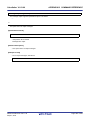
(a) Set the output of the ROMized load module file
Select [Yes] in the [Output ROMized load module file] property in the [Output File] category.
Figure 2-56. [Output ROMized load module file] Property
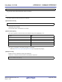
(b) Set using the standard ROMization area reservation code file
Select [Yes] (default) in the [Use standard ROMization area reservation code file] property in the [Input file]
category.
Figure 2-57. [Use standard ROMization area reservation code file] Property
(3) Run a build
Run a build to generate the ROMization load module file.
At this time, files are linked according to the following sequence.
- Object module file of the startup routine (cstart.obj)
- Library file that stores copy functions (libc.lib)
- ROMization area reservation code file (rompcrt.obj)
Remark
The ROMization area reservation code file should be linked last.
However, if [Yes(-Xrescan)] in the [Rescan library files] property in the [Others] category on the [Link
Options] tab is specified, the library file is linked after the ROMization area reservation code file, and an
error may be output during ROMization processing.
In such a case, explicitly secure the rompsec section area.
See "CubeSuite+ Integrated Development Environment User’s Manual: Coding for CX Compiler" for
details.
This product performs hex output processing after ROMization processing. Therefore, a hex file is also generated.
Load the generated hex file to the target using a ROM writer.
R20UT2142EJ0100 Rev.1.00
Sep 01, 2012
Page 46 of 620
CubeSuite+ V1.03.00
2.9
CHAPTER 2 FUNCTIONS
Set Hex Output Options
To set options for the hex output phase, select the Build tool node on the project tree and select the [Hex Output
Options] tab on the Property panel.
You can set the various hex output options by setting the necessary properties in this tab.
Caution
This tab is not displayed for the library project.
Figure 2-58. Property Panel: [Hex Output Options] Tab
Remark
Often used options have been gathered under the [Frequently Used Options(for Hex Output)] category on
the [Common Options] tab.
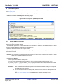
2.9.1
Set the output of a hex file
A hex file is generated by default after generating the ROMized load module.
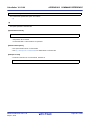
Select the build tool node on the project tree and select the [Hex Output Options] tab on the Property panel.
The setting to output a hex file is made with the [Output File] category.
Figure 2-59. [Output File] Category
(1) Set the output folder
Setting the output folder is made with the [Output folder for hex file] property by directly entering in the text box or
by the [...] button.
Up to 247 characters can be specified in the text box.
This property supports the following placeholder.
%BuildModeName%: Replaces with the build mode name.
"%BuildModeName%" is set by default.
R20UT2142EJ0100 Rev.1.00
Sep 01, 2012
Page 47 of 620
CubeSuite+ V1.03.00
CHAPTER 2 FUNCTIONS
(2) Set the output file name
Setting the output file is made with the [Hex file name] property by directly entering in the text box.
Up to 259 characters can be specified in the text box.
This property supports the following placeholders.
%ActiveProjectName%: Replaces with the active project name.
%MainProjectName%: Replaces with the main project name.
%ProjectName%: Replaces with the project name.
"%ProjectName%.hex" is set by default.
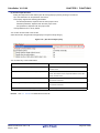
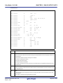
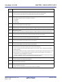
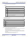
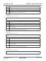
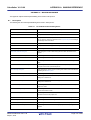
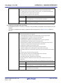
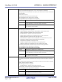
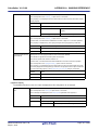
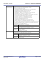
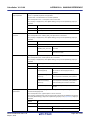
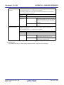
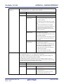
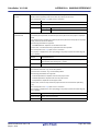
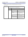
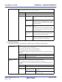
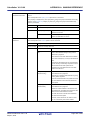
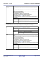
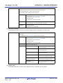
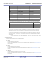
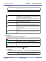
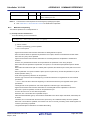
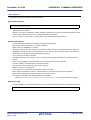
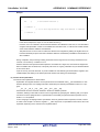
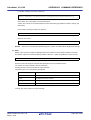
You can also set the format of the hex file.
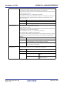
Select the format in the [Hex file format] property in the [Hex Format] category.
Figure 2-60. [Hex file format] Property
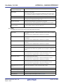
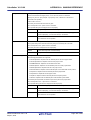
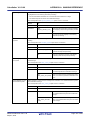
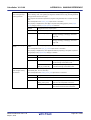
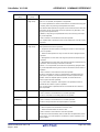
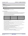
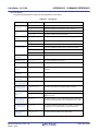
You can select any of the formats below.
Format
Intel expanded hex format(-Xhex_format=I)
Configuration
Start address record, expanded address record, data record,
and end record
Intel expanded hex format(32-bit address)(None)
Start linear address record, expanded linear start address
record, start address record, expanded address record, data
record, and end record
Motorola S type format(standard address)(-Xhex_format=S)
S0 record as a header record, S2 record as data record, and
S8 record as end record
Motorola S type format(32-bit address)(-Xhex_format=s)
S0 record as a header record, S3 record as data record, and
S7 record as end record
Expanded Tektronix hex format(-Xhex_format=T)
Remark
Data block, symbol block, and termination block
See "3.4 Hex File" for details about the hex file.
R20UT2142EJ0100 Rev.1.00
Sep 01, 2012
Page 48 of 620
CubeSuite+ V1.03.00
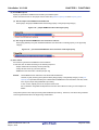
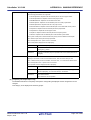
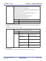
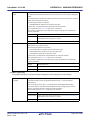
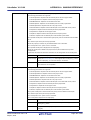
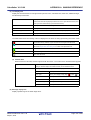
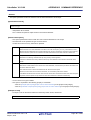
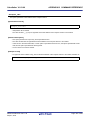
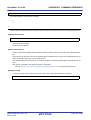
2.9.2
CHAPTER 2 FUNCTIONS
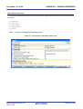
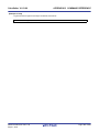
Fill the vacant area
Select the build tool node on the project tree and select the [Hex Output Options] tab on the Property panel.
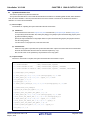
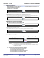
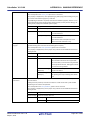
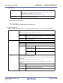
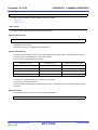
The setting to fill the vacant area is made with the [Hex Format] category.
If you select [Yes(-Xhex_fill)] in the [Specify converted address range] property, the [Filling value] property is displayed.
Figure 2-61. [Specify converted address range] and [Filling value] Property
Enter the fill value for the vacant area directly in the text box.
The range that can be specified for the value is 00 to FFFF (2- or 4-digit hexadecimal number).
"FFFF" is set by default.
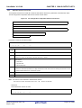
Set the address range of the area to be converted to a hex file in the [Start address] property and [Size] property.
The range that can be specified is 0 to FFFFFFFF (hexadecimal number) for the [Start address] property, and 1 to
100000000 (hexadecimal number) for the [Size] property.
Both are blank by default, so specify both values.
If either of them is blank, all the codes in the internal ROM area defined by the device file are converted into the hex
format.
R20UT2142EJ0100 Rev.1.00
Sep 01, 2012
Page 49 of 620
CubeSuite+ V1.03.00
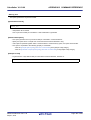
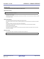
2.10
CHAPTER 2 FUNCTIONS
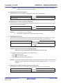
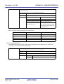
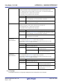
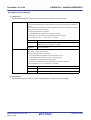
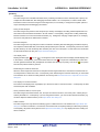
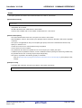
Set Create Library Options
To set options for the librarian, select the Build tool node on the project tree and select the [Create Library Options] tab
on the Property panel.
You can set the various create library options by setting the necessary properties in this tab.
Caution
This tab is displayed for the library project.
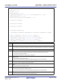
Figure 2-62. Property Panel: [Create Library Options] Tab
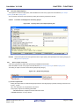
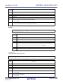
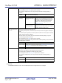
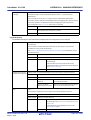
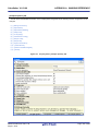
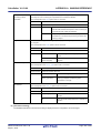
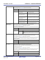
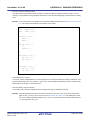
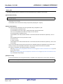
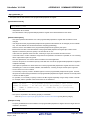
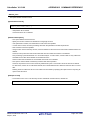
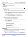
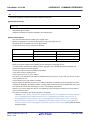
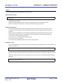
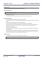
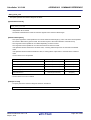
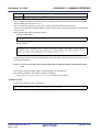
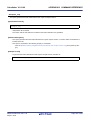
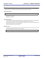
2.10.1
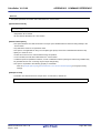
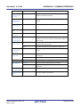
Set the output of a library file
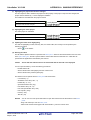
Select the build tool node on the project tree and select the [Create Library Options] tab on the Property panel.
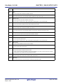
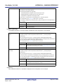
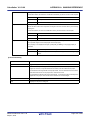
The setting to output a library file is made with the [Output File] category.
Figure 2-63. [Output File] Category
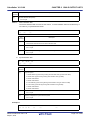
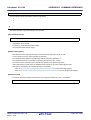
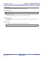
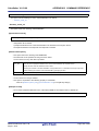
(1) Set the output folder
Setting the output folder is made with the [Output folder] property by directly entering to the text box or by the [...]
button.
Up to 247 characters can be specified in the text box.
This property supports the following placeholder.
%BuildModeName%: Replaces with the build mode name.
"%BuildModeName%" is set by default.
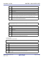
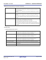
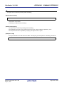
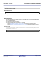
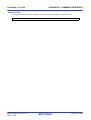
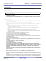
(2) Set the output file name
Setting the output file is made with the [Output file name] property by directly entering to the text box.
Up to 259 characters can be specified in the text box.
This property supports the following placeholders.
%ActiveProjectName%: Replaces with the active project name.
%MainProjectName%: Replaces with the main project name.
%ProjectName%: Replaces with the project name.
"lib%ProjectName%.lib" is set by default.
R20UT2142EJ0100 Rev.1.00
Sep 01, 2012
Page 50 of 620
CubeSuite+ V1.03.00
2.11
CHAPTER 2 FUNCTIONS
Set Build Options Separately
Build options are set at the project or file level.
Project level: See "2.11.1 Set build options at the project level"
File level: See "2.11.2 Set build options at the file level"
2.11.1
Set build options at the project level
To set options for build options for the project (main project or subproject), select the Build tool node on the project tree
to display the Property panel.
Select the phase tab and set build options by setting the necessary properties.
Compile phase: [Compile Options] tab
Assemble phase: [Assemble Options] tab
Link phase: [Link Options] tab
ROMize phase: [ROMize Options] tab
Hex output phase: [Hex Output Options] tab
Create library phase: [Create Library Options] tab
2.11.2
Set build options at the file level
You can individually set compile and assemble options for each source file added to the project.
(1) When setting compile options for a C source file
Select the C source file on the project tree and select the [Build Settings] tab on the Property panel.
Select [Yes] in the [Set individual compile option] property in the [Build] category. The "Figure 2-65. Message
Dialog Box" will open.
Figure 2-64. [Set individual compile option] Property
Figure 2-65. Message Dialog Box
Click [Yes] in the dialog box. The [Individual Compile Options] tab will be displayed.
R20UT2142EJ0100 Rev.1.00
Sep 01, 2012
Page 51 of 620
CubeSuite+ V1.03.00
CHAPTER 2 FUNCTIONS
Figure 2-66. Property Panel: [Individual Compile Options] Tab
You can set compile options for the C source file by setting the necessary properties in this tab.
Note that this tab takes over the settings of the [Common Options] tab and [Compile Options] tab by default except
the properties shown below.
- [Additional include paths] and [Use whole include paths specified for build tool] in the [Preprocess] category
- [Object module file name] in the [Output File] category
(2) When setting assemble options for an assembler source file
Select the assembler source file on the project tree and select the [Build Settings] tab on the Property panel.
Select [Yes] in the [Set individual assemble option] property in the [Build] category. The "Figure 2-68. Message
Dialog Box" will open.
Figure 2-67. [Set individual assemble option] Property
R20UT2142EJ0100 Rev.1.00
Sep 01, 2012
Page 52 of 620
CubeSuite+ V1.03.00
CHAPTER 2 FUNCTIONS
Figure 2-68. Message Dialog Box
Click [Yes] in the dialog box. The [Individual Assemble Options] tab will be displayed.
Figure 2-69. Property Panel: [Individual Assemble Options] Tab
You can set assemble options for the assembler source file by setting the necessary properties in this tab.
Note that this tab takes over the settings of the [Common Options] tab and [Compile Options] tab/[Assemble
Options] tab by default except the properties shown below.
- [Additional include paths] and [Use whole include paths specified for build tool] in the [Preprocess] category
- [Object module file name] in the [Output File] category
R20UT2142EJ0100 Rev.1.00
Sep 01, 2012
Page 53 of 620
CubeSuite+ V1.03.00
2.12
CHAPTER 2 FUNCTIONS
Prepare for Implementing Boot-Flash Relink Function
Depending on the system, in addition to the area which cannot be rewritten/replaced (boot area), there are occasions
when you can use the area which can be rewritten/replaced (flash area), such as the flash or external ROM.
In these kinds of systems, when you wish to change the program in the flash area, a function called the "relink function"
correctly performs function calls between the boot area and flash area without rebuilding the program in the boot area.
By creating load module files for the boot area and flash area, you can implement the relink function.
The method to implement the relink function is shown below.
Remark
2.12.1
See "B.1.6 Boot-flash re-link function" for details about the relink function and how to implement it.
Prepare the build target files
(1) Specify the $ext_func control instruction
Describe the $ext_func control instruction in the source file for the boot area.
With the $ext_func control instruction, specify the ID value for the target function (the actual function exists in the
flash area and is called from the boot area).
Remark
In order to prevent description mistakes and inconsistencies between source files, it is recommend that
you organize the $ext_func control instruction in a single file, and regardless of the boot area or flash
area, include that file in all source files by using the $ext_func control instruction (or #include directive
when describing in C language).
(2) Prepare the startup routines
Prepare the startup routines for the projects for both the boot area and flash area.
Each startup routine must perform the following processing.
- Setting tp, gp, and ep values in the boot area
- Calling the _rcopy function to initialize the RAM area to be used for the boot area
- Branching from the boot area to the startup routine of the flash area
- Calling the _rcopy function to initialize the RAM area to be used for the flash area
- Moving to the processing of the flash area
Remarks 1.
If tp, gp, and ep are not used in the boot area, the values may be set in the flash area.
If ROMization processing is not performed, the _rcopy function call is not required.
2.
Use the same address values in the boot area and flash area for the tp, gp, and ep values.
These values may be different, but in this case the values must be set each time control has
been transferred between an instruction code in the boot area and one in the flash area.
(3) Prepare the link directive files
Prepare link directive files for the projects for both the boot area and flash area.
Remark
You can use the same link directive file with the boot area and flash area, but since the description will
become complicated, it is recommended that the separate link directive file for each area is used.
2.12.2
Set the boot area project
(1) Create the boot area project
Create the project for the boot area and add the build target files to the project.
Add the startup routine directly below the Startup node.
R20UT2142EJ0100 Rev.1.00
Sep 01, 2012
Page 54 of 620
CubeSuite+ V1.03.00
CHAPTER 2 FUNCTIONS
Figure 2-70. Boot Area Project
(2) Set the build options for the boot area project
Select the build tool node on the project tree and select the [Common Options] tab on the Property panel.
The settings for the build options are made in the [Flash Correspondence] category.
Select [Yes] in the [Use boot-flash re-linking] property. The [Load module file type] property and [Branch table
address] property will be displayed.
Figure 2-71. [Flash Correspondence] Category in Boot Area
Select [Boot area load module file(None)] (default) in the [Load module file type] property.
Specify the start address of the branch table (address in the flash area) in the [Branch table address] property.
The range that can be specified for the value is 0 to FFFFFFFF (hexadecimal number).
"0" is set by default.
Caution
The load module file before ROMization processing must be specified for the flash area project.
This product performs ROMization processing by default. If ROMization processing is
performed, the load module file before ROMization processing must be output.
Select the [ROMize Options] tab and [Yes] in the [Output Non-ROMized load module file]
property in the [Output File] category.
The file name is the load module file name with string "_NonROMize" added.
Figure 2-72. [Output Non-ROMized load module file] Property
R20UT2142EJ0100 Rev.1.00
Sep 01, 2012
Page 55 of 620
CubeSuite+ V1.03.00
CHAPTER 2 FUNCTIONS
(3) Run a build of the boot area project
When you run a build of the boot area project, the load module file is generated.
The hex file is also generated.
Figure 2-73. Generated Files for Boot Area
2.12.3
Set the flash area project
(1) Create the flash area project
Create the project for the boot area and add the build target files to the project.
Add the startup routine directly below the Startup node.
Figure 2-74. Flash Area Project
R20UT2142EJ0100 Rev.1.00
Sep 01, 2012
Page 56 of 620
CubeSuite+ V1.03.00
CHAPTER 2 FUNCTIONS
(2) Set the build options for the flash area project
Select the build tool node on the project tree and select the [Common Options] tab on the Property panel.
The settings for the build options are made in the [Flash Correspondence] category.
Select [Yes] in the [Use boot-flash re-linking] property. The [Load module file type] property and [Branch table
address] property will be displayed.
Figure 2-75. [Flash Correspondence] Category in Flash Area
Select [Flash area load module file(-Xflash)] in the [Load module file type] property. The [Boot area load module
file name] property will be displayed.
Specify the load module file for the boot area.
Caution
Specify the load module file before ROMization processing in this property.
An error will occur if the load module file after ROMization processing is specified.
Specify the start address of the branch table (same as the address specified in the boot area project) in the
[Branch table address] property.
(3) Run a build of the flash area project
When you run a build of the flash area project, the load module file which implements the re-link function is
created.
The boot area hex file (the same content as the file generated in "2.12.2 Set the boot area project") and flash area
hex file are also generated.
Figure 2-76. Generated Files for Flash Area
R20UT2142EJ0100 Rev.1.00
Sep 01, 2012
Page 57 of 620
CubeSuite+ V1.03.00
2.13
CHAPTER 2 FUNCTIONS
Allocate Variables to Optimum Section
To allocate the variables to the optimum section, the symbol information file (a text-format file that allocation
information for the variable defined in the C source file is described) can be used.
The variables can be allocated to the optimum section without editing the C source file by generating the symbol
information file and referencing the file when compiling.
The procedures for performing this operation are described below.
- Generating the symbol information file automatically and relocating the variables
- Editing and using the auto-generated symbol information file
Confirm that the build has completed successfully and the load module file has been generated before using this
function.
Remark
See "B.1.4 Symbol information file" for detail about the symbol information file.
(1) Generating the symbol information file automatically and relocating the variables
Below is the procedure for generating the symbol information file automatically and referring that file to allocate the
variables, via one build.
(a) Set the generation of the symbol information file
Select the build tool node on the project tree and select the [Link Options] tab on the Property panel.
Select [Yes(-Xsfg)] in the [Output symbol information file] property in the [Symbol Information] category. The
empty symbol information file will be generated and added to the project (it will be also shown in the Files node
of the project tree).
The output destination is the file set in the [Output folder for symbol information file] property and [Symbol
information file name] property.
Select [Yes(-Xsfg_opt)] in the [Output optimized allocation information] property.
Remark
If a symbol information file with the same name already exists, the build will be configured to use it.
Figure 2-77. [Output symbol information file] and [Output optimized allocation information] Property
R20UT2142EJ0100 Rev.1.00
Sep 01, 2012
Page 58 of 620
CubeSuite+ V1.03.00
CHAPTER 2 FUNCTIONS
Figure 2-78. Project Tree Panel (After Generating Symbol Information File)
The settings of the output folder and file of the symbol information file are can be changed.
<1> Set the output folder
Setting the output folder is made with the [Output folder for symbol information file] property by directly
entering in the text box or by the [...] button.
Up to 247 characters can be specified in the text box.
This property supports the following placeholder.
%BuildModeName%: Replaces with the build mode name.
"%BuildModeName%" is set by default.
<2> Set the output file name
Setting the output file is made with the [Symbol information file name] property by directly entering in the
text box.
Up to 259 characters can be specified in the text box.
This property supports the following placeholders.
%ActiveProjectName%: Replaces with the active project name.
%MainProjectName%: Replaces with the main project name.
%ProjectName%: Replaces with the project name.
"%ProjectName%.sfg" is set by default.
If this property is changed, the empty symbol information file is generated and added to the project (it will
be also shown in the Files node of the project tree).
(b) Run a build of the project
Run a build of the project.
The symbol information file is generated. And then it is inputted into CX automatically and a rebuild is
executed again.
Remarks 1.
The symbol information file in "(a) Set the generation of the symbol information file" is
overwritten by running a build.
2.
Since the objects are generated anew using the symbol information file, the second build will
be a rebuild.
R20UT2142EJ0100 Rev.1.00
Sep 01, 2012
Page 59 of 620
CubeSuite+ V1.03.00
CHAPTER 2 FUNCTIONS
If the build completes successfully, the load module file is generated with the variables allocated.
Figure 2-79. Project Tree Panel (After Generating Load Module File)
(2) Editing and using the auto-generated symbol information file
Users can edit the symbol information file.
Below is the procedure for editing the generated symbol information file in "(1) Generating the symbol information
file automatically and relocating the variables" by the user and referring that file to allocate variables.
(a) Editing the symbol information file
Edit the symbol information file generated automatically in "(1) Generating the symbol information file
automatically and relocating the variables".
Describe the symbol information file according to the following format.
Describe the variables in the order of priority, from highest use frequency.
[tidata.byte]:Size_section-sizebytes
[tidata.word]:Size_section-sizebytes
[sidata]:Size_section-sizebytes
[sedata]:Size_section-sizebytes
[sdata]:Size_section-sizebytes
global-variable,reference-count,byte-size
static-variable-in-file, reference-count,byte-size,file-name-including-path
static-variable-in-function,reference-count,byte-size,file-name-includingpath,function-name
Remark
See "3.3 Symbol Information File" for detail about the format of the symbol information file.
(b) Set the generation of the symbol information file
Select the build tool node on the project tree and select the [Link Options] tab on the Property panel.
Select [No] in the [Output symbol information file] property.
R20UT2142EJ0100 Rev.1.00
Sep 01, 2012
Page 60 of 620
CubeSuite+ V1.03.00
CHAPTER 2 FUNCTIONS
Figure 2-80. [Output symbol information file] Property
(c) Run a build of the project
Run a build of the project.
The load module file is generated with the variables allocated according to the specified contents in the symbol
information file.
Caution
If the file with the extension of "sfg" is added to the project, it is treated as a symbol information file.
It is also treated as a symbol information file if it is added below the Startup node.
When adding a symbol information file to the project, if a symbol information file has already been
added, then only the latest symbol information file to be added is targeted by a build; any such files
added prior to this one will not be targeted.
When setting the symbol information file that is not targeted by a build as a build target, if other
symbol information files have also been added then the file will be targeted by the build, and the
others will not be targeted.
R20UT2142EJ0100 Rev.1.00
Sep 01, 2012
Page 61 of 620
CubeSuite+ V1.03.00
2.14
CHAPTER 2 FUNCTIONS
Create a Multi-Core Load Module
This product is able to create a single load module from a program that runs on multiple cores (multi-core).
The procedures for performing this operation are described below.
Remark
See "CubeSuite+ Integrated Development Environment User’s Manual: Coding for CX Compiler" for details
about multi-core programming.
(1) Create a link directive file
The link directive file must be created together with each target system.
Create the file with reference to the sample link directive file below.
product install folder\CubeSuite+\CX\Vx.xx\smp\850\multi_smp.dir
(2) Create a project
Create a project and add build target files (source file, link directive file, etc.) to the project.
Figure 2-81. Project for Multi-Core
Remark
To use other than the standard startup routine, add the file to the Startup node (see "2.3.1 Set a startup
routine").
(3) Set build options
(a) Set core files
Select each core file on the project tree and select the [Build Settings] tab on the Property panel.
Select the corresponding core number ([Core n (-Xmulti=pen)]) in the [Target core number] property in the
[Multi-Core] category (n: number of cores on the target CPU).
Figure 2-82. [Target core number] Property
R20UT2142EJ0100 Rev.1.00
Sep 01, 2012
Page 62 of 620
CubeSuite+ V1.03.00
CHAPTER 2 FUNCTIONS
The icon of the file specifying the core number changes to an icon with the core number added.
Figure 2-83. Project for Multi-Core (After Setting Build Options)
(b) Set build options per core
Select the [Common Options] tab on the Property panel.
Select [Yes] in the [Specify build options per core] property in the [Build Method] category.
Figure 2-84. [Specify build options per core] Property
Select the [Compile Options] tab and specify compile options per core in the [Options for n core] property (n:
"common" or core number) in the [Others] category.
Figure 2-85. [Options for n core] Property (Compile Option)
Select the [Assemble Options] tab and specify assemble options per core in the [Options for n core] property
(n: "common" or core number) in the [Others] category.
R20UT2142EJ0100 Rev.1.00
Sep 01, 2012
Page 63 of 620
CubeSuite+ V1.03.00
CHAPTER 2 FUNCTIONS
Figure 2-86. [Options for n core] Property (Assemble Option)
The build options can be specified per core are the -Xsdata and -Xr options.
(4) Run a build of the project
Run a build to generate the load module file for multi-core.
Figure 2-87. Project for Multi-Core (After Running Build)
R20UT2142EJ0100 Rev.1.00
Sep 01, 2012
Page 64 of 620
CubeSuite+ V1.03.00
2.15
CHAPTER 2 FUNCTIONS
Make Settings for Build Operations
This section explains operations on a build.
- Import the build options of other project
- Set the link order of files
- Change the file build order of subprojects
- Display a list of build options
- Change the file build target project
- Add a build mode
- Change the build mode
- Delete a build mode
- Set the current build options as the standard for the project
2.15.1
Import the build options of other project
You can import the build options of other project to the current project.
On the project tree, select the Build tool node, and then select [Import Build Options...] from the context menu. The
following message dialog box will open.
Figure 2-88. Message Dialog Box
Click [Yes] in the dialog box. The Import Build Options dialog box will open.
Figure 2-89. Import Build Options Dialog Box
R20UT2142EJ0100 Rev.1.00
Sep 01, 2012
Page 65 of 620
CubeSuite+ V1.03.00
CHAPTER 2 FUNCTIONS
In the dialog box, select the target project file for import the build options and click the [Open] button.
The build options of the selected project file are imported to the current project.
Remarks 1.
The conditions of the project that is importable are shown below.
- The build tool is the same.
- The type of the project (application, library, etc.) is the same.
- The project has been created by CubeSuite+ with the same version.
2.
The target build options for importing are only the general options set in the properties of the build tool.
The setting of the standard build options (see "2.15.9 Set the current build options as the standard for
the project") and the individual options are not imported.
3.
All the build modes of the import target are imported.
However, the build modes of the current project (other than DefaultBuild) are deleted.
4.
2.15.2
The version of the build tool to be used is imported.
Set the link order of files
The link order of object module files and library files is decided automatically, but you can also set the order.
The procedures for performing this operation are described below.
(1) Open the Link Order dialog box
On the project tree, select the Build tool node, and then select [Set Link Order...] from the context menu. The Link
Order dialog box will open.
Figure 2-90. Link Order Dialog Box
The names of the following files are listed in [File] in the order that the files are input to the linker.
- Object module files which are generated from the source files added to the selected main project or subproject
- Object module files which are added directly to the project tree of the selected main project or subproject
- Library files which are added directly to the project tree of the selected main project or subproject
R20UT2142EJ0100 Rev.1.00
Sep 01, 2012
Page 66 of 620
CubeSuite+ V1.03.00
Remark
CHAPTER 2 FUNCTIONS
The default order is the order that the files are added to the project.
Object module files generated from newly added source files and newly added object module files are
added after the last object module file in the list.
Newly added library files are added to the end of the list.
(2) Change the file display order
By changing the display order of the files, you can set the input order of the files to the linker.
Change the file display order by one of the following procedures.
- Move the file name by using the [Up] and [Down] buttons.
- Drag and drop the file name.
- Use a link order specification file.
Remark
You can use a link order specification file to change the display order on a file basis.
The procedures for performing this operation are described below.
(a) Generate a link order specification file
Click the [Export] button in the Link Order dialog box to open the Select Export File dialog box.
Figure 2-91. Select Export File Dialog Box
In the dialog box, specify the file (link order specification file) that is output the list of the file names displayed in
[File] in the Link Order dialog box.
Click the [Save] button to generate the link order specification file.
Caution
Only the file names are output to the link order specification file.
If a file with the same name exists, check the location of the file in the popup display after
installing the link order specification file.
R20UT2142EJ0100 Rev.1.00
Sep 01, 2012
Page 67 of 620
CubeSuite+ V1.03.00
CHAPTER 2 FUNCTIONS
(b) Edit the link order specification file
Open the link order specification file with a editor, and then change the description order of the file names.
The code example of the link order specification file is shown below.
# CubeSuite+ Vx.xx.xx Link order specification file
# SampleProject: Xxxxxx xx, xxxx
file01.obj
file03.obj
library02.lib
file02.obj
library01.lib
library03.lib
:
The following points should be noted when describing the link order specification file.
- Describe one file name on one line.
- Uppercase characters and lowercase characters are not distinguished for the file name.
- If the line begins with "#", the line is interpreted as a comment.
- A space or tab is ignored.
(c) Import the link order specification file
Click the [Import] button in the Link Order dialog box to open the Select Import File dialog box.
Figure 2-92. Select Import File Dialog Box
In the dialog box, select the link order specification file and click the [Open] button.
The description order of the file names are acquired from the selected link order specification file, and then
they are reflected in [File] in the Link Order dialog box.
R20UT2142EJ0100 Rev.1.00
Sep 01, 2012
Page 68 of 620
CubeSuite+ V1.03.00
CHAPTER 2 FUNCTIONS
Figure 2-93. Link Order Dialog Box (After Setting Link Order)
Cautions 1.
The file that is described in the link order specification file and is not added to the
project is not displayed.
If the corresponding file exists, the list of the file names will be displayed in the Output
panel.
2.
The file that is added to the project and is not described in the link order specification
file is displayed in the end of [File].
3.
If a file with the same name exists, check the location of the file in the popup display (it
will appear when you hover the mouse cursor over the file name).
To change the link order, use the [Up] and [Down] buttons, or drag and drop the file
names.
(3) Set the file link order
Click the [OK] button in the Link Order dialog box to set the input order of the files to the linker.
2.15.3
Change the file build order of subprojects
Builds are run in the order of subproject, main project, but when there are multiple subprojects added, the build order of
subprojects is their display order on the project tree.
To change the display order of the subprojects on the project tree, drag the subproject to be moved and drop it on the
desired location.
R20UT2142EJ0100 Rev.1.00
Sep 01, 2012
Page 69 of 620
CubeSuite+ V1.03.00
2.15.4
CHAPTER 2 FUNCTIONS
Display a list of build options
You can display the list of build options set currently on the Property panel for the project (main project and subproject).
Select [Build Options List] from the [Build] menu. The current settings of the options for the project will be displayed on
the [Build Tool] tab from the Output panel in the build order.
Remark
You can change the display format of the build option list.
Select the build tool node on the project tree and select the [Common Options] tab on the Property panel.
Set the [Format of build option list] property in the [Others] category.
Figure 2-94. [Format of build option list] Property
The following placeholders are supported.
%Program%: Replaces with the program name under execution.
%Options%: Replaces with the command line option under build execution.
%TargetFiles%: Replaces with the file name being compile/assemble or making link.
"%TargetFiles% : %Program% %Options%" is set by default.
2.15.5
Change the file build target project
When running a build that targets a specific project (main project or subproject), you must set that project as the "active
project".
To set the active project, select the main project or subproject to be set as the active project on the project tree and
select [Set selected subproject as Active Project] from the context menu.
Figure 2-95. [Set selected project as Active Project] Item
R20UT2142EJ0100 Rev.1.00
Sep 01, 2012
Page 70 of 620
CubeSuite+ V1.03.00
CHAPTER 2 FUNCTIONS
When a project is set as the active project, that project is underlined.
Figure 2-96. Active Project
Remarks 1.
2.
Immediately after creating a project, the main project is the active project.
When you remove a subproject that set as the active project from a project, the main project will be the
active project.
R20UT2142EJ0100 Rev.1.00
Sep 01, 2012
Page 71 of 620
CubeSuite+ V1.03.00
2.15.6
CHAPTER 2 FUNCTIONS
Add a build mode
When you wish to change the build options and macro definitions according to the purpose of the build, you can
collectively change those settings.
Build options and macro definition settings are organized into what is called "build mode", and by changing the build
mode, you eliminate the necessity of changing the build options and macro definition settings every time.
The build mode prepared by default is only "DefaultBuild". Add a build mode according to the purpose of the build.
The method to add a build mode is shown below.
(1) Create a new build mode
Creating a new build mode is performed with duplicating an existing build mode.
Select [Build Mode Settings...] from the [Build] menu. The Build Mode Settings dialog box will open.
Figure 2-97. Build Mode Settings Dialog Box
Select the build mode to be duplicated from the build mode list and click the [Duplicate...] button. The Character
String Input dialog box will open.
Figure 2-98. Character String Input Dialog Box
In the dialog box, enter the name of the build mode to be created and then click the [OK] button. The build mode
with that name will be duplicated.
The created build mode is added to the build modes of the main project and all the subprojects which belong to the
project.
R20UT2142EJ0100 Rev.1.00
Sep 01, 2012
Page 72 of 620
CubeSuite+ V1.03.00
CHAPTER 2 FUNCTIONS
Figure 2-99. Build Mode Settings Dialog Box (After Adding Build Mode)
(2) Change the build mode
Change the build mode to the newly created build mode (see "2.15.7 Change the build mode").
(3) Change the setting of the build mode
Select the build tool node on the project tree and change the build options and macro definition settings on the
Property panel.
Remark
Creating a build mode is regarded a project change.
When closing the project, you will be asked to confirm whether or not to save the build mode.
2.15.7
Change the build mode
When you wish to change the build options and macro definitions according to the purpose of the build, you can
collectively change those settings.
Build options and macro definition settings are organized into what is called "build mode", and by changing the build
mode, you eliminate the necessity of changing the build options and macro definition settings every time.
(1) When changing the build mode for the main project or subprojects
Select the Build tool node of the target project on the project tree and select the [Common Options] tab on the
Property panel.
Select the build mode to be changed to on the [Build Mode] property in the [Build Mode] category.
Figure 2-100. [Build mode] Property
R20UT2142EJ0100 Rev.1.00
Sep 01, 2012
Page 73 of 620
CubeSuite+ V1.03.00
CHAPTER 2 FUNCTIONS
(2) When changing the build mode for the entire project
Select [Build Mode Settings...] from the [Build] menu. The Build Mode Settings dialog box will open.
Figure 2-101. Build Mode Settings Dialog Box
Select the build mode to be changed from the build mode list. The selected build mode will be displayed in
[Selected build mode].
Click the [Apply to All] button. The build mode for the main project and all the subprojects which belong to the
project will be changed to the build mode selected in the dialog box.
Caution
For projects that the selected build mode does not exist, the build mode is duplicated from
"DefaultBuild" with the selected build mode name, and the build mode is changed to the
duplicated build mode.
Remarks 1.
The build mode prepared by default is only "DefaultBuild".
See "2.15.6 Add a build mode" for the method of adding a build mode.
2.
You can change the name of the build mode by selecting the build mode from the build mode list and
clicking the [Rename...] button.
However, you cannot change the name of "DefaultBuild".
R20UT2142EJ0100 Rev.1.00
Sep 01, 2012
Page 74 of 620
CubeSuite+ V1.03.00
2.15.8
CHAPTER 2 FUNCTIONS
Delete a build mode
Deleting a build mode is performed with the Build Mode Settings dialog box.
Select [Build Mode Settings...] from the [Build] menu. The dialog box will open.
Figure 2-102. Build Mode Settings Dialog Box
Select the build mode to be deleted from the build mode list and click the [Delete] button. The Message dialog box
below will open.
Figure 2-103. Message Dialog Box
To continue with the operation, click the [OK] button in the dialog box.
The selected build mode is deleted from the project.
Caution
You cannot delete "DefaultBuild".
R20UT2142EJ0100 Rev.1.00
Sep 01, 2012
Page 75 of 620
CubeSuite+ V1.03.00
2.15.9
CHAPTER 2 FUNCTIONS
Set the current build options as the standard for the project
On the Property panel, if you add a change to the settings for the standard build options, the value of the property will
be displayed in boldface.
Figure 2-104. Property Panel (After Changing Standard Build Option)
To make the build options for the currently selected project (main project or subproject) the standard build options
(remove the boldface), select the Build tool node on the project tree and select [Set to Default Build Option for Project]
from the context menu.
Figure 2-105. [Set to Default Build Option for Project] Item
The values of the properties after setting them as the standard build option are as shown below.
Figure 2-106. Property Panel (After Setting Standard Build Option)
Caution
When the main project is selected, only the main project settings are made.Even if subprojects are
added, their settings are not made.
R20UT2142EJ0100 Rev.1.00
Sep 01, 2012
Page 76 of 620
CubeSuite+ V1.03.00
2.16
CHAPTER 2 FUNCTIONS
Run a Build
This section explains operations related to running a build.
(1) Build types
The following types of builds are available.
Table 2-1. Build Types
Type
Build
Description
Out of build target files, runs a build of only updated files.
-> See "2.16.1 Run a build of updated files".
Rebuild
Runs a build of all build target files.
-> See "2.16.2 Run a build of all files".
Rapid build
Runs a build in parallel with the change of the build setting.
-> See "2.16.3 Run a build in parallel with other operations".
Batch build
Runs builds in batch with the build modes that the project has.
-> See "2.16.4 Run builds in batch with build modes".
Remarks 1.
Builds are run in the order of subproject, main project.
Subprojects are built in the order that they are displayed on the project tree (see "2.15.3 Change
the file build order of subprojects").
2.
If there are files being edited with the Editor panel when running a build, rebuild, or batch build,
then all these files are saved.
(2) Displaying execution results
The execution results of the build (output messages of the build tool) are displayed in each tab on the Output
panel.
- Build, rebuild, or batch build
-> [All Messages] tab and [Build Tool] tab
- Rapid build
-> [Rapid Build] tab
Figure 2-107. Build Execution Results (Build, Rebuild, or Batch Build)
R20UT2142EJ0100 Rev.1.00
Sep 01, 2012
Page 77 of 620
CubeSuite+ V1.03.00
CHAPTER 2 FUNCTIONS
Figure 2-108. Build Execution Results (Rapid Build)
Remarks 1.
2.
The text in the [Rapid Build] tab becomes dimmed.
When a file name or line number can be obtained from the output messages, if you double click on
the message, you can jump to the relevant line in the file.
3.
If you press the [F1] key when the cursor is on a line displaying the warning or error message, you
can display the help related to that line's message.
Files generated by the build tool appear under the Build tool generated files node on the Project Tree panel.
Figure 2-109. Build Tool Generated Files
Remark
Files displayed under the Build tool generated files node are as follows.
- For other than the library project
Load module file (*.lmf)
Link map file (*.map)
Hex file (*.hex)
Error message file (*.err)
- For the library project
Library file (*.lib)
R20UT2142EJ0100 Rev.1.00
Sep 01, 2012
Page 78 of 620
CubeSuite+ V1.03.00
CHAPTER 2 FUNCTIONS
Error message file (*.err)
Caution
The Build tool generated files node is created during build.
This node will no longer appear if you reload the project after building.
2.16.1
Run a build of updated files
Out of build target files, a build of only updated files is run (hereafter referred to as "build").
Running a build is performed for the entire project (main project and subprojects) or active project (see "2.15.5
Change the file build target project").
(1) When running a build of the entire project
Click
on the toolbar.
(2) When running a build of the active project
Select the project, and then select [Build active project] from the context menu.
Figure 2-110. [Build active project] Item
Remark
If the build of the included source file is not run after editing the header file and running the build, update the
file dependencies (see "2.3.8 Update file dependencies").
R20UT2142EJ0100 Rev.1.00
Sep 01, 2012
Page 79 of 620
CubeSuite+ V1.03.00
2.16.2
CHAPTER 2 FUNCTIONS
Run a build of all files
A build of all build target files is run (hereafter referred to as "rebuild").
The cross reference file is deleted.
Running a rebuild is performed for the entire project (main project and subprojects) or active project (see "2.15.5
Change the file build target project").
(1) When running a rebuild of the entire project
Click
on the toolbar.
(2) When running a rebuild of the active project
Select the project, and then select [Rebuild active project] from the context menu.
Figure 2-111. [Rebuild active project] Item
2.16.3
Run a build in parallel with other operations
CubeSuite+ can automatically start a build when one of the following events occurs (hereafter referred to as "rapid
build").
- When any one of the following files that are added to the project is updated:
(C source file, assembler source file, header file, link directive file, symbol information file, object module file, and
library file)
- When a build target file has been added to or removed from the project
- When the link order of object module files and library files is changed
- When the property of the build tool or build target file is changed
If a rapid build is enabled, it is possible to perform a build in parallel with the above operations.
To enable/disable a rapid build, select [Rapid Build] from the [Build] menu.A rapid build is enabled by default.
R20UT2142EJ0100 Rev.1.00
Sep 01, 2012
Page 80 of 620
CubeSuite+ V1.03.00
CHAPTER 2 FUNCTIONS
Figure 2-112. [Rapid Build] Item
[When a rapid build is valid]
Remarks 1.
Caution
[When a rapid build is invalid]
After editing source files, it is recommend to save frequently by pressing the [Ctrl] + [S] key.
2.
Enable/Disable setting of the rapid build applies to the entire project (main project and subprojects).
3.
If you disable a rapid build while it is running, it will be stopped at that time.
This function will also be enabled in an external text editor if the [Observe registered files changing]
checkbox is selected in the [Build/Debug] category of the Option dialog box.
2.16.4
Run builds in batch with build modes
You can run builds, rebuilds and cleans in batch with the build modes that the project (main project and subproject) has
(hereafter referred to as "batch build").
Remark
See the sections below for a build, rebuild, and clean.
- Build: See "2.16.1 Run a build of updated files".
- Rebuild: See "2.16.2 Run a build of all files".
- Clean: See "2.16.9 Delete intermediate files and generated files".
Select [Batch Build] from the [Build] menu. The Batch Build dialog box will open.
R20UT2142EJ0100 Rev.1.00
Sep 01, 2012
Page 81 of 620
CubeSuite+ V1.03.00
CHAPTER 2 FUNCTIONS
Figure 2-113. Batch Build Dialog Box
In the dialog box, the list of the combinations of the names of the main project and subprojects in the currently opened
project and their build modes and macro definitions is displayed.
Select the check boxes for the combinations of the main project and subprojects and build modes that you wish to run
a batch build, and then click the [Build], [Rebuild], or [Clean] button.
Remark
The batch build order follows the project build order, the order of the subprojects, main project.
When multiple build modes are selected for a single main project or subproject, after running builds of the
subproject with all the selected build modes, the build of the next subproject or main project is run.
R20UT2142EJ0100 Rev.1.00
Sep 01, 2012
Page 82 of 620
CubeSuite+ V1.03.00
2.16.5
CHAPTER 2 FUNCTIONS
Compile/assemble/link multiple files simultaneously
If there are multiple build target files, you can compile, assemble, and link all files simultaneously with a single cx
command call (this features is called "simultaneous build").
An image of calling the cx command is shown below.
Example When build target files are aaa.c, bbb.c, and ccc.c
- When a build is run simultaneously
>cx -CF3746 aaa.c bbb.c ccc.c <- "a.lmf" is generated.
- When a build is not run simultaneously
>cx -CF3746 aaa.c <- "aaa.obj" is generated.
>cx -CF3746 bbb.c <- "bbb.obj" is generated.
>cx -CF3746 ccc.c <- "ccc.obj" is generated.
>cx -CF3746 aaa.obj bbb.obj ccc.obj <- "a.lmf" is generated.
Whether to run a build simultaneously is made with the property.
Select the build tool node on the project tree and select the [Common Options] tab on the Property panel.
Select [Yes] in the [Build simultaneously] property in the [Build Method] category.
Figure 2-114. [Build simultaneously] Property
At this time, the [Assemble Options] tab is hidden.
The assembler source file (except the file with the individual build options) is assembled using the settings of the
[Compile Options] tab.
Remarks 1.
The build of the files with the individual build options and files to be executed prior to the build is run
simultaneously.
A build of the file that is not targeted for a simultaneous build is run separately.
2.
If the source file is older than the generated object module file or related properties and project or the
like, the object module file will be used for the build instead of the source file.
3.
If the [Build simultaneously] property is changed from [Yes] to [No], the following message dialog box
will open.
Figure 2-115. Message Dialog Box
R20UT2142EJ0100 Rev.1.00
Sep 01, 2012
Page 83 of 620
CubeSuite+ V1.03.00
CHAPTER 2 FUNCTIONS
Click [Yes] in the dialog box. The settings of the [Compile Options] tab will be copied to the [Assemble
Options] tab.
If [No] is clicked, the state before the [Assemble Options] tab was hidden will be displayed.
2.16.6
Compile/assemble individual files
You can just compile or assemble for each source file added to the project.
(1) When compiling a C source file
Select the C source file on the project tree and select the [Compile] from the context menu.
Figure 2-116. [Compile] Item
(2) When assembling an assembler source file
Select the assembler source file on the project tree and select the [Assemble] from the context menu.
Figure 2-117. [Assemble] Item
R20UT2142EJ0100 Rev.1.00
Sep 01, 2012
Page 84 of 620
CubeSuite+ V1.03.00
2.16.7
CHAPTER 2 FUNCTIONS
Stop running a build
To stop running a build, rebuild, or batch build, click
2.16.8
on the toolbar.
Save the build results to a file
You can save the execution results of the build (output messages of the build tool) that displayed on the Output panel.
Select the [Build Tool] tab on the panel, and then select [Save Output - Build Tool As...] from the [File] menu. The Save
As dialog box will open.
Figure 2-118. Save As Dialog Box
In the dialog box, specify the file to be saved and then click the [Save] button.
R20UT2142EJ0100 Rev.1.00
Sep 01, 2012
Page 85 of 620
CubeSuite+ V1.03.00
2.16.9
CHAPTER 2 FUNCTIONS
Delete intermediate files and generated files
You can delete all the intermediate files and generated files output by running a build (hereafter referred to as "clean").
Running a clean is performed for the entire project (main project and subprojects) or active project (see "2.15.5
Change the file build target project").
(1) When running a clean of the entire project
From the [Build] menu, select [Clean Project].
Figure 2-119. [Clean Project] Item
(2) When running a clean of the active project
Select the project, and then select [Clean active project] from the context menu.
Figure 2-120. [Clean active project] Item
R20UT2142EJ0100 Rev.1.00
Sep 01, 2012
Page 86 of 620
CubeSuite+ V1.03.00
2.17
CHAPTER 2 FUNCTIONS
Estimate the Stack Capacity
To estimate the stack capacity, use the the stack usage tracer.
The stack usage tracer performs a static analysis, and displays the functions called by a function in a tree format, as
well as stack information for each function (function name, total stack size, frame size, additional margin, and file name)
in list format.
2.17.1
Starting and exiting
To start the stack usage tracer, from the Main window, select the [Tool] menu >> [Startup Stack Usage Tracer].
After the stack usage tracer finishes starting up, it will display the function call relationship and stack information for
each function in the tree display area/list display area of the Stack Usage Tracer window.
Figure 2-121. Starting Up Stack Usage Tracer
To exit the stack usage tracer, from the Stack Usage Tracer window, select [File] menu >> [Exit skcx].
R20UT2142EJ0100 Rev.1.00
Sep 01, 2012
Page 87 of 620
CubeSuite+ V1.03.00
2.17.2
CHAPTER 2 FUNCTIONS
Check the call relationship
You can check the function-call relationship in the tree display area of the Stack Usage Tracer window.
Figure 2-122. Tree Display Area
Remark
The table below shows the meaning of the icon displayed to the left of the string representing the function
name.
The display priority for icons is from High:
to Low:
.
The function directly called by a given function with the largest total stack size
Information (additional margin, recursion depth, or callee functions) has been modified via the Adjust Stack
Size dialog box or a stack size specification file
Recursive function
The stack usage tracer has not acquired any stack information for this function
Other than the above
2.17.3
Check the stack information
You can check the stack information (function name, total stack size, frame size, additional margin, and file name) from
the list display area of the Stack Usage Tracer window.
- Total stack size (including stack size of callee functions)
- Frame size (not including stack size of callee functions)
- Additional margin (value mandatorily added to frame size)
Figure 2-123. List Display Area
R20UT2142EJ0100 Rev.1.00
Sep 01, 2012
Page 88 of 620
CubeSuite+ V1.03.00
Remark
CHAPTER 2 FUNCTIONS
If you make changes to the project that will affect the total stack size while the stack usage tracer is running
(e.g. you edit the files in your project so that the total stack size changes), then after rebuilding the project,
click
2.17.4
to update the display.
Check unknown functions
You can check functions for which the stack usage tracer could not obtain stack information in the Stack Size Unknown
/ Adjusted Function Lists dialog box, under [Unknown Functions].
Figure 2-124. Stack Size Unknown / Adjusted Function Lists Dialog Box
Remark
Functions will appear under [Unknown Functions] in the following circumstances.
- The frame size could not be measured.
- A recursive function for which the recursion depth has not been set in the Adjust Stack Size dialog box.
- The function includes indirect function calls which are not set as callee functions in the Adjust Stack Size
dialog box.
2.17.5
Change the frame size
You can dynamically change the frame size of functions for which the stack usage tracer was not able to obtain stack
information, or for functions that you intentionally want to modify, using the Adjust Stack Size dialog box or a stack size
specification file.
(1) Using the Adjust Stack Size dialog box
The procedure for using the Adjust Stack Size dialog box is as follows.
- Select the desired item in the tree display area of the Stack Usage Tracer window, then click toolbar >>
.
The Adjust Stack Size dialog box opens.
R20UT2142EJ0100 Rev.1.00
Sep 01, 2012
Page 89 of 620
CubeSuite+ V1.03.00
CHAPTER 2 FUNCTIONS
Figure 2-125. Adjust Stack Size Dialog Box
- After setting [Additional Margin], [Recursion Depth], and [Callee Functions], click the [OK] button.
(2) Using a stack size specification file
Below is the procedure for using a stack size specification file.
- Create a stack size specification file
Write the functions in the stack size specification file that you would like to set dynamically, using the following
format.
function name [, ADD=additional margin] [, RECTIME=recursion depth] [, CALL=callee function] ...
# Set the frame size of function "_flib" written in assembly
# language to 50
[flib], ADD=50
# Set the frame size of function "sub2" written in C to 100
sub2, ADD=100
#Set the recursion depth of recursive function "sub3" written
# in C to 123
sub3, RECTIME=123
- From the Stack Usage Tracer window, select [File] menu >> [Load Stack Size Specification File...]. The Open
dialog box opens. Specify the stack size specification file, then click [Open].
R20UT2142EJ0100 Rev.1.00
Sep 01, 2012
Page 90 of 620
CubeSuite+ V1.03.00
CHAPTER 3 BUILD OUTPUT LISTS
CHAPTER 3 BUILD OUTPUT LISTS
This chapter explains the format and other aspects of files output by a build via CX.
3.1
Assemble List File
This section explains the assemble list file.
The assemble list is the list-formatted version of the code that is output when the source has been compiled and
assembled.
It can be used to check the code resulting from compilation and assembly.
(1) How to output
The methods for outputting the assemble list file are shown below.
(a) CubeSuite+
Select the build tool node on the Project Tree panel and select the [Compile Options] tab on the Property
panel.
To output the assemble list file, select [Yes(-Xprn_path)] in the [Output assemble list file] property in the
[Assemble List] category.
Specify the output destination in the [Output folder for assemble list file] property.
The file name will be the source file name with the extension replaced by ".prn".
When [Yes(-Xpass_source)] in the [Output comment to assembler source file] property in the [Output Code]
category is selected, the C source program that corresponds to the assembler source program is output as
comments in the assemble list file.
(b) Command line
When the -Xprn_path option is specified, the assemble list file is output under the source file name with the
extension replaced by ".prn".
Also, the file name can be specified by the parameter of the -Xprn_path option.
If the -Xpass_source option is specified at the same time, the C source program that corresponds to the
assembler source program is output as comments in the assemble list file.
(2) Output example
When the C source file shown below is compiled and the output assembler source file is assembled, the assemble
list file shown below is output.
- C source file
void main(void) {
int
a;
}
R20UT2142EJ0100 Rev.1.00
Sep 01, 2012
Page 91 of 620
CubeSuite+ V1.03.00
CHAPTER 3 BUILD OUTPUT LISTS
- Assemble list file
(1)
(2)
(3)
(4)
(5)
:
A-X- 00000000
16
.file
"a.c"
A-X- 00000000
17
.align
4
A-X- 00000000
18
#@BF
A-X- 00000000
19
.func
A-X- 00000000
20
.public _main
A-X- 00000000
21
A-X- 00000000 0C8A
22
A-X- 00000002
23
A-X- 00000002 4001
_main, .F2-.F2.end, 20
_main:
jbr
.L4
24
mov
r0, r10
A-X- 00000004 E3CF0000
25
ld.w
-4+.F2[sp], lp
A-X- 00000008 6444
26
add
.F2, sp
A-X- 0000000A 1F18
27
jmp
[lp]
A-X- 0000000C
28
A-X- 0000000C
29
sub
.F2, sp
.L5:
--1
.L4:
A-X- 0000000C 2440
-- mov
0x4, r1
A-X- 0000000E 6108
-- sub
r1, sp
A-X- 00000010 E3DF0000
30
st.w
lp, -4+.F2[sp]
A-X- 00000014 EE8B
31
jbr
.L5
A-X- 00000016
32
#@FUNC_ARG
A-X- 00000016
33
.F2
.set
0x4
A-X- 00000016
34
.A2
.set
0x0
A-X- 00000016
35
.T2
.set
0x0
A-X- 00000016
36
#@EF
:
Item
Description
Number
(1)
Section attribute
This is the section attribute of the section storing the code generated for the source program of the corresponding line.
The section attributes and their meanings are as follows.
A: Section occupying the memory
W: Section that can be written
X: Section that can be executed
G: Section allocated to the memory area that can be referenced by using global pointer (gp) and 16-bit
displacement
(2)
Location counter value
This is the location counter value for the beginning of the code generated for the source program of the
corresponding line.
(3)
Code
This is the code (machine language instruction or data) generated for the source program of the corresponding line.
Each byte is expressed as 2-digit hexadecimal number.
R20UT2142EJ0100 Rev.1.00
Sep 01, 2012
Page 92 of 620
CubeSuite+ V1.03.00
Item
CHAPTER 3 BUILD OUTPUT LISTS
Description
Number
(4)
Line number
This is the number of the line.
This is expressed in a decimal number.
(5)
Source program
This is the source program of the line.
If instruction expansion is performed for the instruction at that line, the disassembly of the array of
machine language instructions generated after the instruction expansion is displayed after "--".
3.2
Link Map File
This section explains the link map file.
The link map has information of the link result. It can be referenced for information such as the section's allocation
addresses.
(1) How to output
The methods for outputting the link map file are shown below.
(a) CubeSuite+
Select the build tool node on the Project Tree panel and select the [Link Options] tab on the Property panel.
To output the link map file, select [Yes(-Xmap)] in the [Output link map file] property in the [Link Map] category.
Specify the output destination in the [Output folder for link map file] property and [Link map file name] property.
It is also shown on the project tree, under the Build tool generated files node.
(b) Command line
When the -Xmap option is specified, the link map file is output to the same folder as the load module file under
the load module file name with the extension replaced by ".map".
Also, the file name can be specified by the parameter of the -Xmap option.
The link map file to be output differs depending on whether the -Xno_romize option is specified as follows.
- When the -Xno_romize option is specified
The link map file is output after link processing.
- When the -Xno_romize option is not specified
The link map file is output after ROMization processing.
(2) Output example
When symbol information output (the -Xsymbol_dump option is specified) and ROMization processing (the Xno_romize option is not specified) are specified and the following objects are linked, the link map file shown
below is output.
- test.obj (object module file specified by the user)
- cstart.obj (startup routine)
- libc.lib (standard library)
R20UT2142EJ0100 Rev.1.00
Sep 01, 2012
Page 93 of 620
CubeSuite+ V1.03.00
CHAPTER 3 BUILD OUTPUT LISTS
********** MEMORY ALLOCATION MAP ***********
(1)
(2)
(3)
(4)
(5)
OUTPUT
SEGMENT
VIRTUAL
SIZE(16)
SIZE(10)
SEGMENT
ATTRIBUTE
ADDRESS
INT
RX
0x00000000
0x00000080
128
TEXT
RX
0x00000080
0x00000338
824
DATA
RW
0x03ffd000
0x00000200
512
******** LINK EDITOR ALLOCATION MAP ********
(6)
(7)
(8)
(9)
(10)
OUTPUT
INPUT
VIRTUAL
SIZE
INPUT
SECTION
SECTION
ADDRESS
FILE
RESET
0x00000000
0x00000004
0x00000000
0x00000004
0x00000070
0x0000000a
0x00000070
0x0000000a
0x0000007a
0x00000006
0x0000007a
0x00000006
0x00000080
0x000001e0
0x00000080
0x000001e0
0x00000260
0x00000158
0x00000260
0x00000066
D:\lib\850e\cstart.obj
0x000002c6
0x0000002a
D:\work\test.obj
0x000002f0
0x00000002
hdwinit.obj(D:\lib\850e\libc.lib)
0x000002f2
0x000000c6
rcopy.obj(D:\lib\850e\libc.lib)
0x000003b8
0x00000000
D:\lib\850e\rompcrt.obj
0x03ffd000
0x00000000
0x03ffd000
0x00000000
RESET
D:\lib\cstart.obj
SECURITY_ID
SECURITY_ID
*(nil)*
OPTION_BYTES
OPTION_BYTES
*(nil)*
.pro_epi_runtime
.pro_epi_runtime
callt.obj(D:\lib\libc.lib)
.text
.text
.text
.text
.text
.text
.sbss
.sbss
R20UT2142EJ0100 Rev.1.00
Sep 01, 2012
D:\lib\850e\cstart.obj
Page 94 of 620
CubeSuite+ V1.03.00
CHAPTER 3 BUILD OUTPUT LISTS
.bss
0x03ffd000
0x00000200
0x03ffd000
0x00000200
.bss
D:\lib\850e\cstart.obj
***************** SYMBOL DUMP *****************
(11)(12)
(13)
(14)
(15)
(16)
No. Value
Size
Bind
Type
Name
1 0x0
0x0
Local
File
cstart.asm
2 0x2c0
0x0
Local
Object
__zeroclrw
3 0x3ffd000
0x200
Local
Object
__stack
4 0x0
0x0
Local
File
..\work\nomal.c
0x0
Local
Devfile
Df3737.800
5 0x0
........omitted........
106 0x3ffd200
0x0
Global
Object
__end
107 0x70
0x0
Global
Object
__sSECURITY_ID
108 0x7a
0x0
Global
Object
__eSECURITY_ID
109 0x7a
0x0
Global
Object
__sOPTION_BYTES
110 0x80
0x0
Global
Object
__eOPTION_BYTES
******** ROM PROCESSOR MEMORY MAP ********
(17)
(18)
(19)
(20)
OUTPUT
INPUT
VIRTUAL
SIZE
SECTION
SECTION
ADDRESS
RESET
RESET
0x00000000
0x00000004
0x00000070
0x0000000a
0x0000007a
0x00000006
0x00000080
0x000001e0
0x00000260
0x00000158
0x000003b8
0x00000008
0x000003b8
0x00000008
SECURITY_ID
SECURITY_ID
OPTION_BYTES
OPTION_BYTES
.pro_epi_runtime
.pro_epi_runtime
.text
.text
rompsec
*(nil)*
R20UT2142EJ0100 Rev.1.00
Sep 01, 2012
*(copy-info)*
Page 95 of 620
CubeSuite+ V1.03.00
Item
CHAPTER 3 BUILD OUTPUT LISTS
Description
Number
(1)
Output segment
This is the name of the output segment configuring the load module file to be generated.
The name of the output segment is not stored the load module file to be generated.
(2)
Segment attribute
The segment attributes and their meanings are as follows.
R: Readable
W: Writable
X: Executable
(3)
Address
This is the start address of the output segment.
(4)
Size (hexadecimal number)
This is the size of the memory including the alignment condition between the sections and the align hole.
(5)
Size (decimal number)
This is the size of the memory including the alignment condition between the sections and the align hole.
(6)
Output section
This is the name of the output section configuring the load module file to be generated.
(7)
Input section
This is the name of the input section allocated to each output section.
(8)
Address
This is the start address of the output section and input section.
(9)
Size
This is the start address of the output section and input section.
(10)
Input file
This is the name of the object module file that the input section belongs to.
"*(nil)*" is displayed for sections generated by linking, and for .symtab, .strtab, .shstrtab, and the like generated by assembly.
If the identifier indicating the object is tentatively defined by external linkage (for assembly language, an area
that is secured by a .comm quasi directive), this will be an area common to all files, and "*(Common)*" or
"*(GpCommon)*" will be displayed for that section.
If the object module file to which the input section belongs is the object module file in the library file, the library
file name is displayed in format "(object module file name (library file name)".
(11)
Index
This is the index of the symbol (ascending order).
(12)
Value
This is the value for the symbol.
(13)
Size
This is the size for the symbol.
If this is "0L", the symbol does not have the size or the size is undefined.
R20UT2142EJ0100 Rev.1.00
Sep 01, 2012
Page 96 of 620
CubeSuite+ V1.03.00
Item
CHAPTER 3 BUILD OUTPUT LISTS
Description
Number
(14)
Symbol Bind attribute
The symbol Bind attributes and their meanings are as follows.
Local: Local symbol
Global: Global symbol
Weak: Weak symbol
Num: Number of symbol binding class definitions
(15)
Symbol type
The symbol types and their meanings are as follows.
Notype: Undefined
Object: Object (data)
Func: Procedure (function)
Section: Section name
File: File name
Devfile: Device file name
(16)
Symbol name
This is the name of the symbol.
(17)
Output section
This is the name of the output section configuring the object file to be generated.
(18)
Input section
This is the name of the input section allocated to each output section.
(19)
Address
This is the start address of the output section and input section.
(20)
Size
This is the size of the output section and input section.
R20UT2142EJ0100 Rev.1.00
Sep 01, 2012
Page 97 of 620
CubeSuite+ V1.03.00
3.3
CHAPTER 3 BUILD OUTPUT LISTS
Symbol Information File
This section explains the symbol information file.
The symbol information file is a text-format file that allocation information for variables (global variable, static variable in
a file, and static variable in a function) and information such as the number of references of variables and functions
defined in a C source file are described.
(1) How to output
The methods for outputting the symbol information file are shown below.
(a) CubeSuite+
Select the build tool node on the Project Tree panel and select the [Link Options] tab on the Property panel.
To output the symbol information file, select [Yes(-Xsfg)] in the [Output symbol information file] property in the
[Symbol Information] category.
Specify the output destination in the [Output folder for symbol information file] property and [Symbol information file name] property.
It is also shown on the project tree, under the Files node.
(b) Command line
When the -Xsfg option is specified, the symbol information file is output to the same folder as the load module
file under the load module file name with the extension replaced by ".sfg".
Also, the file name can be specified by the parameter of the -Xsfg option.
(2) Output example
When the C source file is compiled, the symbol information file shown below is output.
(1)## Section and Variable Information ##
(2)// Global-Variable
: Name, ReferenceCount, ByteSize
(2)// Static-Variable in file
: Name, ReferenceCount, ByteSize, "FileName"
(2)// Static-Variable in function : Name, ReferenceCount, ByteSize, "FileName", FunctionName
(3)[tidata.byte]:Size_128bytes
(11)func_static_UC,(12)5,(13)1,(14)"D:\develop\tp\xx_2.c",(15)sub2
(11)func_static_UC,(12)4,(13)1,(14)"..\tp\xx_1.c",(15)main
(4)ti_data_byte,(5)1,(6)1
(4)ti_bss_byte,(5)1,(6)1
(11)@func_static_unused_UC,(12)0,(13)1,(14)"D:\develop\tp\xx_2.c",(15)sub2
(3)[tidata.word]:Size_128bytes
(4)global_int_module_xx1_symbol,(5)6,(6)4
(4)global_const_int_module_xx1_symbol,(5)5,(6)4
(11)func_static_UL,(12)5,(13)4,(14)"D:\develop\tp\xx_2.c",(15)sub2
(7)file_static_int_module_xx2,(8)5,(9)4,(10)"D:\develop\tp\xx_2.c"
(11)func_static_UL,(12)4,(13)4,(14)"..\tp\xx_1.c",(15)main
(7)file_static_int_module_xx1,(8)4,(9)4,(10)"..\tp\xx_1.c"
(4)global_const_int_module_xx2_symbol,(5)4,(6)4
(7)static_module_xx1_symbol,(8)1,(9)2,(10)"..\tp\xx_1.c"
(4)si_data,(5)1,(6)4
R20UT2142EJ0100 Rev.1.00
Sep 01, 2012
Page 98 of 620
CubeSuite+ V1.03.00
CHAPTER 3 BUILD OUTPUT LISTS
(4)si_bss,(5)1,(6)4
(4)se_data,(5)1,(6)4
(4)se_bss,(5)1,(6)4
(4)struct_xx2_sub2,(5)1,(6)24
(11)@func_static_unused_UC,(12)0,(13)4,(14)"D:\develop\tp\xx_2.c",(15)sub2
(4)@struct_xx2_unused,(5)0,(6)24
(4)@global_const_int_module_xx1_unusedsymbol,(5)0,(6)4
(3)[sidata]:Size_32512bytes
(3)[sedata]:Size_32768bytes
(3)[sdata]:Size_65536bytes
(16)## Function Information ##
(2)// FunctionName, StartAddress, FunctionByteSize, ReferenceCount, StackByteSize, "FileName"
(17)sub1,(18)0x00000210,(19)24,(20)2,(21)0,(22)"..\tp\xx_1.c"
(17)sub2,(18)0x00000080,(19)174,(20)2,(21)0,(22)"D:\tp\xx_2.c"
(17)@unusedfunc2,(18)0x0000012E,(19)12,(20)0,(21)0,(22)"D:\tp\xx_2.c"
(17)@main,(18)0x0000013A,(19)214,(20)0,(21)0,(22)"..\tp\xx_1.c"
(17)@unusedfunc1,(18)0x00000228,(19)12,(20)0,(21)0,(22)"..\tp\xx_1.c"
Item
Description
Number
(1)
Start of section allocation information of variable
The compiler refers the section allocation information of variables described on the following line and beyond.
(2)
Comment
(3)
Section name and section size
The name and size of the variable allocation section is output in the following format: "[sectionname]:Size_decimal-byte-sizebytes"
This is output only when the -Xsfg_opt option is specified.
(4)
Variable name
This is the name of the global variable.
If the number of references is 0, "@" is prepended, indicating that it is the unused variable.
(5)
Number of references
This is the number of references of the global variable.
(6)
Size
This is the byte size of the global variable.
(7)
Variable name
This is the name of the static variable in the file.
If the number of references is 0, "@" is prepended, indicating that it is the unused variable.
(8)
Number of references
This is the number of references of the static variable in the file.
R20UT2142EJ0100 Rev.1.00
Sep 01, 2012
Page 99 of 620
CubeSuite+ V1.03.00
Item
CHAPTER 3 BUILD OUTPUT LISTS
Description
Number
(9)
Size
This is the byte size of the static variable in the file.
(10)
File name
The name of the file in which the static variable is defined is output with its path.
(11)
Variable name
This is the name of the static variable in the function.
If the number of references is 0, "@" is prepended, indicating that it is the unused variable.
(12)
Number of references
This is the number of references of the static variable in the function.
(13)
Size
This is the byte size of the static variable in the function.
(14)
File name
The name of the file in which the static variable in the function is defined is output with its path.
(15)
Function name
This is the name of the function that the static variable is defined.
(16)
Start of function information
(17)
Function name
This is the name of the function.
If the number of references is 0, "@" is prepended, indicating that it is the unused function.
(18)
Start address
This is the start address that the function is defined.
(19)
Function size
This is the byte size of the function.
(20)
Number of references
This is the number of references of the function.
When unused functions are deleted by specifying the -Xdelete_func option, functions which the number of
references are not included as functions subject to deletion.
(21)
Stack size
This is the byte size of the amount of stack used by the function.
(22)
File name
The name of the file in which the function is defined is output with its path.
R20UT2142EJ0100 Rev.1.00
Sep 01, 2012
Page 100 of 620
CubeSuite+ V1.03.00
3.4
CHAPTER 3 BUILD OUTPUT LISTS
Hex File
This section explains the hex file.
The hex file is the file to which a load module file is converted in hex format.
The following hex formats can be specified.
- Intel expanded hex format
- Motorola S type hex format
- Expanded Textronix hex format
(1) How to output
With CX, the hex file is output by default.
The method for setting the hex format is shown below.
(a) CubeSuite+
Select the build tool node on the Project Tree panel and select the [Hex Output Options] tab on the Property
panel.
Select the hex format in the [Hex file format] property in the [Hex Format] category.
It is also shown on the project tree, under the Build tool generated files node.
(b) Command line
Specify the format by the parameter of the -Xhex_format option.
The specification format is shown below.
-Xhex_format=format
The items that can be specified as format are shown below.
I
Intel expanded hex format (up to 1 MB)
i
Intel expanded hex format (32-bit address) (up to 4 GB)
S
Motorola S type hex format (standard address) (up to 16 MB)
s
Motorola S type hex format (32-bit address) (up to 4 GB)
T
Expanded Tektronix hex format (up to 4 GB)
R20UT2142EJ0100 Rev.1.00
Sep 01, 2012
Page 101 of 620
CubeSuite+ V1.03.00
3.4.1
CHAPTER 3 BUILD OUTPUT LISTS
Intel expanded hex format
The Intel expanded hex format file (20 bits) consists of four recordsNote: start address record, expanded address
record, data record, and end record.
The Intel expanded hex format file (32 bits) consists of six recordsNote: start linear address record, expanded linear
start address record, start address record, expanded address record, data record, and end record.
Note Each record is output in ASCII code.
The file configuration in Intel expanded hex format is shown below.
Figure 3-1. File Configuration in Intel Expanded Hex Format
Start address record
Expanded address recordNote
Data recordNote
:
Data record
Expanded address record
Data record
:
Data record
End record
Note The expanded address record and data record are repeated.
Each record consists of the following fields.
:
XX
XXXX
(1) (2) (3)
XX
DD......DD SS
(4)
(5)
NL
(6) (7)
Item
Description
Number
(1)
Record mark
(2)
Number of bytes
This is the number of bytes expressed as 2-digit hexadecimal number of (5).
(3)
Location address
(4)
Record type
05: Start linear address record
04: Expanded linear address record
03: Start address record
02: Expanded address record
00: Data record
01: End record
(5)
Code
This is each byte of code expressed as 2-digit hexadecimal number.
R20UT2142EJ0100 Rev.1.00
Sep 01, 2012
Page 102 of 620
CubeSuite+ V1.03.00
CHAPTER 3 BUILD OUTPUT LISTS
Item
Description
Number
(6)
Checksum
This is the value expressed as a 2-digit hexadecimal number in the record (other than :, SS, and NL) sequentially
subtracted from initial value 0 and that lower 1 byte expressed as a 2-digit hexadecimal number.
(7)
Newline (\n)
- Start linear address record (32-bit address)
This indicates the linear address.
:
04
0000
(1) (2) (3)
05
XXXXXXXX
(4)
SS
NL
(5)
Item
Description
Number
(1)
Record mark
(2)
Fixed at 04
(3)
Fixed at 0000
(4)
Fixed at 05
(5)
Linear address value
- Expanded linear address record (32-bit address)
This indicates the upper 16-bit address at bits 32 to 16.
:
02
0000
(1) (2) (3)
04
0000
(4)
SS
NL
(5)
Item
Description
Number
(1)
Record mark
(2)
Fixed at 02
(3)
Fixed at 0000
(4)
Fixed at 04
(5)
Upper 16-bit address at bits 32 to 16
Note The lower 16 bits are used as the location address of the data record.
- Start address record
This indicates the entry point address.
:
04
0000
(1) (2) (3)
03
(4)
PPPP
OOOO
(5)
(6)
R20UT2142EJ0100 Rev.1.00
Sep 01, 2012
SS
NL
Page 103 of 620
CubeSuite+ V1.03.00
CHAPTER 3 BUILD OUTPUT LISTS
Item
Description
Number
(1)
Record mark
(2)
Fixed at 04
(3)
Fixed at 0000
(4)
Fixed at 03
(5)
Paragraph value of entry point addressNote
(6)
Offset value of entry point address
Note The address is calculated by (paragraph value << 4) + offset value.
- Expanded address record
This indicates the paragraph value of the entry addressNote.
Note This is output if the segment is renewed at the beginning of the segment (when the data record is output) or
when the offset value of the data record's load address exceeds the maximum value of 0xffff.
:
02
0000
(1) (2) (3)
02
PPPP
SS
NL
(4) (5)
Item
Description
Number
(1)
Record mark
(2)
Fixed at 02
(3)
Fixed at 0000
(4)
Fixed at 02
(5)
Paragraph value of segment
- Data record
This indicates the value of the code.
:
XX
XXXX
(1) (2) (3)
00
DD......DD
(4)
SS
NL
(5)
Item
Description
Number
(1)
Record mark
(2)
Number of bytesNote
(3)
Location address
(4)
Fixed at 00
(5)
Code
This is each byte of code expressed as 2-digit hexadecimal number.
R20UT2142EJ0100 Rev.1.00
Sep 01, 2012
Page 104 of 620
CubeSuite+ V1.03.00
CHAPTER 3 BUILD OUTPUT LISTS
Note This is limited to the range of 0x1 to 0xff (the minimum value for the number of bytes of the code indicated
by one data record is 1 and the maximum value is 255).
Example
:
04
0100
(1) (2) (3)
00
3C58E01B
(4)
(5)
Item
6C
NL
(6) (7)
Description
Number
(1)
Record mark
(2)
Number of bytes of 3C58E01B expressed as 2-digit hexadecimal number
(3)
Location address
(4)
Record type 00
(5)
Each byte of code expressed as 2-digit hexadecimal number
(6)
Checksum
The lower 1 byte of two's complement E6C of 04 + 01 + 00 + 00 + 3C + 58 + E0 + 1B = 194 is
expressed as a 2-digit hexadecimal number.
(7)
Newline (\n)
- End record
This indicates the end of the code.
:
00
0000
(1) (2) (3)
01
FF
NL
(4) (5)
Item
Description
Number
(1)
Record mark
(2)
Fixed at 00
(3)
Fixed at 0000
(4)
Fixed at 01
(5)
Fixed at FF
Remark
The allocation address in the Intel hex format is 2 bytes (16 bits).
Therefore, only a 64 KB space can be directly specified.
To extend this area, the Intel extended hex format adds the extension address of 16 bits so that the space
up to 1 M byte (20 bits) can be used.
Specifically, the record type that specifies the 16-bit extension address is added.
This extension address is shifted 4 bits and added to the allocation address to express a 20-bit address.
To indicate FFFFFH, for example, F000H is set as the extension address, and FFFFH is specified as the
location address.
In the Intel extended hex format, only 0 to FFFFFH can be addressed.
To express 100000H, another object format must be used.
R20UT2142EJ0100 Rev.1.00
Sep 01, 2012
Page 105 of 620
CubeSuite+ V1.03.00
CHAPTER 3 BUILD OUTPUT LISTS
With CX, a message will be output if the rule of this format is violated with this address and size.
In the Intel extended hex format, a value that can be expressed is 20 bits, or 1 M byte (0x100000).
W0562022:The start address of convert area exceeds the maximum value of the
address that can be expressed in the Intel expanded hex format.
If the message "W0562022" is output, the start address of the area to be converted into the hex format
exceeds 1 M byte.
W0562020:The address of convert area exceeds the maximum value of the address that can
be expressed in the Intel expanded hex format.
If the message "W0562020" is output, the address to be converted into the hex format exceeds 1 M byte (20
bits).
The above error will be occur in the following cases even if 1 M byte is not exceeded.
Examples 1.
The offset that starts from the address specified by the -Xhex_offset option is not used
-> The absolute address is stored in the hex format.
2.
The section is allocated in the vicinity of the upper limit of the address that can be expressed
by 20 bits
-> The start address fits in 20 bits, but 20 bits are exceeded in the middle of the section.
If these two patterns are satisfied, the message "W0562020" is output even if the area to be converted is as
small as 4 bytes.
R20UT2142EJ0100 Rev.1.00
Sep 01, 2012
Page 106 of 620
CubeSuite+ V1.03.00
3.4.2
CHAPTER 3 BUILD OUTPUT LISTS
Motorola S type hex format
The Motorola S type hex format file consists of five recordsNote 1: S0 record as the header record, S2/S3 records as the
data record, and S8/S7 record as the end recordsNote 2.
Notes 1.
Each record is output in ASCII code.
2.
The Motorola S type hex formats are divided into two types: (24-bit) standard address and 32-bit address
types. The format of the standard address type consists of S0, S2, and S8 records, and the format of the
32-bit address type consists of S0, S3, and S7 records.
The file configuration in the Motorola S type hex format is shown below.
Figure 3-2. File Configuration of Motorola S Type Hex Format
S0 record
S2/S3 record
:
S2/S3 record
S8/S7 record
Each record consists of the following fields.
Sx
XX
YY......YY
(1) (2)
(3)
SS
NL
(4) (5)
Item
Description
Number
(1)
Record type
(2)
Record length
This is the number of bytes expressed as 2-digit hexadecimal number of (3) + number of bytes expressed by
SS.Note
(3)
Field
(4)
Checksum
This is lower 1 byte expressed as a 2-digit hexadecimal number of one’s complement of total of number of bytes in
the record (other than Sx, SS, and NL) expressed as a 2-digit hexadecimal number.
(5)
Newline (\n)
Note This is 1.
- S0 record
This indicates the file name.
S0
XX
(1) (2)
XX......XX
SS
NL
(3)
R20UT2142EJ0100 Rev.1.00
Sep 01, 2012
Page 107 of 620
CubeSuite+ V1.03.00
CHAPTER 3 BUILD OUTPUT LISTS
Item
Description
Number
(1)
Fixed at S0
(2)
Record length
(3)
File name
This is the specified file name indicated in ASCII code.
- S2 record
This indicates the value of the code.
S2
XX
(1) (2)
YYYYYY
ZZ......ZZ
(3)
SS
NL
(4)
Item
Description
Number
(1)
Fixed at S2
(2)
Record length
(3)
Load address
24 bits (0x0 to 0xffffff)
(4)
Code
Each byte of code expressed as 2-digit hexadecimal number
- S3 record
This indicates the value of the code.
S3
XX
(1) (2)
YYYYYY
ZZ......ZZ
(3)
SS
NL
(4)
Item
Description
Number
(1)
Fixed at S3
(2)
Record length
(3)
Load address
32 bits (0x0 to 0xffffffff)
(4)
Code
Each byte of code expressed as 2-digit hexadecimal number
- S7 record
This indicates the entry point address.
S7
XX
(1) (2)
YYYYYY
SS
NL
(3)
R20UT2142EJ0100 Rev.1.00
Sep 01, 2012
Page 108 of 620
CubeSuite+ V1.03.00
CHAPTER 3 BUILD OUTPUT LISTS
Item
Description
Number
(1)
Fixed at S7
(2)
Record length
(3)
Entry point address
32 bits (0x0 to 0xffffffff)
- S8 record
This indicates the entry point address.
S8
XX
(1) (2)
YYYYYY
SS
NL
(3)
Item
Description
Number
(1)
Fixed at S8
(2)
Record length
(3)
Entry point address
24 bits (0x0 to 0xffffff)
R20UT2142EJ0100 Rev.1.00
Sep 01, 2012
Page 109 of 620
CubeSuite+ V1.03.00
3.4.3
CHAPTER 3 BUILD OUTPUT LISTS
Expanded Textronix hex format
The Expanded Textronix hex format file consists of three blocks: data block, symbol block, and termination block.
The file configuration in Expanded Textronix hex format is shown below.
Figure 3-3. File Configuration of Expanded Tektronix Hex Format
Data block
:
Data block
Symbol block
:
Symbol block
Termination block
Each block consists of the following fields.
%
XX
X
SS
FF[FF......]
(1) (2) (3) (4)
(5)
NL
(6)
Item
Description
Number
(1)
Header character
(2)
Block length
This is the number of characters in the block other than % and NL.
(3)
Type of block
6: Data block
3: Symbol block
8: Termination block
(4)
Checksum
This is the remainder expressed as a 2-digit hexadecimal number that results from dividing total valueNote of characters in blocks other than %, SS, and NL, by 256.
(5)
The specification differs depending on each block.
(6)
Newline (\n)
Note The value for each character is determined as follows:
0 to 9: 0 to 9, A to Z: 10 to 35, $: 36, %: 37, .: 38, -: 39, a to z: 40 to 65
- Data block
This indicates the value of the code.
%
XX
6
SS
(1) (2) (3) (4)
XXXX
(5)
R20UT2142EJ0100 Rev.1.00
Sep 01, 2012
DD......DD
NL
(6)
Page 110 of 620
CubeSuite+ V1.03.00
CHAPTER 3 BUILD OUTPUT LISTS
Item
Description
Number
(1)
Header character
(2)
Block length
(3)
Fixed at 6
(4)
Checksum
(5)
Number of digits in the load address and the load address
2 to 17 bytes
(6)
Code
Each byte of code expressed as 2-digit hexadecimal number
Example
%
15
6
1C
(1) (2) (3) (4)
3 100 020202020202
(5)
NL
(6)
Item
Description
Number
(1)
Header character
(2)
Block length
(3)
Type of block 6
(4)
Checksum
This is the remainder expressed as a 2-digit hexadecimal number that results from dividing 1 + 5 +
6 + 3 + 1 + 0 + 0 + 0 + 2 + 0 + 2 + 0 + 2 + 0 + 2 + 0 + 2 + 0 + 2 = 28 by 256.
(5)
Number of digits in the load address is 3, and the load address is 100.
(6)
Each byte of code expressed as 2-digit hexadecimal number
- Symbol block
This indicates the value of the symbol.
%
XX
3
SS
XX...XX XX...XX XX...XX NL
(1) (2) (3) (4)
(5)
(6)
(7)
Item
Description
Number
(1)
Header character
(2)
Block length
(3)
Fixed at 3
(4)
Checksum
(5)
Number of characters of the section name and the section name
2 to 17 bytes
(6)
Section definition field (SEDF)Note 1
5 to 35 bytes
R20UT2142EJ0100 Rev.1.00
Sep 01, 2012
Page 111 of 620
CubeSuite+ V1.03.00
CHAPTER 3 BUILD OUTPUT LISTS
Item
Description
Number
Symbol definition field (SYDF)Note 2
(7)
5 to 35 bytes
Notes 1.
Section definition field
One section definition field must exist in each section. A section definition field can be followed by or
can follow any of symbol definition fields.
0
XX...XX XX...XX
(1)
(2)
(3)
Item
Description
Number
(1)
Fixed at 0
This indicates that this field is the section definition field.
(2)
Number of digits in the base address of the section and the base address of the section
2 to 17 bytes
(3)
Number of digits in the length of the section and the length of the section
2 to 17 bytes
2.
Symbol definition field
T
XX...XX XX...XX
(1)
(2)
(3)
Item
Description
Number
(1)
Type of symbol
1: Global address (symbol having binding class GLOBAL and type other than ABS)
2: Global scalar (symbol having binding class GLOBAL and type ABS)
3: Global code address
4: Global code address
5: Local address (symbol having binding class GLOBAL and type other than ABS)
6: Local scalar (symbol having binding class GLOBAL and type ABS)
7: Global code address
8: Global code address
(2)
Number of characters of the symbol and the symbol
2 to 17 bytes
(3)
Number of digits of the symbol and the symbol
2 to 17 bytes
Examples 1.
%
37
3
60
(1) (2) (3) (4)
R20UT2142EJ0100 Rev.1.00
Sep 01, 2012
8SVCSTUFF 02402C6 22CR1D14OPEN25014READ25815WRITE260
(5)
(6)
NL
(7)
Page 112 of 620
CubeSuite+ V1.03.00
CHAPTER 3 BUILD OUTPUT LISTS
Item
Description
Number
(1)
Header character
(2)
Block length
(3)
Type of block 3
(4)
Checksum
(5)
The number of the characters of the section name is 8 and the section name is SVCSTUFF.
(6)
Section definition field
The number of digits in the base address of the section is 2, the base address of the section is 40,
the number of digits in the length of the section is 2, and the length of the section is C6.
(7)
Symbol definition field
22CR1D/14OPEN250/14READ258/15WRITE260
2.
%
37
3
C8
8SVCSTUFF
(1) (2) (3) (4)
15CLOSE26814EXIT27029BUFLENGTH28013BUF278 NL
(5)
Item
(6)
Description
Number
(1)
Header character
(2)
Block length
(3)
Type of block 3
(4)
Checksum
(5)
The number of the characters of the section name is 8 and the section name is SVCSTUFF.
(6)
Symbol definition field
15CLOSE268/14EXIT270/29BUFLENGTH280/13BUF278
- Termination block
This indicates the entry point address.
%
XX
8
SS
YY......YY
(1) (2) (3) (4)
NL
(5)
Item
Description
Number
(1)
Header character
(2)
Block length
(3)
Fixed at 8
(4)
Checksum
(5)
Number of digits in the entry point address and the entry point address
2 to 17 bytes
R20UT2142EJ0100 Rev.1.00
Sep 01, 2012
Page 113 of 620
CubeSuite+ V1.03.00
CHAPTER 3 BUILD OUTPUT LISTS
Example
%
08
8
1A
280
NL
(1) (2) (3) (4) (5)
Item
Description
Number
(1)
Header character
(2)
Block length
(3)
Type of block 8
(4)
Checksum
(5)
The number of digits in the entry point address is 2, and the entry point address is 80.
R20UT2142EJ0100 Rev.1.00
Sep 01, 2012
Page 114 of 620
CubeSuite+ V1.03.00
APPENDIX A WINDOW REFERENCE
APPENDIX A WINDOW REFERENCE
This appendix explains windows/panels/dialog boxes used in build process.
A.1
Description
The following lists the windows/panels/dialog boxes used in build process.
Table A-1. List of Windows/Panels/Dialog Boxes
Window/Panel/Dialog Box Name
Function Description
Main window
This is the first window to be opened when CubeSuite+ is launched.
Project Tree panel
This panel is used to display the project components in tree view.
Property panel
This panel is used to display the detailed information on the Build tool node,
file, or category node that is selected on the Project Tree panel and change
the settings of the information.
Editor panel
This panel is used to display and edit text files and source files.
Output panel
This panel is used to display the message that is output from the build tool.
Add File dialog box
This dialog box is used to create a new file and add it to the project.
Add Folder and File dialog box
This dialog box is used to add existing files and folder hierarchies to the
project.
Character String Input dialog box
This dialog box is used to input and edit characters in one line.
Text Edit dialog box
This dialog box is used to input and edit texts in multiple lines.
Path Edit dialog box
This dialog box is used to edit or add the path or file name including the
path.
System Include Path Order dialog box
This dialog box is used to refer the system include paths specified for the
compiler and set their specified sequence.
Save Settings dialog box
This dialog box is used to set the encoding and newline code of the file that
is editing on the Editor panel.
Link Directive File Generation dialog box
This dialog box is used to generate a link directive file.
Object File Select dialog box
This dialog box is used to select the object file and set it to the area that this
dialog box is called from.
Segment Select dialog box
This dialog box is used to select the segment and set it to the area that this
dialog box is called from.
Link Order dialog box
This dialog box is used to refer files to be input to the linker and configure
these link orders.
Build Mode Settings dialog box
This dialog box is used to add and delete build modes and configure the
current build mode in batch.
Batch Build dialog box
This dialog box is used to do build, rebuild and clean process in batch with
the build mode that the project has.
Progress Status dialog box
This dialog box is used to show how the process has been progressed.
Option dialog box
This dialog box is used to configure the CubeSuite+ environment.
Add Existing File dialog box
This dialog box is used to select existing files to add to the project.
Import Build Options dialog box
This dialog box is used to select the target project file for importing the build
options.
R20UT2142EJ0100 Rev.1.00
Sep 01, 2012
Page 115 of 620
CubeSuite+ V1.03.00
APPENDIX A WINDOW REFERENCE
Window/Panel/Dialog Box Name
Browse For Folder dialog box
Function Description
This dialog box is used to select the folder and set it to the area that this
dialog box is called from.
Specify Boot Area Load Module File dialog box
This dialog box is used to select the boot area load module file and set it to
the area that this dialog box is called from.
Specify Far Jump File dialog box
This dialog box is used to select the Far Jump file and set it to the area that
this dialog box is called from.
Specify ROMization Area Reservation Code File
This dialog box is used to select the ROMization area reservation code file
dialog box
and set it to the area that this dialog box is called from.
Save As dialog box
This dialog box is used to save the editing file or contents of each panel to a
file with a name.
Open with Program dialog box
This dialog box is used to select the application to open the file.
Select Import File dialog box
This dialog box is used to select a link order specification file to import to the
Link Order dialog box.
Select Export File dialog box
This dialog box is used to generate a link order specification file.
Stack Usage Tracer window
This is the first window to be opened when the stack usage tracer is
launched.
Stack Size Unknown / Adjusted Function Lists
This dialog box is used to display a list of functions for which the stack
dialog box
usage tracer could not obtain stack information; functions for which
information was changed intentionally, and functions for which the stack
usage tracer forcibly set an additional margin.
Adjust Stack Size dialog box
This dialog box is used to change the information for the selected function.
Open dialog box
This dialog box is used to open an existing stack size specification file.
R20UT2142EJ0100 Rev.1.00
Sep 01, 2012
Page 116 of 620
CubeSuite+ V1.03.00
APPENDIX A WINDOW REFERENCE
Main window
This is the first window to be opened when CubeSuite+ is launched.
This window is used to control the user program execution and open panels for the build process.
Figure A-1. Main Window
(1)
(2)
(3)
The following items are explained here.
- [How to open]
- [Description of each area]
[How to open]
- Select Windows [start] >> [All programs] >> [Renesas Electronics CubeSuite+] >> [CubeSuite+]
R20UT2142EJ0100 Rev.1.00
Sep 01, 2012
Page 117 of 620
CubeSuite+ V1.03.00
APPENDIX A WINDOW REFERENCE
[Description of each area]
(1) Menu bar
The menus used in build process are displayed.
(a) [Project]
The [Project] menu shows menu items to operate the project and others.
Add New Subproject...
Closes the current project and opens the Create Project dialog box to create a
new project.
If the currently open project or file has been modified but it has not been saved
yet, a confirmation message is displayed to ask you whether you want to save it.
Open Project...
Closes the current project and opens the Open Project dialog box to open the
existing project.
If the currently open project or file has been modified but it has not been saved
yet, a confirmation message is displayed to ask you whether you want to save it.
Favorite Projects
1path
Displays a cascading menu to use to open or save your favorite project.
Opens your favorite project registered with [Favorite Projects] >> [1 Register to
Favorite Project].
If no project has been registered, "Favorite Projects" is displayed.
2path
Opens your favorite project registered with [Favorite Projects] >> [2 Register to
Favorite Project].
If no project has been registered, "Favorite Projects" is displayed.
3path
Opens your favorite project registered with [Favorite Projects] >> [3 Register to
Favorite Project].
If no project has been registered, "Favorite Projects" is displayed.
4path
Opens your favorite project registered with [Favorite Projects] >> [4 Register to
Favorite Project].
If no project has been registered, "Favorite Projects" is displayed.
1 Register to Favorite Project
The current project path is added to [1path] in [Favorite Projects].
2 Register to Favorite Project
The current project path is added to [2path] in [Favorite Projects].
3 Register to Favorite Project
The current project path is added to [3path] in [Favorite Projects].
4 Register to Favorite Project
The current project path is added to [4path] in [Favorite Projects].
Add
Add Subproject...
Displays the cascading menu to add subprojects to the project.
Opens the Add Existing Subproject dialog box to add an existing subproject to the
project.
Add New Subproject...
Opens the Create Project dialog box to add a new subproject to the project.
Add File...
Opens the Add Existing File dialog box to add the selected file to the project.
Add New File...
Opens the Add File dialog box to create a file with the selected file type and add to
the file to the project.
The added file can be opened with the application corresponds to the file extension.
Add New Category
Adds a new category node to the root of the File node. This allows the category
name to be changed.
The default category name is "New category". You can also add a category node
with the same name as an existing category node.
Note that this menu is disabled when the build tool is in operation.
R20UT2142EJ0100 Rev.1.00
Sep 01, 2012
Page 118 of 620
CubeSuite+ V1.03.00
Sets selected project or sub-
APPENDIX A WINDOW REFERENCE
Sets the selected project or subproject to an active project.
project to an active project.
Close Project
Closes the current project.
If the currently open project or file has been modified but it has not been saved
yet, a confirmation message is displayed to ask you whether you want to save it.
Save Project
Save Project As...
Saves the setting information of the current project to the project file.
Opens the Save Project As dialog box to save the setting information of the current project to the project file with another name.
Remove from Project
Removes the selected project or subproject from the project.
The subproject files or the file themselves are not deleted from the file system.
Save Project and Development
Saves a set of this product and the project by copying them in a folder.
Tools as Package...
It is also possible to pack and save the project only.
(b) [Build]
The [Build] menu shows menu items for the build process and others.
Build Project
Runs a build of the project. A build of a subproject is also run when it is added in
the project.
Note that this menu is disabled when the build tool is in operation.
Rebuild Project
Runs a rebuild of the project. A rebuild of a subproject is also run when it is added
in the project.
Note that this menu is disabled when the build tool is in operation.
Clean Project
Runs a clean of the project. A clean of a subproject is also run when it is added in
the project.
Note that this menu is disabled when the build tool is in operation.
Rapid build
Toggles the rapid build function between enabled (default) and disabled.
Update Dependencies
Updates the dependency of a file in the project to build. The dependency of a file
in the subproject to be build is also updated when the subproject is added to the
project.
Build active project
Runs a build of the active project.
If the active project is the main project, a build of its subproject is not run.
Note that this menu is disabled when the build tool is in operation.
Rebuild active project
Runs a rebuild of the active project.
If the active project is the main project, a rebuild of its subproject is not run.
Note that this menu is disabled when the build tool is in operation.
Clean active project
Runs a clean of the active project.
If the active project is the main project, a clean of its subproject is not run.
Note that this menu is disabled when the build tool is in operation.
Update Dependencies of active
Updates the dependency of a file in the active project to build.
project
Stop Build
Cancels the build, rebuild, batch build and clean operation.
Build Mode Settings...
Opens the Build Mode Settings dialog box to modify and add to the build mode.
Batch Build...
Opens the Batch Build dialog box to run a batch build.
Build Option List
Lists the currently set build options in the Output panel.
R20UT2142EJ0100 Rev.1.00
Sep 01, 2012
Page 119 of 620
CubeSuite+ V1.03.00
APPENDIX A WINDOW REFERENCE
(2) Toolbar
The buttons used in build process are displayed.
(a) Build toolbar
Build toolbar shows buttons used in build process.
Runs a build of the project. A build of a subproject is also run when it is added in the project.
Note that this button is disabled when the build tool is in operation.
Runs a rebuild of the project. A rebuild of a subproject is also run when it is added in the
project.
Note that this button is disabled when the build tool is in operation.
Cancels the build, rebuild, batch build and clean operation.
(3) Panel display area
The following panels are displayed in this area.
- Project Tree panel
- Property panel
- Editor panel
- Output panel
See the each panel section for details of the contents of the display.
R20UT2142EJ0100 Rev.1.00
Sep 01, 2012
Page 120 of 620
CubeSuite+ V1.03.00
APPENDIX A WINDOW REFERENCE
Project Tree panel
This panel is used to displays the project components such as the build tool, source files, etc. in tree view.
Figure A-2. Project Tree Panel
(1)
The following items are explained here.
- [How to open]
- [Description of each area]
- [[Edit] menu (only available for the Project Tree panel)]
- [Context menu]
[How to open]
- From the [View] menu, select [Project Tree].
R20UT2142EJ0100 Rev.1.00
Sep 01, 2012
Page 121 of 620
CubeSuite+ V1.03.00
APPENDIX A WINDOW REFERENCE
[Description of each area]
(1) Project tree area
This area displays the project components in tree view with the following given nodes.
Node
Project name (Project)
Description
The project name.
(hereafter referred to as "Project node")
Build tool name (Build tool)
The build tool (CX) used in the project.
(hereafter referred to as "Build tool node")
File
The following files that are added to the project are displayed directly
(hereafter referred to as "File node")
below this node.
- C source file (*.c)
- Assembler source file (*.asm, *.s)
- Header file (*.h, *.inc)
- Object module file (*.obj, *.o)
- Library file (*.lib)
- Link directive file (*.dir, *.dr)
- Symbol information file (*.sfg)
- Other file (*.doc, *.xml, etc.)
Build tool generated files
The following files generated by the build tool appear directly below the
(hereafter referred to as "Build tool generated
node generated during the build.
files node")
- For other than library projects
Load module file (*.lmf)
Link map file (*.map)
Hex file (*.hex)
Error message file (*.err)
- For library projects
Library file (*.lib)
Error message file (*.err)
Files displayed below this node cannot be renamed, deleted, or moved.
This node is always generated below the File node.
This node will no longer appear if you reload the project after building.
Startup
The node for adding other than the standard startup routine to the
(hereafter referred to as "Startup node")
project.
This node is always displayed below the File node.
Category name
Categories that the user creates to categorize files (see "2.3.6 Classify
(hereafter referred to as "category node")
a file into a category").
This node is always created below the File node.
Subproject name (Subproject)
Subprojects added to the project.
(hereafter referred to as "Subproject node")
When each component (the node or file) is selected, the detailed information (property) is displayed on the
Property panel. You can change the settings.
R20UT2142EJ0100 Rev.1.00
Sep 01, 2012
Page 122 of 620
CubeSuite+ V1.03.00
Remark
APPENDIX A WINDOW REFERENCE
When multiple components are selected, only the tab that is common to all the components is
displayed.
When multiple files are selected and the values of their common properties are different, then the
corresponding value fields are displayed blank.
This area has the following functions.
(a) Adding a file
You can add a file by one of the following procedures.
The files are added below the File node.
<1> Adding an existing file
- Select either one of the Project node, Subproject node, File node or a file. Then select [Add] >>
[Add File...] from the [File] menu. The Add Existing File dialog box will open. Select the file to be
added.
- Select either one of the Project node, Subproject node, File node. Then select [Add] >> [Add File...]
from the context menu. The Add Existing File dialog box will open. Select the file to be added.
- Copy the file using such as Explorer and then point the mouse to this area. Select [Paste] from the
[Edit] menu.
- Drag a file using such as Explorer and drop it onto the location in this area where you want to add it
to.
Remark
If you drag the file using such as Explorer and drop it onto the empty space below the lower
project tree, it is assumed that you have dropped it onto the Main project.
<2> Adding a new file
- Select either one of the Project node, Subproject node, File node or a file. Then select [Add] >>
[Add New File...] from the [File] menu. The Add File dialog box will open. Designate the file to be
created.
- Select either one of the Project node, Subproject node, File node. Then select [Add] >> [Add New
File...] from the context menu. The Add File dialog box will open. Designate the file to be created.
Remark
A blank file is created at the location designated in the Add File dialog box.
(b) Removing a file from the project
You can remove a file from the project by one of the following procedures.
The file itself is not deleted from the file system.
- Select the file you want to remove from the project and then select [Remove from Project] from the
[Project] menu.
- Select the file you want to remove from the project and then select [Remove from Project] from the context
menu.
(c) Moving a file
You can move a file by the following procedure.
The file is moved below the File node.
- Drag the file you want to move and then drop it onto the destination.
Remarks 1.
If you drop the file in the main project or subproject, the individual options set in the file are
retained.
R20UT2142EJ0100 Rev.1.00
Sep 01, 2012
Page 123 of 620
CubeSuite+ V1.03.00
2.
APPENDIX A WINDOW REFERENCE
If you drop the file between the different projects, or onto the main project or subproject in
same project, the file is copied, not moved.
Note that the individual option set in the file are not retained.
(d) Adding a category
You can add a category node by one of the following procedures.
The category node is added below the File node.
- Select [Add New Category] from the [Project] menu.
- Select [Add New Category] from the context menu of either one of the Project node, Subproject node, or
File node.
Remarks 1.
2.
The default category name is "New category".
You can also add a category node with the same name as the existing category node.
(e) Moving a category
You can move a category node by the following procedure.
The category node is moved below the File node.
- Drag the category node you want to move and then drop it onto the destination.
Remarks 1.
If you drop the category node in the main project or subproject, the individual options set in the
file in the category node are retained.
2.
If you drop the category node between the different projects, or onto the main project or
subproject in same project, the category node is copied, not moved.
Note that the individual option set in the file in the category node are not retained.
(f) Adding a folder
You can add a folder using such as Explorer by the following procedure.
The folder is added below the File node.
The folder is added as a category.
- Drag the folder using such as Explorer and drop it onto the destination. The Add Folder and File dialog
box will open. Specify the file types and subfolder levels in the folder to be added.
Caution
You cannot drag and drop a folder and file onto this area simultaneously.
(g) Editing the display of the subproject build order
Subprojects are displayed in order of build from the top.
Therefore, the build order can be changed by changing the display order of subprojects.
Builds of the project are run from the subprojects then the main project.
(h) Setting the standard build options
On the Property panel, if you add a change to the settings for the standard build options, the value of the
property will be displayed in boldface.
You can change the current build options to the standard setting (cancel boldface) by the following procedure.
- Select the Build tool node and then select [Set to Default Build Option for Project] in the context menu.
Remark
The setting of the standard build options takes effect to the whole project (main project and
subprojects).
R20UT2142EJ0100 Rev.1.00
Sep 01, 2012
Page 124 of 620
CubeSuite+ V1.03.00
APPENDIX A WINDOW REFERENCE
(i) Sorting files and categories
You can sort files and category nodes in order of the file name, time stamp, or user definition by the following
procedure.
- Select one of the buttons on the toolbar.
The description of each button is shown below.
is selected by default.
Button
Description
Sorts category nodes and files in order of their names.
: Ascending order
: Descending order
: Ascending order
Sorts category nodes and files in order of their timestamp.
: Descending order
: Ascending order
: Descending order
Displays category nodes and files (exclude the dependency files) in order of the user definition
(default).
You can change the display order of category nodes and files arbitrarily by dragging and
dropping them.
(j) Displaying the dependency file
When there is a dependency file for a source file added to the project, the dependency file is displayed under
the source file.
The source file without a dependency file
The source file with a dependency file
The display of the dependency files is updated on the following timings:
- When the first build is run after the project is loaded
- When
on the toolbar is clicked
- When [Update Dependencies] is selected from the [Build] menu
- When [Update Dependencies of active project] is selected from the [Build] menu
Remarks 1.
This function is valid only when the [Show dependency files in project tree] checkbox in the
[General - Build/Debug] category of the Option dialog box is selected.
2.
Information on the dependency files displayed on the project tree is not saved in the project
file.
R20UT2142EJ0100 Rev.1.00
Sep 01, 2012
Page 125 of 620
CubeSuite+ V1.03.00
APPENDIX A WINDOW REFERENCE
(k) Displaying the editing file
When the file added to the project is edited in the Editor panel (exclude the dependency files) and the file is not
saved once, the file name is followed by "*".
If the file is saved, "*" will be deleted.
The file that is saved
The file that is not saved after editing
(l) Displaying the source file in boldface that the individual build option is set
The source file icon whose option is different from the project general options (individual compile options or
individual assemble options) is changed to the different one from the normal icon.
The file with project general options
The file with the individual build options
(m) Highlighting the file with the read-only attribute
The read-only file added to the project is displayed in italic.
The file without the read-only attribute
The file with the read-only attribute
(n) Highlighting the file that does not exist
The file that is added to the project but does not exist is grayed out and its icon is dimmed.
The file that exists
The file that does not exist
(o) Highlighting the build-target file
<1> The file which an error occurred during building (rapid building), rebuilding, compiling or
assembling is highlighted as the example below.
The file without errors or warnings
The file with an error
The file with a warning
Remarks 1.
2.
The file with both an error and a warning is highlighted in red.
The highlight is canceled when the build option (general option or individual option) or
the build mode is changed.
<2> The names of the following files are displayed in boldface.
- The source file that has not been compiled after editing
- The source file after a clean has been executed
- The source file after the build tool option has been changed
- The source file after the build mode has been changed
R20UT2142EJ0100 Rev.1.00
Sep 01, 2012
Page 126 of 620
CubeSuite+ V1.03.00
Remark
APPENDIX A WINDOW REFERENCE
The file names are all displayed in boldface right after the project is opened. The boldface
display is canceled after a build is executed.
(p) Highlighting the non build-target file
The file that is set as non build-target is highlighted as shown in the example below.
Build-target file
Non build-target file
(q) Highlighting the file that core-number is specified
In a project using a device supporting multi-core, the icon of the file specifying the core number will change to
an icon with the core number added.
Ordinary file
File specifying core number 1
Remarks 1.
2.
Core numbers 1 to 4 are supported.
Files that are not build targets are not targeted by this function.
(r) Highlighting overlay icons
Overlay icons of Windows Explorer set in a project, a file added to the project, and a category (only when a
shortcut to the folder is set) is displayed on the left side of the ordinal icon as the example below.
The project that has not been changed
The project displaying an overlay icon
Caution
The above overlay icon is provided as a sample.
Note that an icon to be displayed differs depending on the tools in use.
The display of overlay icons is updated on the following timings:
- When the project is loaded
- When
on the toolbar is clicked
- When [Refresh] is selected from the [Edit] menu
Remark
This function is valid only when this product is activated while the [Show overlay icons for Windows
Explorer in project tree] checkbox in the [General - Display] category of the Option dialog box is
selected.
(s) Highlighting the category in which a shortcut to a folder is set
The category in which a shortcut to a folder is set is highlighted as shown in the example below.
Ordinal category
Category in which a shortcut to a folder has been set
R20UT2142EJ0100 Rev.1.00
Sep 01, 2012
Page 127 of 620
CubeSuite+ V1.03.00
APPENDIX A WINDOW REFERENCE
(t) Highlighting the project that has been changed
The file component that is added to the project and the property of the project component are changed, the
project name is followed by "*" and is displayed in boldface.
The boldface is canceled when the project is saved.
The project that has not been changed
The project that has been changed
(u) Highlighting the active project
The active project is underlined.
Non-active project
Active project
(v) Updating the status of file highlighting
The state of highlighting for files, read-only files, non-existent files, and overlay icons is updated by the
following procedure.
- Select
on the toolbar.
(w) Running the editor
The file with the specific extension is opened in the Editor panel. When an external text editor is set to be used
in the Option dialog box, the file is opened with the external text editor that has been set. Other files are
opened with the applications associated by the host OS.
Caution
The file with the extension that is not associated with the host OS is not displayed.
You can open the editor by one of the following procedures.
- Double click the file.
- Select a file and then select [Open] from the context menu.
- Select a file and then press the [Enter] key.
The files that can be opened with the Editor panel are shown below.
- C source file (*.c)
- Assembler source file (*.asm, *.s)
- Header file (*.h, *.inc)
- Symbol information file (*.sfg)
- Link directive file (*.dir, *.dr)
- Link order specification file (*.mtls)
- Link map file (*.map)
- Hex file (*.hex)
- Text file (*.txt)
Remark
You can use one of the procedures below to open files other than those listed above in the Editor
panel.
- Drag a file and drop it onto the Editor panel.
- Select a file and then select [Open with Internal Editor...] from the context menu.
R20UT2142EJ0100 Rev.1.00
Sep 01, 2012
Page 128 of 620
CubeSuite+ V1.03.00
APPENDIX A WINDOW REFERENCE
[[Edit] menu (only available for the Project Tree panel)]
Copy
Copies the selected file or category node to the clipboard.
When the file name or category name is in editing, the characters of the selection are
copied to the clipboard.
Note that this menu is enabled when a file (exclude the dependency files) or category is
selected.
Paste
Inserts the contents of the clipboard directly below the selected node on the project tree.
When the file name or category name is in editing, the contents of the clipboard are
inserted.
Note that this menu is disabled when the contents of the clipboard exist in the same
project, when multiple files and category nodes are selected, and when the build tool is in
operation.
Rename
You can rename the selected project, subproject, file, or category node.Press the [Enter]
key to confirm editing. Press the [ESC] key to cancel editing.
When the file is selected, the actual file name is also changed.
When the selected file is added to other project, that file name is also changed.
Note that this menu is enabled when a project, subproject, file (exclude the dependency
files) , or category node is selected. Note that this menu is disabled when the build tool is
in operation.
[Context menu]
(1) When the Project node is selected
Build active project
Runs a build of the active project.
If the active project is the main project, a build of its subproject is not run.
Note that this menu is disabled when the build tool is in operation.
Rebuild active project
Runs a rebuild of the active project.
If the active project is the main project, a rebuild of its subproject is not run.
Note that this menu is disabled when the build tool is in operation.
Clean active project
Runs a clean of the active project.
If the active project is the main project, a clean of its subproject is not run.
Note that this menu is disabled when the build tool is in operation.
Open Folder with Explorer
Windows Explorer Menu
Opens the folder that contains the project file of the selected project with Explorer.
Displays the context menu in Windows Explorer corresponding to the project file of the
selected project.
Add
R20UT2142EJ0100 Rev.1.00
Sep 01, 2012
Displays the cascading menu to add subprojects and files to the project.
Page 129 of 620
CubeSuite+ V1.03.00
Add Subproject...
APPENDIX A WINDOW REFERENCE
Opens the Add Existing Subproject dialog box to add the selected subproject to the
project.
Add New Subproject...
Opens the Create Project dialog box to add the created subproject to the project.
Add File...
Opens the Add Existing File dialog box to add the selected file to the project.
Add New File...
Opens the Add File dialog box to create a file with the selected file type and add to the
file to the project.
The added file can be opened with the application corresponds to the file extension.
Add New Category
Adds a category node directly below the File node. This allows the category name to
be changed.
Up to 200 characters can be specified.
The default category name is "New category". You can also add a category node with
the same name as the existing category node.
This menu is disabled when the build tool is in operation and when categories are
nested 20 levels.
Set selected project as Active
Sets the selected project to the active project.
Project
Save Project and Development
Saves a set of this product and the project by copying them in a folder.
Tools as Package...
It is also possible to pack and save the project only.
Paste
This menu is always disabled.
Rename
You can rename the selected project.
Property
Displays the selected project's property on the Property panel.
(2) When the Subproject node is selected
Build active project
Runs a build of the active project.
Note that this menu is disabled when the build tool is in operation.
Rebuild active project
Runs a rebuild of the active project.
Note that this menu is disabled when the build tool is in operation.
Clean active project
Runs a clean of the active project.
Note that this menu is disabled when the build tool is in operation.
Open Folder with Explorer
Opens the folder that contains the subproject file of the selected subproject with
Explorer.
Windows Explorer Menu
Displays the context menu in Windows Explorer corresponding to the subproject file of
the selected subproject.
Add
Displays the cascading menu to add subprojects, files, and category nodes to the
project.
R20UT2142EJ0100 Rev.1.00
Sep 01, 2012
Page 130 of 620
CubeSuite+ V1.03.00
Add Subproject...
APPENDIX A WINDOW REFERENCE
Opens the Add Existing Subproject dialog box to add the selected subproject to the
project.
The subproject cannot be added to another subproject.
Add New Subproject...
Opens the Create Project dialog box to add the created subproject to the project.
The subproject cannot be added to another subproject.
Add File...
Opens the Add Existing File dialog box to add the selected file to the project.
Add New File...
Opens the Add File dialog box to create a file with the selected file type and add to the
file to the project.
The added file can be opened with the application corresponds to the file extension.
Add New Category
Adds a category node directly below the File node. This allows the category name to
be changed.
Up to 200 characters can be specified.
The default category name is "New category". You can also add a category node with
the same name as the existing category node.
This menu is disabled when the build tool is in operation and when categories are
nested 20 levels.
Set selected subproject as
Sets the selected subproject to the active project.
Active Project
Remove from Project
Removes the selected subproject from the project.
The subproject file itself is not deleted from the file system.
When the selected subproject is the active project, it cannot be removed from the
project.
Note that this menu is disabled when the build tool is in operation.
Paste
This menu is always disabled.
Rename
You can rename the selected subproject.
Property
Displays the selected subproject's property on the Property panel.
(3) When the Build tool node is selected
Build Project
Runs a build the selected project (main project or subproject). A build of a subproject
is also run when it is added in the project.
Note that this menu is disabled when the build tool is in operation.
Rebuild Project
Runs a rebuild the selected project (main project or subproject). A rebuild of a
subproject is also run when it is added in the project.
Note that this menu is disabled when the build tool is in operation.
Clean Project
Runs a clean of the selected project (main project or subproject). A clean of a
subproject is also run when it is added in the project.
Note that this menu is disabled when the build tool is in operation.
Set to Default Build Option for
Sets the current build options as the standard for the project. When a subproject is
Project
added, its setting is not made.
When the build option that is different from the standard option is set, its property is
displayed in boldface.
Import Build Options...
Opens the Import Build Options dialog box to import the build options from the selected
project file.Note
Set Link Order...
Opens the Link Order dialog box to display object module files and library files to and
set their link orders.
Note that this menu is disabled when the build tool is in operation.
R20UT2142EJ0100 Rev.1.00
Sep 01, 2012
Page 131 of 620
CubeSuite+ V1.03.00
APPENDIX A WINDOW REFERENCE
Create Link Directive File...
Opens the Link Directive File Generation dialog box to create the link directive file.
Property
Displays the selected build tool's property on the Property panel.
Note See "2.15.1 Import the build options of other project" for details about the import function of the build
options.
(4) When the Files node is selected
Add
Add File...
Shows the cascading menu to add files and category nodes to the project.
Opens the Add Existing File dialog box to add the selected file to the project. The file is
added directly below this node.
The added file can be opened with the application corresponds to the file extension.
Add New File...
Opens the Add File dialog box to create a file with the selected file type and add to the
file to the project. The file is added directly below this node.
The added file can be opened with the application corresponds to the file extension.
Add New Category
Adds a category node directly below this node. This allows the category name to be
changed.
Up to 200 characters can be specified.
The default category name is "New category". You can also add a category node with
the same name as the existing category node.
This menu is disabled when the build tool is in operation and when categories are
nested 20 levels.
Open Folder with Explorer
This menu is always disabled.
Windows Explorer Menu
This menu is always disabled.
Remove from Project
This menu is always disabled.
Copy
This menu is always disabled.
Paste
Inserts the contents of the clipboard directly below this node.
However, this menu is disabled when the contents of the clipboard exist in the same
project.
Rename
This menu is always disabled.
Property
Displays this node's property on the Property panel.
(5) When a file is selected
Compile
Compiles the selected C source file.
Note that this menu is only displayed when a C source file (except a non build-target
file) is selected.
Note that this menu is disabled when the build tool is in operation.
Assemble
Assembles the selected assembler source file.
Note that this menu is only displayed when an assembler source file (except a non
build-target file) is selected.
Note that this menu is disabled when the build tool is in operation.
Open
Opens the selected file with the application corresponds to the file extension (see "(w)
Running the editor").
Note that this menu is disabled when multiple files are selected.
R20UT2142EJ0100 Rev.1.00
Sep 01, 2012
Page 132 of 620
CubeSuite+ V1.03.00
Open with Internal Editor...
APPENDIX A WINDOW REFERENCE
Opens the selected file with the Editor panel.
Note that this menu is disabled when multiple files are selected.
Open with Selected
Opens the Open with Program dialog box to open the selected file with the designated
Application...
application.
Note that this menu is disabled when multiple files are selected.
Open Folder with Explorer
Opens the folder that contains the selected file with Explorer.
Windows Explorer Menu
Displays the context menu in Windows Explorer corresponding to the selected file.
Add
Shows the cascading menu to add files and category nodes to the project.
Add File...
Opens the Add Existing File dialog box to add the selected file to the project. The file is
added to the same level as the selected file.
Add New File...
Opens the Add File dialog box to create a file with the selected file type and add to the
file to the project. The file is added to the same level as the selected file.
The added file can be opened with the application corresponds to the file extension.
Add New Category
Adds a new category node at the same level as the selected file. You can rename the
category.
Up to 200 characters can be specified.
The default category name is "New category". You can also add a category node with
the same name as the existing category node.
This menu is disabled when the build tool is in operation and when categories are
nested 20 levels.
Remove from Project
Removes the selected file from the project.
The file itself is not deleted from the file system.
Note that this menu is disabled when the build tool is in operation.
Copy
Copies the selected file to the clipboard.
When the file name is in editing, the selected characters are copied to the clipboard.
Paste
This menu is always disabled.
Rename
You can rename the selected file.
The actual file is also renamed.
When the selected file is added to other project, that file name is also changed.
Property
Displays the selected file's property on the Property panel.
(6) When the Build tool generated files node is selected
Property
Displays this node's property on the Property panel.
(7) When the Startup node is selected
Add
R20UT2142EJ0100 Rev.1.00
Sep 01, 2012
Shows the cascading menu to add files and category nodes to the project.
Page 133 of 620
CubeSuite+ V1.03.00
Add File...
APPENDIX A WINDOW REFERENCE
Opens the Add Existing File dialog box to add the selected file to the project. The file is
added directly below this node.
The added file can be opened with the application corresponds to the file extension.
Add New File...
Opens the Add File dialog box to create a file with the selected file type and add to the
file to the project. The file is added directly below this node.
The added file can be opened with the application corresponds to the file extension.
Add New Category
Adds a category node directly below this node. This allows the category name to be
changed.
Up to 200 characters can be specified.
The default category name is "New category". You can also add a category node with
the same name as the existing category node.
This menu is disabled when the build tool is in operation and when categories are
nested 20 levels.
Open Folder with Explorer
This menu is always disabled.
Windows Explorer Menu
This menu is always disabled.
Remove from Project
This menu is always disabled.
Copy
This menu is always disabled.
Paste
Inserts the contents of the clipboard directly below this node.
However, this menu is disabled when the contents of the clipboard exist in the same
project.
Rename
This menu is always disabled.
Property
Displays this node's property on the Property panel.
(8) When a category node is selected
Add
Add File...
Shows the cascading menu to add files and category nodes to the project.
Opens the Add Existing File dialog box to add the selected file to the project. The file is
added directly below this node.
The added file can be opened with the application corresponds to the file extension.
Add New File...
Opens the Add File dialog box to create a file with the selected file type and add to the
file to the project. The file is added directly below this node.
The added file can be opened with the application corresponds to the file extension.
Add New Category
Adds a category node directly below this node. This allows the category name to be
changed.
Up to 200 characters can be specified.
The default category name is "New category". You can also add a category node with
the same name as the existing category node.
This menu is disabled when the build tool is in operation and when categories are
nested 20 levels.
Open Folder with Explorer
Opens the shortcut destination to the folder set in the selected category by Explorer.
Note that this menu is disabled when the shortcut to the folder is not set.
Windows Explorer Menu
Displays the context menu in Windows Explorer corresponding to the shortcut
destination in the folder set in the selected category.
Note that this menu is disabled when the shortcut to the folder is not set.
Remove from Project
Removes the selected category node from the project.
Note that this menu is disabled when the build tool is in operation.
R20UT2142EJ0100 Rev.1.00
Sep 01, 2012
Page 134 of 620
CubeSuite+ V1.03.00
Copy
APPENDIX A WINDOW REFERENCE
Copies the selected category node to the clipboard.
When the category name is in editing, the characters of the selection are copied to the
clipboard.
Paste
Inserts the contents of the clipboard directly below this node.
However, this menu is disabled when the contents of the clipboard exist in the same
project.
When the category name is in editing, the contents of the clipboard are inserted.
Rename
You can rename the selected category node.
Property
Displays the selected category node's property on the Property panel.
R20UT2142EJ0100 Rev.1.00
Sep 01, 2012
Page 135 of 620
CubeSuite+ V1.03.00
APPENDIX A WINDOW REFERENCE
Property panel
This panel is used to display the detailed information on the Build tool node, file, or category node that is selected on
the Project Tree panel by every category and change the settings of the information.
Figure A-3. Property Panel
(1)
(2)
The following items are explained here.
- [How to open]
- [Description of each area]
- [[Edit] menu (only available for the Property panel)]
- [Context menu]
R20UT2142EJ0100 Rev.1.00
Sep 01, 2012
Page 136 of 620
CubeSuite+ V1.03.00
APPENDIX A WINDOW REFERENCE
[How to open]
- On the Project Tree panel, select the Build tool node, file, or category node, and then select [Property] from the
[View] menu or [Property] from the context menu.
Remark
When either one of the Build tool node, file, or category node on the Project Tree panel is selected while
the Property panel has been opened, the detailed information of the selected item is displayed.
[Description of each area]
(1) Detailed information display/change area
In this area, the detailed information on the Build tool node, file, or category node that is selected on the Project
Tree panel is displayed by every category in the list. And the settings of the information can be changed directly.
Mark
indicates that all the items in the category are expanded. Mark
indicates that all the items are col-
lapsed. You can expand/collapse the items by clicking these marks or double clicking the category name.
Mark
indicates that only a hexadecimal number is allowed to input in the text box.
See the section on each tab for the details of the display/setting in the category and its contents.
(2) Tab selection area
Categories for the display of the detailed information are changed by selecting a tab.
In this panel, the following tabs are contained (see the section on each tab for the details of the display/setting on
the tab).
(a) When the Build tool node is selected on the Project Tree panel
- [Common Options] tab
- [Compile Options] tab
- [Assemble Options] tab
- [Link Options] tab
- [ROMize Options] tab
- [Hex Output Options] tab
- [Create Library Options] tab
(b) When a file is selected on the Project Tree panel
- [Build Settings] tab (for C source file, assembler source file, object module file, link directive file, symbol
information file, and library file)
- [Individual Compile Options] tab (for C source file)
- [Individual Assemble Options] tab (for assembler source file)
- [File Information] tab
(c) When the category node, Files node, Build tool generated files node, or Startup node is selected on the
Project Tree panel
- [Category Information] tab
Remark
When multiple components are selected on the Project Tree panel, only the tab that is common to all
the components is displayed.
If the value of the property is modified, that is taken effect to the selected components all of which are
common to all.
R20UT2142EJ0100 Rev.1.00
Sep 01, 2012
Page 137 of 620
CubeSuite+ V1.03.00
APPENDIX A WINDOW REFERENCE
[[Edit] menu (only available for the Property panel)]
Undo
Cancels the previous edit operation of the value of the property.
Cut
While editing the value of the property, cuts the selected characters and copies them to
the clipboard.
Copy
Copies the selected characters of the property to the clipboard.
Paste
While editing the value of the property, inserts the contents of the clipboard.
Delete
While editing the value of the property, deletes the selected characters.
Select All
While editing the value of the property, selects all the characters of the selected property.
[Context menu]
Undo
Cancels the previous edit operation of the value of the property.
Cut
While editing the value of the property, cuts the selected characters and copies them to
the clipboard.
Copy
Copies the selected characters of the property to the clipboard.
Paste
While editing the value of the property, inserts the contents of the clipboard.
Delete
While editing the value of the property, deletes the selected characters.
Select All
While editing the value of the property, selects all the characters of the selected property.
Reset to Default
Restores the configuration of the selected item to the default configuration of the project.
For the [Individual Compile Options] tab and [Individual Assemble Options] tab, restores
to the configuration of the general option.
Reset All to Default
Restores all the configuration of the current tab to the default configuration of the project.
For the [Individual Compile Options] tab and [Individual Assemble Options] tab, restores
to the configuration of the general option.
R20UT2142EJ0100 Rev.1.00
Sep 01, 2012
Page 138 of 620
CubeSuite+ V1.03.00
APPENDIX A WINDOW REFERENCE
[Common Options] tab
This tab shows the detailed information on the build tool categorized by the following and the configuration can be
changed.
(1) [Build Mode]
(2) [Output File Type and Path]
(3) [Frequently Used Options(for Compile)]
(4) [Frequently Used Options(for Assemble)]
(5) [Frequently Used Options(for Link)]
(6) [Frequently Used Options(for Hex Output)]
(7) [Register Mode]
(8) [Flash Correspondence]
(9) [Device]
(10) [Error Output]
(11) [Warning Message]
(12) [Build Method]
(13) [Version Select]
(14) [Notes]
(15) [Others]
Remark
If the property in the [Frequently Used Options] category is changed, the value of the property having the
same name contained in the corresponding tab will be changed accordingly.
Category from [Common Options] Tab
Corresponding Tab
[Frequently Used Options(for Compile)] category
[Compile Options] tab
[Frequently Used Options(for Assemble)] category
[Assemble Options] tab
[Frequently Used Options(for Link)] category
[Link Options] tab
[Frequently Used Options(for Hex Output)] category
[Hex Output Options] tab
R20UT2142EJ0100 Rev.1.00
Sep 01, 2012
Page 139 of 620
CubeSuite+ V1.03.00
APPENDIX A WINDOW REFERENCE
Figure A-4. Property Panel: [Common Options] Tab
[Description of each category]
(1) [Build Mode]
The detailed information on the build mode is displayed and the configuration can be changed.
Build mode
Select the build mode to be used during a build.
Note that this property is not applied to [Reset All to Default] from the context menu.
Default
DefaultBuild
How to change
Select from the drop-down list.
Restriction
DefaultBuild
Runs a build with the default build mode that is
set when a new project is created.
R20UT2142EJ0100 Rev.1.00
Sep 01, 2012
Build mode that is added
Runs a build with the build mode that is added to
to the project
the project (other than DefaultBuild).
Page 140 of 620
CubeSuite+ V1.03.00
APPENDIX A WINDOW REFERENCE
(2) [Output File Type and Path]
The detailed information on output file types and paths is displayed and the configuration can be changed.
Output file type
Select the type of the file to be generated during a build.
The file type set here will be the debug target.
For other than the library project, only [Execute Module(Load Module File)], [Execute
Module(Non-ROMized Load Module File)], and [Execute Module(Hex File)] are displayed.
For the library project, only [Library] is displayed.
Default
- For other than the library project
Execute Module(Load Module File)
- For the library project
Library
How to change
Select from the drop-down list.
Restriction
Execute Module(Load
Generates a load module file and hex file
Module File)
during a build.
The load module file will be the debug target.
Execute Module(Non-
Generates a load module file and hex file
ROMized Load Module
during a build.
File)
When ROMization processing is performed,
the non-ROMized load module file will be the
debug target.
This item is displayed only when [Yes] in the
[Output ROMized load module file] property
and [Yes] in the [Output Non-ROMized load
module file] property in the [Output File]
category from the [ROMize Options] tab is
selected.
Execute Module(Hex File)
Generates a load module file and hex file
during a build.
The hex file will be the debug target.
Library
R20UT2142EJ0100 Rev.1.00
Sep 01, 2012
Generates a library file during a build.
Page 141 of 620
CubeSuite+ V1.03.00
APPENDIX A WINDOW REFERENCE
Output common object
Select whether to output the object module file common to the various devices.
module file for various
This corresponds to the -Xcommon option of the cx command.
devices
This property is displayed only for the library project.
Default
No(specific device)(None)
How to change
Select from the drop-down list.
Restriction
Yes(V850E/ES core
Outputs the object module file compatible
common)( -
with models having the instruction set
Xcommon=v850e)
architecture superior to V850E (V850E,
V850E2, or V850E2V3).
This property is displayed only for the project
using a V850 family that the instruction set
architecture is other than V850E2V3.
Yes(V850E2 core
Outputs the object module file compatible
common)(-
with models having the instruction set
Xcommon=v850e2)
architecture superior to V850E2 (V850E2 or
V850E2V3).
This property is displayed only for the project
using a V850 family that the instruction set
architecture is other than V850E2V3.
Yes(V850E2V3 architecture
Outputs the object module file compatible
common)(-
with models having the V850E2V3 instruction
Xcommon=v850e2v3)
set architecture.
No(specific device)(None)
The object module file having information
specific to the specified device is output.
Output cross reference
Select whether to output the cross reference information.
information
This property is changed to [Yes(-Xcref)] when [Yes(-Xsfg)] in the [Output symbol information
file] property in the [Symbol Information] category from the [Link Options] tab is selected.
This property is changed to [Yes(-Xcref)] when [Yes] in the [Compulsorily output cross
reference file] property of the analyze tool is selected. If this property is changed to [No] when
[Yes] in the [Compulsorily output cross reference file] property is selected, this property will be
changed to [Yes(-Xcref)] during a build.
This corresponds to the -Xcref option of the cx command.
Default
No
How to change
Select from the drop-down list.
Restriction
Yes(-Xcref)
Outputs the cross reference information.
The build processing speed slows down, but "jump to
function" can be used.
Default
R20UT2142EJ0100 Rev.1.00
Sep 01, 2012
No
Does not output the cross reference information.
Page 142 of 620
CubeSuite+ V1.03.00
APPENDIX A WINDOW REFERENCE
Intermediate file output
Specify the folder which the intermediate file is output.
folder
If a relative path is specified, the reference point of the path is the main project or subproject
folder.
If an absolute path is specified, the reference point of the path is the main project or subproject
folder (unless the drives are different).
The following placeholder is supported.
%BuildModeName%: Replaces with the build mode name.
If this is blank, it is assumed that the project folder has been specified.
This corresponds to the -Xobj_path option of the cx command.
Default
%BuildModeName%
How to change
Directly enter in the text box or edit by the Browse For Folder dialog box
which appears when clicking the [...] button.
Restriction
Up to 247 characters
(3) [Frequently Used Options(for Compile)]
The detailed information on frequently used options during compilation is displayed and the configuration can be
changed.
Level of optimization
Select the level of the optimization for compiling.
This corresponds to the -O option of the cx command.
Default
Default Optimization(-Odefault)
How to change
Select from the drop-down list.
Restriction
Default
Performs optimization that debugging is not affected
Optimization(-
(optimization of expressions and register allocation, and
Odefault)
the like).
Code Size
Performs optimization with the object size precedence.
Precedence(-
Regards reducing the ROM/RAM capacity as important
Osize)
and performs the maximum optimization that is effective
for general programs.
Speed
Performs optimization with the execution speed
Precedence(-
precedence.
Ospeed)
Regards shortening the execution speed as important
and performs the maximum optimization that is effective
for general programs.
Debug
Performs optimization with the debug precedence.
Precedence(-
Regards debugging as important and suppresses all
Onothing)
optimization including default optimization.
Detail Setting
The properties are added in the [Optimization(Details)]
category from the [Compile Options] tab. The
optimization items selected in the category has the
precedence for the optimization.
R20UT2142EJ0100 Rev.1.00
Sep 01, 2012
Page 143 of 620
CubeSuite+ V1.03.00
Additional include paths
APPENDIX A WINDOW REFERENCE
Specify the additional include paths during compiling.
The following placeholders are supported.
%ActiveProjectDir%: Replaces with the absolute path of the active project folder.
%ActiveProjectName%: Replaces with the active project name.
%BuildModeName%: Replaces with the build mode name.
%MainProjectDir%: Replaces with the absolute path of the main project folder.
%MainProjectName%: Replaces with the main project name.
%MicomToolPath%: Replaces with the absolute path of the install folder of this product.
%ProjectDir%: Replaces with the absolute path of the project folder.
%ProjectName%: Replaces with the project name.
%TempDir%: Replaces with the absolute path of the temporary folder.
%WinDir%: Replaces with the absolute path of the Windows system folder.
The specified include path is searched with higher priority than the standard include file folder
of CX.
The reference point of the path is the project folder.
When this property is omitted, only the standard folder of CX is searched.
This corresponds to the -I option of the cx command.
The specified include path is displayed as the subproperty.
When the include path is added to the project tree, the path is added to the top of the
subproperties.
Uppercase characters and lowercase characters are not distinguished for the include paths.
Default
Additional include paths[number of defined items]
How to change
Edit by the Path Edit dialog box which appears when clicking the [...] button.
For the subproperty, you can enter directly in the text box.
Restriction
Up to 259 characters
Up to 256 items can be specified.
System include paths
Change the specified order of the include paths which the system set during compiling.
The following placeholders are supported.
%ActiveProjectDir%: Replaces with the absolute path of the active project folder.
%ActiveProjectName%: Replaces with the active project name.
%BuildModeName%: Replaces with the build mode name.
%MainProjectDir%: Replaces with the absolute path of the main project folder.
%MainProjectName%: Replaces with the main project name.
%MicomToolPath%: Replaces with the absolute path of the install folder of this product.
%ProjectDir%: Replaces with the absolute path of the project folder.
%ProjectName%: Replaces with the project name.
%TempDir%: Replaces with the absolute path of the temporary folder.
%WinDir%: Replaces with the absolute path of the Windows system folder.
The system include path is searched with lower priority than the additional include path.
The reference point of the path is the project folder.
This corresponds to the -I option of the cx command.
The include path is displayed as the subproperty.
Default
System include paths[number of defined items]
How to change
Edit by the System Include Path Order dialog box which appears when
clicking the [...] button.
Restriction
Changes not allowed (Only the specified order of the include paths can be
changed.)
R20UT2142EJ0100 Rev.1.00
Sep 01, 2012
Page 144 of 620
CubeSuite+ V1.03.00
Macro definition
APPENDIX A WINDOW REFERENCE
Specify the name of the macro to be defined.
Specify in the format of "macro name=defined value", with one macro name per line.
The "=defined value" part can be omitted, and in this case, "1" is used as the defined value.
This corresponds to the -D option of the cx command.
The specified macro is displayed as the subproperty.
Default
Macro definition[number of defined items]
How to change
Edit by the Text Edit dialog box which appears when clicking the [...] button.
For the subproperty, you can enter directly in the text box.
Restriction
Up to 256 characters
Up to 256 items can be specified.
(4) [Frequently Used Options(for Assemble)]
The detailed information on frequently used options during assembling is displayed and the configuration can be
changed.
This category is displayed when [No] in the [Build simultaneously] property in the [Build Method] category is
selected.
Additional include paths
Specify the additional include paths during assembling.
The following placeholders are supported.
%ActiveProjectDir%: Replaces with the absolute path of the active project folder.
%ActiveProjectName%: Replaces with the active project name.
%BuildModeName%: Replaces with the build mode name.
%MainProjectDir%: Replaces with the absolute path of the main project folder.
%MainProjectName%: Replaces with the main project name.
%MicomToolPath%: Replaces with the absolute path of the install folder of this product.
%ProjectDir%: Replaces with the absolute path of the project folder.
%ProjectName%: Replaces with the project name.
%TempDir%: Replaces with the absolute path of the temporary folder.
%WinDir%: Replaces with the absolute path of the Windows system folder.
The specified include path is searched with higher priority than the standard include file folder
of CX.
The reference point of the path is the project folder.
When this property is omitted, only the standard folder of CX is searched.
This corresponds to the -I option of the cx command.
The specified include path is displayed as the subproperty.
When the include path is added to the project tree, the path is added to the top of the
subproperties.
Uppercase characters and lowercase characters are not distinguished for the include paths.
Default
Additional include paths[number of defined items]
How to change
Edit by the Path Edit dialog box which appears when clicking the [...] button.
For the subproperty, you can enter directly in the text box.
Restriction
Up to 259 characters
Up to 256 items can be specified.
R20UT2142EJ0100 Rev.1.00
Sep 01, 2012
Page 145 of 620
CubeSuite+ V1.03.00
System include paths
APPENDIX A WINDOW REFERENCE
Change the specified order of the include paths which the system set during assembling.
The following placeholders are supported.
%ActiveProjectDir%: Replaces with the absolute path of the active project folder.
%ActiveProjectName%: Replaces with the active project name.
%BuildModeName%: Replaces with the build mode name.
%MainProjectDir%: Replaces with the absolute path of the main project folder.
%MainProjectName%: Replaces with the main project name.
%MicomToolPath%: Replaces with the absolute path of the install folder of this product.
%ProjectDir%: Replaces with the absolute path of the project folder.
%ProjectName%: Replaces with the project name.
%TempDir%: Replaces with the absolute path of the temporary folder.
%WinDir%: Replaces with the absolute path of the Windows system folder.
The system include path is searched with lower priority than the additional include path.
The reference point of the path is the project folder.
This corresponds to the -I option of the cx command.
The include path is displayed as the subproperty.
Default
System include paths[number of defined items]
How to change
Edit by the System Include Path Order dialog box which appears when
clicking the [...] button.
Restriction
Changes not allowed (Only the specified order of the include paths can be
changed.)
Macro definition
Specify the name of the macro to be defined.
Specify in the format of "macro name=defined value", with one macro name per line.
The "=defined value" part can be omitted, and in this case, "1" is used as the defined value.
This corresponds to the -D option of the cx command.
The specified macro is displayed as the subproperty.
Default
Macro definition[number of defined items]
How to change
Edit by the Text Edit dialog box which appears when clicking the [...] button.
For the subproperty, you can enter directly in the text box.
Restriction
Up to 256 characters
Up to 256 items can be specified.
(5) [Frequently Used Options(for Link)]
The detailed information on frequently used options during linking is displayed and the configuration can be
changed.
This category is not displayed for the library project.
R20UT2142EJ0100 Rev.1.00
Sep 01, 2012
Page 146 of 620
CubeSuite+ V1.03.00
Using libraries
APPENDIX A WINDOW REFERENCE
Specify the library file (libxxx.lib or libxxx.a) to be used other than the standard library.
libxxx.lib is searched with higher priority. If it is not found, libxxx.a is searched.
Specify only the "xxx" part (example: if you specify "user", "libuser.lib" or "libuser.a" is assumed
to be specified).
Add one file in one line.
The library files are searched from the library path.
This corresponds to the -l option of the cx command.
The specified library file is displayed as the subproperty.
Default
Using libraries[number of defined items]
How to change
Edit by the Text Edit dialog box which appears when clicking the [...] button.
For the subproperty, you can enter directly in the text box.
Restriction
Up to 249 characters
Up to 256 items can be specified.
Additional library paths
Specify the search folder of the library file to be used other than the standard libraries.
The following placeholders are supported.
%ActiveProjectDir%: Replaces with the absolute path of the active project folder.
%ActiveProjectName%: Replaces with the active project name.
%BuildModeName%: Replaces with the build mode name.
%MainProjectDir%: Replaces with the absolute path of the main project folder.
%MainProjectName%: Replaces with the main project name.
%MicomToolPath%: Replaces with the absolute path of the install folder of this product.
%ProjectDir%: Replaces with the absolute path of the project folder.
%ProjectName%: Replaces with the project name.
%TempDir%: Replaces with the absolute path of the temporary folder.
%WinDir%: Replaces with the absolute path of the Windows system folder.
If a relative path is specified, the reference point of the path is the project folder.
This corresponds to the -L option of the cx command.
The specified library path is displayed as the subproperty.
Default
Additional library paths[number of defined items]
How to change
Edit by the Path Edit dialog box which appears when clicking the [...] button.
For the subproperty, you can enter directly in the text box.
Restriction
Up to 259 characters
Up to 256 items can be specified.
Output folder
Specify the folder which the load module to be generated is output.
If a relative path is specified, the reference point of the path is the main project or subproject
folder.
If an absolute path is specified, the reference point of the path is the main project or subproject
folder (unless the drives are different).
The following placeholder is supported.
%BuildModeName%: Replaces with the build mode name.
If this is blank, it is assumed that the project folder has been specified.
This corresponds to the -o option of the cx command.
Default
%BuildModeName%
How to change
Directly enter in the text box or edit by the Browse For Folder dialog box
which appears when clicking the [...] button.
Restriction
R20UT2142EJ0100 Rev.1.00
Sep 01, 2012
Up to 247 characters
Page 147 of 620
CubeSuite+ V1.03.00
Output file name
APPENDIX A WINDOW REFERENCE
Specify the file name of the load module to be generated.
The extension other than ".lmf" cannot be specified.
If the extension is omitted, ".lmf" is automatically added.
If the target is a multi-core CPU, the load module for the common module and the load module
for core n are generated, and the final load module is then generated based on those (n:
number of cores of the target CPU).
Load module for the common module: input string without the extension _cmn.lmf
Load module for the core n: input string without the extension _pen.lmf
The following placeholders are supported.
%ActiveProjectName%: Replaces with the active project name.
%MainProjectName%: Replaces with the main project name.
%ProjectName%: Replaces with the project name.
This corresponds to the -o option of the cx command.
Default
%ProjectName%.lmf
How to change
Directly enter in the text box.
Restriction
Up to 259 characters
(6) [Frequently Used Options(for Hex Output)]
The detailed information on frequently used options during hex outputting is displayed and the configuration can be
changed.
This category is not displayed for the library project.
Hex file format
Select the format of the hex file to be output.
This corresponds to the -Xhex_format option of the cx command.
Default
Intel expanded hex format(32-bit address)(None)
How to change
Select from the drop-down list.
Restriction
Intel expanded hex format(-
Specifies the Intel expanded hex format
Xhex_format=I)
as the format of the hex file.
Intel expanded hex format (32-
Specifies the Intel expanded hex format
bit address)(None)
(32-bit address) as the format of the hex
file.
Motorola S type format(standard
Specifies the Motorola S type format
address)(-Xhex_format=S)
(standard address) as the format of the
hex file.
Motorola S type format(32-bit
Specifies the Motorola S type format
address)(-Xhex_format=s)
(32-bit address) as the format of the hex
file.
Expanded Tektronix hex format(-
Specifies the expanded Tektronix hex
Xhex_format=T)
format as the format of the hex file.
(7) [Register Mode]
The detailed information on register modes is displayed and the configuration can be changed.
R20UT2142EJ0100 Rev.1.00
Sep 01, 2012
Page 148 of 620
CubeSuite+ V1.03.00
APPENDIX A WINDOW REFERENCE
Select the register mode (number of registers used by the Compiler)Note of the software
Register mode
register bank function.
This corresponds to the -Xreg_mode option of the cx command.
Default
32-register mode(None)
How to change
Select from the drop-down list.
Restriction
32-register mode(None)
Sets the register mode to 32.
26-register mode(-Xreg_mode=26)
Sets the register mode to 26.
22-register mode(-Xreg_mode=22)
Sets the register mode to 22.
Universal register mode(-
Sets the register mode to 22.
Xreg_mode=common)
Use this item to generate the object
module file that does not depend on
the register mode.
Note The register modes provided by CX are shown below.
Register Mode
Working Registers
Registers for Register Variables
common
r10 to r14
r25 to r29
22-register mode
r10 to r14
r25 to r29
26-register mode
r10 to r16
r23 to r29
32-register mode
r10 to r19
r20 to r29
(8) [Flash Correspondence]
The detailed information on the flash correspondence is displayed and the configuration can be changed.
This category is not displayed for the library project.
Use boot-flash re-linking
Select whether to use the boot-flash re-linking function.
This must be specified for both the flash area and the boot area.
R20UT2142EJ0100 Rev.1.00
Sep 01, 2012
Default
No
How to change
Select from the drop-down list.
Restriction
Yes
Uses the boot-flash re-linking function.
No
Does not use the boot-flash re-linking function.
Page 149 of 620
CubeSuite+ V1.03.00
Load module file type
APPENDIX A WINDOW REFERENCE
Select the type of the load module file to be generated.
This corresponds to the -Xflash option of the cx command.
This property is displayed only when [Yes] in the [Use boot-flash re-linking] property is
selected.
Default
Boot area load module file(None)
How to change
Select from the drop-down list.
Restriction
Boot area load module
Generates the load module file for the boot area.
file(None)
Select [No] in the [Output ROMized load module
file] property or select [Yes] in the [Output NonROMized load module file] property from the
[ROMize Options] tab.
Flash area load
Generates the load module file for the flash area.
module file(-Xflash)
Specify the boot area load module file in the [Boot
area load module file name] property.
Boot area load module
Specify the boot area load module file name.
file name
If a relative path is specified, the reference point of the path is the main project or subproject
folder.
If an absolute path is specified, the reference point of the path is the main project or subproject
folder (unless the drives are different).
Be sure to specify this property when [Flash area load module file(-Xflash)] in the [Load
module file type] property is selected.
This corresponds to the -Xflash option of the cx command.
This property is displayed only when [Flash area load module file(-Xflash)] in the [Load module
file type] property is selected.
Default
Blank
How to change
Directly enter in the text box or edit by the Specify Boot Area Load Module
File dialog box which appears when clicking the [...] button.
Restriction
Branch table address
Up to 259 characters
Specify the start address of the branch table.
Specify the same address for both the flash area and the boot area.
If an odd number is specified, it is revised to an even number.
This corresponds to the -Xflash_ext_table option of the cx command.
This property is displayed only when [Yes] in the [Use boot-flash re-linking] property is
selected.
Default
0 (hexadecimal number)
How to change
Directly enter in the text box.
Restriction
0 to FFFFFFFF (hexadecimal number)
(9) [Device]
The detailed information on the device are displayed and the configuration can be changed.
R20UT2142EJ0100 Rev.1.00
Sep 01, 2012
Page 150 of 620
CubeSuite+ V1.03.00
Set security ID
APPENDIX A WINDOW REFERENCE
Select whether to set the security ID of an on-chip flash memory device.
This corresponds to the -Xsecurity_id option of the cx command.
This property is not displayed when the device does not have a security ID function and for
library projects.
Default
Yes
How to change
Select from the drop-down list.
Restriction
Yes
Sets the security ID in the [Security ID]
property.
No(-Xsecurity_id=none)
Security ID
Does not set a security ID.
Specify the security ID of an on-chip flash memory device.
This corresponds to the -Xsecurity_id option of the cx command.
If this is blank, it is assumed that "0xMaximum number of digits of "f"" has been specified.
This property is displayed only when [Yes] in the [Set security ID] property is selected.
Default
0xMaximum number of digits of "f"
How to change
Directly enter in the text box.
Restriction
0x0 to Maximum number of digits for this device (hexadecimal)
Programmable I/O area
Specify the use of the programmable I/O area and the start address.
start address
The address is aligned with the size specific to the device.
The device specific lower bits are revised to "0".
If this is blank, it is assumed that the default address for the device has been specified.
This corresponds to the -Xprogrammable_io option of the cx command.
This property is not displayed when the device does not have a programmable I/O function
and when [No(specific device)(None)] is selected in the [Output common object module file
for various devices] property in the [Output File Type and Path] category is selected.
Default
Blank
How to change
Directly enter in the text box.
Restriction
Hexadecimal number (depends on the selected device)
(10) [Error Output]
The detailed information on the error output is displayed and the configuration can be changed.
Output error message
Select whether to output the error message file.
file
This corresponds to the -Xerror_file option of the cx command.
Error messages are displayed on the Output panel regardless of this property's .
R20UT2142EJ0100 Rev.1.00
Sep 01, 2012
Default
No
How to change
Select from the drop-down list.
Restriction
Yes(-Xerror_file)
Outputs the error message file.
No
Does not output the error message file.
Page 151 of 620
CubeSuite+ V1.03.00
APPENDIX A WINDOW REFERENCE
Error message file output
Specify the folder which the error message file is output.
folder
If a relative path is specified, the reference point of the path is the main project or subproject
folder.
If an absolute path is specified, the reference point of the path is the main project or subproject
folder (unless the drives are different).
The following placeholder is supported.
%BuildModeName%: Replaces with the build mode name.
If this is blank, it is assumed that the project folder has been specified.
This corresponds to the -Xerror_file option of the cx command.
This property is displayed only when [Yes(-Xerror_file)] in the [Output error message file]
property is selected.
Default
%BuildModeName%
How to change
Directly enter in the text box or edit by the Browse For Folder dialog box
which appears when clicking the [...] button.
Restriction
Error message file name
Up to 247 characters
Specify the error message file name.
The extension can be freely specified.
The following placeholders are supported.
%ActiveProjectName%: Replaces with the active project name.
%MainProjectName%: Replaces with the main project name.
%ProjectName%: Replaces with the project name.
If this is blank, it is assumed that "%ProjectName%.err" has been specified.
This corresponds to the -Xerror_file option of the cx command.
This property is displayed only when [Yes(-Xerror_file)] in the [Output error message file]
property is selected.
Default
%ProjectName%.err
How to change
Directly enter in the text box.
Restriction
Up to 259 characters
(11) [Warning Message]
The detailed information on warning messages is displayed and the configuration can be changed.
Displayed warning
Specify the number of the warning message to be always displayed.
message
If multiple message numbers are specified, delimit them with "," (comma) (example:
02042,02107).
Also, the range can be set using "-" (hyphen) (example: 02222-02554,02699-02782).
If the same number is specified in the [Undisplayed warning message] property and this
property, the number specified in this property takes precedence.
This corresponds to the -Xwarning option of the cx command.
Default
Blank
How to change
Directly enter in the text box or edit by the Character String Input dialog box
which appears when clicking the [...] button.
Restriction
R20UT2142EJ0100 Rev.1.00
Sep 01, 2012
Up to 2048 characters
Page 152 of 620
CubeSuite+ V1.03.00
APPENDIX A WINDOW REFERENCE
Undisplayed warning
Specify the number of the warning message not to be displayed.
message
If multiple message numbers are specified, delimit them with "," (comma) (example:
02042,02107).
Also, the range can be set using "-" (hyphen) (example: 02222-02554,02699-02782).
If the same number is specified in the [Displayed warning message] property and this property,
the number specified in the [Displayed warning message] property takes precedence.
This corresponds to the -Xno_warning option of the cx command.
Default
Blank
How to change
Directly enter in the text box or edit by the Character String Input dialog box
which appears when clicking the [...] button.
Restriction
Up to 2048 characters
(12) [Build Method]
The detailed information on the build method is displayed and the configuration can be changed.
Build simultaneously
Select whether to geneate the load module file by compiling/assembling/linking multiple files
simultaneously.
The files with the individual build options and files to be executed prior to the build are
excluded from runing a build simultaneously.
See "2.16.5 Compile/assemble/link multiple files simultaneously" for details about runing a
build simultaneously.
Default
Yes
How to change
Select from the drop-down list.
Restriction
Yes
Compiles, assembles, and links multiple files
simultaneously.
The assembler source file (except the file with the
individual build options) is assembled using the settings of
the [Compile Options] tab.
No
Handling the source file
includes non-existing file
Compiles, assembles, and links for each file.
Selects whether to recompile/assemble the source file if there are no files that include it.
Default
Re-compile/assemble the source file
How to change
Select from the drop-down list.
Restriction
Re-compile/assemble the
Recompiles/assembles the source file if there
source file
are no files that include it.
Ignore re-compiling/
Does not recompile/assemble the source file
assembling the source file
even if there are no files that include it.
Specify build options per
Select whether to specify build options per core in a project using a device supporting multi-
core
core.
This property is displayed only for the project using a device supporting multi-core.
Default
No
How to change
Select from the drop-down list.
Restriction
Yes
Specifies build options per core in the [Options for n core]
properties from the [Compile Options] tab and [Assemble
Options] tab.
The build options can be specified per core are the Xsdata and -Xr options.
No
R20UT2142EJ0100 Rev.1.00
Sep 01, 2012
Does not specify build options per core.
Page 153 of 620
CubeSuite+ V1.03.00
APPENDIX A WINDOW REFERENCE
(13) [Version Select]
The detailed information on the build tool version is displayed and the configuration can be changed.
Using compiler package
install folder
The folder in which the compiler package to be used is installed is displayed.
Default
Install folder name
How to change
Changes not allowed
Using compiler package
Select the version of the compiler package to be used.
version
This setting is common to all the build modes.
Default
Always latest version which was installed
How to change
Select from the drop-down list.
Restriction
Always latest version
Uses the latest version in the installed compiler
which was installed
packages.
Versions of the installed
Uses the selected version in the compiler
compiler packages
package.
Latest compiler package
The version of the compiler package to be used when [Always latest version which was
version which was
installed] is selected in the [Using compiler package version] property is displayed.
installed
This setting is common to all the build modes.
This property is displayed only when [Always latest version which was installed] in the [Using
compiler package version] property is selected.
Default
Latest version of the installed compiler packages
How to change
Changes not allowed
(14) [Notes]
The detailed information on notes is displayed and the configuration can be changed.
Memo
Add memos to the build tool.
Add one item in one line.
This setting is common to all the build modes.
The specified memo is displayed as the subproperty.
Default
Memo[number-of-items]
How to change
Edit by the Text Edit dialog box which appears when clicking the [...] button.
For the subproperty, you can enter directly in the text box.
Restriction
Up to 256 characters
Up to 256 items can be specified.
(15) [Others]
Other detailed information on the build tool is displayed and the configuration can be changed.
R20UT2142EJ0100 Rev.1.00
Sep 01, 2012
Page 154 of 620
CubeSuite+ V1.03.00
Output message format
APPENDIX A WINDOW REFERENCE
Specify the format of the message under build execution.
This applies to the messages output by the build tool to be used, and commands added by
plugins.
It does not apply to the output messages of commands specified in the [Commands executed
before build processing] or [Commands executed after build processing] property.
The following placeholders are supported.
%Options%: Replaces with the command line option under build execution.
%Program%: Replaces with the program name under execution.
%TargetFiles%: Replaces with the file name being compile/assemble or making link.
If this is blank, "%Program% %Options%" will be set automatically.
Default
%TargetFiles%
How to change
Directly enter in the text box (up to 256 characters) or select from the dropdown list.
Restriction
%TargetFiles%
Displays the file name in the output
message.
%TargetFiles%: %Options%
Displays the file name and command line
options in the output message.
%Program% %Options%
Displays the program name and command
line options in the output message.
Format of build option list
Specify the display format of the build option list (see "2.15.4 Display a list of build options").
This applies to the options of the build tool to be used, and commands added by plugins.
It does not apply to the options of commands specified in the [Commands executed before
build processing] or [Commands executed after build processing] property.
The following placeholders are supported.
%Options%: Replaces with the command line option under build execution.
%Program%: Replaces with the program name under execution.
%TargetFiles%: Replaces with the file name being compile/assemble or making link.
If this is blank, "%TargetFiles% : %Program% %Options%" will be set automatically.
Default
%TargetFiles% : %Program% %Options%
How to change
Directly enter in the text box or edit by the Character String Input dialog box
which appears when clicking the [...] button.
Restriction
Temporary folder
Up to 256 characters
Specify the folder to which the temporary files generated by the cx command under execution
are saved.
If a relative path is specified, the reference point of the path is the main project or subproject
folder.
If an absolute path is specified, the reference point of the path is the main project or subproject
folder (unless the drives are different).
If this is blank, the temporary folder is determined in the following sequence.
(1) Folder specified by environmental variable TEMP
(2) Folder specified by environmental variable TMP
(3) Folder of the main project or subproject
This corresponds to the -Xtemp_path option of the cx command.
Default
Blank
How to change
Directly enter in the text box or edit by the Browse For Folder dialog box
which appears when clicking the [...] button.
Restriction
R20UT2142EJ0100 Rev.1.00
Sep 01, 2012
Up to 200 characters
Page 155 of 620
CubeSuite+ V1.03.00
APPENDIX A WINDOW REFERENCE
Commands executed
Specify the command to be executed before build processing.
before build processing
Use the call instruction to specify a batch file (example: call a.bat).
The following placeholders are supported.
%ActiveProjectDir%: Replaces with the absolute path of the active project folder.
%ActiveProjectName%: Replaces with the active project name.
%BuildModeName%: Replaces with the build mode name.
%MainProjectDir%: Replaces with the absolute path of the main project folder.
%MainProjectName%: Replaces with the main project name.
%MicomToolPath%: Replaces with the absolute path of the install folder of this product.
%OutputDir%: Replaces with the absolute path of the output folder.
%OutputFile%: Replaces with the absolute path of the output file.
%ProjectDir%: Replaces with the absolute path of the project folder.
%ProjectName%: Replaces with the project name.
%TempDir%: Replaces with the absolute path of the temporary folder.
%WinDir%: Replaces with the absolute path of the Windows system folder.
When "#!python" is described in the first line, the contents from the second line to the last line
are regarded as the script of the Python console, and then executed before build processing.
The placeholders can be described in the script.
The specified command is displayed as the subproperty.
Default
Commands executed before build processing[number of defined items]
How to change
Edit by the Text Edit dialog box which appears when clicking the [...] button.
For the subproperty, you can enter directly in the text box.
Restriction
Up to 1023 characters
Up to 64 items can be specified.
R20UT2142EJ0100 Rev.1.00
Sep 01, 2012
Page 156 of 620
CubeSuite+ V1.03.00
APPENDIX A WINDOW REFERENCE
Commands executed
Specify the command to be executed after build processing.
after build processing
Use the call instruction to specify a batch file (example: call a.bat).
The following placeholders are supported.
%ActiveProjectDir%: Replaces with the absolute path of the active project folder.
%ActiveProjectName%: Replaces with the active project name.
%BuildModeName%: Replaces with the build mode name.
%MainProjectDir%: Replaces with the absolute path of the main project folder.
%MainProjectName%: Replaces with the main project name.
%MicomToolPath%: Replaces with the absolute path of the install folder of this product.
%OutputDir%: Replaces with the absolute path of the output folder.
%OutputFile%: Replaces with the absolute path of the output file.
%ProjectDir%: Replaces with the absolute path of the project folder.
%ProjectName%: Replaces with the project name.
%TempDir%: Replaces with the absolute path of the temporary folder.
%WinDir%: Replaces with the absolute path of the Windows system folder.
When "#!python" is described in the first line, the contents from the second line to the last line
are regarded as the script of the Python console, and then executed after build processing.
The placeholders can be described in the script.
The specified command is displayed as the subproperty.
Default
Commands executed after build processing[number of defined items]
How to change
Edit by the Text Edit dialog box which appears when clicking the [...] button.
For the subproperty, you can enter directly in the text box.
Restriction
Up to 1023 characters
Up to 64 items can be specified.
Other additional options
Input the option to be added additionally.
The options set here are added at the end of the cx options group.
Default
Blank
How to change
Directly enter in the text box or edit by the Character String Input dialog box
which appears when clicking the [...] button.
Restriction
R20UT2142EJ0100 Rev.1.00
Sep 01, 2012
Up to 259 characters
Page 157 of 620
CubeSuite+ V1.03.00
APPENDIX A WINDOW REFERENCE
[Compile Options] tab
This tab shows the detailed information on the compile phase categorized by the following and the configuration can be
changed.
(1) [Debug Information]
(2) [Optimization]
(3) [Optimization(Details)]
(4) [Preprocess]
(5) [C Language]
(6) [Character Encoding]
(7) [Output Code]
(8) [Output File]
(9) [Symbol Information]
(10) [Assemble List]
(11) [External Variable Register]
(12) [Others]
Figure A-5. Property Panel: [Compile Options] Tab
R20UT2142EJ0100 Rev.1.00
Sep 01, 2012
Page 158 of 620
CubeSuite+ V1.03.00
APPENDIX A WINDOW REFERENCE
[Description of each category]
(1) [Debug Information]
The detailed information on debug information is displayed and the configuration can be changed.
Add debug information
Select whether to generate the debug information.
It is possible to perform source debugging with the debugger by outputting information for
source debugging to the output file.
This corresponds to the -g option of the cx command.
Default
Yes(-g)
How to change
Select from the drop-down list.
Restriction
Yes(-g)
Generates the debug information.
No
Does not generate the debug information.
(2) [Optimization]
The detailed information on the optimization is displayed and the configuration can be changed.
Level of optimization
Select the level of the optimization for compiling.
This corresponds to the -O option of the cx command.
Default
Default Optimization(-Odefault)
How to change
Select from the drop-down list.
Restriction
Default
Performs optimization that debugging is not affected
Optimization(-
(optimization of expressions and register allocation,
Odefault)
and the like).
Code Size
Performs optimization with the object size
Precedence(-
precedence.
Osize)
Regards reducing the ROM/RAM capacity as
important and performs the maximum optimization
that is effective for general programs.
Speed
Performs optimization with the execution speed
Precedence(-
precedence.
Ospeed)
Regards shortening the execution speed as
important and performs the maximum optimization
that is effective for general programs.
Debug
Performs optimization with the debug precedence.
Precedence(-
Regards debugging as important and suppresses all
Onothing)
optimization including default optimization.
Detail Setting
The properties are added in the
[Optimization(Details)] category. The optimization
items selected in the category has the precedence for
the optimization.
(3) [Optimization(Details)]
The detailed information on the optimization is displayed and the configuration can be changed.
R20UT2142EJ0100 Rev.1.00
Sep 01, 2012
Page 159 of 620
CubeSuite+ V1.03.00
Maximum number of
loop expansions
APPENDIX A WINDOW REFERENCE
Specify the maximum number of times to expand the loops such as "for" and "while".
If 0 or 1 is specified, expansion is suppressed.
If this is blank, it is assumed that "4" has been specified.
This corresponds to the -O unroll option of the cx command.
This property is displayed only when [Detail Setting] in the [Level of optimization] property is
selected.
Remove unused static
functions
Default
0
How to change
Directly enter in the text box.
Restriction
0 to 999 (decimal number) or blank
Select whether to remove the static functions which are not called.
This corresponds to the -Odelete_static_func option of the cx command.
This property is displayed only when [Detail Setting] in the [Level of optimization] property is
selected.
Default
No
How to change
Select from the drop-down list.
Restriction
Yes(-
Removes the unused static functions which are
Odelete_static_func=on)
not called.
No
Does not remove the unused static functions
which are not called.
Perform inline expansion
Specify whether to perform inline expansion at the location calling functions.
This corresponds to the -Oinline option of the cx command.
This property is displayed only when [Detail Setting] in the [Level of optimization] property is
selected.
Default
Yes(Only Specified Functions)(None)
How to change
Select from the drop-down list.
Restriction
Yes(Only Specified
Performs inline expansion at the location calling
Functions)(None)
the function for which #pragma inline is
specified.
Yes(Auto-detect)(-
Distinguishes the function that is the target of
Oinline=2)
inline expansion automatically and expands it.
Yes(Auto-detect without
Distinguishes the function that is the target of
code size increase)(-
inline expansion automatically and expands it,
Oinline=3)
while minimizing the increase in code size.
No(-Oinline=0)
Does not specify inline expansion of the
function.
Perform pipeline
Select whether to improve the program's execution performance by reordering instructions at
optimization
the machine-language level.
This corresponds to the -Opipeline option of the cx command.
This property is displayed only when the project uses a device with the V850E2V3 architecture
and when [Detail Setting] in the [Level of optimization] property in the [Optimization] category is
selected.
R20UT2142EJ0100 Rev.1.00
Sep 01, 2012
Default
No
How to change
Select from the drop-down list.
Restriction
Yes(-Opipeline=on)
Performs pipeline optimization.
No
Does not specify pipeline optimization.
Page 160 of 620
CubeSuite+ V1.03.00
APPENDIX A WINDOW REFERENCE
Perform subroutinization
Select whether to perform subroutinization of common code.
of common code
This corresponds to the -Osubroutine option of the cx command.
This property is displayed only when [Detail Setting] in the [Level of optimization] property in
the [Optimization] category is selected.
Default
No
How to change
Select from the drop-down list.
Restriction
Yes(-Osubroutine=1)
Performs subroutinization of common code.
No
Does not perform subroutinization of common
code.
Use jr instruction to call a
Select whether to give precedence to using jr instructions in the place of jarl instructions when
function at the end of the
the function ends with a function call.
function
This corresponds to the -O option of the cx command.
This property is displayed only when [Detail Setting] in the [Level of optimization] property in
the [Optimization] category is selected.
Default
No
How to change
Select from the drop-down list.
Restriction
Yes(-Otail_call=on)
Gives precedence to using jr instructions in the
place of jarl instructions when the function ends
with a function call.
The code size can be reduced by removing the
store/restore instructions for lp.
However, some debug functions cannot be
used.
No
Uses jarl instructions when the function ends
with a function call.
Delete unused functions
Select whether to remove the unused functions.
This property is valid to delete unnecessary functions after inline expansion.
This corresponds to the -Xdelete_func option of the cx command.
This property is displayed only when a value is displayed in the [Using symbol information file]
property in the [Symbol Information] category.
Default
No
How to change
Select from the drop-down list.
Restriction
Yes(-Xdelete_func)
Removes the unused functions.
No
Does not specify removing the unused
functions.
Root function for
Specify the name of the root function which begins to search for the unused functions to be
searching unused
removed.
functions
If multiple function names are specified, delimit them with "," (comma) (example: main,init).
If this is blank, it is assumed that "main" has been specified.
This corresponds to the -Xdelete_func option of the cx command.
This property is displayed only when [Yes] in the [Delete unused functions] property is
selected.
R20UT2142EJ0100 Rev.1.00
Sep 01, 2012
Default
Blank
How to change
Directly enter in the text box.
Restriction
Up to 1022 characters
Page 161 of 620
CubeSuite+ V1.03.00
Sort external variables
APPENDIX A WINDOW REFERENCE
Select whether to sort external variables.
This property is for reducing the RAM capacity.
This corresponds to the -Xsort_var option of the cx command.
Default
No
How to change
Select from the drop-down list.
Restriction
Yes(-Xsort_var)
Rearranges external variables allocated to a
section other than const/sconst sequentially,
starting from the largest alignment size.
No
Does not specify sorting external variables.
Perform inline expansion
Selsect whether to perform inline expansion of functions "strcpy()", "strcmp()", "memcpy()",
of strcpy/strcmp/
and "memset()" calls, with regarding the alignment conditions of the array (including character
memcpy/memset
strings) and the structure as 4 bytes.
This improves the execution speed of the program to be generated, but it increases the code
size.
This corresponds to the -Xinline_strcpy option of the cx command.
This property is displayed only when [No] in the [Structure packing] property in the [Output
Code] category is selected.
Default
No
How to change
Select from the drop-down list.
Restriction
Yes(-Xinline_strcpy)
Performs inline expansion of functions
"strcpy()", "strcmp()", "memcpy()", and
"memset()" calls.
No
Does not specify inline expansion of functions
"strcpy()", "strcmp()", "memcpy()", and
"memset()" calls.
Use prologue/epilogue
Specify whether to perform prologue/epilogue processing of functions through runtime library
library
calls.
This corresponds to the -Xpro_epi_runtime option of the cx command.
This property is displayed only when [Speed Precedence(-Ospeed)] in the [Level of
optimization] property in the [Optimization] category is selected.
Default
Yes
How to change
Select from the drop-down list.
Restriction
Yes
Performs prologue/epilogue processing of the
function through runtime library calls.
No(-
Does not perform prologue/epilogue processing
Xpro_epi_runtime=off)
of functions through runtime library calls.
Prohibit the operation
Select whether to prohibit replacing the load and store instructions with 1-bit manipulation
that changes memory
instructions (set1, clr1, tst1, and not1).
access size
This corresponds to the -Xkeep_access_size option of the cx command.
Default
No
How to change
Select from the drop-down list.
Restriction
Yes(-
Prohibits replacing the load and store
Xkeep_access_size)
instructions with 1-bit manipulation instructions.
No
1-bit manipulation instructions may be
generated instead of load and store instructions.
R20UT2142EJ0100 Rev.1.00
Sep 01, 2012
Page 162 of 620
CubeSuite+ V1.03.00
APPENDIX A WINDOW REFERENCE
Perform inline expansion
Specify whether to perform inline expansion at the location calling library functions.
of library
This corresponds to the -Xcall_lib option of the cx command.
This property is displayed only when [No] in the [Perform inline expansion of strcpy/strcmp/
memcpy/memset] property is selected.
Default
Yes
How to change
Select from the drop-down list.
Restriction
Yes
Generates appropriate instructions (instruction
rows) instead of calls to the sqrtf (only a device
with a FPU), memcmp, memcpy, and memset
functions.
No(-Xcall_lib)
Always generates instructions to call the library
function.
Merge string literals
When the same string literals exist in the source file, specify whether to merge them and
allocate to the one area.
This corresponds to the -Xcall_lib option of the cx command.
Default
No
How to change
Select from the drop-down list.
Restriction
Yes(-Xmerge_string)
Merges the same string literals exist in the
source file and allocates to the one area.
No
Each allocates the same string literals exist in
the source file to separate areas.
(4) [Preprocess]
The detailed information on preprocessing is displayed and the configuration can be changed.
R20UT2142EJ0100 Rev.1.00
Sep 01, 2012
Page 163 of 620
CubeSuite+ V1.03.00
Additional include paths
APPENDIX A WINDOW REFERENCE
Specify the additional include paths during compiling.
The following placeholders are supported.
%ActiveProjectDir%: Replaces with the absolute path of the active project folder.
%ActiveProjectName%: Replaces with the active project name.
%BuildModeName%: Replaces with the build mode name.
%MainProjectDir%: Replaces with the absolute path of the main project folder.
%MainProjectName%: Replaces with the main project name.
%MicomToolPath%: Replaces with the absolute path of the install folder of this product.
%ProjectDir%: Replaces with the absolute path of the project folder.
%ProjectName%: Replaces with the project name.
%TempDir%: Replaces with the absolute path of the temporary folder.
%WinDir%: Replaces with the absolute path of the Windows system folder.
The specified include path is searched with higher priority than the standard include file folder
of CX.
The reference point of the path is the project folder.
When this property is omitted, only the standard folder of CX is searched.
This corresponds to the -I option of the cx command.
The specified include path is displayed as the subproperty.
When the include path is added to the project tree, the path is added to the top of the
subproperties.
Uppercase characters and lowercase characters are not distinguished for the include paths.
Default
Additional include paths[number of defined items]
How to change
Edit by the Path Edit dialog box which appears when clicking the [...] button.
For the subproperty, you can enter directly in the text box.
Restriction
Up to 259 characters
Up to 256 items can be specified.
System include paths
Change the specified order of the include paths which the system set during compiling.
The following placeholders are supported.
%ActiveProjectDir%: Replaces with the absolute path of the active project folder.
%ActiveProjectName%: Replaces with the active project name.
%BuildModeName%: Replaces with the build mode name.
%MainProjectDir%: Replaces with the absolute path of the main project folder.
%MainProjectName%: Replaces with the main project name.
%MicomToolPath%: Replaces with the absolute path of the install folder of this product.
%ProjectDir%: Replaces with the absolute path of the project folder.
%ProjectName%: Replaces with the project name.
%TempDir%: Replaces with the absolute path of the temporary folder.
%WinDir%: Replaces with the absolute path of the Windows system folder.
The system include path is searched with lower priority than the additional include path.
The reference point of the path is the project folder.
This corresponds to the -I option of the cx command.
The include path is displayed as the subproperty.
Default
System include paths[number of defined items]
How to change
Edit by the System Include Path Order dialog box which appears when
clicking the [...] button.
Restriction
Changes not allowed (Only the specified order of the include paths can be
changed.)
R20UT2142EJ0100 Rev.1.00
Sep 01, 2012
Page 164 of 620
CubeSuite+ V1.03.00
Macro definition
APPENDIX A WINDOW REFERENCE
Specify the name of the macro to be defined.
Specify in the format of "macro name=defined value", with one macro name per line.
The "=defined value" part can be omitted, and in this case, "1" is used as the defined value.
This corresponds to the -D option of the cx command.
The specified macro is displayed as the subproperty.
Default
Macro definition[number of defined items]
How to change
Edit by the Text Edit dialog box which appears when clicking the [...] button.
For the subproperty, you can enter directly in the text box.
Restriction
Up to 256 characters
Up to 256 items can be specified.
Macro undefinition
Specify the macro name to be undefined.
Specify in the format of "macro name", with one macro name per line.
This corresponds to the -U option of the cx command.
The specified macro is displayed as the subproperty.
Default
Macro undefinition[number of defined items]
How to change
Edit by the Text Edit dialog box which appears when clicking the [...] button.
For the subproperty, you can enter directly in the text box.
Restriction
Up to 256 characters
Up to 256 items can be specified.
Output C source
Select whether to output the comments of the C source to the preprocessed file.
comments to
This corresponds to the -Xpreprocess option of the cx command.
preprocessed file
This property is displayed only when [Yes(-P)] in the [Output preprocessed source file]
property in the [Output File] category is selected.
Default
No
How to change
Select from the drop-down list.
Restriction
Yes(-Xpreprocess=comment)
Outputs the comments of the C source to
the preprocessed file.
No
Does not output the comments of the C
source to the preprocessed file.
Output line number
Select whether to output the line number information of the C source to the preprocessed file.
information to
This corresponds to the -Xpreprocess option of the cx command.
preprocessed file
This property is displayed only when [Yes(-P)] in the [Output preprocessed source file]
property in the [Output File] category is selected.
Default
No
How to change
Select from the drop-down list.
Restriction
Yes(-Xpreprocess= line)
Outputs the line number information of the
C source to the preprocessed file.
No
Does not output the line number
information of the C source to the
preprocessed file.
(5) [C Language]
The detailed information on C language is displayed and the configuration can be changed.
R20UT2142EJ0100 Rev.1.00
Sep 01, 2012
Page 165 of 620
CubeSuite+ V1.03.00
APPENDIX A WINDOW REFERENCE
Compile strictly
Select whether to process as making C source program comply strictly with the ANSI standard
according to ANSI
and output an error or warning for a specification that violates the standard.
standards
This corresponds to the -Xansi option of the cx command.
Default
No
How to change
Select from the drop-down list.
Restriction
Yes(-Xansi)
Processes as making C source program comply strictly
with the ANSI standard and outputs an error or warning for
a specification that violates the standard.
No
Compatibility with the conventional C language
specifications is conferred and processing continues after
warning is output.
Sign of char
Select whether char type without a type specifier (signed or unsigned) are handled as signed
or unsigned.
This corresponds to the -Xchar option of the cx command.
Default
signed
How to change
Select from the drop-down list.
Restriction
signed
Handles char type without a type specifier as
signed.
Enumeration type
unsigned(-
Handles char type without a type specifier as
Xchar=unsigned)
unsigned.
Select which integer type the enumeration type handles.
This corresponds to the -Xenum_type option of the cx command.
Default
signed int(None)
How to change
Select from the drop-down list.
Restriction
signed int(None)
The enumeration type is handled as int type.
auto(-
Treats each enumerated type as the smallest
Xenum_type=auto)
integer type capable of expressing all the
enumerators in that type.
Treat tentative definition
Select whether to treat tentative definitions of variables as definitions.
as definition
This corresponds to the -Xdef_var option of the cx command.
Default
No
How to change
Select from the drop-down list.
Restriction
Yes(-Xdef_var)
Handles tentative definition of variables as
definition.
No
Does not handle tentative definition of variables as
definition.
(6) [Character Encoding]
The detailed information on character encoding is displayed and the configuration can be changed.
R20UT2142EJ0100 Rev.1.00
Sep 01, 2012
Page 166 of 620
CubeSuite+ V1.03.00
Character encoding
APPENDIX A WINDOW REFERENCE
Select the character code to be used for Japanese/Chinese comments and character strings in
the source file.
This corresponds to the -Xcharacter_set option of the cx command.
Default
SJIS(None)
How to change
Select from the drop-down list.
Restriction
SJIS(None)
Interprets the Japanese character code in
the source file as SJIS.
EUC(-Xcharacter_set=euc_jp)
Interprets the Japanese character code in
the source file as EUC.
UFT-8(-Xcharacter_set=utf8)
Interprets the Japanese character code in
the source file as UFT-8.
Big5(-Xcharacter_set=big5)
Interprets the Chinese character code in
the source file as Traditional Chinese.
GB2312(-
Interprets the Chinese character code in
Xcharacter_set=gb2312)
the source file as Simplified Chinese.
No-process(-
Does not process the Japanese character
Xcharacter_set=none)
code in the source file.
(7) [Output Code]
The detailed information on output codes is displayed and the configuration can be changed.
Structure packing
Select whether to perform structure packing.
The specified alignment can be used without aligning structure members according to the type
of each member.
This corresponds to the -Xpack option of the cx command.
Default
No
How to change
Select from the drop-down list.
Restriction
1 byte(-Xpack=1)
Aligns structure members on a 1-byte boundary.
2 bytes(-Xpack=2)
Aligns structure members on a 2-byte boundary.
4 bytes(-Xpack=4)
Aligns structure members on a 4-byte boundary.
8 bytes(-Xpack=8)
Aligns structure members on a 8-byte boundary.
No
Does not perform structure packing.
Output comment to
Select whether to output a C source program as a comment to the assembler source file to be
assembler source file
output.
This corresponds to the -Xpass_source option of the cx command.
This property is displayed only when [Yes(-Xasm_path)] in the [Output assembler source file]
property in the [Output File] category or [Yes(-Xprn_path)] in the [Output assemble list file]
property is selected.
Default
No
How to change
Select from the drop-down list.
Restriction
Yes(-Xpass_source)
Outputs a C source program as a comment to the
assembler source file.
No
Does not output a C source program as a
comment to the assembler source file.
R20UT2142EJ0100 Rev.1.00
Sep 01, 2012
Page 167 of 620
CubeSuite+ V1.03.00
APPENDIX A WINDOW REFERENCE
Output code of switch
Select the code output mode for switch statements in programs.
statement
This corresponds to the -Xswitch option of the cx command.
Default
Auto(None)
How to change
Select from the drop-down list.
Restriction
Auto(None)
The cx selects the optimum output format.
if-else(-
Outputs the switch statements in the same format
Xswitch=ifelse)
as the if-else statement along a string of case
statements in programs.
Select this item if the case statements are written
in the order of frequency or if only a few labels are
used.
Because the case statements are compared
starting from the top, unnecessary comparison can
be reduced and the execution speed can be
increased if the case statement that most often
matches is written first.
Binary search(-
Outputs the code in the binary search format for
Xswitch=binary)
switch statements in programs.
Searches for a matching case statement by using
a binary search algorithm.
If this item is selected when many labels are used,
any case statement can be found at almost the
same speed.
Table jump(-
Outputs the code in the table jump format for
Xswitch=table)
switch statements in programs.
References a table indexed on the values in the
case statements, and selects and processes case
labels from the switch statement values.
The code will branch to all the case statements
with about the same speed.
However, if case values are not used in
succession, an unnecessary area will be created.
Label size of switch table
Select the size per label of the branch table for the case labels in switch statements.
This corresponds to the -Xword_case option of the cx command.
This property is displayed only when [Auto(None)] or [Table jump(-Xswitch=table)] in the
[Output code of switch statement] property is selected.
If [Auto(None)] is selected in the [Output code of switch statement] property, and the cx
command automatically selects [if-else(-Xswitch=ifelse)] or [Binary search(-Xswitch=binary)],
the setting of this property will be disabled (set to 2 bytes).
Default
2 bytes(None)
How to change
Select from the drop-down list.
Restriction
2 bytes(None)
Generates one 2-byte branch table per case label
in a switch statement.
4 bytes(-Xword_case)
Generates one 4-byte branch table per case label
in a switch statement.
Select this item when a compile error occurs
because the switch statement is long.
R20UT2142EJ0100 Rev.1.00
Sep 01, 2012
Page 168 of 620
CubeSuite+ V1.03.00
APPENDIX A WINDOW REFERENCE
Size threshold of sdata/
Specify the upper limit size of the data length allocated to the .sdata/.sbss sections.
sbss section
When a device supporting multi-core is used, and [Common(-Xmulti=cmn)] is selected in the
allocation(Bytes)
[Target core number] property from the [Build Settings] tab for the file, then the build is run
assuming that "0" has been specified for this property.
Data specified the .sdata or .sbss section by the "#pragma section" directive is allocated to that
section regardless of the size.
This corresponds to the -Xsdata option of the cx command.
This property is displayed only when [No] in the [Specify build options per core] property in the
[Build Method] category from the [Common Options] tab is selected.
Default
Blank
How to change
Directly enter in the text box.
Restriction
0 to 65535 (decimal number)
Size threshold of sconst
Specify the upper limit size (bytes) for allocating const attribute data and character string
section allocation(Bytes)
literals to the const section.
This corresponds to the -Xsconst option of the cx command.
Default
32767
How to change
Directly enter in the text box.
Restriction
0 to 32767 (decimal number)
Floating-point calculating
Select whether to generate runtime library call instructions for floating-point calculations, or to
type
generate floating-point instructions for the floating point unit (FPU).
This corresponds to the -Xfloat [V850E2V3] option of the cx command.
This property is displayed only for the project using a device with the V850E2V3 architecture
having an FPU.
Default
Auto(None)
How to change
Select from the drop-down list.
Restriction
Auto(None)
If the target device does not have FPU, floatingpoint calculation instructions are not generated
and runtime library call instructions are generated.
If the target device has FPU, floating-point
calculation instructions are generated.
Software Calculating(-
Generates runtime library call instructions for
Xfloat=soft)
floating-point calculations.
FPU Calculating(-
Generates floating-point calculation instructions of
Xfloat=fpu)
FPU (floating-point unit) for floating-point
calculations.
Generate div/divu
Select whether to generate the div and divu instructions instead of the divq and divqu
instructions
instructions for division.
Although the divq and divqu instructions are fast, the number of execution cycles will differ
depending on the values of the operands.
This corresponds to the -Xdiv [V850E2V3] option of the cx command.
This property is displayed only for the project using a device with the V850E2V3 architecture
having an FPU.
R20UT2142EJ0100 Rev.1.00
Sep 01, 2012
Default
No
How to change
Select from the drop-down list.
Restriction
Yes(-Xdiv)
Generates the div and divu instructions for division.
No
Generates the divq and divqu instructions for division.
Page 169 of 620
CubeSuite+ V1.03.00
APPENDIX A WINDOW REFERENCE
Use 32-bit branch
Select whether to use the far jump function for the jarl and jr instructions.
instruction
By using the far jump function, it is assumed that the jarl and jr instructions are jarl32 and jr32
instructions, and assembling is performed.
This corresponds to the -Xasm_far_jump [V850E2][V850E2V3] option of the cx command.
This property is displayed only when the project uses a device with the V850E2 core and
V850E2V3 architecture and when [Yes] in the [Build simultaneously] property in the [Build
Method] category from the [Common Options] tab is selected.
Default
No
How to change
Select from the drop-down list.
Restriction
Yes(-Xasm_far_jump)
Assumes that the jarl and jr instructions are jarl32
and jr32 instructions, and performs assembling.
No
Far Jump file names
Performs assembly as a jarl or jr instruction.
Specify the Far Jump file name.
If two or more files have been specified, the one specified last will be valid.
The Far Jump file outputs the code that uses the jmp instruction (V850E/ES core) or jarl32 and
jr32 instruction (V850E2 core and V850E2V3 architecture) for branch instructions of functions
described in the file.
The cx command outputs an error if the function is in a range that cannot be branched to by
the jarl or jr directive (±2MB or more), in which case the Far Jump file is used to recompile.
Use the extension ".fjp".
This corresponds to the -Xfar_jump option of the cx command.
The specified Far Jump file name is displayed as the subproperty.
Default
How to change
Far Jump file names[number of set items]
Click the [...] button to open the Path Edit dialog box.
-> Edit by the Specify Far Jump File dialog box which appears when clicking
the [Browse...] button.
For the subproperty, you can enter directly in the text box.
Restriction
Up to 259 characters
Up to 5000 items can be specified.
However, only the file name specified last is valid.
(8) [Output File]
The detailed information on output files is displayed and the configuration can be changed.
Output assembler source
Select whether to output the assembler source file of the compile result for the C source.
file
This corresponds to the -Xasm_path option of the cx command.
Default
No
How to change
Select from the drop-down list.
Restriction
Yes(-Xasm_path)
Outputs the assembler source file of the compile
result for the C source.
No
Does not output the assembler source file of the
compile result for the C source.
R20UT2142EJ0100 Rev.1.00
Sep 01, 2012
Page 170 of 620
CubeSuite+ V1.03.00
APPENDIX A WINDOW REFERENCE
Output folder for
Specify the folder which the assembler source file is output.
assembler source file
If a relative path is specified, the reference point of the path is the main project or subproject
folder.
If an absolute path is specified, the reference point of the path is the main project or subproject
folder (unless the drives are different).
The following placeholder is supported.
%BuildModeName%: Replaces with the build mode name.
The assembler source file is saved under the C source file name with the extension replaced
by ".asm".
If this is blank, it is assumed that the project folder has been specified.
This corresponds to the -Xasm_path option of the cx command.
This property is displayed only when [Yes(-Xasm_path)] in the [Output assembler source file]
property is selected.
Default
%BuildModeName%
How to change
Directly enter in the text box or edit by the Browse For Folder dialog box
which appears when clicking the [...] button.
Restriction
Up to 247 characters
Output preprocessed
Select whether to output the execution result of preprocessing for the source file to a file.
source file
The file is output to the folder specified in the [Intermediate file output folder] property.
The file is output under the source file name with the extension replaced by ".i".
This corresponds to the -P option of the cx command.
This property is displayed only when [No] in the [Build simultaneously] property in the[Build
Method] category from the [Common Options] tab is selected.
Default
No
How to change
Select from the drop-down list.
Restriction
Yes(-P)
Outputs the execution result of preprocessing for the
source file to a file.
No
Does not output the execution result of preprocessing for
the source file to a file.
(9) [Symbol Information]
The detailed information on the symbol information is displayed and the configuration can be changed.
Using symbol
Select the name of the symbol information file to be used during a build.
information file
The effective symbol information file to be added to the project is searched and used.
This corresponds to the -Xsymbol_file option of the cx command.
Default
The name of the symbol information file that is added to the project
How to change
Changes not allowed
(10) [Assemble List]
The detailed information on the assemble list is displayed and the configuration can be changed.
R20UT2142EJ0100 Rev.1.00
Sep 01, 2012
Page 171 of 620
CubeSuite+ V1.03.00
Output assemble list file
APPENDIX A WINDOW REFERENCE
Select whether to output the assemble list file.
This corresponds to the -Xprn_path option of the cx command.
Default
No
How to change
Select from the drop-down list.
Restriction
Yes(-Xprn_path)
Outputs the assemble list file.
No
Does not output the assemble list file.
Output folder for
Specify the folder which the assemble list file is output.
assemble list file
The assemble list file is output under the source file name with the extension replaced by
".prn".
If a relative path is specified, the reference point of the path is the main project or subproject
folder.
If an absolute path is specified, the reference point of the path is the main project or subproject
folder (unless the drives are different).
The following placeholder is supported.
%BuildModeName%: Replaces with the build mode name.
If this is blank, it is assumed that the project folder has been specified.
This corresponds to the -Xprn_path option of the cx command.
This property is displayed only when [Yes(-Xprn_path)] in the [Output assemble list file]
property is selected.
Default
%BuildModeName%
How to change
Directly enter in the text box or edit by the Browse For Folder dialog box
which appears when clicking the [...] button.
Restriction
Up to 247 characters
(11) [External Variable Register]
The detailed information on the external variable registers is displayed and the configuration can be changed.
This category is not displayed when [32-register mode(None)] or [Universal register mode(-Xreg_mode=common)]
in the [Register mode] property in the [Register Mode] category is selected and when [Yes] in the [Specify build
options per core] property in the [Build Method] category is selected from the [Common Options] tab.
External variable
Specify the external variables (symbol name excluding "_") assigned to the register.
assigned to the r15
This corresponds to the -Xr15 option of the cx command.
register
This property is not displayed when [26-register mode(-Xreg_mode=26)] in the [Register
mode] property in the [Register Mode] category from the [Common Options] tab is selected.
Default
Blank
How to change
Directly enter in the text box.
Restriction
Up to 1022 characters
External variable
Specify the external variables (symbol name excluding "_") assigned to the register.
assigned to the r16
This corresponds to the -Xr16 option of the cx command.
register
This property is not displayed when [26-register mode(-Xreg_mode=26)] in the [Register
mode] property in the [Register Mode] category from the [Common Options] tab is selected.
R20UT2142EJ0100 Rev.1.00
Sep 01, 2012
Default
Blank
How to change
Directly enter in the text box.
Restriction
Up to 1022 characters
Page 172 of 620
CubeSuite+ V1.03.00
APPENDIX A WINDOW REFERENCE
External variable
Specify the external variables (symbol name excluding "_") assigned to the register.
assigned to the r17
This corresponds to the -Xr17 option of the cx command.
register
Default
Blank
How to change
Directly enter in the text box.
Restriction
Up to 1022 characters
External variable
Specify the external variables (symbol name excluding "_") assigned to the register.
assigned to the r18
This corresponds to the -Xr18 option of the cx command.
register
Default
Blank
How to change
Directly enter in the text box.
Restriction
Up to 1022 characters
External variable
Specify the external variables (symbol name excluding "_") assigned to the register.
assigned to the r19
This corresponds to the -Xr19 option of the cx command.
register
Default
Blank
How to change
Directly enter in the text box.
Restriction
Up to 1022 characters
External variable
Specify the external variables (symbol name excluding "_") assigned to the register.
assigned to the r20
This corresponds to the -Xr20 option of the cx command.
register
Default
Blank
How to change
Directly enter in the text box.
Restriction
Up to 1022 characters
External variable
Specify the external variables (symbol name excluding "_") assigned to the register.
assigned to the r21
This corresponds to the -Xr21 option of the cx command.
register
Default
Blank
How to change
Directly enter in the text box.
Restriction
Up to 1022 characters
External variable
Specify the external variables (symbol name excluding "_") assigned to the register.
assigned to the r22
This corresponds to the -Xr22 option of the cx command.
register
Default
Blank
How to change
Directly enter in the text box.
Restriction
Up to 1022 characters
External variable
Specify the external variables (symbol name excluding "_") assigned to the register.
assigned to the r23
This corresponds to the -Xr23 option of the cx command.
register
This property is not displayed when [26-register mode(-Xreg_mode=26)] in the [Register
mode] property in the [Register Mode] category from the [Common Options] tab is selected.
R20UT2142EJ0100 Rev.1.00
Sep 01, 2012
Default
Blank
How to change
Directly enter in the text box.
Restriction
Up to 1022 characters
Page 173 of 620
CubeSuite+ V1.03.00
APPENDIX A WINDOW REFERENCE
External variable
Specify the external variables (symbol name excluding "_") assigned to the register.
assigned to the r24
This corresponds to the -Xr24 option of the cx command.
register
This property is not displayed when [26-register mode(-Xreg_mode=26)] in the [Register
mode] property in the [Register Mode] category from the [Common Options] tab is selected.
Default
Blank
How to change
Directly enter in the text box.
Restriction
Up to 1022 characters
(12) [Others]
Other detailed information on compilation is displayed and the configuration can be changed.
This category is displayed only when [No] in the [Build simultaneously] property in the [Build Method] category from
the [Common Options] tab is selected.
Commands executed
Specify the command to be executed before compile processing.
before compile
Use the call instruction to specify a batch file (example: call a.bat).
processing
The following placeholders are supported.
%ActiveProjectDir%: Replaces with the absolute path of the active project folder.
%ActiveProjectName%: Replaces with the active project name.
%BuildModeName%: Replaces with the build mode name.
%CompiledFile%: Replaces with the absolute path of the output file under compiling.
%InputFile%: Replaces with the absolute path of the file to be compiled.
%MainProjectDir%: Replaces with the absolute path of the main project folder.
%MainProjectName%: Replaces with the main project name.
%MicomToolPath%: Replaces with the absolute path of the install folder of this product.
%Options%: Replaces with the command line option under build execution.
%OutputDir%: Replaces with the absolute path of the output folder.
%OutputFile%: Replaces with the absolute path of the output file.
%Program%: Replaces with the program name under execution.
%ProjectDir%: Replaces with the absolute path of the project folder.
%ProjectName%: Replaces with the project name.
%TempDir%: Replaces with the absolute path of the temporary folder.
%WinDir%: Replaces with the absolute path of the Windows system folder.
When "#!python" is described in the first line, the contents from the second line to the last line
are regarded as the script of the Python console, and then executed before compile
processing.
The placeholders can be described in the script.
The specified command is displayed as the subproperty.
Default
Commands executed before compile processing[number of defined items]
How to change
Edit by the Text Edit dialog box which appears when clicking the [...] button.
For the subproperty, you can enter directly in the text box.
Restriction
Up to 1023 characters
Up to 64 items can be specified.
R20UT2142EJ0100 Rev.1.00
Sep 01, 2012
Page 174 of 620
CubeSuite+ V1.03.00
APPENDIX A WINDOW REFERENCE
Commands executed
Specify the command to be executed after compile processing.
after compile processing
Use the call instruction to specify a batch file (example: call a.bat).
The following placeholders are supported.
%ActiveProjectDir%: Replaces with the absolute path of the active project folder.
%ActiveProjectName%: Replaces with the active project name.
%BuildModeName%: Replaces with the build mode name.
%CompiledFile%: Replaces with the absolute path of the output file under compiling.
%InputFile%: Replaces with the absolute path of the file to be compiled.
%MainProjectDir%: Replaces with the absolute path of the main project folder.
%MainProjectName%: Replaces with the main project name.
%MicomToolPath%: Replaces with the absolute path of the install folder of this product.
%Options%: Replaces with the command line option under build execution.
%OutputDir%: Replaces with the absolute path of the output folder.
%OutputFile%: Replaces with the absolute path of the output file.
%Program%: Replaces with the program name under execution.
%ProjectDir%: Replaces with the absolute path of the project folder.
%ProjectName%: Replaces with the project name.
%TempDir%: Replaces with the absolute path of the temporary folder.
%WinDir%: Replaces with the absolute path of the Windows system folder.
When "#!python" is described in the first line, the contents from the second line to the last line
are regarded as the script of the Python console, and then executed after compile processing.
The placeholders can be described in the script.
The specified command is displayed as the subproperty.
Default
Commands executed after compile processing[number of defined items]
How to change
Edit by the Text Edit dialog box which appears when clicking the [...] button.
For the subproperty, you can enter directly in the text box.
Restriction
Up to 1023 characters
Up to 64 items can be specified.
Other additional options
Input the compile option to be added additionally.
The options set here are added at the end of the compile options group.
Default
Blank
How to change
Directly enter in the text box or edit by the Character String Input dialog box
which appears when clicking the [...] button.
Restriction
Options for n core
Up to 259 characters
Specify assemble options for core n (n: "common" or core number).
This property is displayed the number of cores + 1.
This property is displayed only when [Yes] in the [Specify build options per core] property in
the [Build Method] category from the [Common Options] tab is selected.
Default
Blank
How to change
Directly enter in the text box or edit by the Character String Input dialog box
which appears when clicking the [...] button.
Restriction
R20UT2142EJ0100 Rev.1.00
Sep 01, 2012
Up to 259 characters
Page 175 of 620
CubeSuite+ V1.03.00
APPENDIX A WINDOW REFERENCE
[Assemble Options] tab
This tab shows the detailed information on the assemble phase categorized by the following and the configuration can
be changed.
(1) [Debug Information]
(2) [Preprocess]
(3) [Character Encoding]
(4) [Output Code]
(5) [Assemble List]
(6) [Others]
Caution
This tab is displayed only when [No] in the [Build simultaneously] property in the [Build Method]
category from the [Common Options] tab is selected.
Figure A-6. Property Panel: [Assemble Options] Tab
[Description of each category]
(1) [Debug Information]
The detailed information on debug information is displayed and the configuration can be changed.
Add debug information
Select whether to generate the debug information.
It is possible to perform source debugging with the debugger by outputting information for
source debugging to the output file.
This corresponds to the -g option of the cx command.
R20UT2142EJ0100 Rev.1.00
Sep 01, 2012
Default
Yes(-g)
How to change
Select from the drop-down list.
Restriction
Yes(-g)
Generates the debug information.
No
Does not generate the debug information.
Page 176 of 620
CubeSuite+ V1.03.00
APPENDIX A WINDOW REFERENCE
(2) [Preprocess]
The detailed information on preprocessing is displayed and the configuration can be changed.
Additional include paths
Specify the additional include paths during assembling.
The following placeholders are supported.
%ActiveProjectDir%: Replaces with the absolute path of the active project folder.
%ActiveProjectName%: Replaces with the active project name.
%BuildModeName%: Replaces with the build mode name.
%MainProjectDir%: Replaces with the absolute path of the main project folder.
%MainProjectName%: Replaces with the main project name.
%MicomToolPath%: Replaces with the absolute path of the install folder of this product.
%ProjectDir%: Replaces with the absolute path of the project folder.
%ProjectName%: Replaces with the project name.
%TempDir%: Replaces with the absolute path of the temporary folder.
%WinDir%: Replaces with the absolute path of the Windows system folder.
The specified include path is searched with higher priority than the standard include file folder
of CX.
The reference point of the path is the project folder.
When this property is omitted, only the standard folder of CX is searched.
This corresponds to the -I option of the cx command.
The specified include path is displayed as the subproperty.
When the include path is added to the project tree, the path is added to the top of the subproperties.
Uppercase characters and lowercase characters are not distinguished for the include paths.
Default
Additional include paths[number of defined items]
How to change
Edit by the Path Edit dialog box which appears when clicking the [...] button.
For the subproperty, you can enter directly in the text box.
Restriction
Up to 259 characters
Up to 256 items can be specified.
R20UT2142EJ0100 Rev.1.00
Sep 01, 2012
Page 177 of 620
CubeSuite+ V1.03.00
System include paths
APPENDIX A WINDOW REFERENCE
Change the specified order of the include paths which the system set during assembling.
The following placeholders are supported.
%ActiveProjectDir%: Replaces with the absolute path of the active project folder.
%ActiveProjectName%: Replaces with the active project name.
%BuildModeName%: Replaces with the build mode name.
%MainProjectDir%: Replaces with the absolute path of the main project folder.
%MainProjectName%: Replaces with the main project name.
%MicomToolPath%: Replaces with the absolute path of the install folder of this product.
%ProjectDir%: Replaces with the absolute path of the project folder.
%ProjectName%: Replaces with the project name.
%TempDir%: Replaces with the absolute path of the temporary folder.
%WinDir%: Replaces with the absolute path of the Windows system folder.
The system include path is searched with lower priority than the additional include path.
The reference point of the path is the project folder.
This corresponds to the -I option of the cx command.
The include path is displayed as the subproperty.
Default
System include paths[number of defined items]
How to change
Edit by the System Include Path Order dialog box which appears when clicking the [...] button.
Restriction
Changes not allowed (Only the specified order of the include paths can be
changed.)
Macro definition
Specify the name of the macro to be defined.
Specify in the format of "macro name=defined value", with one macro name per line.
The "=defined value" part can be omitted, and in this case, "1" is used as the defined value.
This corresponds to the -D option of the cx command.
The specified macro is displayed as the subproperty.
Default
Macro definition[number of defined items]
How to change
Edit by the Text Edit dialog box which appears when clicking the [...] button.
For the subproperty, you can enter directly in the text box.
Restriction
Up to 256 characters
Up to 256 items can be specified.
Macro undefinition
Specify the macro name to be undefined.
Specify in the format of "macro name", with one macro name per line.
This corresponds to the -U option of the cx command.
The specified macro is displayed as the subproperty.
Default
Macro undefinition[number of defined items]
How to change
Edit by the Text Edit dialog box which appears when clicking the [...] button.
For the subproperty, you can enter directly in the text box.
Restriction
Up to 256 characters
Up to 256 items can be specified.
(3) [Character Encoding]
The detailed information on character encoding is displayed and the configuration can be changed.
R20UT2142EJ0100 Rev.1.00
Sep 01, 2012
Page 178 of 620
CubeSuite+ V1.03.00
Character encoding
APPENDIX A WINDOW REFERENCE
Select the character code to be used for Japanese comments and character strings in the
source file.
This corresponds to the -Xcharacter_set option of the cx command.
Default
SJIS(None)
How to change
Select from the drop-down list.
Restriction
SJIS(None)
Interprets the Japanese character code in
the source file as SJIS.
EUC(-Xcharacter_set=euc_jp)
Interprets the Japanese character code in
the source file as EUC.
UFT-8(-Xcharacter_set=utf8)
Interprets the Japanese character code in
the source file as UFT-8.
Big5(-Xcharacter_set=big5)
Interprets the Chinese character code in
the source file as Traditional Chinese.
GB2312(-
Interprets the Chinese character code in
Xcharacter_set=gb2312)
the source file as Simplified Chinese.
No-process(-
Does not process the Japanese character
Xcharacter_set=none)
code in the source file.
(4) [Output Code]
The detailed information on output codes is displayed and the configuration can be changed.
Size threshold of sdata/
Specify the upper limit size of the data length allocated to the .sdata/.sbss sections.
sbss section alloca-
Data specified the .sdata or .sbss section by the "#pragma section" directive is allocated to that
tion(Bytes)
section regardless of the size.
This corresponds to the -Xsdata option of the cx command.
Default
Blank
How to change
Directly enter in the text box.
Restriction
0 to 65535 (decimal number)
Use 32-bit branch
Select whether to use the far jump function for the jarl and jr instructions.
instruction
By using the far jump function, it is assumed that the jarl and jr instructions are jarl32 and jr32
instructions, and assembling is performed.
This corresponds to the -Xasm_far_jump [V850E2][V850E2V3] option of the cx command.
This property is displayed only for the project using a device with the V850E2 core and
V850E2V3 architecture.
Default
No
How to change
Select from the drop-down list.
Restriction
Yes(-Xasm_far_jump)
Assumes that the jarl and jr instructions are jarl32
and jr32 instructions, and performs assembling.
No
Performs assembly as a jarl or jr instruction.
(5) [Assemble List]
The detailed information on the assemble list is displayed and the configuration can be changed.
R20UT2142EJ0100 Rev.1.00
Sep 01, 2012
Page 179 of 620
CubeSuite+ V1.03.00
Output assemble list file
APPENDIX A WINDOW REFERENCE
Select whether to output the assemble list file.
This corresponds to the -Xprn_path option of the cx command.
Default
No
How to change
Select from the drop-down list.
Restriction
Yes(-Xprn_path)
Outputs the assemble list file.
No
Does not output the assemble list file.
Output folder for assem-
Specify the folder which the assemble list file is output.
ble list file
The assemble list file is output under the source file name with the extension replaced by
".prn".
If a relative path is specified, the reference point of the path is the main project or subproject
folder.
If an absolute path is specified, the reference point of the path is the main project or subproject
folder (unless the drives are different).
The following placeholder is supported.
%BuildModeName%: Replaces with the build mode name.
If this is blank, it is assumed that the project folder has been specified.
This corresponds to the -Xprn_path option of the cx command.
This property is displayed only when [Yes(-Xprn_path)] in the [Output assemble list file] property is selected.
Default
%BuildModeName%
How to change
Directly enter in the text box or edit by the Browse For Folder dialog box
which appears when clicking the [...] button.
Restriction
Up to 247 characters
(6) [Others]
Other detailed information on assembly is displayed and the configuration can be changed.
This category is displayed only when [No] in the [Build simultaneously] property in the [Build Method] category from
the [Common Options] tab is selected.
R20UT2142EJ0100 Rev.1.00
Sep 01, 2012
Page 180 of 620
CubeSuite+ V1.03.00
APPENDIX A WINDOW REFERENCE
Commands executed
Specify the command to be executed before assemble processing.
before assemble pro-
Use the call instruction to specify a batch file (example: call a.bat).
cessing
The following placeholders are supported.
%ActiveProjectDir%: Replaces with the absolute path of the active project folder.
%ActiveProjectName%: Replaces with the active project name.
%AssembledFile%: Replaces with the absolute path of the output file under assembling.
%BuildModeName%: Replaces with the build mode name.
%InputFile%: Replaces with the absolute path of the file to be assembled.
%MainProjectDir%: Replaces with the absolute path of the main project folder.
%MainProjectName%: Replaces with the main project name.
%MicomToolPath%: Replaces with the absolute path of the install folder of this product.
%Options%: Replaces with the command line option under build execution.
%OutputDir%: Replaces with the absolute path of the output folder.
%OutputFile%: Replaces with the absolute path of the output file.
%Program%: Replaces with the program name under execution.
%ProjectDir%: Replaces with the absolute path of the project folder.
%ProjectName%: Replaces with the project name.
%TempDir%: Replaces with the absolute path of the temporary folder.
%WinDir%: Replaces with the absolute path of the Windows system folder.
When "#!python" is described in the first line, the contents from the second line to the last line
are regarded as the script of the Python console, and then executed before assemble processing.
The placeholders can be described in the script.
The specified command is displayed as the subproperty.
Default
Commands executed before assemble processing[number of defined items]
How to change
Edit by the Text Edit dialog box which appears when clicking the [...] button.
For the subproperty, you can enter directly in the text box.
Restriction
Up to 1023 characters
Up to 64 items can be specified.
R20UT2142EJ0100 Rev.1.00
Sep 01, 2012
Page 181 of 620
CubeSuite+ V1.03.00
APPENDIX A WINDOW REFERENCE
Commands executed
Specify the command to be executed after assemble processing.
after assemble process-
Use the call instruction to specify a batch file (example: call a.bat).
ing
The following placeholders are supported.
%ActiveProjectDir%: Replaces with the absolute path of the active project folder.
%ActiveProjectName%: Replaces with the active project name.
%AssembledFile%: Replaces with the absolute path of the output file under assembling.
%BuildModeName%: Replaces with the build mode name.
%InputFile%: Replaces with the absolute path of the file to be assembled.
%MainProjectDir%: Replaces with the absolute path of the main project folder.
%MainProjectName%: Replaces with the main project name.
%MicomToolPath%: Replaces with the absolute path of the install folder of this product.
%Options%: Replaces with the command line option under build execution.
%OutputDir%: Replaces with the absolute path of the output folder.
%OutputFile%: Replaces with the absolute path of the output file.
%Program%: Replaces with the program name under execution.
%ProjectDir%: Replaces with the absolute path of the project folder.
%ProjectName%: Replaces with the project name.
%TempDir%: Replaces with the absolute path of the temporary folder.
%WinDir%: Replaces with the absolute path of the Windows system folder.
When "#!python" is described in the first line, the contents from the second line to the last line
are regarded as the script of the Python console, and then executed after assemble processing.
The placeholders can be described in the script.
The specified command is displayed as the subproperty.
Default
Commands executed after assemble processing[number of defined items]
How to change
Edit by the Text Edit dialog box which appears when clicking the [...] button.
For the subproperty, you can enter directly in the text box.
Restriction
Up to 1023 characters
Up to 64 items can be specified.
Other additional options
Input the assemble option to be added additionally.
The options set here are added at the end of the assemble options group.
Default
Blank
How to change
Directly enter in the text box or edit by the Character String Input dialog box
which appears when clicking the [...] button.
Restriction
Options for n core
Up to 259 characters
Specify assemble options for core n (n: "common" or core number).
This property is displayed the number of cores + 1.
This property is displayed only when [Yes] in the [Specify build options per core] property in
the [Build Method] category from the [Common Options] tab is selected.
Default
Blank
How to change
Directly enter in the text box or edit by the Character String Input dialog box
which appears when clicking the [...] button.
Restriction
R20UT2142EJ0100 Rev.1.00
Sep 01, 2012
Up to 259 characters
Page 182 of 620
CubeSuite+ V1.03.00
APPENDIX A WINDOW REFERENCE
[Link Options] tab
This tab shows the detailed information on the link phase categorized by the following and the configuration can be
changed.
(1) [Debug Information]
(2) [Input File]
(3) [Output File]
(4) [Library]
(5) [Link Map]
(6) [Symbol Information]
(7) [Others]
Caution
This tab is not displayed for the library project.
Figure A-7. Property Panel: [Link Options] Tab
R20UT2142EJ0100 Rev.1.00
Sep 01, 2012
Page 183 of 620
CubeSuite+ V1.03.00
APPENDIX A WINDOW REFERENCE
[Description of each category]
(1) [Debug Information]
The detailed information on debug information is displayed and the configuration can be changed.
Delete debug information
Select whether to delete debug information, line number information, and global pointer tables
when generating the load module file.
This corresponds to the -Xstrip option of the cx command.
Default
No
How to change
Select from the drop-down list.
Restriction
Yes(-Xstrip)
Deletes debug information, line number information, and
global pointer tables when generating the load module file.
No
Does not delete debug information, line number information, and global pointer tables when generating the load
module file.
(2) [Input File]
The detailed information on input files is displayed and the configuration can be changed.
Using link directive file
The name of the link directive file to be used for linking is displayed.
An effective link directive file to be added to the project is searched and used.
This corresponds to the -Xlink_directive option of the cx command.
Default
The name of the link directive file that is added to the project
How to change
Changes not allowed
Use standard startup
Select whether to link the object module file (cstart.obj or cstartN.obj) provided with CX in
routine
which the standard startup routine is written.
In the [Output ROMized load module file] property in the [Output File] category from the
[ROMize Options] tab, "cstart.obj" is linked when [Yes] is selected and "cstartN.obj" is linked
when [No(-Xno_romize)] is selected.
This corresponds to the -Xno_startup option of the cx command.
This property is not displayed when the build target file is added directly below the Startup
node on the project tree or when any C source file is added under the File node.
Default
Yes
How to change
Select from the drop-down list.
Restriction
Yes
Links the standard startup routine (cstart.obj or
cstartN.obj).
No(-Xno_startup)
Does not link the standard startup routine.
(3) [Output File]
The detailed information on output files is displayed and the configuration can be changed.
R20UT2142EJ0100 Rev.1.00
Sep 01, 2012
Page 184 of 620
CubeSuite+ V1.03.00
Output folder
APPENDIX A WINDOW REFERENCE
Specify the folder which the load module to be generated is output.
If a relative path is specified, the reference point of the path is the main project or subproject
folder.
If an absolute path is specified, the reference point of the path is the main project or subproject
folder (unless the drives are different).
The following placeholder is supported.
%BuildModeName%: Replaces with the build mode name.
If this is blank, it is assumed that the project folder has been specified.
This corresponds to the -o option of the cx command.
Default
%BuildModeName%
How to change
Directly enter in the text box or edit by the Browse For Folder dialog box
which appears when clicking the [...] button.
Restriction
Output file name
Up to 247 characters
Specify the file name of the load module to be generated.
The extension other than ".lmf" cannot be specified.
If the extension is omitted, ".lmf" is automatically added.
If the target is a multi-core CPU, the load module for the common module and the load module
for core n are generated, and the final load module is then generated based on those (n: number of cores of the target CPU).
Load module for the common module: input string without the extension _cmn.lmf
Load module for the core n: input string without the extension _pen.lmf
The following placeholders are supported.
%ActiveProjectName%: Replaces with the active project name.
%MainProjectName%: Replaces with the main project name.
%ProjectName%: Replaces with the project name.
This corresponds to the -o option of the cx command.
Default
%ProjectName%.lmf
How to change
Directly enter in the text box.
Restriction
Up to 259 characters
Output relocatable object
Select whether to generate a relocatable object module file.
module file
This corresponds to the -Xrelinkable_object option of the cx command.
This property is displayed only when [No] in the [Use boot-flash re-linking] property in the
[Flash Correspondence] category from the [Common Options] tab is selected.
Default
No
How to change
Select from the drop-down list.
Restriction
Yes(-Xrelinkable_object)
Generates the relocatable object module file.
No
Generates the executable object module file.
(4) [Library]
The detailed information on the library is displayed and the configuration can be changed.
R20UT2142EJ0100 Rev.1.00
Sep 01, 2012
Page 185 of 620
CubeSuite+ V1.03.00
Using libraries
APPENDIX A WINDOW REFERENCE
Specify the library file (libxxx.lib or libxxx.a) to be used other than the standard library.
libxxx.lib is searched with higher priority. If it is not found, libxxx.a is searched.
Specify only the "xxx" part (example: if you specify "user", "libuser.lib" or "libuser.a" is
assumed to be specified).
Add one file in one line.
The library file is searched from the library path.
This corresponds to the -l option of the cx command.
The specified library file is displayed as the subproperty.
Default
Using libraries[number of defined items]
How to change
Edit by the Text Edit dialog box which appears when clicking the [...] button.
For the subproperty, you can enter directly in the text box.
Restriction
Up to 249 characters
Up to 256 items can be specified.
System libraries
The name of the library file which the system uses is displayed.
The system library file is searched with lower priority than the library file to be used.
This corresponds to the -l option of the cx command.
The library file name is displayed as the subproperty.
Additional library paths
Default
System libraries[number of defined items]
How to change
Changes not allowed
Specify the search folder of the library file to be used other than the standard libraries.
The following placeholders are supported.
%ActiveProjectDir%: Replaces with the absolute path of the active project folder.
%ActiveProjectName%: Replaces with the active project name.
%BuildModeName%: Replaces with the build mode name.
%MainProjectDir%: Replaces with the absolute path of the main project folder.
%MainProjectName%: Replaces with the main project name.
%MicomToolPath%: Replaces with the absolute path of the install folder of this product.
%ProjectDir%: Replaces with the absolute path of the project folder.
%ProjectName%: Replaces with the project name.
%TempDir%: Replaces with the absolute path of the temporary folder.
%WinDir%: Replaces with the absolute path of the Windows system folder.
If a relative path is specified, the reference point of the path is the project folder.
This corresponds to the -L option of the cx command.
The specified library path name is displayed as the subproperty.
Default
Additional library paths[number of defined items]
How to change
Edit by the Path Edit dialog box which appears when clicking the [...] button.
For the subproperty, you can enter directly in the text box.
Restriction
Up to 259 characters
Up to 256 items can be specified.
R20UT2142EJ0100 Rev.1.00
Sep 01, 2012
Page 186 of 620
CubeSuite+ V1.03.00
System library paths
APPENDIX A WINDOW REFERENCE
The folder to search the system library file is displayed.
The following placeholders are supported.
%ActiveProjectDir%: Replaces with the absolute path of the active project folder.
%ActiveProjectName%: Replaces with the active project name.
%BuildModeName%: Replaces with the build mode name.
%MainProjectDir%: Replaces with the absolute path of the main project folder.
%MainProjectName%: Replaces with the main project name.
%MicomToolPath%: Replaces with the absolute path of the install folder of this product.
%ProjectDir%: Replaces with the absolute path of the project folder.
%ProjectName%: Replaces with the project name.
%TempDir%: Replaces with the absolute path of the temporary folder.
%WinDir%: Replaces with the absolute path of the Windows system folder.
If a relative path is displayed, the reference point of the path is the project folder.
This corresponds to the -L option of the cx command.
The library path name is displayed as the subproperty.
Link standard library
Default
System library paths[number of defined items]
How to change
Changes not allowed
Select whether to link the standard library.
This corresponds to the -Xno_stdlib option of the cx command.
Default
Yes
How to change
Select from the drop-down list.
Restriction
Yes
Links the standard library.
No(-Xno_stdlib)
Does not link the standard library.
(5) [Link Map]
The detailed information on the link map is displayed and the configuration can be changed.
Output link map file
Select whether to output the link map file.
This corresponds to the -Xmap option of the cx command.
R20UT2142EJ0100 Rev.1.00
Sep 01, 2012
Default
No
How to change
Select from the drop-down list.
Restriction
Yes(-Xmap)
Outputs the link map file.
No
Does not output the link map file.
Page 187 of 620
CubeSuite+ V1.03.00
APPENDIX A WINDOW REFERENCE
Output folder for link map
Specify the folder which the link map file is output.
file
If a relative path is specified, the reference point of the path is the main project or subproject
folder.
If an absolute path is specified, the reference point of the path is the main project or subproject
folder (unless the drives are different).
The following placeholder is supported.
%BuildModeName%: Replaces with the build mode name.
If this is blank, it is assumed that the project folder has been specified.
This corresponds to the -Xmap option of the cx command.
This property is displayed only when [Yes(-Xmap)] in the [Output link map file] property is
selected.
Default
%BuildModeName%
How to change
Directly enter in the text box or edit by the Browse For Folder dialog box
which appears when clicking the [...] button.
Restriction
Link map file name
Up to 247 characters
Specify the link map file name.
The extension other than ".map" cannot be specified.
If the extension is omitted, ".map" is automatically added.
The following placeholders are supported.
%ActiveProjectName%: Replaces with the active project name.
%MainProjectName%: Replaces with the main project name.
%ProjectName%: Replaces with the project name.
If this is blank, it is assumed that "%ProjectName%.map" has been specified.
This corresponds to the -Xmap option of the cx command.
This property is displayed only when [Yes(-Xmap)] in the [Output link map file] property is
selected.
Default
%ProjectName%.map
How to change
Directly enter in the text box.
Restriction
Up to 259 characters
Output symbol informa-
Select whether to output symbol information to the link map file.
tion to link map file
This corresponds to the -Xsymbol_dump option of the cx command.
This property is displayed only when [Yes(-Xmap)] in the [Output link map file] property is
selected.
Default
No
How to change
Select from the drop-down list.
Restriction
Yes(-
Outputs symbol information to the link map file.
Xsymbol_dump)
No
Does not output symbol information to the link map file.
(6) [Symbol Information]
The detailed information on the symbol information is displayed and the configuration can be changed.
R20UT2142EJ0100 Rev.1.00
Sep 01, 2012
Page 188 of 620
CubeSuite+ V1.03.00
APPENDIX A WINDOW REFERENCE
Output symbol informa-
Select whether to output the symbol information file during a build.
tion file
When a device supporting multi-core is used, this property cannot be set.
This corresponds to the -Xsfg option of the cx command.
Default
No
How to change
Select from the drop-down list.
Restriction
Yes(-Xsfg)
Outputs the symbol information file.
No
Does not output the symbol information file.
Output folder for symbol
Specify the folder which the symbol information file is output.
information file
If a relative path is specified, the reference point of the path is the main project or subproject
folder.
If an absolute path is specified, the reference point of the path is the main project or subproject
folder (unless the drives are different).
The following placeholder is supported.
%BuildModeName%: Replaces with the build mode name.
If this is blank, it is assumed that the project folder has been specified.
This corresponds to the -Xsfg option of the cx command.
This property is displayed only when [Yes(-Xsfg)] in the [Output symbol information file] property is selected.
Default
%BuildModeName%
How to change
Directly enter in the text box or edit by the Browse For Folder dialog box
which appears when clicking the [...] button.
Restriction
Up to 247 characters
Symbol information file
Specify the symbol information file name.
name
The extension other than ".sfg" cannot be specified.
If the extension is omitted, ".sfg" is automatically added.
The following placeholders are supported.
%ActiveProjectName%: Replaces with the active project name.
%MainProjectName%: Replaces with the main project name.
%ProjectName%: Replaces with the project name.
If this is blank, the file is output under the project file name with the extension replaced by
".sfg".
This corresponds to the -Xsfg option of the cx command.
This property is displayed only when [Yes(-Xsfg)] in the [Output symbol information file] property is selected.
R20UT2142EJ0100 Rev.1.00
Sep 01, 2012
Default
%ProjectName%.sfg
How to change
Directly enter in the text box.
Restriction
Up to 259 characters
Page 189 of 620
CubeSuite+ V1.03.00
APPENDIX A WINDOW REFERENCE
Output optimized alloca-
Select whether to sort variables in the order starting from highest use frequency for each sec-
tion information
tion, determine whether they can be allocated to the .tidata.byte, .tidata.word, .sidata, .sedata,
or .sdata section, and output the optimum allocation information to the symbol information file.
This corresponds to the -Xsfg_opt option of the cx command.
This property is displayed only when [Yes(-Xsfg)] in the [Output symbol information file] property is selected.
Default
Yes(-Xsfg_opt)
How to change
Select from the drop-down list.
Restriction
Yes(-Xsfg_opt)
Sorts variables in the order starting from highest use
frequency for each section and outputs the optimum
allocation information to the symbol information file.
No
Sorts variables in the order starting from highest use
frequency and outputs the allocation information to the
symbol information file.
Size of .tidata section
Specify the upper size variables allocated to the .tidata section.
This corresponds to the -Xsfg_size_tidata option of the cx command.
This property is displayed only when [Yes(-Xsfg_opt)] in the [Output optimized allocation information] property is selected.
Default
256 (decimal number)
How to change
Directly enter in the text box.
Restriction
0 to 256 (decimal number)
Size of .tidata.byte sec-
Specify the upper size variables allocated to the .tidata.byte section.
tion
This corresponds to the -Xsfg_size_tidata_byte option of the cx command.
This property is displayed only when [Yes(-Xsfg_opt)] in the [Output optimized allocation information] property is selected.
Size of .sidata section
Default
128 (decimal number)
How to change
Directly enter in the text box.
Restriction
0 to 128 (decimal number)
Specify the upper size variables allocated to the .sidata section.
This corresponds to the -Xsfg_size_sidata option of the cx command.
This property is displayed only when [Yes(-Xsfg_opt)] in the [Output optimized allocation information] property is selected.
Size of .sedata section
Default
32512 (decimal number)
How to change
Directly enter in the text box.
Restriction
0 to 32512 (decimal number)
Specify the upper size variables allocated to the .sedata section.
This corresponds to the -Xsfg_size_sedata option of the cx command.
This property is displayed only when [Yes(-Xsfg_opt)] in the [Output optimized allocation information] property is selected.
R20UT2142EJ0100 Rev.1.00
Sep 01, 2012
Default
32768 (decimal number)
How to change
Directly enter in the text box.
Restriction
0 to 32768 (decimal number)
Page 190 of 620
CubeSuite+ V1.03.00
Size of .sdata section
APPENDIX A WINDOW REFERENCE
Specify the upper size variables allocated to the .sdata section.
This corresponds to the -Xsfg_size_sdata option of the cx command.
This property is displayed only when [Yes(-Xsfg_opt)] in the [Output optimized allocation information] property is selected.
Default
65536 (decimal number)
How to change
Directly enter in the text box.
Restriction
0 to 65536 (decimal number)
(7) [Others]
Other detailed information on linking is displayed and the configuration can be changed.
Set user option byte
Select whether to set the user option byte.
This corresponds to the -Xoption_byte option of the cx command.
This property is not displayed when the device does not have the user option byte function.
Default
Yes(Using Default of Device)(None)
How to change
Select from the drop-down list.
Restriction
Yes(Using Default of
The default value specified by the device file is
Device)(None)
embeded in the user option byte area.
No(-Xoption_byte=none)
Suppresses generating the user option byte
area.
Entry symbol
Specify the symbol to be set as the entry point address of the load module file to be generated.
If this is blank, the entry point address is determined in the following sequence:
(1) Address of symbol "__start"
(2) If "__start" does not exist, the start address of the text attribute section that is allocated to
the lowest address area in the load module file to be generated.
(3) Address 0
This corresponds to the -Xentry_address option of the cx command.
Default
Blank
How to change
Directly enter in the text box or edit by the Character String Input dialog box
which appears when clicking the [...] button.
Restriction
Check register mode
Up to 1022 characters
Select whether to check all input object module files for mixing different register modes and
display detailed information.
This corresponds to the -Xregmode_info option of the cx command.
Default
No
How to change
Select from the drop-down list.
Restriction
Yes(-Xregmode_info)
Checks for mixing different register modes and
displays detailed information.
No
Checks for mixing different register modes and
does not display detailed information.
R20UT2142EJ0100 Rev.1.00
Sep 01, 2012
Page 191 of 620
CubeSuite+ V1.03.00
APPENDIX A WINDOW REFERENCE
Force linking against
Select whether to continue link processing when the memory overflows.
error
Information about low memory is displayed on the Output panel.
Even if forced linking is performed, the final file will not be generated.
This corresponds to the -Xforce_link option of the cx command.
Default
No
How to change
Select from the drop-down list.
Restriction
Yes(-Xforce_link)
Continues link processing when the memory
overflows.
No
Terminates link processing when the memory
overflows.
Display GP information
Select whether to display the information used as a yardstick in the value setting in [Size
threshold of sdata/sbss section allocation(Bytes)] property in the [Output Code] category from
the [Compile Options] tab on the Output panel.
This corresponds to the -Xsdata_info option of the cx command.
Default
No
How to change
Select from the drop-down list.
Restriction
Yes(-
Displays the information used as a yardstick in the value
Xsdata_info)
setting in [Size threshold of sdata/sbss section allocation(Bytes)] property.
No
Does not display the information used as a yardstick in the
value setting in [Size threshold of sdata/sbss section allocation(Bytes)] property.
Link in 2-pass mode
Select whether to perform linking in the 2-pass mode.
The 2-pass mode is slower than the 1-pass mode, but it is able to process larger sized files.
The filling value for holes can also be specified.
This corresponds to the -Xtwo_pass_link option of the cx command.
Filling value of holes
Default
No
How to change
Select from the drop-down list.
Restriction
Yes(-Xtwo_pass_link)
Performs linking in the 2-pass mode.
No
Performs linking in the 1-pass mode.
Specify the filling value for align holes between sections of the load module file to be generated.
If this is blank, it is assumed that "0000" (hexadecimal number) has been specified.
This corresponds to the -Xalign_fill option of the cx command.
This property is displayed only when [Yes(-Xtwo_pass_link)] in the [Link in 2-pass mode] property is selected.
R20UT2142EJ0100 Rev.1.00
Sep 01, 2012
Default
0000 (hexadecimal number)
How to change
Directly enter in the text box.
Restriction
0000 to FFFF (hexadecimal number of 4 digits or fewer)
Page 192 of 620
CubeSuite+ V1.03.00
Ignore illegal relocation
APPENDIX A WINDOW REFERENCE
Select whether to continue linking outputting warning messages instead of errors if the following illegalities are found during relocation processing.
- The result of address calculation of an unresolved external reference is illegal
- The relationship with the section to be allocated is illegal
This corresponds to the -Xignore_address_error option of the cx command.
Default
No
How to change
Select from the drop-down list.
Restriction
Yes(-
Continues linking outputting warning messages
Xignore_address_error)
if an illegality is found during relocation processing.
No
An error occurs if an illegality is found during
relocation processing.
Check all multi-defined
Select whether to output a message for all multi-defined external symbols and stop link pro-
symbols
cessing.
This corresponds to the -Xmultiple_symbol option of the cx command.
Default
No
How to change
Select from the drop-down list.
Restriction
Yes(-Xmultiple_symbol)
Outputs a message for all multi-defined external
symbols and stops link processing.
No
Outputs a message for the first multi-defined
external symbol and stops link processing.
Check illegality of exter-
Select whether to check if the size and alignment conditions of an external symbol are invalid
nal symbol
when linking it.
This corresponds to the -Xlink_check_off option of the cx command.
Default
Yes
How to change
Select from the drop-down list.
Restriction
Yes
Checks if the size and alignment conditions of
an external symbol are invalid when linking it.
No(-
Does not check if the size and alignment condi-
Xlink_check_off=symbol)
tions of an external symbol are invalid when linking it.
Check illegality of unde-
Select whether to check if the size and alignment conditions of an undefined external symbol
fined external symbol
are invalid when linking it.
This corresponds to the -Xlink_check_off option of the cx command.
Default
Yes
How to change
Select from the drop-down list.
Restriction
Yes
Checks if the size and alignment conditions of
an undefined external symbol are invalid when
linking it.
R20UT2142EJ0100 Rev.1.00
Sep 01, 2012
No(-
Does not check if the size and alignment condi-
Xlink_check_off=unde-
tions of an undefined external symbol are invalid
fined)
when linking it.
Page 193 of 620
CubeSuite+ V1.03.00
APPENDIX A WINDOW REFERENCE
Check allocation for
Select whether to check for the allocation to the internal ROM area.
internal ROM area
Select [No(-Xlink_check_off=irom)] when the ROM-less mode is used.
This corresponds to the -Xlink_check_off option of the cx command.
Default
Yes
How to change
Select from the drop-down list.
Restriction
Yes
Checks for the allocation to the internal ROM
area.
Rescan library files
No(-
Does not check the allocation to the internal
Xlink_check_off=irom)
ROM area.
Select whether to rescan the library file specified in the [Using libraries] and [System libraries]
properties in the [Library] category.
When this property is specified, symbols that are unresolved through the link sequence of the
library can be prevented.
This corresponds to the -Xrescan option of the cx command.
R20UT2142EJ0100 Rev.1.00
Sep 01, 2012
Default
No
How to change
Select from the drop-down list.
Restriction
Yes(-Xrescan)
Rescans the library file to be used.
No
Does not rescan the library file to be used.
Page 194 of 620
CubeSuite+ V1.03.00
APPENDIX A WINDOW REFERENCE
Commands executed
Specify the command to be executed before link processing.
before link processing
Use the call instruction to specify a batch file (example: call a.bat).
The following placeholders are supported.
%ActiveProjectDir%: Replaces with the absolute path of the active project folder.
%ActiveProjectName%: Replaces with the active project name.
%BuildModeName%: Replaces with the build mode name.
%LinkedFile%: Replaces with the absolute path of the output file under link processing.
%MainProjectDir%: Replaces with the absolute path of the main project folder.
%MainProjectName%: Replaces with the main project name.
%MicomToolPath%: Replaces with the absolute path of the install folder of this product.
%Options%: Replaces with the command line option under build execution.
%OutputDir%: Replaces with the absolute path of the output folder.
%OutputFile%: Replaces with the absolute path of the output file.
%Program%: Replaces with the program name under execution.
%ProjectDir%: Replaces with the absolute path of the project folder.
%ProjectName%: Replaces with the project name.
%TempDir%: Replaces with the absolute path of the temporary folder.
%WinDir%: Replaces with the absolute path of the Windows system folder.
When "#!python" is described in the first line, the contents from the second line to the last line
are regarded as the script of the Python console, and then executed before link processing.
The placeholders can be described in the script.
The specified command is displayed as the subproperty.
This property is displayed only when [No] in the [Build simultaneously] property in the [Build
Method] category from the [Common Options] tab is selected.
Default
Commands executed before link processing[number of defined items]
How to change
Edit by the Text Edit dialog box which appears when clicking the [...] button.
For the subproperty, you can enter directly in the text box.
Restriction
Up to 1023 characters
Up to 64 items can be specified.
R20UT2142EJ0100 Rev.1.00
Sep 01, 2012
Page 195 of 620
CubeSuite+ V1.03.00
APPENDIX A WINDOW REFERENCE
Commands executed
Specify the command to be executed after link processing.
after link processing
Use the call instruction to specify a batch file (example: call a.bat).
The following placeholders are supported.
%ActiveProjectDir%: Replaces with the absolute path of the active project folder.
%ActiveProjectName%: Replaces with the active project name.
%BuildModeName%: Replaces with the build mode name.
%LinkedFile%: Replaces with the absolute path of the output file under link processing.
%MainProjectDir%: Replaces with the absolute path of the main project folder.
%MainProjectName%: Replaces with the main project name.
%MicomToolPath%: Replaces with the absolute path of the install folder of this product.
%Options%: Replaces with the command line option under build execution.
%OutputDir%: Replaces with the absolute path of the output folder.
%OutputFile%: Replaces with the absolute path of the output file.
%Program%: Replaces with the program name under execution.
%ProjectDir%: Replaces with the absolute path of the project folder.
%ProjectName%: Replaces with the project name.
%TempDir%: Replaces with the absolute path of the temporary folder.
%WinDir%: Replaces with the absolute path of the Windows system folder.
When "#!python" is described in the first line, the contents from the second line to the last line
are regarded as the script of the Python console, and then executed after link processing.
The placeholders can be described in the script.
The specified command is displayed as the subproperty.
This property is displayed only when [No] in the [Build simultaneously] property in the [Build
Method] category from the [Common Options] tab is selected.
Default
Commands executed after link processing[number of defined items]
How to change
Edit by the Text Edit dialog box which appears when clicking the [...] button.
For the subproperty, you can enter directly in the text box.
Restriction
Up to 1023 characters
Up to 64 items can be specified.
Other additional options
Input the link option to be added additionally.
The options set here are added at the end of the link options group.
This property is displayed only when [No] in the [Build simultaneously] property in the [Build
Method] category from the [Common Options] tab is selected.
Default
Blank
How to change
Directly enter in the text box or edit by the Character String Input dialog box
which appears when clicking the [...] button.
Restriction
R20UT2142EJ0100 Rev.1.00
Sep 01, 2012
Up to 259 characters
Page 196 of 620
CubeSuite+ V1.03.00
APPENDIX A WINDOW REFERENCE
[ROMize Options] tab
This tab shows the detailed information on the ROMize phase categorized by the following and the configuration can
be changed.
(1) [Output File]
(2) [Input File]
(3) [Section]
(4) [Others]
Caution
This tab is not displayed for the library project.
Figure A-8. Property Panel: [ROMize Options] Tab
[Description of each category]
(1) [Output File]
The detailed information on output files is displayed and the configuration can be changed.
Output ROMized load
Select whether to output the ROMized load module file.
module file
This corresponds to the -Xno_romize option of the cx command.
R20UT2142EJ0100 Rev.1.00
Sep 01, 2012
Default
Yes
How to change
Select from the drop-down list.
Restriction
Yes
Outputs the ROMized load module file.
No(-Xno_romize)
Does not output the ROMized load module file.
Page 197 of 620
CubeSuite+ V1.03.00
APPENDIX A WINDOW REFERENCE
Output Non-ROMized
Select whether to output the load module file before ROMization processing.
load module file
This corresponds to the -Xlink_output option of the cx command.
This property is displayed only when [Yes] in the [Output ROMized load module file] property is
selected.
Default
No
How to change
Select from the drop-down list.
Restriction
Yes
Outputs the load module file before ROMization processing.
The file is output under the file name specified in the [Output file name] property in the [Output File] category from
the [Link Options] tab with string "_NonROMize" added.
No
Does not output the load module file before ROMization
processing.
(2) [Input File]
The detailed information on input files is displayed and the configuration can be changed.
Use standard ROMiza-
Select whether to use the standard ROMization area reservation code file (rompcrt.obj).
tion area reservation
This property is displayed only when [Yes] in the [Output ROMized load module file] prop-
code file
erty in the [Output File] category is selected.
Default
Yes
How to change
Select from the drop-down list.
Restriction
Yes
Uses the standard ROMization area reservation code
file.
No
Does not use the standard ROMization area reservation
code file.
Make the ROMization area reservation code file, and
specify the file for the [ROMization area reservation
code file name] property.
ROMization area reservation code file name
Specify the name of the ROMization area reservation code file.
If a relative path is specified, the reference point of the path is the main project or subproject
folder.
If an absolute path is specified, the reference point of the path is the main project or subproject folder (unless the drives are different).
If this is blank, a link error will occur. Be sure to specify this property.
This corresponds to the -Xrompcrt option of the cx command.
This property is displayed only when [No] in the [Use standard ROMization area reservation
code file] property is selected.
Default
Blank
How to change
Directly enter in the text box or edit by the Specify ROMization Area Reservation Code File dialog box which appears when clicking the [...] button.
Restriction
R20UT2142EJ0100 Rev.1.00
Sep 01, 2012
Up to 259 characters
Page 198 of 620
CubeSuite+ V1.03.00
APPENDIX A WINDOW REFERENCE
(3) [Section]
The detailed information on the section is displayed and the configuration can be changed.
This category is displayed only when [Yes] in the [Output ROMized load module file] property in the [Output File]
category is selected.
Start symbol of rompsec
Specify the symbol to be used as the start address of the rompsec section to be generated.
section
If this is blank, it is assumed that "__S_romp" has been specified.
This corresponds to the -Xrompsec_start option of the cx command.
Default
Blank
How to change
Directly enter in the text box or edit by the Character String Input dialog box
which appears when clicking the [...] button.
Restriction
Up to 1022 characters
Generate load module
Select whether to generate the load module file that includes only a rompsec section; no text-
file has rompsec section
attribute section is included in the file to be generated.
only
This corresponds to the -Xrompsec_only option of the cx command.
Default
No
How to change
Select from the drop-down list.
Restriction
Yes(-
Generates the load module file that has only the
Xrompsec_only)
rompsec section.
No
Includes the section with the text attribute in the load
module file to be generated.
Data sections included in
Specify the data section included in the rompsec section.
rompsec section
Add one section in one line.
Each of the specified data sections is included in the rompsec section, in descending order.
This corresponds to the -Xrompsec_data option of the cx command.
The specified section name is displayed as the subproperty.
Default
Data sections included in rompsec section[number of specified items]
How to change
Edit by the Text Edit dialog box which appears when clicking the [...] button.
For the subproperty, you can enter directly in the text box.
Restriction
Up to 1022 characters
Up to 1024 items can be specified.
Text sections included in
Specify the text section included in the rompsec section.
rompsec section
Add one section in one line.
Each of the specified text sections is included in the rompsec section, in descending order.
This corresponds to the -Xrompsec_text option of the cx command.
The specified section name is displayed as the subproperty.
Default
Data sections included in text section[number of specified items]
How to change
Edit by the Text Edit dialog box which appears when clicking the [...] button.
For the subproperty, you can enter directly in the text box.
Restriction
Up to 1022 characters
Up to 1024 items can be specified.
R20UT2142EJ0100 Rev.1.00
Sep 01, 2012
Page 199 of 620
CubeSuite+ V1.03.00
APPENDIX A WINDOW REFERENCE
(4) [Others]
Other detailed information on ROMization is displayed and the configuration can be changed.
This category is displayed only when [Yes] in the [Output ROMized load module file] property in the [Output File]
category is selected.
Ignore ROMization error
Select whether to check the peripheral allocation error of the internal ROM for the rompsec
section and duplicate addresses of the input file and output file.
This corresponds to the -Xromize_check_off option of the cx command.
Default
No(None)
How to change
Select from the drop-down list.
Restriction
Yes(Ignore all)(-
Does not check the peripheral allocation
Xromize_check_off=rom_less,a
error of the internal ROM and duplicate
ddress)
addresses.
Yes(Ignore location error around
Does not check the peripheral allocation
internal ROM)(-
error of the internal ROM for the
Xromize_check_off=rom_less)
rompsec section.
Specify this item when the ROM-less
mode is used.
Yes(Ignore overlapping
Does not check the duplicate addresses
address)(-
of the input file and output file.
Xromize_check_off=address)
No(None)
Checks the peripheral allocation error of
the internal ROM and duplicate
addresses.
R20UT2142EJ0100 Rev.1.00
Sep 01, 2012
Page 200 of 620
CubeSuite+ V1.03.00
APPENDIX A WINDOW REFERENCE
[Hex Output Options] tab
This tab shows the detailed information on the Hex output phase categorized by the following and the configuration can
be changed.
(1) [Output File]
(2) [Hex Format]
(3) [Symbol Table]
(4) [CRC Operation]
(5) [Others]
Caution
This tab is not displayed for the library project.
Figure A-9. Property Panel: [Hex Output Options] Tab
R20UT2142EJ0100 Rev.1.00
Sep 01, 2012
Page 201 of 620
CubeSuite+ V1.03.00
APPENDIX A WINDOW REFERENCE
[Description of each category]
(1) [Output File]
The detailed information on output files is displayed and the configuration can be changed.
Output folder for hex file
Specify the folder which the hex file is output.
If a relative path is specified, the reference point of the path is the main project or subproject
folder.
If an absolute path is specified, the reference point of the path is the main project or subproject
folder (unless the drives are different).
The following placeholder is supported.
%BuildModeName%: Replaces with the build mode name.
If this is blank, it is assumed that the project folder has been specified.
This corresponds to the -Xhex option of the cx command.
Default
%BuildModeName%
How to change
Directly enter in the text box or edit by the Browse For Folder dialog box
which appears when clicking the [...] button.
Restriction
Hex file name
Up to 247 characters
Specify the hex file name.
The extension can be freely specified.
The following placeholders are supported.
%ActiveProjectName%: Replaces with the active project name.
%MainProjectName%: Replaces with the main project name.
%ProjectName%: Replaces with the project name.
If this is blank, it is assumed that "%ProjectName%.hex" has been specified.
This corresponds to the -Xhex option of the cx command.
Default
%ProjectName%.hex
How to change
Directly enter in the text box.
Restriction
Up to 259 characters
(2) [Hex Format]
The detailed information on the hex format is displayed and the configuration can be changed.
R20UT2142EJ0100 Rev.1.00
Sep 01, 2012
Page 202 of 620
CubeSuite+ V1.03.00
Hex file format
APPENDIX A WINDOW REFERENCE
Select the format of the hex file to be output.
This corresponds to the -Xhex_format option of the cx command.
Default
Intel expanded hex format(32-bit address)(None)
How to change
Select from the drop-down list.
Restriction
Intel expanded hex format(-
Specifies the Intel expanded hex format as
Xhex_format=I)
the format of the hex file.
Intel expanded hex format
Specifies the Intel expanded hex format
(32-bit address)(None)
(32-bit address) as the format of the hex
file.
Motorola S type
Specifies the Motorola S type format
format(standard address)(-
(standard address) as the format of the hex
Xhex_format=S)
file.
Motorola S type format(32-bit
Specifies the Motorola S type format (32-
address)(-Xhex_format=s)
bit address) as the format of the hex file.
Expanded Tektronix hex
Specifies the expanded Tektronix hex
format(-Xhex_format=T)
format as the format of the hex file.
Specify converted
Select whether to specify the address range to be converted to the hex file.
address range
This corresponds to the -Xhex_fill option of the cx command.
This property is not displayed when [Expanded Tektronix hex format(-Xhex_format=T)] in the
[Hex file format] property is selected.
Default
No
How to change
Select from the drop-down list.
Restriction
Yes(-Xhex_fill)
Specifies the address range to be converted to the hex file.
No
Does not specify the address range to be converted to the
hex file.
Filling value
Specify the filling value of the unused areas under the case of converting to the hex file.
If this is blank, it is assumed that "FF" (hexadecimal number) has been specified.
This corresponds to the -Xhex_fill option of the cx command.
This property is not displayed when [Expanded Tektronix hex format(-Xhex_format=T)] in the
[Hex file format] property is selected and [No] in the [Specify converted address range]
property is selected.
Start address
Default
FFFF (hexadecimal number)
How to change
Directly enter in the text box.
Restriction
00 to FFFF (2- or 4-digit hexadecimal number)
Specify the start address of the area to be converted to the hex file.
If this property is specified, the [Size] property must be specified.
If either of them is blank, all the codes in the internal ROM area defined by the device file are
converted into the hex format.
This corresponds to the -Xhex_fill option of the cx command.
This property is not displayed when [Expanded Tektronix hex format(-Xhex_format=T)] in the
[Hex file format] property is selected and [No] in the [Specify converted address range]
property is selected.
R20UT2142EJ0100 Rev.1.00
Sep 01, 2012
Default
Blank
How to change
Directly enter in the text box.
Restriction
0 to FFFFFFFF (hexadecimal number)
Page 203 of 620
CubeSuite+ V1.03.00
Size
APPENDIX A WINDOW REFERENCE
Specify the size of the area to be converted to the hex file.
If this property is specified, the [Start address] property must be specified.
If either of them is blank, all the codes in the internal ROM area defined by the device file are
converted into the hex format.
This corresponds to the -Xhex_fill option of the cx command.
This property is not displayed when [Expanded Tektronix hex format(-Xhex_format=T)] in the
[Hex file format] property is selected and [No] in the [Specify converted address range]
property is selected.
Converted sections
Default
Blank
How to change
Directly enter in the text box.
Restriction
1 to 100000000 (hexadecimal number)
Specify the section to be converted to the hex file.
Add one section in one line.
When this property is omitted, all the sections with the section type other than "NOBITS" and
section attribute "A" are converted to the hex file.
This corresponds to the -Xhex_section option of the cx command.
The specified section is displayed as the subproperty.
This property is displayed when [Expanded Tektronix hex format(-Xhex_format=T)] in the [Hex
file format] property is selected or [No] in the [Specify converted address range] property is
selected.
Default
Converted sections[number of set items]
How to change
Edit by the Text Edit dialog box which appears when clicking the [...] button.
For the subproperty, you can enter directly in the text box.
Restriction
Up to 1022 characters
Up to 1024 items can be specified.
Specify maximum length
Select whether to specify the maximum length of block/record.
of block/record
This corresponds to the -Xhex_block_size option of the cx command.
Default
No
How to change
Select from the drop-down list.
Restriction
Yes(-Xhex_block_size)
Specifies the maximum length of block/
record.
No
Regards the default value as the maximum
length of block/record.
R20UT2142EJ0100 Rev.1.00
Sep 01, 2012
Page 204 of 620
CubeSuite+ V1.03.00
APPENDIX A WINDOW REFERENCE
Maximum length of
Specify the maximum length of block/record.
block/record
This corresponds to the -Xhex_block_size option of the cx command.
This property is displayed only when [Yes(-Xhex_block_size)] in the [Specify maximum length
of block/record] property is selected.
Default
This differs depending on the item selected in the [Hex file format] property.
- When [Intel expanded hex format(None)] or [Intel expanded hex format
(32-bit address)(-Xhex_format=i)] is selected and [Reset to Default] from
the context menu of this property is selected
32
- When [Motorola S type format(standard address)(-Xhex_format=S)] is
selected and [Reset to Default] from the context menu of this property is
selected
80
- When [Motorola S type format(32-bit address)(-Xhex_format=s)] is
selected and [Reset to Default] from the context menu of this property is
selected
80
- When [Expanded Tektronix hex format(-Xhex_format=T)] is selected and
[Reset to Default] from the context menu of this property is selected
255
Note that if a change to the [Hex file format] property causes the value set in
this property to be outside the specifiable range, then it is set immediately to
the above default.
How to change
Directly enter in the text box.
Restriction
This differs depending on the item selected in the [Hex file format] property.
- When [Intel expanded hex format(None)] or [Intel expanded hex format
(32-bit address)(-Xhex_format=i)] is selected
1 to 255 (decimal number), or 01 to FF (hexadecimal number)
- When [Motorola S type format(standard address)(-Xhex_format=S)] is
selected
1 to 251 (decimal number), or 01 to FB (hexadecimal number)
- When [Motorola S type format(32-bit address)(-Xhex_format=s)] is
selected
1 to 250 (decimal number), or 01 to FA (hexadecimal number)
- When [Expanded Tektronix hex format(-Xhex_format=T)] is selected
16 to 255 (decimal number), or 10 to FF (hexadecimal number)
Specify offset of output
Select whether to specify the offset of the address to be output.
address
This corresponds to the -Xhex_offset option of the cx command.
Default
No
How to change
Select from the drop-down list.
Restriction
Yes(-
Specifies the offset of the address to be output.
Xhex_offset)
No
R20UT2142EJ0100 Rev.1.00
Sep 01, 2012
Does not specify the offset of the address to be output.
Page 205 of 620
CubeSuite+ V1.03.00
Offset of output address
APPENDIX A WINDOW REFERENCE
Specify the offset of the address to be output.
This corresponds to the -Xhex_offset option of the cx command.
This property is displayed only when [Yes(-Xhex_offset)] in the [Specify offset of output
address] property is selected.
Default
0 (hexadecimal number)
How to change
Directly enter in the text box.
Restriction
0 to FFFFFFFE (hexadecimal number)
Initialize section of data
Select whether to initialize the section of the data without the initial value (the section with
without initial value to
section type "NOBITS" and section attribute "A") to zero during the conversion to the hex file.
zero
This corresponds to the -Xhex_null option of the cx command.
This property is displayed when [Expanded Tektronix hex format(-Xhex_format=T)] in the [Hex
file format] property is selected or [No] in the [Specify converted address range] property is
selected.
Default
No
How to change
Select from the drop-down list.
Restriction
Yes(-Xhex_null)
Initializes the section of the data without
the initial value to zero.
No
Does not initialize the section of the data
without the initial value to zero.
(3) [Symbol Table]
The detailed information on the symbol table is displayed and the configuration can be changed.
This category is displayed only when [Expanded Tektronix hex format(-Xhex_format=T)] in the [Hex file format]
property in the [Hex Format] category is selected.
Convert symbol table
Select whether to convert the symbol table during the conversion to the hex file.
This corresponds to the -Xhex_symtab option of the cx command.
Default
No
How to change
Select from the drop-down list.
Restriction
Yes(Convert global and local
Converts global symbols and local
symbols)(-Xhex_symtab=all)
symbols.
Yes(Convert global
Converts only global symbols.
symbols)(Xhex_symtab=global)
No
Does not convert the symbol table.
(4) [CRC Operation]
The detailed information on CRC operation are displayed and the configuration can be changed.
This category is displayed only when other than [Expanded Tektronix hex format(-Xhex_format=T)] in the [Hex file
format] property and [Yes(-Xhex_fill)] in the [Specify converted address range] property in the [Hex Format]
category is selected.
R20UT2142EJ0100 Rev.1.00
Sep 01, 2012
Page 206 of 620
CubeSuite+ V1.03.00
Operate CRC
APPENDIX A WINDOW REFERENCE
Select whether to perform the CRC (Cyclic Redundancy Check) operation.
This corresponds to the -Xcrc option of the cx command.
Default
No
How to change
Select from the drop-down list.
Restriction
Yes(-Xcrc)
Performs the CRC operation on the hex-format objects in
the specified range, from low address to high address, and
outputs the results of the operation to the specified
address.
No
Does not perform the CRC operation and outputting the
result.
CRC result output
Specify the address that the result of the CRC operation is output.
address
Be sure to specify this property.
This corresponds to the -Xcrc option of the cx command.
This property is displayed only when [Yes(-Xcrc)] in the [Operate CRC] property is selected.
Range of CRC
Default
Blank
How to change
Directly enter in the text box.
Restriction
0 to FFFFFFFF (hexadecimal number)
Specify the range for the CRC operation in the form of a start address followed by an end
address (example: 0x0,0xFF).
Two or more ranges can be specified by separating them with commas (example:
0x0,0xFF,0x400,0x4FF).
Be sure to specify this property.
This corresponds to the -Xcrc option of the cx command.
This property is displayed only when [Yes(-Xcrc)] in the [Operate CRC] property is selected.
Default
Blank
How to change
Directly enter in the text box.
Restriction
0x0 to 0xFFFFFFFF (hexadecimal number)
See the user's manual of the device for the available range of addresses in
cases where [High-speed CRC] has been selected in the [Type of CRC]
property.
Type of CRC
Select the method of CRC operation.
See the user's manual of the device for details about each method.
This corresponds to the -Xcrc_method option of the cx command.
This property is displayed only when [Yes(-Xcrc)] in the [Operate CRC] property is selected.
Default
High-speed CRC(CRC-16-CCITT)
How to change
Select from the drop-down list.
Restriction
High-speed
Outputs the result of CRC operation by CRC-16-
CRC(CRC-16-CCITT)
CCITT for high-speed CRC.
The initial value of CRC is 0H.
General-purpose CRC
Outputs the result of the general-purpose CRC
operation.
R20UT2142EJ0100 Rev.1.00
Sep 01, 2012
Page 207 of 620
CubeSuite+ V1.03.00
Initial value of CRC
APPENDIX A WINDOW REFERENCE
Specify the initial value of the CRC operation.
If this is blank, it is assumed that "0" has been specified.
This corresponds to the -Xcrc_method option of the cx command.
This property is displayed only when [General-purpose CRC] in the [Type of CRC] property is
selected.
Default
Blank
How to change
Directly enter in the text box.
Restriction
0 to FFFF (hexadecimal number)
(5) [Others]
Other detailed information on the hex output is displayed and the configuration can be changed.
This category is displayed only when [Yes] in the [Specify converted address range] property in the [Hex Format]
category is selected.
Warn internal ROM
Select whether to display the warning message when the area to be converted to the hex file
overflow
overflows from the internal ROM area.
This corresponds to the -Xhex_rom_less option of the cx command.
Default
Yes
How to change
Select from the drop-down list.
Restriction
Yes
Displays the warning message when the area to be
converted to the hex file overflows from the internal
ROM area.
No(-
Does not display the warning message when the area to
Xhex_rom_less)
be converted to the hex file overflows from the internal
ROM area.
If this item is specified, the [Start address] property and
[Size] property must be specified.
R20UT2142EJ0100 Rev.1.00
Sep 01, 2012
Page 208 of 620
CubeSuite+ V1.03.00
APPENDIX A WINDOW REFERENCE
[Create Library Options] tab
This tab shows the detailed information on the create library phase categorized by the following and the configuration
can be changed.
(1) [Output File]
(2) [Message]
(3) [Others]
Caution
This tab is displayed for the library project.
Figure A-10. Property Panel: [Create Library Options] Tab
[Description of each category]
(1) [Output File]
The detailed information on output files is displayed and the configuration can be changed.
Output folder
Specify the folder which the library file to be generated is output.
If a relative path is specified, the reference point of the path is the main project or subproject
folder.
If an absolute path is specified, the reference point of the path is the main project or subproject
folder (unless the drives are different).
The following placeholder is supported.
%BuildModeName%: Replaces with the build mode name.
If this is blank, it is assumed that the project folder has been specified.
This corresponds to the r key of the librarian.
Default
%BuildModeName%
How to change
Directly enter in the text box or edit by the Browse For Folder dialog box
which appears when clicking the [...] button.
Restriction
R20UT2142EJ0100 Rev.1.00
Sep 01, 2012
Up to 247 characters
Page 209 of 620
CubeSuite+ V1.03.00
Output file name
APPENDIX A WINDOW REFERENCE
Specify the name of the library file to be generated.
The extension other than ".lib" cannot be specified.
If the extension is omitted, ".lib" is automatically added.
The following placeholders are supported.
%ActiveProjectName%: Replaces with the active project name.
%MainProjectName%: Replaces with the main project name.
%ProjectName%: Replaces with the project name.
If this is blank, it is assumed that "lib%ProjectName%.lib" has been specified.
This corresponds to the r key of the librarian.
Default
lib%ProjectName%.lib
How to change
Directly enter in the text box.
Restriction
Up to 259 characters
(2) [Message]
The detailed information on messages is displayed and the configuration can be changed.
Select whether to display the execution status of the librarianNote on the Output panel.
Verbose mode
This corresponds to the v option of the librarian.
Default
No
How to change
Select from the drop-down list.
Restriction
Yes(v)
Displays the execution status of the librarian.
No
Does not display the execution status of the librarian.
Note The meaning of the output format of the execution status is shown below.
Output Format
q - file-name
Meaning
Create a new library file, or add a member
(3) [Others]
Other detailed information on creating a library is displayed and the configuration can be changed.
R20UT2142EJ0100 Rev.1.00
Sep 01, 2012
Page 210 of 620
CubeSuite+ V1.03.00
APPENDIX A WINDOW REFERENCE
Commands executed
Specify the command to be executed before library generation processing.
before library generate
Use the call instruction to specify a batch file (example: call a.bat).
processing
The following placeholders are supported.
%ActiveProjectDir%: Replaces with the absolute path of the active project folder.
%ActiveProjectName%: Replaces with the active project name.
%BuildModeName%: Replaces with the build mode name.
%LibraryFile%: Replaces with the absolute path of the output file under the library generation processing.
%MainProjectDir%: Replaces with the absolute path of the main project folder.
%MainProjectName%: Replaces with the main project name.
%MicomToolPath%: Replaces with the absolute path of the install folder of this product.
%Options%: Replaces with the command line option under build execution.
%OutputDir%: Replaces with the absolute path of the output folder.
%OutputFile%: Replaces with the absolute path of the output file.
%Program%: Replaces with the program name under execution.
%ProjectDir%: Replaces with the absolute path of the project folder.
%ProjectName%: Replaces with the project name.
%TempDir%: Replaces with the absolute path of the temporary folder.
%WinDir%: Replaces with the absolute path of the Windows system folder.
When "#!python" is described in the first line, the contents from the second line to the last line
are regarded as the script of the Python console, and then executed before library generation
processing.
The placeholders can be described in the script.
The specified command is displayed as the subproperty.
Default
Commands executed before library generate processing[number of defined
items]
How to change
Edit by the Text Edit dialog box which appears when clicking the [...] button.
For the subproperty, you can enter directly in the text box.
Restriction
Up to 1023 characters
Up to 64 items can be specified.
R20UT2142EJ0100 Rev.1.00
Sep 01, 2012
Page 211 of 620
CubeSuite+ V1.03.00
APPENDIX A WINDOW REFERENCE
Commands executed
Specify the command to be executed after library generation processing.
after library generate
Use the call instruction to specify a batch file (example: call a.bat).
processing
The following placeholders are supported.
%ActiveProjectDir%: Replaces with the absolute path of the active project folder.
%ActiveProjectName%: Replaces with the active project name.
%BuildModeName%: Replaces with the build mode name.
%LibraryFile%: Replaces with the absolute path of the output file under the library generation processing.
%MainProjectDir%: Replaces with the absolute path of the main project folder.
%MainProjectName%: Replaces with the main project name.
%MicomToolPath%: Replaces with the absolute path of the install folder of this product.
%Options%: Replaces with the command line option under build execution.
%OutputDir%: Replaces with the absolute path of the output folder.
%OutputFile%: Replaces with the absolute path of the output file.
%Program%: Replaces with the program name under execution.
%ProjectDir%: Replaces with the absolute path of the project folder.
%ProjectName%: Replaces with the project name.
%TempDir%: Replaces with the absolute path of the temporary folder.
%WinDir%: Replaces with the absolute path of the Windows system folder.
When "#!python" is described in the first line, the contents from the second line to the last line
are regarded as the script of the Python console, and then executed after library generation
processing.
The placeholders can be described in the script.
The specified command is displayed as the subproperty.
Default
Commands executed after library generate processing[number of defined
items]
How to change
Edit by the Text Edit dialog box which appears when clicking the [...] button.
For the subproperty, you can enter directly in the text box.
Restriction
Up to 1023 characters
Up to 64 items can be specified.
Other additional options
Input the create library options to be added additionally.
The options set here are added at the end of the create library options group.
Default
Blank
How to change
Directly enter in the text box or edit by the Character String Input dialog box
which appears when clicking the [...] button.
Restriction
R20UT2142EJ0100 Rev.1.00
Sep 01, 2012
Up to 259 characters
Page 212 of 620
CubeSuite+ V1.03.00
APPENDIX A WINDOW REFERENCE
[Build Settings] tab
This tab shows the detailed information on each C source file, assembler source file, object module file, link directive
file, symbol information file, and library file categorized by the following and the configuration can be changed.
(1) [Build]
(2) [Multi-Core]
Figure A-11. Property Panel: [Build Settings] Tab (When Selecting C Source File)
Figure A-12. Property Panel: [Build Settings] Tab (When Selecting Assembler Source File)
Figure A-13. Property Panel: [Build Settings] Tab (When Selecting Object Module File)
R20UT2142EJ0100 Rev.1.00
Sep 01, 2012
Page 213 of 620
CubeSuite+ V1.03.00
APPENDIX A WINDOW REFERENCE
Figure A-14. Property Panel: [Build Settings] Tab (When Selecting Link Directive File)
Figure A-15. Property Panel: [Build Settings] Tab (When Selecting Symbol Information File)
Figure A-16. Property Panel: [Build Settings] Tab (When Selecting Library File)
[Description of each category]
(1) [Build]
The detailed information on the build is displayed and the configuration can be changed.
Set as build-target
R20UT2142EJ0100 Rev.1.00
Sep 01, 2012
Select whether to run a build of the selected file.
Default
Yes
How to change
Select from the drop-down list.
Restriction
Yes
Runs a build of the selected file.
No
Does not run a build of the selected file.
Page 214 of 620
CubeSuite+ V1.03.00
APPENDIX A WINDOW REFERENCE
Set individual compile
Select whether to set the compile option that differs from the project settings to the selected C
option
source file.
This property is displayed only when a C source file is selected on the project tree and [Yes] in
the [Set as build-target] property from this tab is selected.
Default
No
How to change
Select from the drop-down list.
Restriction
Yes
Sets the option that differs from the project settings to the
selected C source file.
No
Does not set the option that differs from the project settings to the selected C source file.
Set individual assemble
Select whether to set the assemble option that differs from the project settings to the selected
option
assembler source file.
This property is displayed only when the assembler source file is selected on the project tree
and [Yes] in the [Set as build-target] property from this tab is selected.
Default
No
How to change
Select from the drop-down list.
Restriction
Yes
Sets the option that differs from the project settings to the
selected assembler source file.
No
Does not set the option that differs from the project settings to the selected assembler source file.
File type
The type of the selected file is displayed.
Default
C source (when the C source file is selected)
Assembler source (when the assembler source file is selected)
Object module (when the object module file is selected)
Link directive (when the link directive file is selected)
Symbol information (when the symbol information file is selected)
Library (when the library file is selected)
How to change
Changes not allowed
(2) [Multi-Core]
The detailed information on the multi-core is displayed and the configuration can be changed.
Note that this category is displayed only when a C source file, assembler source file, object module file, or library
file is selected in the project using devices supporting multi-core.
Target core number
Specify the target core number.
[Core n (-Xmulti=pen)]) shows the number of cores. (n: number of cores on the target CPU)
This corresponds to the -Xmulti option of the cx command.
Default
Common(-Xmulti=cmn)
How to change
Select from the drop-down list.
Restriction
Common(-Xmulti=cmn)
The code and data in the selected file will be
available to all cores.
Core n(-Xmulti=pen)
The code and data in the selected file will be
available to the specified core only.
R20UT2142EJ0100 Rev.1.00
Sep 01, 2012
Page 215 of 620
CubeSuite+ V1.03.00
APPENDIX A WINDOW REFERENCE
[Individual Compile Options] tab
This tab shows the detailed information on a C source file categorized by the following and the configuration can be
changed.
Note that this tab takes over the settings of the [Common Options] tab and [Compile Options] tab.
When the settings are changed from these tabs, the properties are displayed in boldface.
(1) [Debug Information]
(2) [Optimization]
(3) [Optimization(Details)]
(4) [Preprocess]
(5) [C Language]
(6) [Character Encoding]
(7) [Output Code]
(8) [Output File]
(9) [Assemble List]
(10) [Error Output]
(11) [Warning Message]
(12) [Others]
Remark
This tab is displayed only when [Yes] in the [Set individual compile option] property in the [Build] category
from the [Build Settings] tab is selected.
R20UT2142EJ0100 Rev.1.00
Sep 01, 2012
Page 216 of 620
CubeSuite+ V1.03.00
APPENDIX A WINDOW REFERENCE
Figure A-17. Property Panel: [Individual Compile Options] Tab
[Description of each category]
(1) [Debug Information]
The detailed information on debug information is displayed and the configuration can be changed.
Add debug information
Select whether to generate the debug information.
It is possible to perform source debugging with the debugger by outputting information for
source debugging to the output file.
This corresponds to the -g option of the cx command.
Default
Configuration of the compile option
How to change
Select from the drop-down list.
Restriction
Yes(-g)
Generates the debug information.
No
Does not generate the debug information.
(2) [Optimization]
The detailed information on the optimization is displayed and the configuration can be changed.
R20UT2142EJ0100 Rev.1.00
Sep 01, 2012
Page 217 of 620
CubeSuite+ V1.03.00
Level of optimization
APPENDIX A WINDOW REFERENCE
Select the level of the optimization for compiling.
This corresponds to the -O option of the cx command.
Default
Configuration of the compile option
How to change
Select from the drop-down list.
Restriction
Default Optimiza-
Performs optimization that debugging is not affected
tion(-Odefault)
(optimization of expressions and register allocation, and
the like).
Code Size Pre-
Performs optimization with the object size precedence.
cedence(-Osize)
Regards reducing the ROM/RAM capacity as important
and performs the maximum optimization that is effective
for general programs.
Speed Prece-
Performs optimization with the execution speed prece-
dence(-Ospeed)
dence.
Regards shortening the execution speed as important
and performs the maximum optimization that is effective
for general programs.
Debug Prece-
Performs optimization with the debug precedence.
dence(-Onoth-
Regards debugging as important and suppresses all
ing)
optimization including default optimization.
Detail Setting
The properties are added in the [Optimization(Details)]
category. The optimization items selected in the category has the precedence for the optimization.
(3) [Optimization(Details)]
The detailed information on the optimization is displayed and the configuration can be changed.
Maximum number of
Specify the maximum number of times to expand the loops such as "for" and "while".
loop expansions
If 0 or 1 is specified, expansion is suppressed.
If this is blank, it is assumed that "4" has been specified.
This corresponds to the -Ounroll option of the cx command.
This property is displayed only when [Detail Setting] in the [Level of optimization] property is
selected.
Remove unused static
functions
Default
Configuration of the compile option
How to change
Directly enter in the text box.
Restriction
0 to 999 (decimal number) or blank
Select whether to remove the static functions which are not called.
This corresponds to the -Odelete_static_func option of the cx command.
This property is displayed only when [Detail Setting] in the [Level of optimization] property is
selected.
Default
Configuration of the compile option
How to change
Select from the drop-down list.
Restriction
Yes(-
Removes the unused static functions which are
Odelete_static_func=on)
not called.
No
Does not remove the unused static functions
which are not called.
R20UT2142EJ0100 Rev.1.00
Sep 01, 2012
Page 218 of 620
CubeSuite+ V1.03.00
Perform inline expansion
APPENDIX A WINDOW REFERENCE
Specify whether to perform inline expansion at the location calling functions.
This corresponds to the -Oinline option of the cx command.
This property is displayed only when [Detail Setting] in the [Level of optimization] property is
selected.
Default
Configuration of the compile option
How to change
Select from the drop-down list.
Restriction
Yes(Only Specified
Performs inline expansion at the location calling
Functions)(None)
the function for which #pragma inline is specified.
Yes(Auto-detect)(-Oin-
Distinguishes the function that is the target of
line=2)
inline expansion automatically and expands it.
Yes(Auto-detect without
Distinguishes the function that is the target of
code size increase)(-Oin-
inline expansion automatically and expands it,
line=3)
while minimizing the increase in code size.
No(-Oinline=0)
Does not specify inline expansion of the function.
Perform pipeline optimi-
Select whether to improve the program's execution performance by reordering instructions at
zation
the machine-language level.
This corresponds to the -Opipeline option of the cx command.
This property is displayed only when the project uses a device with the V850E2V3 architecture
and when [Detail Setting] in the [Level of optimization] property in the [Optimization] category is
selected.
Default
Configuration of the compile option
How to change
Select from the drop-down list.
Restriction
Yes(-Opipeline=on)
Performs pipeline optimization.
No
Does not specify pipeline optimization.
Perform subroutinization
Select whether to perform subroutinization of common code.
of common code
This corresponds to the -Osubroutine option of the cx command.
This property is displayed only when [Detail Setting] in the [Level of optimization] property in
the [Optimization] category is selected.
Default
No
How to change
Select from the drop-down list.
Restriction
Yes(-Osubroutine=1)
Performs subroutinization of common code.
No
Does not perform subroutinization of common
code.
R20UT2142EJ0100 Rev.1.00
Sep 01, 2012
Page 219 of 620
CubeSuite+ V1.03.00
APPENDIX A WINDOW REFERENCE
Use jr instruction to call a
Select whether to give precedence to using jr instructions in the place of jarl instructions when
function at the end of the
the function ends with a function call.
function
This corresponds to the -O option of the cx command.
This property is displayed only when [Detail Setting] in the [Level of optimization] property in
the [Optimization] category is selected.
Default
No
How to change
Select from the drop-down list.
Restriction
Yes(-Otail_call=on)
Gives precedence to using jr instructions in the
place of jarl instructions when the function ends
with a function call.
The code size can be reduced by removing the
store/restore instructions for lp.
However, some debug functions cannot be
used.
No
Uses jarl instructions when the function ends
with a function call.
Delete unused functions
Select whether to remove the unused functions.
This property is valid to delete unnecessary functions after inline expansion.
This corresponds to the -Xdelete_func option of the cx command.
This property is displayed only when a value is displayed in the [Using symbol information file]
property in the [Symbol Information] category from the [Compile Options] tab.
Default
No
How to change
Select from the drop-down list.
Restriction
Yes(-Xdelete_func)
Removes the unused functions.
No
Does not specify removing the unused functions.
Root function for search-
Specify the name of the root function which begins to search for the unused functions to be
ing unused functions
removed.
If multiple function names are specified, delimit them with "," (comma) (example: main,init).
If this is blank, it is assumed that "main" has been specified.
This corresponds to the -Xdelete_func option of the cx command.
This property is displayed only when [Yes] in the [Delete unused functions] property is
selected.
Sort external variables
Default
Blank
How to change
Directly enter in the text box.
Restriction
Up to 1022 characters
Select whether to sort external variables.
This property is for reducing the RAM capacity.
This corresponds to the -Xsort_var option of the cx command.
Default
Configuration of the compile option
How to change
Select from the drop-down list.
Restriction
Yes(-Xsort_var)
Rearranges external variables allocated to a
section other than const/sconst sequentially,
starting from the largest alignment size.
No
R20UT2142EJ0100 Rev.1.00
Sep 01, 2012
Does not specify sorting external variables.
Page 220 of 620
CubeSuite+ V1.03.00
APPENDIX A WINDOW REFERENCE
Perform inline expan-
Selsect whether to perform inline expansion of functions "strcpy()", "strcmp()", "memcpy()",
sion of strcpy/strcmp/
and "memset()" calls, with regarding the alignment conditions of the array (including character
memcpy/memset
strings) and the structure as 4 bytes.
This improves the execution speed of the program to be generated, but it increases the code
size.
This corresponds to the -Xinline_strcpy option of the cx command.
This property is displayed only when [No] in the [Structure packing] property in the [Output
Code] category from the [Compile Options] tab is selected.
Default
Configuration of the compile option
How to change
Select from the drop-down list.
Restriction
Yes(-Xinline_strcpy)
Performs inline expansion of functions
"strcpy()", "strcmp()", "memcpy()", and "memset()" calls.
No
Does not specify inline expansion of functions
"strcpy()", "strcmp()", "memcpy()", and "memset()" calls.
Use prologue/epilogue
Specify whether to perform prologue/epilogue processing of functions through runtime library
library
calls.
This corresponds to the -Xpro_epi_runtime option of the cx command.
This property is displayed only when [Speed Precedence(-Ospeed)] in the [Level of optimization] property in the [Optimization] category is selected.
Default
Configuration of the compile option
How to change
Select from the drop-down list.
Restriction
Yes
Performs prologue/epilogue processing of the
function through runtime library calls.
No(-
Does not perform prologue/epilogue processing
Xpro_epi_runtime=off)
of functions through runtime library calls.
Prohibit the operation
Select whether to prohibit replacing the load and store instructions with 1-bit manipulation
that changes memory
instructions (set1, clr1, tst1, and not1).
access size
This corresponds to the -Xkeep_access_size option of the cx command.
Default
Configuration of the compile option
How to change
Select from the drop-down list.
Restriction
Yes(-
Prohibits replacing the load and store instruc-
Xkeep_access_size)
tions with 1-bit manipulation instructions.
No
1-bit manipulation instructions may be generated instead of load and store instructions.
R20UT2142EJ0100 Rev.1.00
Sep 01, 2012
Page 221 of 620
CubeSuite+ V1.03.00
APPENDIX A WINDOW REFERENCE
Perform inline expan-
Specify whether to perform inline expansion at the location calling library functions.
sion of library
This corresponds to the -Xcall_lib option of the cx command.
This property is displayed only when [No] in the [Perform inline expansion of strcpy/strcmp/
memcpy/memset] property in the [Optimization(Details)] category is selected.
Default
Yes
How to change
Select from the drop-down list.
Restriction
Yes
Generates appropriate instructions (instruction
rows) instead of calls to the sqrtf (only a device
with a FPU), memcmp, memcpy, and memset
functions.
No(-Xcall_lib)
Always generates instructions to call the library
function.
Merge string literals
When the same string literals exist in the source file, specify whether to merge them and allocate to the one area.
This corresponds to the -Xmerge_string option of the cx command.
Default
No
How to change
Select from the drop-down list.
Restriction
Yes(-Xmerge_string)
Merges the same string literals exist in the
source file and allocates to the one area.
No
Each allocates the same string literals exist in
the source file to separate areas.
(4) [Preprocess]
The detailed information on preprocessing is displayed and the configuration can be changed.
R20UT2142EJ0100 Rev.1.00
Sep 01, 2012
Page 222 of 620
CubeSuite+ V1.03.00
Additional include paths
APPENDIX A WINDOW REFERENCE
Specify the additional include paths during compiling.
The following placeholders are supported.
%ActiveProjectDir%: Replaces with the absolute path of the active project folder.
%ActiveProjectName%: Replaces with the active project name.
%BuildModeName%: Replaces with the build mode name.
%MainProjectDir%: Replaces with the absolute path of the main project folder.
%MainProjectName%: Replaces with the main project name.
%MicomToolPath%: Replaces with the absolute path of the install folder of this product.
%ProjectDir%: Replaces with the absolute path of the project folder.
%ProjectName%: Replaces with the project name.
%TempDir%: Replaces with the absolute path of the temporary folder.
%WinDir%: Replaces with the absolute path of the Windows system folder.
The specified include path is searched with higher priority than the standard include file folder
of CX.
The reference point of the path is the project folder.
When this property is omitted, only the standard folder of CX is searched.
This corresponds to the -I option of the cx command.
The specified include path is displayed as the subproperty.
Uppercase characters and lowercase characters are not distinguished for the include paths.
Default
Additional include paths[number of defined items]
How to change
Edit by the Path Edit dialog box which appears when clicking the [...] button.
For the subproperty, you can enter directly in the text box.
Restriction
Up to 259 characters
Up to 256 items can be specified.
Use whole include paths
specified for build tool
Select whether to compile using the include path specified in the [Additional include paths]
property in the [Preprocess] category from the [Compile Options] tab of the build tool to be
used.
The include paths are added by the following procedure.
- Paths specified in the [Additional include paths] property from this tab
- Paths specified in the [Additional include paths] property from the [Compile Options] tab
- Paths displayed in the [System include paths] property from the [Compile Options] tab
This corresponds to the -I option of the cx command.
Default
Yes
How to change
Select from the drop-down list.
Restriction
Yes
Compiles using the include path specified in the property
of the build tool to be used.
No
Does not use the include path specified in the property of
the build tool to be used.
R20UT2142EJ0100 Rev.1.00
Sep 01, 2012
Page 223 of 620
CubeSuite+ V1.03.00
Macro definition
APPENDIX A WINDOW REFERENCE
Specify the name of the macro to be defined.
Specify in the format of "macro name=defined value", with one macro name per line.
The "=defined value" part can be omitted, and in this case, "1" is used as the defined value.
This corresponds to the -D option of the cx command.
The specified macro is displayed as the subproperty.
Default
Configuration of the compile option
How to change
Edit by the Text Edit dialog box which appears when clicking the [...] button.
For the subproperty, you can enter directly in the text box.
Restriction
Up to 256 characters
Up to 256 items can be specified.
Macro undefinition
Specify the macro name to be undefined.
Specify in the format of "macro name", with one macro name per line.
This corresponds to the -U option of the cx command.
The specified macro is displayed as the subproperty.
Default
Configuration of the compile option
How to change
Edit by the Text Edit dialog box which appears when clicking the [...] button.
For the subproperty, you can enter directly in the text box.
Restriction
Up to 256 characters
Up to 256 items can be specified.
Output C source com-
Select whether to output the comments of the C source to the preprocessed file.
ments to preprocessed
This corresponds to the -Xpreprocess option of the cx command.
file
This property is displayed only when [Yes(-P)] in the [Output preprocessed source file] property in the [Output File] category is selected.
Default
Configuration of the compile option
How to change
Select from the drop-down list.
Restriction
Yes(-Xpreprocess=comment)
Outputs the comments of the C source to
the preprocessed file.
No
Does not output the comments of the C
source to the preprocessed file.
Output line number infor-
Select whether to output the line number information of the C source to the preprocessed file.
mation to preprocessed
This corresponds to the -Xpreprocess option of the cx command.
file
This property is displayed only when [Yes(-P)] in the [Output preprocessed source file] property in the [Output File] category is selected.
Default
Configuration of the compile option
How to change
Select from the drop-down list.
Restriction
Yes(-Xpreprocess= line)
Outputs the line number information of the
C source to the preprocessed file.
No
Does not output the line number information of the C source to the preprocessed
file.
(5) [C Language]
The detailed information on C language is displayed and the configuration can be changed.
R20UT2142EJ0100 Rev.1.00
Sep 01, 2012
Page 224 of 620
CubeSuite+ V1.03.00
APPENDIX A WINDOW REFERENCE
Compile strictly accord-
Select whether to process as making C source program comply strictly with the ANSI standard
ing to ANSI standards
and output an error or warning for a specification that violates the standard.
This corresponds to the -Xansi option of the cx command.
Default
Configuration of the compile option
How to change
Select from the drop-down list.
Restriction
Yes(-Xansi)
Processes as making C source program comply strictly
with the ANSI standard and outputs an error or warning for
a specification that violates the standard.
No
Compatibility with the conventional C language specifications is conferred and processing continues after warning
is output.
(6) [Character Encoding]
The detailed information on character encoding is displayed and the configuration can be changed.
Character encoding
Select the character code to be used for Japanese comments and character strings in the
source file.
This corresponds to the -Xcharacter_set option of the cx command.
Default
Configuration of the compile option
How to change
Select from the drop-down list.
Restriction
SJIS(None)
Interprets the Japanese character code in
the source file as SJIS.
EUC(-Xcharacter_set=euc_jp)
Interprets the Japanese character code in
the source file as EUC.
UFT-8(-Xcharacter_set=utf8)
Interprets the Japanese character code in
the source file as UFT-8.
Big5(-Xcharacter_set=big5)
Interprets the Chinese character code in
the source file as Traditional Chinese.
GB2312(-
Interprets the Chinese character code in
Xcharacter_set=gb2312)
the source file as Simplified Chinese.
No-process(-
Does not process the Japanese character
Xcharacter_set=none)
code in the source file.
(7) [Output Code]
The detailed information on output codes is displayed and the configuration can be changed.
R20UT2142EJ0100 Rev.1.00
Sep 01, 2012
Page 225 of 620
CubeSuite+ V1.03.00
APPENDIX A WINDOW REFERENCE
Output comment to
Select whether to output a C source program as a comment to the assembler source file to be
assembler source file
output.
This corresponds to the -Xpass_source option of the cx command.
This property is displayed only when [Yes(-Xasm_path)] in the [Output assembler source file]
property in the [Output File] category or [Yes(-Xprn_path)] in the [Output assemble list file]
property is selected.
Default
Configuration of the compile option
How to change
Select from the drop-down list.
Restriction
Yes(-Xpass_source)
Outputs a C source program as a comment to the
assembler source file.
No
Does not output a C source program as a comment to the assembler source file.
Output code of switch
Select the code output mode for switch statements in programs.
statement
This corresponds to the -Xswitch option of the cx command.
Default
Configuration of the compile option
How to change
Select from the drop-down list.
Restriction
Auto(None)
The cx selects the optimum output format.
if-else(-Xswitch=ife-
Outputs the switch statements in the same format
lse)
as the if-else statement along a string of case
statements in programs.
Select this item if the case statements are written
in the order of frequency or if only a few labels are
used.
Because the case statements are compared starting from the top, unnecessary comparison can be
reduced and the execution speed can be
increased if the case statement that most often
matches is written first.
Binary search(-
Outputs the code in the binary search format for
Xswitch=binary)
switch statements in programs.
Searches for a matching case statement by using
a binary search algorithm.
If this item is selected when many labels are used,
any case statement can be found at almost the
same speed.
Table jump(-
Outputs the code in the table jump format for
Xswitch=table)
switch statements in programs.
References a table indexed on the values in the
case statements, and selects and processes case
labels from the switch statement values.
The code will branch to all the case statements
with about the same speed.
However, if case values are not used in succession, an unnecessary area will be created.
R20UT2142EJ0100 Rev.1.00
Sep 01, 2012
Page 226 of 620
CubeSuite+ V1.03.00
Label size of switch table
APPENDIX A WINDOW REFERENCE
Select the size per label of the branch table for the case labels in switch statements.
This corresponds to the -Xword_case option of the cx command.
This property is displayed only when [Auto(None)] or [Table jump(-Xswitch=table)] in the [Output code of switch statement] property is selected.
If [Auto(None)] is selected in the [Output code of switch statement] property, and the cx command automatically selects [if-else(-Xswitch=ifelse)] or [Binary search(-Xswitch=binary)], the
setting of this property will be disabled (set to 2 bytes).
Default
Configuration of the compile option
How to change
Select from the drop-down list.
Restriction
2 bytes(None)
Generates one 2-byte branch table per case label
in a switch statement.
4 bytes(-Xword_case)
Generates one 4-byte branch table per case label
in a switch statement.
Select this item when a compile error occurs
because the switch statement is long.
Floating-point calculat-
Select whether to generate runtime library call instructions for floating-point calculations, or to
ing type
generate floating-point instructions for the floating point unit (FPU).
This corresponds to the -Xfloat [V850E2V3] option of the cx command.
This property is displayed only for the project using a device with the V850E2V3 architecture
having an FPU.
Default
Configuration of the compile option
How to change
Select from the drop-down list.
Restriction
Auto(None)
If the target device does not have FPU, floatingpoint calculation instructions are not generated
and runtime library call instructions are generated.
If the target device has FPU, floating-point calculation instructions are generated.
Software Calculating(-
Generates runtime library call instructions for float-
Xfloat=soft)
ing-point calculations.
FPU Calculating(-
Generates floating-point calculation instructions of
Xfloat=fpu)
FPU (floating-point unit) for floating-point calculations.
Generate div/divu
Select whether to generate the div and divu instructions instead of the divq and divqu instruc-
instructions
tions for division.
Although the divq and divqu instructions are fast, the number of execution cycles will differ
depending on the values of the operands.
This corresponds to the -Xdiv [V850E2V3] option of the cx command.
This property is displayed only for the project using a device with the V850E2V3 architecture
having an FPU.
R20UT2142EJ0100 Rev.1.00
Sep 01, 2012
Default
Configuration of the compile option
How to change
Select from the drop-down list.
Restriction
Yes(-Xdiv)
Generates the div and divu instructions for division.
No
Generates the divq and divqu instructions for division.
Page 227 of 620
CubeSuite+ V1.03.00
Far Jump file names
APPENDIX A WINDOW REFERENCE
Specify the Far Jump file name.
The Far Jump file outputs the code that uses the jmp instruction (V850E/ES core) or jarl32 and
jr32 instruction (V850E2 core or V850E2V3 architecture) for branch instructions of functions
described in the file.
The cx command outputs an error if the function is in a range that cannot be branched to by
the jarl or jr directive (±2MB or more), in which case the Far Jump file is used to recompile.
Use the extension ".fjp".
This corresponds to the -Xfar_jump option of the cx command.
The specified Far Jump file name is displayed as the subproperty.
Default
Configuration of the compile option
How to change
Click the [...] button to open the Path Edit dialog box.
-> Edit by the Specify Far Jump File dialog box which appears when clicking
the [Browse...] button.
For the subproperty, you can enter directly in the text box.
Restriction
Up to 259 characters
Up to 5000 items can be specified.
However, only the file name specified last is valid.
(8) [Output File]
The detailed information on output files is displayed and the configuration can be changed.
Object module file name
Specify the name of the object module file generated after compilation.
The extension other than ".obj" cannot be specified.
If the extension is omitted, ".obj" is automatically added.
If this is blank, the file name will be the source file name with the extension replaced by ".obj".
This corresponds to the -o option of the cx command.
Default
Blank
How to change
Directly enter in the text box.
Restriction
Up to 259 characters
Output assembler source
Select whether to output the assembler source file of the compile result for the C source.
file
This corresponds to the -Xasm_path option of the cx command.
Default
Configuration of the compile option
How to change
Select from the drop-down list.
Restriction
Yes(-Xasm_path)
Outputs the assembler source file of the compile
result for the C source.
No
Does not output the assembler source file of the compile result for the C source.
R20UT2142EJ0100 Rev.1.00
Sep 01, 2012
Page 228 of 620
CubeSuite+ V1.03.00
APPENDIX A WINDOW REFERENCE
Output folder for assem-
Specify the folder which the assembler source file is output.
bler source file
If a relative path is specified, the reference point of the path is the main project or subproject
folder.
If an absolute path is specified, the reference point of the path is the main project or subproject
folder (unless the drives are different).
The following placeholder is supported.
%BuildModeName%: Replaces with the build mode name.
The assembler source file is saved under the C source file name with the extension replaced
by ".asm".
If this is blank, it is assumed that the project folder has been specified.
This corresponds to the -Xasm_path option of the cx command.
This property is displayed only when [Yes(-Xasm_path)] in the [Output assembler source file]
property is selected.
Default
Configuration of the compile option
How to change
Directly enter in the text box or edit by the Browse For Folder dialog box
which appears when clicking the [...] button.
Restriction
Up to 247 characters
Output preprocessed
Select whether to output the execution result of preprocessing for the source file to a file.
source file
The file is output to the folder specified in the [Intermediate file output folder] property.
The file is output under the source file name with the extension replaced by ".i".
This corresponds to the -P option of the cx command.
This property is displayed only when [No] in the [Build simultaneously] property in the [Build
Method] category from the [Common Options] tab is selected.
Default
Configuration of the compile option
How to change
Select from the drop-down list.
Restriction
Yes(-P)
Outputs the execution result of preprocessing for the
source file to a file.
No
Does not output the execution result of preprocessing for
the source file to a file.
(9) [Assemble List]
The detailed information on the assemble list is displayed and the configuration can be changed.
Output assemble list file
Select whether to output the assemble list file.
This corresponds to the -Xprn_path option of the cx command.
R20UT2142EJ0100 Rev.1.00
Sep 01, 2012
Default
Configuration of the compile option
How to change
Select from the drop-down list.
Restriction
Yes(-Xprn_path)
Outputs the assemble list file.
No
Does not output the assemble list file.
Page 229 of 620
CubeSuite+ V1.03.00
Output folder for assemble list file
APPENDIX A WINDOW REFERENCE
Specify the folder which the assemble list file is output.
The assemble list file is output under the source file name with the extension replaced by
".prn".
If a relative path is specified, the reference point of the path is the main project or subproject
folder.
If an absolute path is specified, the reference point of the path is the main project or subproject
folder (unless the drives are different).
The following placeholder is supported.
%BuildModeName%: Replaces with the build mode name.
If this is blank, it is assumed that the project folder has been specified.
This corresponds to the -Xprn_path option of the cx command.
This property is displayed only when [Yes(-Xprn_path)] in the [Output assemble list file] property is selected.
Default
Configuration of the compile option
How to change
Directly enter in the text box or edit by the Browse For Folder dialog box
which appears when clicking the [...] button.
Restriction
Up to 247 characters
(10) [Error Output]
The detailed information on the error output is displayed and the configuration can be changed.
Output error message
Select whether to output the error message file to the Output panel.
file
This corresponds to the -Xerror_file option of the cx command.
Default
Configuration of the common option
How to change
Select from the drop-down list.
Restriction
Yes(-Xerror_file)
Outputs the error message file.
No
Does not output the error message file.
Error message file output
Specify the folder which the error message file is output.
folder
If a relative path is specified, the reference point of the path is the main project or subproject
folder.
If an absolute path is specified, the reference point of the path is the main project or subproject
folder (unless the drives are different).
The following placeholder is supported.
%BuildModeName%: Replaces with the build mode name.
If this is blank, it is assumed that the project folder has been specified.
This corresponds to the -Xerror_file option of the cx command.
This property is displayed only when [Yes(-Xerror_file)] in the [Output error message file] property is selected.
Default
Configuration of the common option
How to change
Directly enter in the text box or edit by the Browse For Folder dialog box
which appears when clicking the [...] button.
Restriction
R20UT2142EJ0100 Rev.1.00
Sep 01, 2012
Up to 247 characters
Page 230 of 620
CubeSuite+ V1.03.00
Error message file name
APPENDIX A WINDOW REFERENCE
Specify the error message file name.
The extension can be freely specified.
The following placeholders are supported.
%ActiveProjectName%: Replaces with the active project name.
%MainProjectName%: Replaces with the main project name.
%ProjectName%: Replaces with the project name.
If this is blank, it is assumed that "%ProjectName%.err" has been specified.
This corresponds to the -Xerror_file option of the cx command.
This property is displayed only when [Yes(-Xerror_file)] in the [Output error message file] property is selected.
Default
Configuration of the common option
How to change
Directly enter in the text box.
Restriction
Up to 259 characters
(11) [Warning Message]
The detailed information on warning messages is displayed and the configuration can be changed.
Displayed warning mes-
Specify the warning message number to be displayed regardless of the warning level.
sage
If multiple message numbers are specified, delimit them with "," (comma) (example:
02042,02107).
Also, the range can be set using "-" (hyphen) (example: 02222-02554,02699-02782).
If the same number is specified on the [Undisplayed warning message] property and this property, the number specified on this property takes precedence.
This corresponds to the -Xwarning option of the cx command.
Default
Configuration of the common option
How to change
Directly enter in the text box or edit by the Character String Input dialog box
which appears when clicking the [...] button.
Restriction
Up to 2048 characters
Undisplayed warning
Specify the warning message number to not be displayed regardless of the warning level.
message
If multiple message numbers are specified, delimit them with "," (comma) (example:
02042,02107).
Also, the range can be set using "-" (hyphen) (example: 02222-02554,02699-02782).
If the same number is specified on the [Displayed warning message] property and this property, the number specified on the [Displayed warning message] property takes precedence.
This corresponds to the -Xno_warning option of the cx command.
Default
Configuration of the common option
How to change
Directly enter in the text box or edit by the Character String Input dialog box
which appears when clicking the [...] button.
Restriction
Up to 2048 characters
(12) [Others]
Other detailed information on compilation is displayed and the configuration can be changed.
R20UT2142EJ0100 Rev.1.00
Sep 01, 2012
Page 231 of 620
CubeSuite+ V1.03.00
APPENDIX A WINDOW REFERENCE
Commands executed
Specify the command to be executed before compile processing.
before compile process-
The following placeholders are supported.
ing
%ActiveProjectDir%: Replaces with the absolute path of the active project folder.
%ActiveProjectName%: Replaces with the active project name.
%BuildModeName%: Replaces with the build mode name.
%CompiledFile%: Replaces with the absolute path of the output file under compiling.
%InputFile%: Replaces with the absolute path of the file to be compiled.
%MainProjectDir%: Replaces with the absolute path of the main project folder.
%MainProjectName%: Replaces with the main project name.
%MicomToolPath%: Replaces with the absolute path of the install folder of this product.
%Options%: Replaces with the command line option under build execution.
%OutputDir%: Replaces with the absolute path of the output folder.
%OutputFile%: Replaces with the absolute path of the output file.
%Program%: Replaces with the program name under execution.
%ProjectDir%: Replaces with the absolute path of the project folder.
%ProjectName%: Replaces with the project name.
%TempDir%: Replaces with the absolute path of the temporary folder.
%WinDir%: Replaces with the absolute path of the Windows system folder.
When "#!python" is described in the first line, the contents from the second line to the last line
are regarded as the script of the Python console, and then executed before compile processing.
The placeholders can be described in the script.
The specified command is displayed as the subproperty.
Default
- When [Yes] in the [Build simultaneously] property in the [Build Method] category from the [Common Options] tab is selected
Blank
- Other than above
Configuration of the compile option
How to change
Edit by the Text Edit dialog box which appears when clicking the [...] button.
For the subproperty, you can enter directly in the text box.
Restriction
Up to 1023 characters
Up to 64 items can be specified.
R20UT2142EJ0100 Rev.1.00
Sep 01, 2012
Page 232 of 620
CubeSuite+ V1.03.00
APPENDIX A WINDOW REFERENCE
Commands executed
Specify the command to be executed after compile processing.
after compile processing
The following placeholders are supported.
%ActiveProjectDir%: Replaces with the absolute path of the active project folder.
%ActiveProjectName%: Replaces with the active project name.
%BuildModeName%: Replaces with the build mode name.
%CompiledFile%: Replaces with the absolute path of the output file under compiling.
%InputFile%: Replaces with the absolute path of the file to be compiled.
%MainProjectDir%: Replaces with the absolute path of the main project folder.
%MainProjectName%: Replaces with the main project name.
%MicomToolPath%: Replaces with the absolute path of the install folder of this product.
%Options%: Replaces with the command line option under build execution.
%OutputDir%: Replaces with the absolute path of the output folder.
%OutputFile%: Replaces with the absolute path of the output file.
%Program%: Replaces with the program name under execution.
%ProjectDir%: Replaces with the absolute path of the project folder.
%ProjectName%: Replaces with the project name.
%TempDir%: Replaces with the absolute path of the temporary folder.
%WinDir%: Replaces with the absolute path of the Windows system folder.
When "#!python" is described in the first line, the contents from the second line to the last line
are regarded as the script of the Python console, and then executed after compile processing.
The placeholders can be described in the script.
The specified command is displayed as the subproperty.
Default
- When [Yes] in the [Build simultaneously] property in the [Build Method] category from the [Common Options] tab is selected
Blank
- Other than above
Configuration of the compile option
How to change
Edit by the Text Edit dialog box which appears when clicking the [...] button.
For the subproperty, you can enter directly in the text box.
Restriction
Up to 1023 characters
Up to 64 items can be specified.
Other additional options
Input the compile option to be added additionally.
The options set here are added at the end of the compile options group.
Default
- When [Yes] in the [Build simultaneously] property in the [Build Method] category from the [Common Options] tab is selected
Blank
- Other than above
Configuration of the compile option
How to change
Directly enter in the text box or edit by the Character String Input dialog box
which appears when clicking the [...] button.
Restriction
R20UT2142EJ0100 Rev.1.00
Sep 01, 2012
Up to 259 characters
Page 233 of 620
CubeSuite+ V1.03.00
APPENDIX A WINDOW REFERENCE
[Individual Assemble Options] tab
This tab shows the detailed information on an assemble source file categorized by the following and the configuration
can be changed.
Note that this tab takes over the settings of the [Common Options] tab, [Compile Options] tab, and [Assemble Options]
tab.
When the settings are changed from these tabs, the properties are displayed in boldface.
(1) [Debug Information]
(2) [Preprocess]
(3) [Character Encoding]
(4) [Output Code]
(5) [Output File]
(6) [Assemble List]
(7) [Error Output]
(8) [Warning Message]
(9) [Others]
Remark
This tab is displayed only when [Yes] in the [Set individual assemble option] property in the [Build] category
from the [Build Settings] tab is selected.
Figure A-18. Property Panel: [Individual Assemble Options] Tab
R20UT2142EJ0100 Rev.1.00
Sep 01, 2012
Page 234 of 620
CubeSuite+ V1.03.00
APPENDIX A WINDOW REFERENCE
[Description of each category]
(1) [Debug Information]
The detailed information on debug information is displayed and the configuration can be changed.
Add debug information
Select whether to generate the debug information.
It is possible to perform source debugging with the debugger by outputting information for
source debugging to the output file.
This corresponds to the -g option of the cx command.
Default
- When [Yes] in the [Build simultaneously] property in the [Build Method] category from the [Common Options] tab is selected
Configuration of the compile option
- Other than above
Configuration of the assemble option
How to change
Select from the drop-down list.
Restriction
Yes(-g)
Generates the debug information.
No
Does not generate the debug information.
(2) [Preprocess]
The detailed information on preprocessing is displayed and the configuration can be changed.
Additional include paths
Specify the additional include paths during assembling.
The following placeholders are supported.
%ActiveProjectDir%: Replaces with the absolute path of the active project folder.
%ActiveProjectName%: Replaces with the active project name.
%BuildModeName%: Replaces with the build mode name.
%MainProjectDir%: Replaces with the absolute path of the main project folder.
%MainProjectName%: Replaces with the main project name.
%MicomToolPath%: Replaces with the absolute path of the install folder of this product.
%ProjectDir%: Replaces with the absolute path of the project folder.
%ProjectName%: Replaces with the project name.
%TempDir%: Replaces with the absolute path of the temporary folder.
%WinDir%: Replaces with the absolute path of the Windows system folder.
The specified include path is searched with higher priority than the standard include file folder
of CX.
The reference point of the path is the project folder.
When this property is omitted, only the standard folder of CX is searched.
This corresponds to the -I option of the cx command.
The specified include path is displayed as the subproperty.
Uppercase characters and lowercase characters are not distinguished for the include paths.
Default
Additional include paths[number of defined items]
How to change
Edit by the Path Edit dialog box which appears when clicking the [...] button.
For the subproperty, you can enter directly in the text box.
Restriction
Up to 259 characters
Up to 256 items can be specified.
R20UT2142EJ0100 Rev.1.00
Sep 01, 2012
Page 235 of 620
CubeSuite+ V1.03.00
APPENDIX A WINDOW REFERENCE
Use whole include paths
Select whether to assemble using the include path specified in the [Additional include paths]
specified for build tool
property in the [Preprocess] category from the [Assemble Options] tab of the build tool to be
used.
The setting of the [Compile Options] tab is used when [Yes] in the [Build simultaneously] property in the [Build Method] category from the [Common Options] tab is selected.
When [Yes] in the [Build simultaneously] property is selected, the include paths are added by
the following procedure.
- Paths specified in the [Additional include paths] property from this tab
- Paths specified in the [Additional include paths] property from the [Compile Options] tab
- Paths displayed in the [System include paths] property from the [Compile Options] tab
When [No] in the [Build simultaneously] property is selected, the include paths are added by
the following procedure.
- Paths specified in the [Additional include paths] property from this tab
- Paths specified in the [Additional include paths] property from the [Assemble Options] tab
- Paths displayed in the [System include paths] property from the [Assemble Options] tab
This corresponds to the -I option of the cx command.
Default
Yes
How to change
Select from the drop-down list.
Restriction
Yes
Assembles using the include path specified in the property
of the build tool to be used.
No
Does not use the include path specified in the property of
the build tool to be used.
Macro definition
Specify the name of the macro to be defined.
Specify in the format of "macro name=defined value", with one macro name per line.
The "=defined value" part can be omitted, and in this case, "1" is used as the defined value.
This corresponds to the -D option of the cx command.
The specified macro is displayed as the subproperty.
Default
- When [Yes] in the [Build simultaneously] property in the [Build Method] category from the [Common Options] tab is selected
Configuration of the compile option
- Other than above
Configuration of the assemble option
How to change
Edit by the Text Edit dialog box which appears when clicking the [...] button.
For the subproperty, you can enter directly in the text box.
Restriction
Up to 256 characters
Up to 256 items can be specified.
R20UT2142EJ0100 Rev.1.00
Sep 01, 2012
Page 236 of 620
CubeSuite+ V1.03.00
Macro undefinition
APPENDIX A WINDOW REFERENCE
Specify the macro name to be undefined.
Specify in the format of "macro name", with one macro name per line.
This corresponds to the -U option of the cx command.
The specified macro is displayed as the subproperty.
Default
- When [Yes] in the [Build simultaneously] property in the [Build Method] category from the [Common Options] tab is selected
Configuration of the compile option
- Other than above
Configuration of the assemble option
How to change
Edit by the Text Edit dialog box which appears when clicking the [...] button.
For the subproperty, you can enter directly in the text box.
Restriction
Up to 256 characters
Up to 256 items can be specified.
(3) [Character Encoding]
The detailed information on character encoding is displayed and the configuration can be changed.
Character encoding
Select the character code to be used for Japanese comments and character strings in the
source file.
This corresponds to the -Xcharacter_set option of the cx command.
Default
- When [Yes] in the [Build simultaneously] property in the [Build Method] category from the [Common Options] tab is selected
Configuration of the compile option
- Other than above
Configuration of the assemble option
How to change
Select from the drop-down list.
Restriction
SJIS(None)
Interprets the Japanese character code in
the source file as SJIS.
EUC(-Xcharacter_set=euc_jp)
Interprets the Japanese character code in
the source file as EUC.
UFT-8(-Xcharacter_set=utf8)
Interprets the Japanese character code in
the source file as UFT-8.
Big5(-Xcharacter_set=big5)
Interprets the Chinese character code in
the source file as Traditional Chinese.
GB2312(-
Interprets the Chinese character code in
Xcharacter_set=gb2312)
the source file as Simplified Chinese.
No-process(-
Does not process the Japanese character
Xcharacter_set=none)
code in the source file.
(4) [Output Code]
The detailed information on output codes is displayed and the configuration can be changed.
R20UT2142EJ0100 Rev.1.00
Sep 01, 2012
Page 237 of 620
CubeSuite+ V1.03.00
APPENDIX A WINDOW REFERENCE
Use 32-bit branch
Select whether to use the far jump function for the jarl and jr instructions.
instruction
By using the far jump function, it is assumed that the jarl and jr instructions are jarl32 and jr32
instructions, and assembling is performed.
This corresponds to the -Xasm_far_jump [V850E2][V850E2V3] option of the cx command.
This property is displayed only for the project using a device with the V850E2 core and
V850E2V3 architecture.
Default
- When [Yes] in the [Build simultaneously] property in the [Build Method] category from the [Common Options] tab is selected
Configuration of the compile option
- Other than above
Configuration of the assemble option
How to change
Select from the drop-down list.
Restriction
Yes(-Xasm_far_jump)
Assumes that the jarl and jr instructions are jarl32
and jr32 instructions, and performs assembling.
No
Performs assembly as a jarl or jr instruction.
(5) [Output File]
The detailed information on output files is displayed and the configuration can be changed.
Object module file name
Specify the name of the object module file generated after assembling.
The extension other than ".obj" cannot be specified.
If the extension is omitted, ".obj" is automatically added.
If this is blank, the file name will be the source file name with the extension replaced by ".obj".
This corresponds to the -o option of the cx command.
Default
Blank
How to change
Directly enter in the text box.
Restriction
Up to 259 characters
(6) [Assemble List]
The detailed information on the assemble list is displayed and the configuration can be changed.
Output assemble list file
Select whether to output the assemble list file.
This corresponds to the -Xprn_path option of the cx command.
Default
- When [Yes] in the [Build simultaneously] property in the [Build Method] category from the [Common Options] tab is selected
Configuration of the compile option
- Other than above
Configuration of the assemble option
R20UT2142EJ0100 Rev.1.00
Sep 01, 2012
How to change
Select from the drop-down list.
Restriction
Yes(-Xprn_path)
Outputs the assemble list file.
No
Does not output the assemble list file.
Page 238 of 620
CubeSuite+ V1.03.00
Output folder for assemble list file
APPENDIX A WINDOW REFERENCE
Specify the folder which the assemble list file is output.
The assemble list file is output under the source file name with the extension replaced by
".prn".
If a relative path is specified, the reference point of the path is the main project or subproject
folder.
If an absolute path is specified, the reference point of the path is the main project or subproject
folder (unless the drives are different).
The following placeholder is supported.
%BuildModeName%: Replaces with the build mode name.
If this is blank, it is assumed that the project folder has been specified.
This corresponds to the -Xprn_path option of the cx command.
This property is displayed only when [Yes(-Xprn_path)] in the [Output assemble list file] property is selected.
Default
- When [Yes] in the [Build simultaneously] property in the [Build Method] category from the [Common Options] tab is selected
Configuration of the compile option
- Other than above
Configuration of the assemble option
How to change
Directly enter in the text box or edit by the Browse For Folder dialog box
which appears when clicking the [...] button.
Restriction
Up to 247 characters
(7) [Error Output]
The detailed information on the error output is displayed and the configuration can be changed.
Output error message
Select whether to output the error message file to the Output panel.
file
This corresponds to the -Xerror_file option of the cx command.
Default
Configuration of the common option
How to change
Select from the drop-down list.
Restriction
Yes(-Xerror_file)
Outputs the error message file.
No
Does not output the error message file.
Error message file output
Specify the folder which the error message file is output.
folder
If a relative path is specified, the reference point of the path is the main project or subproject
folder.
If an absolute path is specified, the reference point of the path is the main project or subproject
folder (unless the drives are different).
The following placeholder is supported.
%BuildModeName%: Replaces with the build mode name.
If this is blank, it is assumed that the project folder has been specified.
This corresponds to the -Xerror_file option of the cx command.
This property is displayed only when [Yes(-Xerror_file)] in the [Output error message file] property is selected.
Default
Configuration of the common option
How to change
Directly enter in the text box or edit by the Browse For Folder dialog box
which appears when clicking the [...] button.
Restriction
R20UT2142EJ0100 Rev.1.00
Sep 01, 2012
Up to 247 characters
Page 239 of 620
CubeSuite+ V1.03.00
Error message file name
APPENDIX A WINDOW REFERENCE
Specify the error message file name.
The extension can be freely specified.
The following placeholders are supported.
%ActiveProjectName%: Replaces with the active project name.
%MainProjectName%: Replaces with the main project name.
%ProjectName%: Replaces with the project name.
If this is blank, it is assumed that "%ProjectName%.err" has been specified.
This corresponds to the -Xerror_file option of the cx command.
This property is displayed only when [Yes(-Xerror_file)] in the [Output error message file] property is selected.
Default
Configuration of the common option
How to change
Directly enter in the text box.
Restriction
Up to 259 characters
(8) [Warning Message]
The detailed information on warning messages is displayed and the configuration can be changed.
Displayed warning mes-
Specify the warning message number to be displayed regardless of the warning level.
sage
If multiple message numbers are specified, delimit them with "," (comma) (example:
02042,02107).
Also, the range can be set using "-" (hyphen) (example: 02222-02554,02699-02782).
If the same number is specified on the [Undisplayed warning message] property and this property, the number specified on this property takes precedence.
This corresponds to the -Xwarning option of the cx command.
Default
Configuration of the common option
How to change
Directly enter in the text box or edit by the Character String Input dialog box
which appears when clicking the [...] button.
Restriction
Up to 2048 characters
Undisplayed warning
Specify the warning message number to not be displayed regardless of the warning level.
message
If multiple message numbers are specified, delimit them with "," (comma) (example:
02042,02107).
Also, the range can be set using "-" (hyphen) (example: 02222-02554,02699-02782).
If the same number is specified on the [Displayed warning message] property and this property, the number specified on the [Displayed warning message] property takes precedence.
This corresponds to the -Xno_warning option of the cx command.
Default
Configuration of the common option
How to change
Directly enter in the text box or edit by the Character String Input dialog box
which appears when clicking the [...] button.
Restriction
Up to 2048 characters
(9) [Others]
Other detailed information on assembly is displayed and the configuration can be changed.
R20UT2142EJ0100 Rev.1.00
Sep 01, 2012
Page 240 of 620
CubeSuite+ V1.03.00
APPENDIX A WINDOW REFERENCE
Commands executed
Specify the command to be executed before assemble processing.
before assemble pro-
The following placeholders are supported.
cessing
%ActiveProjectDir%: Replaces with the absolute path of the active project folder.
%ActiveProjectName%: Replaces with the active project name.
%AssembledFile%: Replaces with the absolute path of the output file under assembling.
%BuildModeName%: Replaces with the build mode name.
%InputFile%: Replaces with the absolute path of the file to be assembled.
%MainProjectDir%: Replaces with the absolute path of the main project folder.
%MainProjectName%: Replaces with the main project name.
%MicomToolPath%: Replaces with the absolute path of the install folder of this product.
%Options%: Replaces with the command line option under build execution.
%OutputDir%: Replaces with the absolute path of the output folder.
%OutputFile%: Replaces with the absolute path of the output file.
%Program%: Replaces with the program name under execution.
%ProjectDir%: Replaces with the absolute path of the project folder.
%ProjectName%: Replaces with the project name.
%TempDir%: Replaces with the absolute path of the temporary folder.
%WinDir%: Replaces with the absolute path of the Windows system folder.
When "#!python" is described in the first line, the contents from the second line to the last line
are regarded as the script of the Python console, and then executed before assemble processing.
The placeholders can be described in the script.
The specified command is displayed as the subproperty.
Default
- When [Yes] in the [Build simultaneously] property in the [Build Method] category from the [Common Options] tab is selected
Blank
- Other than above
Configuration of the assemble option
How to change
Edit by the Text Edit dialog box which appears when clicking the [...] button.
For the subproperty, you can enter directly in the text box.
Restriction
Up to 1023 characters
Up to 64 items can be specified.
R20UT2142EJ0100 Rev.1.00
Sep 01, 2012
Page 241 of 620
CubeSuite+ V1.03.00
APPENDIX A WINDOW REFERENCE
Commands executed
Specify the command to be executed after assemble processing.
after assemble process-
The following placeholders are supported.
ing
%ActiveProjectDir%: Replaces with the absolute path of the active project folder.
%ActiveProjectName%: Replaces with the active project name.
%AssembledFile%: Replaces with the absolute path of the output file under assembling.
%BuildModeName%: Replaces with the build mode name.
%InputFile%: Replaces with the absolute path of the file to be assembled.
%MainProjectDir%: Replaces with the absolute path of the main project folder.
%MainProjectName%: Replaces with the main project name.
%MicomToolPath%: Replaces with the absolute path of the install folder of this product.
%Options%: Replaces with the command line option under build execution.
%OutputDir%: Replaces with the absolute path of the output folder.
%OutputFile%: Replaces with the absolute path of the output file.
%Program%: Replaces with the program name under execution.
%ProjectDir%: Replaces with the absolute path of the project folder.
%ProjectName%: Replaces with the project name.
%TempDir%: Replaces with the absolute path of the temporary folder.
%WinDir%: Replaces with the absolute path of the Windows system folder.
When "#!python" is described in the first line, the contents from the second line to the last line
are regarded as the script of the Python console, and then executed after assemble processing.
The placeholders can be described in the script.
The specified command is displayed as the subproperty.
Default
- When [Yes] in the [Build simultaneously] property in the [Build Method] category from the [Common Options] tab is selected
Blank
- Other than above
Configuration of the assemble option
How to change
Edit by the Text Edit dialog box which appears when clicking the [...] button.
For the subproperty, you can enter directly in the text box.
Restriction
Up to 1023 characters
Up to 64 items can be specified.
Other additional options
Input the assemble option to be added additionally.
The options set here are added at the end of the assemble options group.
Default
- When [Yes] in the [Build simultaneously] property in the [Build Method] category from the [Common Options] tab is selected
Blank
- Other than above
Configuration of the assemble option
How to change
Directly enter in the text box or edit by the Character String Input dialog box
which appears when clicking the [...] button.
Restriction
R20UT2142EJ0100 Rev.1.00
Sep 01, 2012
Up to 259 characters
Page 242 of 620
CubeSuite+ V1.03.00
APPENDIX A WINDOW REFERENCE
[File Information] tab
This tab shows the detailed information on each file categorized by the following and the configuration can be changed.
(1) [File Information]
(2) [Notes]
Figure A-19. Property Panel: [File Information] Tab
[Description of each category]
(1) [File Information]
The detailed information on the file is displayed and the configuration can be changed.
File name
The file name is displayed.
Change the file name on the project tree.
Relative path
Absolute path
R20UT2142EJ0100 Rev.1.00
Sep 01, 2012
Default
file name
How to change
Changes not allowed
The relative path from the project folder is displayed.
Default
The relative path from the project folder
How to change
Changes not allowed
The absolute path of the file is displayed.
Default
The absolute path of the file
How to change
Changes not allowed
Page 243 of 620
CubeSuite+ V1.03.00
Save with absolute path
APPENDIX A WINDOW REFERENCE
Select whether to save the file location with the absolute path.
This property is not displayed if the Property panel being displayed while a dependency file is
selected on the project tree.
Last update
Writable
Default
No
How to change
Select from the drop-down list.
Restriction
Yes
Saves the file location with the absolute path.
No
Saves the file location with the relative path.
The time and date on which this file was changed last is displayed.
Default
File updated time and date
How to change
Changes not allowed
Select whether to enable writing to the file.
This property is not displayed if the Property panel being displayed while a dependency file is
selected on the project tree.
Default
Yes (when the file is write enabled)
No (when the file is not write enabled)
How to change
Select from the drop-down list.
Restriction
Yes
Enables the file to write.
No
Does not enable the file to write.
(2) [Notes]
The detailed information on notes is displayed and the configuration can be changed.
This category is not displayed if the Property panel being displayed while a dependency file is selected on the
project tree.
Memo
Add memos to the file.
Add one item in one line.
The specified memo is displayed as the subproperty.
Default
Memo[number of items]
How to change
Edit by the Text Edit dialog box which appears when clicking the [...] button.
For the subproperty, you can enter directly in the text box.
Restriction
Up to 256 characters
Up to 256 items can be specified.
R20UT2142EJ0100 Rev.1.00
Sep 01, 2012
Page 244 of 620
CubeSuite+ V1.03.00
APPENDIX A WINDOW REFERENCE
[Category Information] tab
This tab shows the detailed information on the category node (the category that the user added), Files node, Build tool
generated files node, and Startup node categorized by the following and the configuration can be changed.
(1) [Category Information]
(2) [Notes]
Figure A-20. Property Panel: [Category Information] Tab
[Description of each category]
(1) [Category Information]
The detailed information on the category is displayed and the configuration can be changed.
Category name
Specify the name of the category to categorize files.
This property of the Files node, Build tool generated files node, and Startup node is displayed
in gray and you cannot change the attribute.
Shortcut to a folder
Default
Category name of files
How to change
Directly enter in the text box.
Restriction
1 to 200 characters
Specify a shortcut to a folder.
If a relative path is specified, the reference point of the path is the main project or subproject
folder.
This property of the Files node, Build tool generated files node, and Startup node is not
displayed.
Default
Blank
How to change
Directly enter in the text box or edit by the Browse For Folder dialog box
which appears when clicking the [...] button.
Restriction
Up to 247 characters
(2) [Notes]
The detailed information on notes is displayed and the configuration can be changed.
This category of the Files node, Build tool generated files node, and Startup node is not displayed.
R20UT2142EJ0100 Rev.1.00
Sep 01, 2012
Page 245 of 620
CubeSuite+ V1.03.00
Memo
APPENDIX A WINDOW REFERENCE
Add memos to the category of files.
Add one item in one line.
The specified memo is displayed as the subproperty.
Default
Memo[number of items]
How to change
Edit by the Text Edit dialog box which appears when clicking the [...] button.
For the subproperty, you can enter directly in the text box.
Restriction
Up to 256 characters
Up to 256 items can be specified.
R20UT2142EJ0100 Rev.1.00
Sep 01, 2012
Page 246 of 620
CubeSuite+ V1.03.00
APPENDIX A WINDOW REFERENCE
Editor panel
This panel is used to display and edit text files and source files.
See "CubeSuite+ Integrated Development Environment User’s Manual: Coding for CX Compiler" for details about this
panel.
Figure A-21. Editor Panel
R20UT2142EJ0100 Rev.1.00
Sep 01, 2012
Page 247 of 620
CubeSuite+ V1.03.00
APPENDIX A WINDOW REFERENCE
Output panel
This panel is used to display the message that is output from the build tool.
Messages are shown individually on the tab categorized by the output tool.
Remark
This panel can be zoomed in and out by
in the tool bar, or by moving the mouse wheel
forward or backward while holding down the [Ctrl] key.
Figure A-22. Output Panel
(1)
(2)
The following items are explained here.
- [How to open]
- [Description of each area]
- [[File] menu (only available for the Output panel)]
- [[Edit] menu (only available for the Output panel)]
- [Context menu]
[How to open]
- From the [View] menu, select [Output].
[Description of each area]
(1) Message area
This area displays messages output from each tool.
In build result display, a new message is displayed deleting the previous message every time build is done (but not
the [All Messages] tab).
Remark
Up to 500000 lines of messages can be displayed.
If 500001 lines or more of messages are output, then the excess lines are deleted, oldest first.
The message colors differ as follows depends on the type of the output message (the character color/background
color is set in the [General - Font and Color] category in the Option dialog box).
Message Type
Normal message
R20UT2142EJ0100 Rev.1.00
Sep 01, 2012
Example (Default)
Description
Character color
Black
Background color
White
Information on something.
Page 248 of 620
CubeSuite+ V1.03.00
Message Type
Warning message
Error message
APPENDIX A WINDOW REFERENCE
Example (Default)
Description
Character color
Blue
Background color
Normal color
Character color
Red
Background color
Light gray
Warning for the operation.
Fatal error or operation disabled because of
an error in operation.
This area has the following functions.
(a) Tag jump
When the output message is double-clicked, or the [Enter] key is pressed with the caret over the message, the
Editor panel appears and the destination line number of the file is displayed.
You can jump to the line of the source file that generated the error from the error message output when building.
(b) Display help
If you select the [Help for Message] from the context menu or press the [F1] key when the cursor is on a line
displaying the warning or error message, the help related to that line's message is displayed.
(c) Save log
The contents displayed on the currently selected tab can be saved in a text file (*.txt) by selecting [Save Output
- tab name As...] from the [File] menu to open the Save As dialog box (messages on the tab that is not selected
will not be saved).
(2) Tab selection area
Select tabs that messages are output from.
Tabs that are displayed are as follows.
Tab Name
Description
All Messages
Displays all the messages by order of output (except while executing a rapid build).
Rapid build
Displays the message output from the build tool by running a rapid build.
Build Tool
Displays the message output from the build tool by running a build, rebuild, or batch build.
Caution
Even if a new message is output on a deselected tab, tab selection will not automatically switch.
In this case, a
mark will be added in front of the tab name, indicating that a new message has
been output.
[[File] menu (only available for the Output panel)]
The following items are exclusive for the [File] menu in the Output panel (other items are common to all the panels).
Save Output - tab name
Saves the contents on the currently selecting tab in the previously saved text file (*.txt) (see "(c)
Save log").
When this item is selected for the first time after launching the program, the operation is
equivalent to when selecting [Save Output - tab name As...].
Save Output - tab name As...
R20UT2142EJ0100 Rev.1.00
Sep 01, 2012
Opens the Save As dialog box to save the contents on the currently selecting tab in
the designated text file (*.txt) (see "(c) Save log").
Page 249 of 620
CubeSuite+ V1.03.00
APPENDIX A WINDOW REFERENCE
[[Edit] menu (only available for the Output panel)]
The following items are exclusive for the [Edit] menu in the Output panel (other items are all invalid).
Copy
Copies the selected characters to the clipboard.
Select All
Selects all the messages displayed on this panel.
Find...
Opens the Find and Replace dialog box with the [Quick Find] tab target.
Replace...
Opens the Find and Replace dialog box with the [Replace in Files] tab target.
[Context menu]
Copy
Copies the selected characters to the clipboard.
Select All
Selects all the messages displayed on this panel.
Clear
Deletes all the messages displayed on this panel.
Tag jump
If there is information of the file name, line, and column on the caret line, jumps to that
location.
Help for Message
Displays the help related to the message on the current caret position.
This only applies to warning messages and error messages.
R20UT2142EJ0100 Rev.1.00
Sep 01, 2012
Page 250 of 620
CubeSuite+ V1.03.00
APPENDIX A WINDOW REFERENCE
Add File dialog box
This dialog box is used to create a new file and add it to the project.
Figure A-23. Add File Dialog Box
(1)
(2)
(3)
[Function buttons]
The following items are explained here.
- [How to open]
- [Description of each area]
- [Function buttons]
[How to open]
- From the [File] menu, select [Add] >> [Add New File...].
- On the Project Tree panel, select either one of the Project node, Subproject node, File node, or Category node,
and then select [Add] >> [Add New File...] from the context menu.
[Description of each area]
(1) [File type] area
Select the type of the file to be created.
When the file type is selected, the description is displayed at the lower box.
The file types to be displayed are as follows.
- C source file (*.c)
- Header file (*.h; *.inc)
- Assemble file (*.asm; *.s)
- Link directive file (*.dir; *.dr)
- Symbol information file (*.sfg)
- Python script file (*.py)
- Text file (*.txt)
R20UT2142EJ0100 Rev.1.00
Sep 01, 2012
Page 251 of 620
CubeSuite+ V1.03.00
APPENDIX A WINDOW REFERENCE
(2) [File name] area
Directly enter the name of the file to be created.
".txt" is displayed by default.
Remark
If any extension is not designated, the one selected in the [File type] area will be added.
Also, if the extension different from the one selected in the [File type] area is designated, the one
selected in the [File type] area will be added (for example, if you designate "aaa.txt" as the file name
and select "C source file (*.c)" as the file type, the file is named as "aaa.txt.c").
(3) [File location] area
Designate the location to be created the file by directly entering its path or selecting from the [Refer...] button.
The path of the project folder is displayed by default.
Note, however, that the folder path set in the category is displayed when this dialog box is opened from the context
menu of the category node (only when the shortcut to the folder has been set and the folder exists).
(a) Button
Refer...
Opens the Browse For Folder dialog box.
If a folder is selected, the path will be added in the text box.
Remarks 1.
2.
Remark
If the text box is blank, it is assumed that the project folder is designated.
If the relative path is designated, the reference point of the path is the project folder.
Up to 259 characters (path and file name combined) can be specified in the [File name] area and [File
location] area. When the input violates any restriction, the following messages will be shown on the [File
name] area in the tooltip.
Message
The file name including the path is too long. Make it
Description
The file name with the path is more than 259 characters.
within 259 characters.
The specified path contains a folder that does not exist.
The path contains a folder that does not exist.
The file name or path name is invalid. The following
The file name with the invalid path is designated.
characters cannot be used: \, /, :, *, ?, ", <, >, |
The following characters cannot be used for the file name and
folder name: \, /, :, *, ?, ", <, >, |
[Function buttons]
Button
OK
Function
Creates the file with the entered file name, adds it to the project, and opens with the Editor
panel. And then closes this dialog box.
Cancel
Does not create a file and closes this dialog box.
Help
Displays the help of this dialog box.
R20UT2142EJ0100 Rev.1.00
Sep 01, 2012
Page 252 of 620
CubeSuite+ V1.03.00
APPENDIX A WINDOW REFERENCE
Add Folder and File dialog box
This dialog box is used to add existing files and folder hierarchies to the project.
The folder is added as a category.
Figure A-24. Add Folder and File Dialog Box
(1)
(2)
[Function buttons]
The following items are explained here.
- [How to open]
- [Description of each area]
- [Function buttons]
[How to open]
- Drag the folder from Explorer or the like, and drop it on the Project Tree panel.
[Description of each area]
(1) [File type] area
Select the type of the file to be added to the project.
You can select multiple file types by left clicking while holding down the [Ctrl] or [Shift] key.
If nothing is selected, it is assumed that all types are selected.
The file types to be displayed are as follows.
- C source file (*.c)
- Header file (*.h; *.inc)
- Assemble file (*.asm; *.s)
- Link directive file (*.dir; *.dr)
- Symbol information file (*.sfg)
R20UT2142EJ0100 Rev.1.00
Sep 01, 2012
Page 253 of 620
CubeSuite+ V1.03.00
APPENDIX A WINDOW REFERENCE
- Library file (*.lib; *.a)
- Object module file (*.obj; *.o)
- Python script file (*.py)
- Text file (*.txt)
(2) [Subfolder level to search] area
Directly enter the number of levels of the subfolder to be added to the project.
"1" is displayed by default.
Remark
Up to 10 (decimal number) can be specified.
When the input violates any restriction, the following messages will be shown in the tooltip.
Message
Description
Fewer than 0 or more than 10 values cannot be
Fewer than 0 or more than 10 subfolder levels have been
specified.
specified.
Specify in decimal.
A number in other than decimal or a string has been
specified.
[Function buttons]
Button
OK
Function
Adds the folder that was dragged and dropped and the files in that folder to the project. And
then closes this dialog box.
Cancel
Does not add the folder and files, and then closes this dialog box.
Help
Displays the help of this dialog box.
R20UT2142EJ0100 Rev.1.00
Sep 01, 2012
Page 254 of 620
CubeSuite+ V1.03.00
APPENDIX A WINDOW REFERENCE
Character String Input dialog box
This dialog box is used to input and edit characters in one line.
Figure A-25. Character String Input Dialog Box
(1)
[Function buttons]
The following items are explained here.
- [How to open]
- [Description of each area]
- [Function buttons]
[How to open]
- On the Property panel, select the following properties, and then click the [...] button.
- From the [Common Options] tab, [Displayed warning message] and [Undisplayed warning message] in the
[Warning Message] category, [Format of build option list] and [Other additional options] property in the [Others]
category
- From the [Compile Options] tab, [Other additional options] in the [Others] category
- From the [Assemble Options] tab, [Other additional options] in the [Others] category
- From the [Link Options] tab, [Entry symbol] and [Other additional options] in the [Others] category
- From the [ROMize Options] tab, [Start symbol of rompsec section] in the [Section] category
- From the [Create Library Options] tab, [Other additional options] in the [Others] category
- From the [Individual Compile Options] tab, [Other additional options] in the [Others] category
- From the [Individual Assemble Options] tab, [Other additional options] in the [Others] category
- In the Link Directive File Generation dialog box, select a segment or section in the [Segment / Section list] area,
and then click the [...] button on [Name] in the [Segment / Section detail] area.
- In the Link Directive File Generation dialog box, select a section in the [Segment / Section list] area, and then click
the [...] button on [Input section name] in the [Segment / Section detail] area.
- In the Link Directive File Generation dialog box, select a symbol in the [Symbol list] area, and then click the [...]
button on [Segment name] in the [Symbol detail] area.
- In the Link Directive File Generation dialog box, select a symbol in the [Symbol list] area, and then click the [...]
button on [Segment name] in the [Base symbol name] area.
[Description of each area]
(1) Characters input area
Input characters.
(a) [String]
Input characters in one line.
By default, the current value of the area that this dialog box is called from is reflected to this area.
You cannot start a new line.
R20UT2142EJ0100 Rev.1.00
Sep 01, 2012
Page 255 of 620
CubeSuite+ V1.03.00
Remark
APPENDIX A WINDOW REFERENCE
Up to 32767 characters can be entered.
When the input violates any restriction, the following messages will be shown in the tooltip.
Message
Description
More than maximum number of restriction in the
The numbers of input characters exceeds the
property that called this dialog box characters cannot be
maximum number of restriction in the property that
specified.
called this dialog box.
(b) Button
The placeholders which can be specified for the area that this dialog box is called from is
displayed in a popup (ascending order).
If a placeholder is selected, the string will be surrounded with percentage signs ("%"), and
displayed in [String].
Caution
This button is displayed only when the caller of this dialog box supports placeholders.
Remark
The placeholders which can be specified differ depending on the area that this dialog box is called
from.
For the specific placeholder, see the description of the area that this dialog box is called from.
[Function buttons]
Button
OK
Function
Reflects the entered characters to the area that this dialog box is called from and closes this
dialog box.
Cancel
Does not reflect the entered characters to the area that this dialog box is called from and
closes this dialog box.
Help
R20UT2142EJ0100 Rev.1.00
Sep 01, 2012
Displays the help of this dialog box.
Page 256 of 620
CubeSuite+ V1.03.00
APPENDIX A WINDOW REFERENCE
Text Edit dialog box
This dialog box is used to input and edit texts in multiple lines.
Figure A-26. Text Edit Dialog Box (When Caller Supports Placeholders)
(1)
(2)
[Function buttons]
Figure A-27. Text Edit Dialog Box (When Caller Does Not Support Placeholders)
(1)
[Function buttons]
R20UT2142EJ0100 Rev.1.00
Sep 01, 2012
Page 257 of 620
CubeSuite+ V1.03.00
APPENDIX A WINDOW REFERENCE
The following items are explained here.
- [How to open]
- [Description of each area]
- [Function buttons]
[How to open]
- On the Property panel, select the following properties, and then click the [...] button.
- From the [Common Options] tab, [Macro definition] in the [Frequently Used Options(for Compile)] category,
[Macro definition] in the [Frequently Used Options(for Assemble)] category, [Using libraries] in the [Frequently
Used Options(for Link)] category, [Memo] in the [Notes] category, and [Commands executed before build
processing], [Commands executed after build processing] in the [Others] category
- From the [Compile Options] tab, [Macro definition], [Macro undefinition] in the [Preprocess] category, and
[Commands executed before compile processing], [Commands executed after compile processing] in the
[Others] category
- From the [Assemble Options] tab, [Macro definition] in the [Preprocess] category, and [Commands executed
before assemble processing], [Commands executed after assemble processing] in the [Others] category
- From the [Link Options] tab, [Using libraries] in the [Library] category, and [Commands executed before link
processing], [Commands executed after link processing] in the [Others] category
- From the [ROMize Options] tab, [Data sections included in rompsec section], [Text sections included in
rompsec section] in the [Section] category
- From the [Hex Output Options] tab, [Converted sections] in the [Hex Format] category
- From the [Create Library Options] tab, [Commands executed before library generate processing], [Commands
executed after library generate processing] in the [Others] category
- From the [Individual Compile Options] tab, [Macro definition], [Macro undefinition] in the [Preprocess]
category, and [Commands executed before compile processing], [Commands executed after compile
processing] in the [Others] category
- From the [Individual Assemble Options] tab, [Macro definition] in the [Preprocess] category, and [Commands
executed before assemble processing], [Commands executed after assemble processing] in the [Others]
category
- From the [File Information] tab, [Memo] in the [Notes] category
- From the [Category Information] tab, [Memo] in the [Notes] category
[Description of each area]
(1) [Text]
Edit texts in multiple lines.
By default, the current value of the area that this dialog box is called from is reflected in this area.
Remark
Up to 65535 lines and 65535 characters can be entered.
When the input violates any restriction, the following message will be shown in the tooltip.
Message
Description
More than maximum number of restriction in the
The numbers of input characters exceeds the
property that called this dialog box characters cannot be
maximum number of restriction in the property that
specified. The current number of characters is
called this dialog box.
displayed between brackets at the beginning of the line
in excess of the limit.
R20UT2142EJ0100 Rev.1.00
Sep 01, 2012
Page 258 of 620
CubeSuite+ V1.03.00
APPENDIX A WINDOW REFERENCE
(2) [Placeholder]
The list of placeholders which can be specified for the area that this dialog box is called from is displayed
(ascending order).
Double click a row to surround the placeholder with percentage signs ("%") and display it in [Text].
(a) [Placeholder]
This area displays the placeholder.
(b) [Value]
This area displays the string after replacement with the placeholder.
(c) [Description]
This area displays the description of the placeholder.
Caution
This area is displayed only when the caller of this dialog box supports placeholders.
Remark
The placeholders which can be specified differ depending on the area that this dialog box is called from.
For the specific placeholder, see the description of the area that this dialog box is called from.
[Function buttons]
Button
OK
Function
Reflects the entered text to the text box that opened this dialog box and closes this dialog
box.
Cancel
Does not reflect the entered text to the text box that opened this dialog box and closes this
dialog box.
Help
R20UT2142EJ0100 Rev.1.00
Sep 01, 2012
Displays the help of this dialog box.
Page 259 of 620
CubeSuite+ V1.03.00
APPENDIX A WINDOW REFERENCE
Path Edit dialog box
This dialog box is used to edit or add the path or file name including the path.
Figure A-28. Path Edit Dialog Box (When Editing Path)
(1)
(2)
[Function buttons]
Figure A-29. Path Edit Dialog Box (When Editing File Name Including Path)
(1)
[Function buttons]
R20UT2142EJ0100 Rev.1.00
Sep 01, 2012
Page 260 of 620
CubeSuite+ V1.03.00
APPENDIX A WINDOW REFERENCE
The following items are explained here.
- [How to open]
- [Description of each area]
- [Function buttons]
[How to open]
- On the Property panel, select the following properties, and then click the [...] button.
- From the [Common Options] tab, [Additional include paths] in the [Frequently Used Options(for Compile)]
category, [Additional include paths] in the [Frequently Used Options(for Assemble)] category, and [Additional
library paths] in the [Frequently Used Options(for Link)] category
- From the [Compile Options] tab, [Additional include paths] in the [Preprocess] category, and [Far Jump file
names] in the [Output Code] category
- From the [Assemble Options] tab, [Additional include paths] in the [Preprocess] category
- From the [Link Options] tab, [Additional library paths] in the [Library] category
- From the [Individual Compile Options] tab, [Additional include paths] in the [Preprocess] category
- From the [Individual Assemble Options] tab, [Additional include paths] in the [Preprocess] category
[Description of each area]
(1) Path edit area
Edit or add the path or file name including the path.
(a) [Path(One path per one line)]
Edit or add the path or file name including the path by directly entering it.
The path or file name including the path can be designated in multiple lines. Designate the path or file name
including the path at a line.
By default, the current contents of the text box that opened this dialog box are reflected in this area.
The path can be added by one of the following methods.
- Click the [Browse...] button, and then select the folder in the Browse For Folder dialog box.
- Drag and drop the folder using such as Explorer.
The file names including the path can be added by one of the following methods.
- Click the [Browse...] button, and then select the file in the Specify Far Jump File dialog box.
- Drag and drop the file using such as Explorer.
Caution
If an extremely long absolute path is specified as a relative path, an error could occur when
clicking the [OK] button. In this case, designate the absolute path.
Remark
Up to 10000 lines can be entered. Up to the maximum characters that are limited by the Windows OS
can be entered.
When the input violates any restriction, the following messages will be shown in the tooltip.
Message
Description
Specify a path.
The field is empty.
The path is too long. Specify a path with a number of
The file name including the path exceeds the
characters equal to or fewer than maximum number of
maximum number of restriction in the property that
restriction in the property that called this dialog box.
called this dialog box.
R20UT2142EJ0100 Rev.1.00
Sep 01, 2012
Page 261 of 620
CubeSuite+ V1.03.00
APPENDIX A WINDOW REFERENCE
Message
Description
The specified path contains a folder that does not exist.
The path contains a folder that does not exist.
The file name or path name is invalid. The following
The file name with the invalid path is designated.
characters cannot be used: \, /, :, *, ?, ", <, >, |
The following characters cannot be used for the file
name and folder name: \, /, :, *, ?, ", <, >, |
More than maximum number of paths or files specified
The number of paths or files which have been
by the caller lines cannot be specified.
entered exceeds the maximum number of restriction
in the property that called this dialog box.
(b) Button
Browse...
- When adding the path
Opens the Browse For Folder dialog box.
If a folder is selected, the path will be added in [Path(One path per one line)].
- When adding the file name including the path
Opens the Specify Far Jump File dialog box.
If a file is selected, the file will be added in [Path(One path per one line)].
(c) [Subfolders are automatically included]
Select this check box and then click the [Browse...] button to specify the path. The path will be added,
including subfolders, to [Path(One path per one line)] (up to five levels deep).
(2) [Placeholder]
The list of placeholders which can be specified for the area that this dialog box is called from is displayed
(ascending order).
Double click a row to surround the placeholder with percentage signs ("%") and display it in the path edit area.
(a) [Placeholder]
This area displays the placeholder.
(b) [Value]
This area displays the string after replacement with the placeholder.
(c) [Description]
This area displays the description of the placeholder.
Caution
This area is displayed only when the caller of this dialog box supports placeholders.
Remark
The placeholders which can be specified differ depending on the area that this dialog box is called from.
For the specific placeholder, see the description of the area that this dialog box is called from.
[Function buttons]
Button
OK
Function
Reflects the entered path to the text box that opened this dialog box and closes this dialog
box.
Cancel
Does not reflect the entered path to the text box that opened this dialog box and closes this
dialog box.
R20UT2142EJ0100 Rev.1.00
Sep 01, 2012
Page 262 of 620
CubeSuite+ V1.03.00
APPENDIX A WINDOW REFERENCE
Button
Help
R20UT2142EJ0100 Rev.1.00
Sep 01, 2012
Function
Displays the help of this dialog box.
Page 263 of 620
CubeSuite+ V1.03.00
APPENDIX A WINDOW REFERENCE
System Include Path Order dialog box
This dialog box is used to refer the system include paths specified for the compiler and set their specified sequence.
Figure A-30. System Include Path Order Dialog Box
(1)
[Function buttons]
The following items are explained here.
- [How to open]
- [Description of each area]
- [Function buttons]
[How to open]
- On the Property panel, select the following properties, and then click the [...] button.
- From the [Common Options] tab, [System include paths] in the [Frequently Used Options(for Compile)] category, and [System include paths] in the [Frequently Used Options(for Assemble)] category
- From the [Compile Options] tab, [System include paths] in the [Preprocess] category
- From the [Assemble Options] tab, [System include paths] in the [Preprocess] category
[Description of each area]
(1) Path list display area
This area displays the list of the system include paths specified for the compiler.
(a) [Path]
This area displays the list of the system include paths in the specified sequence for the compiler.
The default order is the order that the files are registered to the project.
By changing the display order of the paths, you can set the specified order of the paths to the compiler.
To change the display order, use the [Up] and [Down] buttons, or drag and drop the path names.
Remarks 1.
Move the mouse cursor over a file name to display a tooltip with the absolute path of that file.
2.
Newly added system include paths are added next to the last path of the list.
3.
When the path names are dragged and dropped, the multiple path names which are next to
each other can be selected together.
(b) Button
Up
R20UT2142EJ0100 Rev.1.00
Sep 01, 2012
Moves the selected path to up.
Page 264 of 620
CubeSuite+ V1.03.00
Down
Remark
APPENDIX A WINDOW REFERENCE
Moves the selected path to down.
Note that above buttons are disabled when any path is not selected.
[Function buttons]
Button
OK
Function
Sets the specified order of the paths to the compiler as the display order in the Path list display area and closes this dialog box.
Cancel
Cancels the specified order of the paths and closes the dialog box.
Help
Displays the help of this dialog box.
R20UT2142EJ0100 Rev.1.00
Sep 01, 2012
Page 265 of 620
CubeSuite+ V1.03.00
APPENDIX A WINDOW REFERENCE
Save Settings dialog box
This dialog box is used to set the encoding and newline code of the file that is being edited on the Editor panel.
Remark
The target file name is displayed on the title bar.
Figure A-31. Save Settings Dialog Box
(1)
(2)
(3)
[Function buttons]
The following items are explained here.
- [How to open]
- [Description of each area]
- [Function buttons]
[How to open]
- Focus the Editor panel, and then select [file name Save Settings...] from the [File] menu.
[Description of each area]
(1) [Encode]
Select the encoding to be set from the drop-down list.
The items of the drop-down list are displayed according to the following sequence.
Note that the same encoding and encoding which are not supported by the current OS will not be displayed.
- Current encoding of the file (default)
- Default encoding of the current OS
- Most recently used encodings (maximum 4)
- Popular encodings for current locale
(e.g. for United States locale it will be:
- Western European (Windows)
- Unicode (UTF-8)
- All other encodings supported by the OS (in alphabetical order)
(2) [Newline code]
Select the newline code to be set from the drop-down list.
You can select any of items below.
- Windows (CR LF)
- Macintosh (CR)
R20UT2142EJ0100 Rev.1.00
Sep 01, 2012
Page 266 of 620
CubeSuite+ V1.03.00
APPENDIX A WINDOW REFERENCE
- Unix (LF)
An active newline entry is selected by default.
(3) [Reload the file with these settings]
Reloads the file with the selected encoding and newline code when the [OK] button is clicked.
Does not reload the file when the [OK] button is clicked (default).
[Function buttons]
Button
OK
Function
Sets the selected encoding and newline code to the target file and closes this dialog box.
If [Reload the file with these settings] is selected, sets the selected encoding and newline
code to the target file and reloads the file. And then closes this dialog box.
Cancel
Cancels the settings and closes this dialog box.
Help
Displays the help of this dialog box.
R20UT2142EJ0100 Rev.1.00
Sep 01, 2012
Page 267 of 620
CubeSuite+ V1.03.00
APPENDIX A WINDOW REFERENCE
Link Directive File Generation dialog box
This dialog box is used to generate a link directive file based on the specified memory, segments, sections, and symbol
allocation information.
Figure A-32. Link Directive File Generation Dialog Box
(1)
(2)
(3)
(4)
[Function buttons]
The following items are explained here.
- [How to open]
- [Description of each area]
- [Function buttons]
[How to open]
- On the Project Tree panel, select the Build tool node, and then select [Create Link Directive File...] from the context
menu.
R20UT2142EJ0100 Rev.1.00
Sep 01, 2012
Page 268 of 620
CubeSuite+ V1.03.00
APPENDIX A WINDOW REFERENCE
[Description of each area]
(1) [Segment / Section list] area
This area displays the device memory allocation information and a list of the currently configured segments and
sections.
(a) [Memory / Name]
This area displays the names of the memory area, segments, and sections.
For the memory area, the name of the corresponding memory area as shown below is displayed.
- Internal ROM
- Non Mapping
- Internal RAM
- DataFlash
This item can be edited directly for the segments and sections.If a segment name and section name is
changed, the value of [Name] in the [Segment / Section detail] area is also changed.
Caution
Some segment and section names in reserved sections cannot be edited. See the remark of
the [Segment / Section detail] area for details.
(b) [Start Address]
This area displays the start addresses of the memory area, segments, and sections.
This item can be edited directly for the segments and sections. If the start address is changed, the value of
[Start Address] in the [Segment / Section detail] area is also changed.
(c) [End Address]
This area displays the end addresses of the memory area.
A dash (-) appears in segment and section rows.
(d) Button
Add segment
Adds a new segment directly below the row selected in the list.
The segment name is "NewSegment_XXX" by default (XXX: 0 to 255 in decimal numbers).
Make detailed segment settings in [Segment / Section detail] area.
This button is invalid when a section row is selected or when 256 segments have been
registered to the list.
Add section
Adds a new section directly below the row selected in the list.
The section name is "NewSection_XXX" by default (XXX: 0 to 255 in decimal numbers).
Make detailed section settings in [Segment / Section detail] area.
This button is invalid when 256 sections are registered in the list.
Delete
Deletes the segment or section that is selected in the list.
If a segment is deleted, the section included in the segment is also deleted.
This area has the following functions.
- Expand/collapse a row view
You can expand/collapse each low view by double clicking the row or clicking
or
at the beginning of the
row.
R20UT2142EJ0100 Rev.1.00
Sep 01, 2012
Page 269 of 620
CubeSuite+ V1.03.00
APPENDIX A WINDOW REFERENCE
- Move a segment or section row
You can move segment or section rows by dragging and dropping them.
Remark
If a segment is moved, the section included in the segment is also moved.
- Copy a segment or section
After selecting a segment or section, press the [Ctrl] + [C] key to copy it, then the [Ctrl] + [V] key to paste it.
The copy of the row is pasted immediately below the row that is selected when the [Ctrl] + [V] key is pressed.
"Copy_" is added to the head of the name of the copy of the segment or section.
Remarks 1.
If a segment is copied, the section included in the segment is also copied.
2.
The start address of the copy of the segment or section is blank.
3.
If the copy cannot be performed due to the attributes of the segment being copied to, an error
will occur.
(2) [Segment / Section detail] area
This area displays detailed information on the segment or section selected in the [Segment / Section list] area and
you can edit it.
(a) Detailed information of segments
Name
Specify the segment name.
The following characters can be used only: 0-9, A-Z, a-z, _, ., /, \.
Default
NewSegment_XXX (XXX: 0 to 255 in decimal numbers)
How to change
Directly enter in the text box or edit by the Character String Input dialog
box which appears when clicking the [...] button.
Restriction
Attribute
Up to 1022 characters
Select the attribute of the segment.
If a segment contains a reserved section, then this is only available if the segment
attributes can also be set according to the section attributes. In this case, the attributes
that cannot be set are not appeared in the drop-down list.
Default
- When adding the segment to the internal ROM area or non mapping
area
Executable(RX)
- When adding the segment to the internal ROM area
Read/Write(RW)
- When adding the segment to the DataFlash area
Read only(R)
How to change
Select from the drop-down list.
Restriction
Executable(RX)
Makes the segment readable and executable.
Read only(R)
Makes the segment readable.
Read/Write(RW)
Makes the segment readable and writable.
All enable (RWX)
Makes the segment readable, writable, and executable.
R20UT2142EJ0100 Rev.1.00
Sep 01, 2012
Page 270 of 620
CubeSuite+ V1.03.00
Start address
APPENDIX A WINDOW REFERENCE
Specify the start address to allocate the segment.
If this field is blank, the segment is allocated in the behind of the previous segment by the
link function of the compiler.
Maximum memory size
Default
Blank
How to change
Directly enter in the text box.
Restriction
0x0 to 0xFFFFFFFF (hexadecimal number)
Specify the maximum memory size of the segment.
If this field is blank, the size is considered as 0x100000 bytes by the link function of the
compiler.
An error will occur if the specified maximum memory size is exceeded.
Hole size
Default
Blank
How to change
Directly enter in the text box.
Restriction
0x0 to 0xFFFFFFFF (hexadecimal number)
Specify the hole size between segments.
If this field is blank, the size is considered as 0x0 (byte) by the link function of the compiler.
Filling value
Default
Blank
How to change
Directly enter in the text box.
Restriction
0x0 to 0xFFFFFFFF (hexadecimal number)
Specify the filling value for a hole between segments.
If this field is blank, the value is considered as 0x0000 by the link function of the compiler.
Alignment value
Default
Blank
How to change
Directly enter in the text box.
Restriction
0x0000 to 0xFFFF (hexadecimal number)
Specify the alignment conditions of the segment.
When the odd number value is specified, it changes to the even number value by automatically adding one.
If this field is blank, the value is considered as 0x8 by the link function of the compiler.
Default
Blank
How to change
Directly enter in the text box.
Restriction
0x0 to 0xFF (hexadecimal number)
(b) Detailed information of sections
Name
Specify the section name.
The following characters can be used only: 0-9, A-Z, a-z, _, ., /, \.
Default
NewSection_XXX (XXX: 0 to 255 in decimal numbers)
How to change
Directly enter in the text box or edit by the Character String Input dialog
box which appears when clicking the [...] button.
Restriction
R20UT2142EJ0100 Rev.1.00
Sep 01, 2012
Up to 1022 characters
Page 271 of 620
CubeSuite+ V1.03.00
Type
APPENDIX A WINDOW REFERENCE
Select the type of the section.
Select [Exist data(PROGBITS)] when a object file contains sections with actual values
(.text, .data, etc.). Select [No data(NOBITS)] when a object file contains sections without
actual values (.bss, .sbss, etc.).
Default
Exist data (PROGBITS)
How to change
Select from the drop-down list.
Restriction
Exist data
Sets the section with a default value.
(PROGBITS)
No data
Sets the section without a default value.
(NOBITS)
Attribute
Select the attribute of the section.
Default
- When the attribute of the parent segment is [Executable(AX)]
Executable(AX)
- When the attribute of the parent segment is [Read only(A)]
Read only(A)
- When the attribute of the parent segment is [Read/Write(AW)]
Read/Write(AW)
- When the attribute of the parent segment is [All enable (AWX)]
All enable (AWX)
How to change
Select from the drop-down list.
Restriction
Executable(AX)
Sets a section that occupies a memory and
enables to execute.
This item is not displayed when the attribute of the
parent segment is [Read only(R)].
Read only(A)
Sets a section that occupies a memory.
Read/Write(AW)
Sets a section that occupies a memory and
enables to write.
This item is displayed only when the attribute of the
parent segment is [Read/Write(RW)] or [All enable
(RWX)].
GP with 1
Sets a section assigned within a memory range
instruction(AWG)
that enables it to occupy a memory, write to it, and
reference it using a global pointer (gp) and 16-bit
displacement.
This item is displayed only when the attribute of the
parent segment is [Read/Write(RW)] or [All enable
(RWX)].
All enable (AWX)
Sets a section that occupies a memory and
enables to write and execute.
This item is displayed only when the attribute of the
parent segment is [All enable (RWX)].
Start address
Specify the start address to allocate the section.
If this field is blank, the section is allocated in the behind of the previous section by the link
function of the compiler.
R20UT2142EJ0100 Rev.1.00
Sep 01, 2012
Default
Blank
How to change
Directly enter in the text box.
Restriction
0x0 to 0xFFFFFFFF (hexadecimal number)
Page 272 of 620
CubeSuite+ V1.03.00
Hole size
APPENDIX A WINDOW REFERENCE
Specify the hole size between sections.
If this field is blank, the size is considered as 0x0 (byte) by the link function of the
compiler.
Alignment value
Default
Blank
How to change
Directly enter in the text box.
Restriction
0x0 to 0xFFFFFFFF (hexadecimal number)
Specify the alignment conditions of the section.
When the odd number value is specified, it changes to the even number value by automatically adding one.
If this field is blank, the value is considered as 0x4 by the link function of the compiler.
However, if the section name is ".tidata.byte" or ".tibss.byte", the odd number value can
be specified. If this field is blank, the value is considered as 0x1 by the link function of the
compiler.
Input section name
Default
Blank
How to change
Directly enter in the text box.
Restriction
0x0 to 0xFF (hexadecimal number)
Specify the input section name.
The following characters can be used only: 0-9, A-Z, a-z, _, ., /, \.
Default
Blank
How to change
Directly enter in the text box or edit by the Character String Input dialog
box which appears when clicking the [...] button.
Restriction
Object file name
Up to 1022 characters
Specify the name of the object file including the input section.
The specified object file name is displayed as the subproperty.
Default
Object file name[number of set items]
How to change
Edit by the Object File Select dialog box which appears when clicking
the [...] button.
Remark
Reserved sections are handled as follows.
- If a section defined in the compiler as a reserved section is specified by [Name] or [Input section name],
the [Types] and [Attribute] cannot be edited, and then their values are set automatically.
The combinations of reserved section names and values set automatically are shown below.
Reserved Section Name
Type
Attribute
.pro_epi_runtime
Exist data (PROGBITS)
Executable(AX)
.text
Exist data (PROGBITS)
Executable(AX)
.data
Exist data (PROGBITS)
Read/Write(AW)
.sedata
Exist data (PROGBITS)
Read/Write(AW)
.sidata
Exist data (PROGBITS)
Read/Write(AW)
.tidata
Exist data (PROGBITS)
Read/Write(AW)
.tidata.byte
Exist data (PROGBITS)
Read/Write(AW)
.tidata.word
Exist data (PROGBITS)
Read/Write(AW)
R20UT2142EJ0100 Rev.1.00
Sep 01, 2012
Page 273 of 620
CubeSuite+ V1.03.00
APPENDIX A WINDOW REFERENCE
Reserved Section Name
Type
Attribute
.bss
No data (NOBITS)
Read/Write(AW)
.sebss
No data (NOBITS)
Read/Write(AW)
.sibss
No data (NOBITS)
Read/Write(AW)
.tibss
No data (NOBITS)
Read/Write(AW)
.tibss.byte
No data (NOBITS)
Read/Write(AW)
.tibss.word
No data (NOBITS)
Read/Write(AW)
.sdata
Exist data (PROGBITS)
GP with 1 instruction(AWG)
.sbss
Exist data (PROGBITS)
GP with 1 instruction(AWG)
.const
Exist data (PROGBITS)
Read only(A)
.sconst
Exist data (PROGBITS)
Read only(A)
- The linker limits the reserved sections below to the names of segments where they can be assigned.
Section Name
Segment Name
.sidata, .sibss, .tidata, .tibss, .tidata byte, .tibss.byte, .tidata.word, .tibss.word
SIDATA
.sedata, .sebss
SEDATA
.sconst
SCONST
If one of these section names is specified for [Name], the name of the parent segment is referenced.
Although these sections cannot be moved within a segment, they can be moved to other segments.
- For the following reserved sections, the linker creates a fixed correspondence between the output and
input section names. For this reason, even if the input section name is omitted, the linker will assign it
automatically.
.pro_epi_runtime, .tidata, .tibss, .tidata.byte, .tibss.byte, .tidata.word, .sidata, .sibss, .sedata, .sebss
(3) [Symbol list] area
This area displays the list of currently configured symbols.
(a) [Name]
This area displays the symbol name.
This item can be edited directly.If the symbol name is changed, the value of [Name] in the [Symbol detail] area
is also changed.
(b) [Type]
This area displays the type of the symbol.
This item can be edited directly.If the type is changed, the value of [Type] in the [Symbol detail] area is also
changed.
(c) [Address]
This area displays the start address to allocate the symbol.
This item can be edited directly. If the address is changed, the value of [Address] in the [Symbol detail] area is
also changed.
R20UT2142EJ0100 Rev.1.00
Sep 01, 2012
Page 274 of 620
CubeSuite+ V1.03.00
APPENDIX A WINDOW REFERENCE
(d) Button
Add symbol
Adds a new symbol directly below the row selected in the list.
The symbol name is "NewSymbol_XXX" by default (XXX: 0 to 255 in decimal numbers).
Make detailed symbol settings in [Symbol detail] area.
This button is invalid when 256 symbols are registered in the list.
Delete symbol
Deletes the section that is selected in the list.
This area has the following functions.
- Move a symbol row
You can move symbol rows by dragging and dropping them.
(4) [Symbol detail] area
This area displays detailed information on the symbol selected in the [Symbol list] area and you can edit it.
Name
Specify the symbol name.
The following characters can be used only: 0-9, A-Z, a-z, _, ., /, \.
Default
NewSymbol_XXX (XXX: 0 to 255 in decimal numbers)
How to change
Directly enter in the text box or edit by the Character String Input dialog box
which appears when clicking the [...] button.
Restriction
Type
Up to 1022 characters
Select the type of the symbol.
Default
TP symbol(%TP_SYMBOL)
How to change
Select from the drop-down list.
Restriction
TP sym-
Sets the TP symbol as the type of the symbol.
bol(%TP_SYMBOL)
GP sym-
Sets the GP symbol as the type of the symbol.
bol(%GP_SYMBOL)
EP sym-
Sets the EP symbol as the type of the symbol.
bol(%EP_SYMBOL)
Base symbol name
Specify the base symbol (TP symbol that is used when the GP symbol value is defined) from
among the TP symbol that already exists.
If a base symbol name is specified, the offset value from the TP symbol value will be the GP
symbol value.
The following characters can be used only: 0-9, A-Z, a-z, _, ., /, \.
This property is displayed only when [GP symbol(%GP_SYMBOL)] in the [Type] property is
selected.
Default
Blank
How to change
Directly enter in the text box or edit by the Character String Input dialog box
which appears when clicking the [...] button.
Restriction
R20UT2142EJ0100 Rev.1.00
Sep 01, 2012
Up to 1022 characters
Page 275 of 620
CubeSuite+ V1.03.00
Address
APPENDIX A WINDOW REFERENCE
Specify the symbol to allocate the section.
If this field is blank, the address is considered automatically by the link function of the compiler.
Alignment value
Default
Blank
How to change
Directly enter in the text box.
Restriction
0x0 to 0xFFFFFFFF (hexadecimal number)
Specify the alignment conditions of the symbol.
When the odd number value is specified, it changes to the even number value by automatically
adding one.
If this field is blank, the value is considered as 0x4 by the link function of the compiler.
Segment name
Default
Blank
How to change
Directly enter in the text box.
Restriction
0x0 to 0xFF (hexadecimal number)
Specify the segment name that will be referenced by TP and GP symbol values.
The specified segment name is displayed as the subproperty.
This property is not displayed when [EP symbol(%EP_SYMBOL)] in the [Type] property is
selected.
Default
Segment name[number of set items]
How to change
Edit by the Segment Select dialog box which appears when clicking the [...]
button.
[Function buttons]
Button
Function
Symbol
Toggles the [Symbol list] area and [Symbol detail] area between visible and hidden.
Generate
A link directive file (named project-name.dir) is generated based on the specified memory,
segments, sections, and symbol allocation information, and then added to the project.
The link directive file is generated in the project folder. The link directive file that has been
generated is also shown on the project tree, under the File node.
The generated link directive file will be a build target. If a link directive file has already been
registered to the project, then the file will be removed from the build target.
Close
Closes this dialog box.
Help
Displays the help of this dialog box.
R20UT2142EJ0100 Rev.1.00
Sep 01, 2012
Page 276 of 620
CubeSuite+ V1.03.00
APPENDIX A WINDOW REFERENCE
Object File Select dialog box
This dialog box is used to specify the object file among object files and library files added to the project and set it to the
area that this dialog box is called from.
Figure A-33. Object File Select Dialog Box
(1)
[Function buttons]
The following items are explained here.
- [How to open]
- [Description of each area]
- [Function buttons]
[How to open]
- In the Link Directive File Generation dialog box , select a section in the [Segment / Section list] area, and then click
the [...] button on [Object file name] in the [Segment / Section detail] area.
[Description of each area]
(1) [Object file list] area
This area displays a list of object files and library files added to the project that opened the Link Directive File Generation dialog box, and the sections that specify them in the Link Directive File Generation dialog box.
(a) [Object File]
This area displays the following file name list.
Select files to set to [Object file name] in the [Segment / Section detail] area in the Link Directive File Generation dialog box that opened this dialog box, via check boxes.
- The object module files generated from the source files added to the project
- The object module files added directly to the project tree
- The library files added directly to the project tree
Remarks 1.
Move the mouse cursor over a file name to display a tooltip with the absolute path of that file.
R20UT2142EJ0100 Rev.1.00
Sep 01, 2012
Page 277 of 620
CubeSuite+ V1.03.00
2.
APPENDIX A WINDOW REFERENCE
In the Link Directive File Generation dialog box that opened this dialog box, in the [Segment /
Section detail] area, if an object file is already set in [Object file name], the check box for that
object file will be selected by default.
(b) [Section]
This area displays the section that specifies the corresponding object file in the Link Directive File Generation
dialog box.
If an object file is specified from multiple sections, they are displayed separated by commas.
If the section that specifies the object file does not exist, this field is blank.
[Function buttons]
Button
OK
Function
Closes this dialog box and sets the selected file to [Object file name] in the [Segment / Section detail] area in the Link Directive File Generation dialog box.
Cancel
Cancels the file selecting and closes the dialog box.
Help
Displays the help of this dialog box.
R20UT2142EJ0100 Rev.1.00
Sep 01, 2012
Page 278 of 620
CubeSuite+ V1.03.00
APPENDIX A WINDOW REFERENCE
Segment Select dialog box
This dialog box is used to select the segment among the segments currently set in the Link Directive File Generation
dialog box and set it to the area that this dialog box is called from.
Figure A-34. Segment Select Dialog Box
(1)
[Function buttons]
The following items are explained here.
- [How to open]
- [Description of each area]
- [Function buttons]
[How to open]
- In the Link Directive File Generation dialog box , select a symbol in the [Symbol list] area, and then click the [...]
button on [Segment name] in the [Symbol detail] area.
[Description of each area]
(1) [Segment list] area
This area displays the list of currently set segments in the Link Directive File Generation dialog box and symbols
that specify them.
(a) [Segment]
This area displays a list of segment names currently set in the Link Directive File Generation dialog box.
Select segments to set to [Segment name] in the [Symbol detail] area in the Link Directive File Generation dialog box that opened this dialog box, via check boxes.
Remarks 1.
2.
Move the mouse cursor over a file name to display a tooltip with the absolute path of that file.
In the Link Directive File Generation dialog box that opened this dialog box, in the [Symbol
detail] area, if a segment is already set in [Segment name], the check box for that segment will
be selected by default.
R20UT2142EJ0100 Rev.1.00
Sep 01, 2012
Page 279 of 620
CubeSuite+ V1.03.00
3.
APPENDIX A WINDOW REFERENCE
The check box for the segment that specifies a symbol other than the one that opened this dialog box will be disabled.
(b) [Symbol]
This area displays the symbol specifying the displayed segment.
If the symbol that specifies the segment does not exist, this field is blank.
[Function buttons]
Button
OK
Function
Closes this dialog box and sets the selected segment to [Segment name] in the [Symbol
detail] area in the Link Directive File Generation dialog box.
Cancel
Cancels the file selecting and closes the dialog box.
Help
Displays the help of this dialog box.
R20UT2142EJ0100 Rev.1.00
Sep 01, 2012
Page 280 of 620
CubeSuite+ V1.03.00
APPENDIX A WINDOW REFERENCE
Link Order dialog box
This dialog box is used to refer object module files and library files to be input to the linker and configure these link
orders.
Figure A-35. Link Order Dialog Box
(1)
[Function buttons]
The following items are explained here.
- [How to open]
- [Description of each area]
- [Function buttons]
[How to open]
- On the Project Tree panel, select the Build tool node, and then select [Set Link Order...] from the context menu.
[Description of each area]
(1) File list display area
This area displays the file list to be input to the linker.
(a) [File]
The names of the following files are listed in the order that the files are input to the linker.
- Object module files which are generated from the source files added to the selected main project or subproject
- Object module files which are added directly to the project tree of the selected main project or subproject
- Library files which are added directly to the project tree of the selected main project or subproject
The default order is the order that the files are added to the project.
By changing the display order of the files, you can set the input order of the files to the linker.
To change the display order, use the [Up] and [Down] buttons, or drag and drop the file names.
R20UT2142EJ0100 Rev.1.00
Sep 01, 2012
Page 281 of 620
CubeSuite+ V1.03.00
Remarks 1.
APPENDIX A WINDOW REFERENCE
When the mouse cursor is hovered over a file name, the path of the file appears in a popup. If
the file is on the same drive as the project file, then it appears as the relative path; if it is on the
different drive, then it appears as the absolute path.
2.
Object module files which are generated from newly added source files and newly added
object module files are added after the last object module file in the list. Newly added library
files are added to the end of the list.
3.
When the file is dragged and dropped, the multiple files that are next to each other can be
selected together.
(b) Button
Up
Moves the selected file to up.
If any file is not selected, this button will be disabled.
Down
Moves the selected file to down.
If any file is not selected, this button will be disabled.
Import
Opens the Select Import File dialog box.
The description order of the file names are acquired from the selected link order specification file, and then they are reflected in [File].
If nothing is displayed in [File], this button will be disabled.
Export
Opens the Select Export File dialog box.
Outputs the list of the file names diaplayed in [File] to the specifiled link order specification
file.
If nothing is displayed in [File], this button will be disabled.
Remark
See "2.15.2 Set the link order of files" for the method of using the link order specification file.
[Function buttons]
Button
OK
Function
Sets the input order of the files to the linker as the display order in [File] and closes this dialog box.
Cancel
Cancels the link order settings and closes the dialog box.
Help
Displays the help of this dialog box.
R20UT2142EJ0100 Rev.1.00
Sep 01, 2012
Page 282 of 620
CubeSuite+ V1.03.00
APPENDIX A WINDOW REFERENCE
Build Mode Settings dialog box
This dialog box is used to add and delete build modes and configure the current build mode in batch.
Figure A-36. Build Mode Settings Dialog Box
(1)
(2)
[Function buttons]
The following items are explained here.
- [How to open]
- [Description of each area]
- [Function buttons]
[How to open]
- From the [Build] menu, select [Build Mode Settings...].
[Description of each area]
(1) [Selected build mode] area
This area displays the build mode selected in the [Build mode list] area.
(a) Button
Apply to All
Set the build mode of the main project and all subprojects of the currently opened project
to the currently displayed build mode.
(2) [Build mode list] area
This area displays all build modes that exist in the currently opening project (main project and subproject) in a list.
The current build modes of all projects are same, the build mode is selected by default.If they are not same,
"DefaultBuild" will be selected.
The build mode that exists only in part of the main project and subproject is shown with the mark "*".
Note that the "DefaultBuild" is the default build mode and is always displayed at the top.
R20UT2142EJ0100 Rev.1.00
Sep 01, 2012
Page 283 of 620
CubeSuite+ V1.03.00
APPENDIX A WINDOW REFERENCE
(a) Button
Duplicate...
Duplicates the selected build mode.
The Character String Input dialog box opens. And the build mode is duplicated with the
name entered in the dialog box and added to the main project and all the subprojects in
the currently opening project.
When the build mode with "*" mark does not exist in the main project or subproject and
duplicate the build mode, "DefaultBuild" will be duplicated.
Up to 20 build modes can be added.
Delete
Deletes the selected build mode.
Note that "DefaultBuild" cannot be deleted.
Rename...
Renames the selected build mode.
Rename the build mode with entered name in the opening the Character String Input dialog box.
Caution
When duplicating or renaming the build mode, the existing build mode name cannot be
used.
Remarks 1.
Up to 127 characters can be specified as a build mode name. When the input violates any restriction, the following messages are shown in the tooltip.
Message
Description
A build mode with the same name already exists.
The entered build mode name already exists.
More than 127 characters cannot be specified.
Build mode name is too long (more than 128 characters).
The build mode name is invalid. The following charac-
Invalid build mode name is entered. The characters
ters cannot be used: \, /, :, *, ?, ", <, >, |
(\, /, :, *, ?, ", <, >, |) cannot be used because the
build mode name is used for the folder name.
2.
Up to 20 build modes can be added. When the input violates any restriction, the following messages are shown in the tooltip.
Message
The maximum number of build modes that can be set
Description
The number of build modes exceed 20.
per project/subproject is 20.
[Function buttons]
Button
Function
Close
Closes this dialog box.
Help
Displays the help of this dialog box.
R20UT2142EJ0100 Rev.1.00
Sep 01, 2012
Page 284 of 620
CubeSuite+ V1.03.00
APPENDIX A WINDOW REFERENCE
Batch Build dialog box
This dialog box is used to run builds, rebuilds and cleans in batch with the build modes that the project (main project
and subproject) has.
Remark
The batch build order follows the project build order, the order of the subprojects, main project.
When multiple build modes are selected for a single main project or subproject, after running builds of the
subproject with all the selected build modes, the build of the next subproject or main project is run.
Figure A-37. Batch Build Dialog Box
(1)
[Function buttons]
The following items are explained here.
- [How to open]
- [Description of each area]
- [Function buttons]
[How to open]
- From the [Build] menu, select [Batch Build...].
[Description of each area]
(1) [Build mode list] area
This area displays the list of the combinations of the names of the main project and subprojects in the currently
opened project, their build modes, and their macro definitions.
(a) [Project]
This area displays the main project and subprojects in the currently opened project.
Select the check boxes for the combinations of the main project and subprojects and their build modes which
you wish to run a build.
When this dialog box is opened for the first time after the project is created, all the check boxes are
unchecked. From the second time, the previous setting is retained.
R20UT2142EJ0100 Rev.1.00
Sep 01, 2012
Page 285 of 620
CubeSuite+ V1.03.00
APPENDIX A WINDOW REFERENCE
(b) [Build mode]
This area displays the build modes which the main project and subprojects have.
(c) [Defined macros]
For the combination of the main project and subprojects and their build modes, the defined macros which have
been set in the [Compile Options] tab and the [Assemble Options] tab on the Property panel are separated with
"|" and displayed.
The defined macro in the compile option comes before the one in assemble option. They are separated with ",
" and displayed.
[Function buttons]
Button
Build
Function
Closes this dialog box and runs builds of the selected projects in the respective build
modes.
The execution result of the builds is displayed on the Output panel.
After the builds are complete, the build mode configuration restores to the one before this
dialog box was opened.
If any project is not selected, this button will be disabled.
Rebuild
Closes this dialog box and runs rebuilds of the selected projects in the respective build
modes.
The execution result of the rebuilds is displayed on the Output panel.
After the rebuilds are complete, the build mode configuration restores to the one before this
dialog box was opened.
If any project is not selected, this button will be disabled.
Clean
Closes this dialog box and deletes the files which are built in the respective build modes set
for the selected projects.
The execution result of the cleans is displayed on the Output panel.
After the cleans are complete, the build mode configuration restores to the one before this
dialog box was opened.
If any project is not selected, this button will be disabled.
Close
Closes this dialog box.
Help
Displays the help of this dialog box.
R20UT2142EJ0100 Rev.1.00
Sep 01, 2012
Page 286 of 620
CubeSuite+ V1.03.00
APPENDIX A WINDOW REFERENCE
Progress Status dialog box
This dialog box is used to show how the process has been progressed when the time consuming process is taken
place.
This dialog box automatically closes when the process in progress is done.
Figure A-38. Progress Status Dialog Box
(1)
(2)
[Function buttons]
The following items are explained here.
- [How to open]
- [Description of each area]
- [Function buttons]
[How to open]
- This dialog box automatically opens when a message is output while the time consuming process is in progress.
[Description of each area]
(1) Message display area
This area displays messages output while process is in progress (edit not allowed).
(2) Progress bar
The progress bar shows the current progress of the process in progress with the bar length.
When the process is 100% done (the bar gets to the right end), this dialog box automatically closed.
[Function buttons]
Button
Cancel
Function
Cancels the process in progress and closes this dialog box.
Note that this button will be disabled if the process termination is impossible.
R20UT2142EJ0100 Rev.1.00
Sep 01, 2012
Page 287 of 620
CubeSuite+ V1.03.00
APPENDIX A WINDOW REFERENCE
Option dialog box
This dialog box is used to configure the CubeSuite+ environment.
All settings made via this dialog box are saved as preferences for the current user.
Figure A-39. Option Dialog Box
(1)
(2)
[Function buttons]
The following items are explained here.
- [How to open]
- [Description of each area]
- [Function buttons]
[How to open]
- From the [Tool] menu, select [Options...].
[Description of each area]
(1) Category selection area
Select the items to configure from the following categories.
Category
Description
[General - Startup and Exit] category
Configure startup and shutdown.
[General - Display] category
Configure messages from the application.
[General - External Text Editor] category
Configure the external text editor.
[General - Font and Color] category
Configure the fonts and colors shown on each panel.
[General - External Tools] category
Configure the startup of external tools.
[General - Build/Debug] category
Configure building and debugging.
R20UT2142EJ0100 Rev.1.00
Sep 01, 2012
Page 288 of 620
CubeSuite+ V1.03.00
APPENDIX A WINDOW REFERENCE
Category
Description
[General - Python Console] category
Configure the Python console.
[General - Text Editor] category
Configure the text editor.
[General - Update] category
Configure update.
[Other - User Information] category
Configure user information.
Remark
See "CubeSuite+ Integrated Development Environment User’s Manual: Start" for details about categories other than [General - Build/Debug].
(2) Settings
This area is used to configure the various options for the selected category.
For details about configuration for a particular category, see the section for the category in question.
[Function buttons]
Button
Initialize All Settings
Function
Restores all settings on this dialog box to their default values.
Note, however, that newly added items in the [General - External Tools] category will not be
removed.
OK
Applies all setting and closes this dialog box.
Cancel
Ignores the setting and closes this dialog box.
Apply
Applies all setting (does not close this dialog box).
Help
Displays the help of this dialog box.
R20UT2142EJ0100 Rev.1.00
Sep 01, 2012
Page 289 of 620
CubeSuite+ V1.03.00
APPENDIX A WINDOW REFERENCE
[General - Build/Debug] category
Use this category to configure general setting relating to building and debugging.
Figure A-40. Option Dialog Box ([General - Build/Debug] Category)
(1)
(2)
(3)
(4)
(5)
(6)
(7)
(8)
[Function buttons]
The following items are explained here.
- [How to open]
- [Description of each area]
- [Function buttons]
[How to open]
- From the [Tool] menu, select [Options...].
[Description of each area]
(1) [Enable Rapid Build]
Enables the rapid build Note feature (default).
Does not use the rapid build feature.
Note This feature automatically begins a build when the source file being edited is saved.
Enabling this feature makes it possible to perform builds while editing source files.
If this feature is used, we recommend saving frequently after editing source files.
R20UT2142EJ0100 Rev.1.00
Sep 01, 2012
Page 290 of 620
CubeSuite+ V1.03.00
APPENDIX A WINDOW REFERENCE
(2) [Observe registered files changing]
This item is only enabled if the [Enable Rapid Build] check box is selected.
Starts a rapid build when a source file registered in the project is edited or saved by an external text editor or the
like.
Does not start a rapid build when a source file registered in the project is edited or saved by an external text
editor or the like (default).
Remark
This item is only enabled if the [Enable Rapid Build] check box is selected.
Cautions 1.
The rapid build will not finish if this item is selected, and the files to be built have been
registered for automatic editing or overwriting (e.g. by commands executed before or after
the build).
If the rapid build does not finish, unselect this item, and stop the rapid build.
2.
If this item is selected, a file that is registered in the project but does not exist (a file grayed
out) will not be observed even if it is registered again by the Explorer etc.
To observe the file, reload the project file, or select this item again after unselecting this
item and closing this dialog box.
(3) [Show dependency files in project tree]
Displays the file group on which the source file depends on the project tree.
Does not display the file group on which the source file depends on the project tree (default).
(4) [Output quality report file when build is successful]
Output the quality report file when a build is successful.
Does not output the quality report file when a build is successful (default).
Remarks 1.
The quality report file is not output when a rapid build is executed, a debug-dedicated project is
built, and compiling or assembling is executed in file units.
2.
The following information item is output to the quality report file.
- Time and date on which the file is created
- Log of the build results
- Information on the command file which is used during building
- Information on the detailed version of this product or the current project
3.
The quality report file is output with the file name "QuarityReport(project-name.build-modename).text" to the project folder of each project.
If a file having the same name exists, it will be overwritten.
It is also shown on the project tree, under the Build tool generated files node.
(5) [Enable Break Sound]
Beeps when the execution of a user program is halted due to a break event (hardware or software break).
Does not beep when the execution of a user program is halted due to a break event (hardware or software
break) (default).
R20UT2142EJ0100 Rev.1.00
Sep 01, 2012
Page 291 of 620
CubeSuite+ V1.03.00
APPENDIX A WINDOW REFERENCE
(6) [Observe downloaded load module files changing]
Observes the load module file downloaded to the debug tool for changes. When there is a change, a message
dialog box confirming whether to execute the download will be displayed.
Does not observe the load module file downloaded to the debug tool for changes (default).
(7) [Add source files automatically (for the "Debug Only" project only)]
In a debug-dedicated project, when downloading a load module file into the debug tool, source files are
automatically added to the project tree (default).
In a debug-dedicated project, when downloading a load module file into the debug tool, source files are not
automatically added to the project tree.
Caution
This function is only valid when a load module file has been added to the Download files node
of the project tree.
When a load module file has been added in the [Download File Settings] tab on the Property
panel of the debug tool, source files are not added to the project tree.
(8) Buttons
Initialize Settings
Returns all currently displayed setting to their default values.
[Function buttons]
Button
Initialize All Settings
Function
Restores all settings on this dialog box to their default values.
Note, however, that newly added items in the [General - External Tools] category will not be
removed.
OK
Applies all setting and closes this dialog box.
Cancel
Ignores the setting and closes this dialog box.
Apply
Applies all setting (does not close this dialog box).
Help
Displays the help of this dialog box.
R20UT2142EJ0100 Rev.1.00
Sep 01, 2012
Page 292 of 620
CubeSuite+ V1.03.00
APPENDIX A WINDOW REFERENCE
Add Existing File dialog box
This dialog box is used to select existing files to add to the project.
Figure A-41. Add Existing File Dialog Box
(1)
(2)
(3)
(4)
[Function buttons]
The following items are explained here.
- [How to open]
- [Description of each area]
- [Function buttons]
[How to open]
- From the [File] menu, select [Add] >> [Add File...].
- On the Project Tree panel, select either one of the Project node, Subproject node, File node, or file, and then select
[Add] >> [Add File...] from the context menu.
[Description of each area]
(1) [Look in] area
Select the folder that the file to be added to the project exists.
The project folder is selected by default.
(2) File list area
This area displays the list of the files which match to the selections in the [Look in] and [Files of type].
R20UT2142EJ0100 Rev.1.00
Sep 01, 2012
Page 293 of 620
CubeSuite+ V1.03.00
APPENDIX A WINDOW REFERENCE
(3) [File name] area
Designate the name of the file to be added to the project.
(4) [Files of type] area
Designate the type of the file to be added to the project.
C source file (*.c)
C source file
Header file(*.h; *.inc)
Header file
Assemble file(*.asm; *.s)
Assembler source file
Link directive file(*.dir; .*dr)
Link directive file
Symbol information file(*.sfg)
Symbol information file
Library file(*.lib; *.a)
Library file
Object module file(*.obj; *.o)
Object module file
Text file(*.txt)
Text format
All Files(*.*)
All the formats (default)
[Function buttons]
Button
Function
Open
Adds the designated file to the project.
Cancel
Closes this dialog box.
R20UT2142EJ0100 Rev.1.00
Sep 01, 2012
Page 294 of 620
CubeSuite+ V1.03.00
APPENDIX A WINDOW REFERENCE
Import Build Options dialog box
This dialog box is used to select the target project file for importing the build options.
Figure A-42. Import Build Options Dialog Box
(1)
(2)
(3)
(4)
[Function buttons]
The following items are explained here.
- [How to open]
- [Description of each area]
- [Function buttons]
[How to open]
- On the Project Tree panel, select the Build tool node, and then select [Import Build Options...] from the context
menu.
[Description of each area]
(1) [Look in] area
Select the folder that the target project file for importing the build options exists.
The current project folder is selected by default.
(2) File list area
This area displays the list of the files which match to the selections in the [Look in] and [Files of type].
R20UT2142EJ0100 Rev.1.00
Sep 01, 2012
Page 295 of 620
CubeSuite+ V1.03.00
APPENDIX A WINDOW REFERENCE
(3) [File name] area
Specify the name of the project file.
(4) [Files of type] area
Select the type of the project file.
Project file(*.mtpj)
Project file
Subproject file(*.mtsp)
Subproject file
[Function buttons]
Button
Function
Open
Imports the build options of the specified project file to the current project.
Cancel
Closes this dialog box.
R20UT2142EJ0100 Rev.1.00
Sep 01, 2012
Page 296 of 620
CubeSuite+ V1.03.00
APPENDIX A WINDOW REFERENCE
Browse For Folder dialog box
This dialog box is used to select the folder and set it to the area that this dialog box is called from.
Figure A-43. Browse For Folder Dialog Box
(1)
(2)
[Function buttons]
The following items are explained here.
- [How to open]
- [Description of each area]
- [Function buttons]
[How to open]
- In the Add File dialog box, click the [Refer...] button in the [File location] area.
- In the Path Edit dialog box, click the [Browse...] button in the path edit area.
- On the Property panel, select the following properties, and then click the [...] button.
- From the [Common Options] tab, [Intermediate file output folder] in the [Output File Type and Path] category,
[Output folder] in the [Frequently Used Options(for Link)] category, [Error message file output folder] in the
[Error Output] category, and [Temporary folder] in the [Others] category
- From the [Compile Options] tab, [Output folder for assembler source file] in the [Output File] category and
[Output folder for assemble list file] in the [Assemble List] category
- From the [Link Options] tab, [Output folder] in the [Output File] category, [Output folder for link map file] in the
[Link Map] category, and [Output folder for symbol information file] in the [Symbol Information] category
- From the [Hex Output Options] tab, [Output folder for hex file] in the [Output File] category
- From the [Create Library Options] tab, [Output folder] in the [Output File] category
- From the [Individual Compile Options] tab, [Output folder for assembler source file] in the [Output File] category, [Output folder for assemble list file] in the [Assemble List] category, and [Error message file output folder]
in the [Error Output] category
- From the [Individual Assemble Options] tab, [Error message file output folder] in the [Error Output] category
R20UT2142EJ0100 Rev.1.00
Sep 01, 2012
Page 297 of 620
CubeSuite+ V1.03.00
APPENDIX A WINDOW REFERENCE
[Description of each area]
(1) Message area
This area displays the message related to the folder to be selected in this dialog box.
(2) Folder location area
Select the folder to be set to the area that this dialog box is called from.
The folder selected by default differs depending on the area that this dialog box is called from.
(a) Add File dialog box
The folder has been set to the area that this dialog box is called from is selected.
When the area has been blank or the path which does not exist has been set, the project folder is selected by
default.
(b) Path Edit dialog box and Property panel
The project folder is selected.
[Function buttons]
Button
Make New Folder
Function
Creates a new folder directly below the root of the selected folder.
The default folder name is "New Folder".
OK
Sets the designated folder path to the area that this dialog box is called from.
Cancel
Closes this dialog box.
R20UT2142EJ0100 Rev.1.00
Sep 01, 2012
Page 298 of 620
CubeSuite+ V1.03.00
APPENDIX A WINDOW REFERENCE
Specify Boot Area Load Module File dialog box
This dialog box is used to select the boot area load module file and set it to the area that this dialog box is called from.
Figure A-44. Specify Boot Area Load Module File Dialog Box
(1)
(2)
(3)
(4)
[Function buttons]
The following items are explained here.
- [How to open]
- [Description of each area]
- [Function buttons]
[How to open]
- On the Property panel, select the following property, and then click the [...] button.
- From the [Common Options] tab, [Boot area load module file name] in the [Flash Correspondence] category
[Description of each area]
(1) [Look in] area
Select the folder where the file to be set to the area that this dialog box is called from exists.
The project folder is selected by default.
(2) File list area
This area displays the list of the files which match to the selections in the [Look in] and [Files of type].
R20UT2142EJ0100 Rev.1.00
Sep 01, 2012
Page 299 of 620
CubeSuite+ V1.03.00
APPENDIX A WINDOW REFERENCE
(3) [File name] area
Select the name of the file to be set to the area that this dialog box is called from.
(4) [Files of type] area
Select the type of the file to be set to the area that this dialog box is called from.
Boot area load module file(*.lmf)
Boot area load module file (default)
All Files(*.*)
All the formats
[Function buttons]
Button
Function
Open
Sets the designated file to the area that this dialog box is called from.
Cancel
Closes this dialog box.
R20UT2142EJ0100 Rev.1.00
Sep 01, 2012
Page 300 of 620
CubeSuite+ V1.03.00
APPENDIX A WINDOW REFERENCE
Specify Far Jump File dialog box
This dialog box is used to select the Far Jump file and set it to the area that this dialog box is called from.
Figure A-45. Specify Far Jump File Dialog Box
(1)
(2)
(3)
(4)
[Function buttons]
The following items are explained here.
- [How to open]
- [Description of each area]
- [Function buttons]
[How to open]
- On the Property panel, from the [Compile Options] tab, in the [Output Code] category, after selecting the [Far Jump
file names] property, open the Path Edit dialog box by clicking the [...] button.
And then click the [Browse...] button in the dialog box.
[Description of each area]
(1) [Look in] area
Select the folder where the file to be set to the area that this dialog box is called from exists.
The project folder is selected by default.
(2) File list area
This area displays the list of the files which match to the selections in the [Look in] and [Files of type].
R20UT2142EJ0100 Rev.1.00
Sep 01, 2012
Page 301 of 620
CubeSuite+ V1.03.00
APPENDIX A WINDOW REFERENCE
(3) [File name] area
Select the name of the file to be set to the area that this dialog box is called from.
(4) [Files of type] area
Select the type of the file to be set to the area that this dialog box is called from.
Far Jump file(*.fjp)
Far Jump file
[Function buttons]
Button
Function
Open
Sets the designated file to the area that this dialog box is called from.
Cancel
Closes this dialog box.
R20UT2142EJ0100 Rev.1.00
Sep 01, 2012
Page 302 of 620
CubeSuite+ V1.03.00
APPENDIX A WINDOW REFERENCE
Specify ROMization Area Reservation Code File dialog box
This dialog box is used to select the ROMization area reservation code file and set it to the area that this dialog box is
called from.
Figure A-46. Specify ROMization Area Reservation Code File Dialog Box
(1)
(2)
(3)
(4)
[Function buttons]
The following items are explained here.
- [How to open]
- [Description of each area]
- [Function buttons]
[How to open]
- On the Property panel, select the following property, and then click the [...] button.
- From the [ROMize Options] tab, [ROMization area reservation code file name] in the [Input File] category
[Description of each area]
(1) [Look in] area
Select the folder where the file to be set to the area that this dialog box is called from exists.
The project folder is selected by default.
(2) File list area
This area displays the list of the files which match to the selections in the [Look in] and [Files of type].
R20UT2142EJ0100 Rev.1.00
Sep 01, 2012
Page 303 of 620
CubeSuite+ V1.03.00
APPENDIX A WINDOW REFERENCE
(3) [File name] area
Select the name of the file to be set to the area that this dialog box is called from.
(4) [Files of type] area
Select the type of the file to be set to the area that this dialog box is called from.
ROMization area reservation code file(*.obj; *.o)
ROMization area reservation code file (default)
ROMization area reservation code file(*.asm; *.s)
ROMization area reservation code file
[Function buttons]
Button
Function
Open
Sets the designated file to the area that this dialog box is called from.
Cancel
Closes this dialog box.
R20UT2142EJ0100 Rev.1.00
Sep 01, 2012
Page 304 of 620
CubeSuite+ V1.03.00
APPENDIX A WINDOW REFERENCE
Save As dialog box
This dialog box is used to save the editing file or contents of each panel to a file with a name.
Figure A-47. Save As Dialog Box
(1)
(2)
(3)
(4)
[Function buttons]
The following items are explained here.
- [How to open]
- [Description of each area]
- [Function buttons]
[How to open]
- Focus the Editor panel, and then select [Save file name As...] from the [File] menu.
- Focus the Output panel, and then select [Save tab name As...] from the [File] menu.
[Description of each area]
(1) [Save in] area
Select the folder to save the panel contents in the file.
The following folders are selected by default.
(a) In the Editor panel
The folder that currently editing file is saved is selected.
R20UT2142EJ0100 Rev.1.00
Sep 01, 2012
Page 305 of 620
CubeSuite+ V1.03.00
APPENDIX A WINDOW REFERENCE
(b) In the Output panel
The project folder is selected when the file is saved for the first time. The previously selected folder is selected
after the second time.
(2) File list area
This area displays the list of the files which match to the selections in the [Save in] area and [Save as type] area.
(3) [File name] area
Designate the name of the file to be saved.
(4) [Save as type] area
(a) In the Editor panel
This area displays any of the following file types depend on the type of the currently editing file.
Text file(*.txt)
Text format
C source file(*.c)
C source file
Header file(*.h; *.inc)
Header file
Assemble file(*.asm)
Assembler source file
Assemble file(*.s)
Assembler source file
Link directive file(*.dir; *.dr)
Link directive file
Link order specification file(*.mtls)
Link order specification file
Symbol information file(*.sfg)
Symbol information file
Map file(*.map)
Map file
Hex file(*.hex)
Hex file
(b) In the Output panel
This area displays the following file type.
Text file(*.txt)
Text format
[Function buttons]
Button
Function
Save
Saves the file as the designated name.
Cancel
Closes this dialog box.
R20UT2142EJ0100 Rev.1.00
Sep 01, 2012
Page 306 of 620
CubeSuite+ V1.03.00
APPENDIX A WINDOW REFERENCE
Open with Program dialog box
This dialog box is used to select the application to open the file selected in Project Tree.
Figure A-48. Open with Program Dialog Box
(1)
(2)
(3)
(4)
[Function buttons]
The following items are explained here.
- [How to open]
- [Description of each area]
- [Function buttons]
[How to open]
- On the Project Tree panel, select a file, and then select [Open with Selected Application...] from the context menu.
[Description of each area]
(1) [Look in] area
Select the folder where the application to open the file is stored.
Program folder (for Windows XP, "C:\Program Files") is selected by default.
(2) File list area
This area displays the list of the files which match to the selections in the [Look in] and [Files of type].
(3) [File name] area
Specify the executable file name of the application to open the file.
R20UT2142EJ0100 Rev.1.00
Sep 01, 2012
Page 307 of 620
CubeSuite+ V1.03.00
APPENDIX A WINDOW REFERENCE
(4) [Files of type] area
Specify the executable file type of the application to open the file.
Program(*.exe)
Executable format (default)
All Files (*.*)
All the formats
[Function buttons]
Button
Function
Open
Opens the file with the specified application.
Cancel
Closes this dialog box.
R20UT2142EJ0100 Rev.1.00
Sep 01, 2012
Page 308 of 620
CubeSuite+ V1.03.00
APPENDIX A WINDOW REFERENCE
Select Import File dialog box
This dialog box is used to select a link order specification file to import to the Link Order dialog box.
Figure A-49. Select Import File Dialog Box
(1)
(2)
(3)
(4)
[Function buttons]
The following items are explained here.
- [How to open]
- [Description of each area]
- [Function buttons]
[How to open]
- In the Link Order dialog box, click the [Import] button.
[Description of each area]
(1) [Look in] area
Select the folder that the link order specification file exists.
The project folder is selected when the file is selected for the first time. The previously selected folder is selected
after the second time.
(2) File list area
This area displays the list of the files which match to the selections in the [Look in] and [Files of type].
R20UT2142EJ0100 Rev.1.00
Sep 01, 2012
Page 309 of 620
CubeSuite+ V1.03.00
APPENDIX A WINDOW REFERENCE
(3) [File name] area
Specify the name of a link order specification file.
(4) [Files of type] area
Select the type of the link order specification file.
Link order specification file (*.mtls)
Link order specification file
[Function buttons]
Button
Function
Open
Imports the specified file to the Link Order dialog box.
Cancel
Closes this dialog box.
R20UT2142EJ0100 Rev.1.00
Sep 01, 2012
Page 310 of 620
CubeSuite+ V1.03.00
APPENDIX A WINDOW REFERENCE
Select Export File dialog box
This dialog box is used to generate a link order specification file.
Figure A-50. Select Export File Dialog Box
(1)
(2)
(3)
(4)
[Function buttons]
The following items are explained here.
- [How to open]
- [Description of each area]
- [Function buttons]
[How to open]
- In the Link Order dialog box, click the [Export] button.
[Description of each area]
(1) [Save in] area
Select the folder for outputting a link order specification file.
The project folder is selected when the file is selected for the first time. The previously selected folder is selected
after the second time.
(2) File list area
This area displays the list of the files which match to the selections in the [Save in] area and [Save as type] area.
R20UT2142EJ0100 Rev.1.00
Sep 01, 2012
Page 311 of 620
CubeSuite+ V1.03.00
APPENDIX A WINDOW REFERENCE
(3) [File name] area
Specify the name of a link order specification file.
(4) [Save as type] area
This area displays the following file type.
Link order specification file (*.mtls)
Link order specification file
[Function buttons]
Button
Function
Save
Generates a link order specification file as the specified name.
Cancel
Closes this dialog box.
R20UT2142EJ0100 Rev.1.00
Sep 01, 2012
Page 312 of 620
CubeSuite+ V1.03.00
APPENDIX A WINDOW REFERENCE
Stack Usage Tracer window
This is the first window to be opened when the stack usage tracer is launched.
Use this window to check or modify the amount of stack used on a per-function basis.
Figure A-51. Stack Usage Tracer Window
(1)
(2)
(3)
(4)
(5)
The following items are explained here.
- [How to open]
- [Description of each area]
- [Caution]
[How to open]
- From the [Tool] menu, select [Startup Stack Usage Tracer].
[Description of each area]
(1) Menu bar
This area consists of the following menu items.
(a) [File] menu
Save Call Chain with Maximum
Opens the Save As dialog box for saving the call chain with the greatest total
Stack from Selected Function...
stack size (including the stack size of callee functions) of the function selected
in the tree display area / list display area to an output result file.
Functions in the same manner as the
button.
Save All Call Chains from Selected
Opens the Save As dialog box for saving all call chains of the function selected
Function...
in the tree display area / list display area to an output result file.
Save Call Chain with Maximum
Opens the Save As dialog box for saving the call chain of the function displayed
Stack from Every Root...
in the tree display area with the largest total stack size to an output result file.
R20UT2142EJ0100 Rev.1.00
Sep 01, 2012
Page 313 of 620
CubeSuite+ V1.03.00
APPENDIX A WINDOW REFERENCE
Save All Call Chains from Every
Opens the Save As dialog box for saving all call chains of all functions dis-
Root...
played in the tree display area to an output result file.
Load Stack Size Specification
Opens the Open dialog box for loading a stack size specification file.
File...
Save Stack Size Specification
Opens the Save As dialog box for saving the results of the operations made in
File...
the Adjust Stack Size dialog box (e.g. changes to function information) to a
stack size specification file.
Exit skcx
Remark
Closes this window.
The output result file can only be saved in text format (*.txt) or CSV format (*.csv).
(b) [View] menu
Recalculate Stack Size
Recalculates the total stack size.
Functions in the same manner as the
Stop
button.
Forcibly stop the action of the stack usage tracer (e.g. recalculating the total
stack size).
Functions in the same manner as the
Sort List by
button.
Changes the function display order in the list display area.
Function Name
Sort by function name.
Icon Type
Sort by icon display priority (High:
Stack Size
Sort by total stack size.
Frame Size
Sort by frame size.
Additional Margin
Sort by additional margin.
File Name
Sort by file name.
to Low:
).
(c) [Option] menu
Stack Size Unknown / Adjusted
Opens the Stack Size Unknown / Adjusted Function Lists dialog box to display
Function Lists...
a list of functions with unknown frame size, functions for which information
(additional margin, recursion depth, or callee functions) has been modified, and
functions for which the stack usage tracer has forcibly set an additional margin.
Adjust Stack Size...
Opens the Adjust Stack Size dialog box to change the information (additional
margin, recursion depth, and callee functions) for the function selected in the
tree display area / list display area.
This dialog box is used to change the information (additional margin, recursion
depth, and callee functions) for the selected function.
Functions in the same manner as the
Reset Function
button.
Resets the information (additional margin, recursion depth, and callee functions) for the selected function to the default values.
This button will be grayed out if all the information for the selected function has
the default values.
Reset All Functions
Resets the information (additional margin, recursion depth, and callee functions) for all functions to the default values.
This button will be grayed out if all the information for all functions has the
default values.
R20UT2142EJ0100 Rev.1.00
Sep 01, 2012
Page 314 of 620
CubeSuite+ V1.03.00
APPENDIX A WINDOW REFERENCE
(d) [Help] menu
skcx Help
Displays the help of this window.
Functions in the same manner as the
About skcx...
button.
Opens the Version Information dialog box of the stack usage tracer.
(2) Toolbar
This area consists of the following buttons.
Opens the Save As dialog box for saving the call chain with the greatest total stack
size (including the stack size of callee functions) of the function selected in the tree
display area / list display area to an output result file.
Functions in the same manner as when [Save Call Chain with Maximum Stack from
Selected Function...] is selected from the [File] menu.
Recalculates the total stack size. Function in the same manner as when [Recalculate Stack Size] is selected from the [View] menu.
Forcibly stop the action of the stack usage tracer (e.g. recalculating the total stack
size).
Functions in the same manner as when [Stop] is selected from the [View] menu.
Opens the Adjust Stack Size dialog box to change the information (additional margin, recursion depth, and callee functions) for the function selected in the tree display area / list display area.
Functions in the same manner as when [Adjust Stack Size...] is selected from the
[Option] menu.
Displays the help of this window.
Functions in the same manner as when [skcx Help] is selected from the [Help]
menu.
(3) Tree display area
The calling relationship of the functions is shown in tree format.
The table below shows the meaning of the icon displayed to the left of the string representing the function name.
The function directly called by a given function with the largest total stack size
Information (additional margin, recursion depth, or callee functions) has been modified via the Adjust Stack Size dialog box or a stack size specification file
Recursive function
The stack usage tracer has not acquired any stack information for this function
Other than the above
Remark
The display priority for icons is from High:
to Low:
.
(a) Context menu
Select a function in this area, and then right click with the mouse. The context menu described below appears.
Adjust Stack Size...
Opens the Adjust Stack Size dialog box to change the information (additional
margin, recursion depth, and callee functions) for the selected function.
R20UT2142EJ0100 Rev.1.00
Sep 01, 2012
Page 315 of 620
CubeSuite+ V1.03.00
APPENDIX A WINDOW REFERENCE
(4) List display area
Display the stack information for a single function (function name, total stack size, frame size, additional margin,
and file name) in list format.
Function
Displays the function name.
Note that this area will only display functions from level 1 (the selected function) and
level 2 (functions called directly by the selected function).
Total Stack Size
Displays the total stack size (including the stack size of callee functions; in bytes).
Frame Size
Displays the frame size (not including the stack size of callee functions; in bytes).
Additional Margin
Displays the value to mandatorily added to frame size (in bytes).
File
Displays the file name.
The table below shows the meaning of the icon displayed to the left of the string representing the function name.
The function directly called by a given function with the largest total stack size
Information (additional margin, recursion depth, or callee functions) has been modified via the Adjust Stack Size dialog box or a stack size specification file
Recursive function
The stack usage tracer has not acquired any stack information for this function
Other than the above
(a) Context menu
Select a function in this area, and then right click with the mouse. The context menu described below appears.
Adjust Stack Size...
Opens the Adjust Stack Size dialog box to change the information (additional
margin, recursion depth, and callee functions) for the selected function.
Sort List by
Changes the function display order in the list display area.
Function Name
Sort by function name.
Icon Type
Sort by icon display priority (High:
Stack Size
Sort by total stack size.
Frame Size
Sort by frame size.
Additional Margin
Sort by additional margin.
File Name
Sort by file name.
to Low:
).
(5) Message display area
Display operation logs of the stack usage tracer.
R20UT2142EJ0100 Rev.1.00
Sep 01, 2012
Page 316 of 620
CubeSuite+ V1.03.00
APPENDIX A WINDOW REFERENCE
[Caution]
- Assembly files
The stack usage tracer calculates total stack size by collecting information from the assembly files output by the
compiler as intermediate files, with debugging information added. As a consequence, in order to obtain stack
information at the function level using the stack usage tracer, it is necessary to configure the compiler options to
output "Assembly files with debugging information".
- Timing of static analysis
The stack usage tracer performs static analysis upon startup, and displays the calling relationship between functions and function-level stack information in its main window. Consequently, changes to the calling relationship
between functions or function-level stack information (e.g. adding files, changing compiler options, or modifying
the source code) will not be reflected in this window.
- Functions analyzed
The stack usage tracer only analyzes functions contained in assembly files with debugging information output by
the compiler as intermediate files, and in library files provided by the build tool. Consequently, functions in assembly files written by the user and library files created by the user are not analyzed. For this reason, the information
for these files must be set using the Adjust Stack Size dialog box.
- Icon display colors
Display priorities (High:
to Low:
) are assigned to icons displayed in the tree display area/list display area
in the window. Consequently, you must be aware that even if the
icon (function called directly by same func-
tion with greatest total stack size) is displayed, information with relatively low priority, such as the
icon (frame
size unknown) will be hidden by the GUI.
- Determining the maximum stack size
When the stack usage tracer searches for the path with the largest stack size, it assumes that functions that are
not analyzed have a stack size of zero. Consequently, when determining the maximum stack size, you must make
sure that there are no functions under [Unknown Functions] in the Stack Size Unknown / Adjusted Function Lists
dialog box.
- Tree display for recursive functions
The window's tree display area only displays up to the second call of a recursive function. Consequently, the third
and subsequent calls are hidden.
- Library functions bsearch, exit, and qsort
The stack usage tracer treats bsearch, exit, and qsort as unknown functions, even if they are in a library file provided by the build tool. Consequently, if you are using these functions, you must set the relevant information (e.g.
recursion depth and callee functions) in the Adjust Stack Size dialog box.
- Callee functions
The stack usage tracer only allows the following types of "callee functions" to be added in the Adjust Stack Size
dialog box: functions contained in C source files, and functions that are explicitly called (not called using a pointer).
Consequently, the [All Functions] section of the Adjust Stack Size dialog box only displays functions meeting the
above conditions.
R20UT2142EJ0100 Rev.1.00
Sep 01, 2012
Page 317 of 620
CubeSuite+ V1.03.00
APPENDIX A WINDOW REFERENCE
- Functions called by multiple functions
The stack usage tracer treats the stack information of functions called by multiple functions as unique. Consequently, it is not possible to change the stack information for such functions depending on which function is calling
them.
Example If you select function sub called by func1 in the tree display area and open the Adjust Stack Size dialog
box, the changes are reflected in sub called by func2 as well.
int
sub ( int i );
void
func1 ( void );
void
func2 ( void );
void main ( void ) {
func1 ( );
func2 ( );
}
int sub ( int i ) {
i++;
return ( i );
}
void func1 ( void ) {
int ret, i = 0;
ret = sub ( i );
}
void func2 ( void ) {
int ret, i = 100;
ret = sub ( i );
}
- ASM statements in C source
If C source contains ASM statements, the stack usage tracer may output the following message: "W0594132 : Illegal format in file (path name : line number)". If this occurs, fix the problem by disabling the code in question using
#if declarations or the like, or commenting it out.
- Calls to indirectly recursive functions
If a recursion path consists of multiple functions, the stack size may be calculated incorrectly.
Example Assuming that the frame size of recursive functions "func_rec1/func_rec2" is 8 bytes, if the recursion
depth of "func_rec1/func_rec2" is set to 3 in the Adjust Stack Size dialog box, then although the stack
size of func1 will be calculated correctly as "(8 + 24) * 3", the stack size of func2 will be calculated as "8
* 3", ignoring calls to func_rec1.
R20UT2142EJ0100 Rev.1.00
Sep 01, 2012
Page 318 of 620
CubeSuite+ V1.03.00
APPENDIX A WINDOW REFERENCE
void
func_rec1 ( int i );
void
func_rec2 ( int i );
void
func1 ( void );
void
func2 ( void );
void main ( void ) {
func1 ( );
func2 ( );
}
void func_rec1 ( int i ) {
func_rec2 ( i );
}
void func_rec2 ( int i ) {
if ( i ) {
func_rec1 ( i - 1 );
}
}
void func1 ( void ) {
func_rec1 ( 2 );
}
void func2 ( void ) {
func_rec2 ( 2 );
}
R20UT2142EJ0100 Rev.1.00
Sep 01, 2012
Page 319 of 620
CubeSuite+ V1.03.00
APPENDIX A WINDOW REFERENCE
Stack Size Unknown / Adjusted Function Lists dialog box
This dialog box is used to display a list of functions for which the stack usage tracer could not obtain stack information;
functions for which information (additional margin, recursion depth, and callee functions) was changed intentionally, and
functions for which the stack usage tracer forcibly set an additional margin.
Figure A-52. Stack Size Unknown / Adjusted Function Lists Dialog Box
[Function buttons]
(1)
(2)
(3)
The following items are explained here.
- [How to open]
- [Description of each area]
- [Function buttons]
[How to open]
- On the Stack Usage Tracer window, select the [Stack Size Unknown / Adjusted Function Lists...] from the [Option]
menu.
[Description of each area]
(1) [Unknown Functions]
Display a list of "unknown functions" -- functions for which the stack usage tracer could not obtain stack information. This area generally displays unknown functions in the following format.
function name (total stack size : frame size)
Remarks 1.
If the unknown function is written in assembly language, then the underscore (_) pre-appended to
the symbol name is deleted, and the name is surrounded by square brackets ([ ]); this is displayed
as the function name.
2.
If the unknown function is a recursive function, then an asterisk (*) is appended to the end of the
function name.
R20UT2142EJ0100 Rev.1.00
Sep 01, 2012
Page 320 of 620
CubeSuite+ V1.03.00
3.
APPENDIX A WINDOW REFERENCE
If the unknown function includes functions called indirectly using function pointers, then an ampersand (&) is appended to the end of the function name.
4.
If the unknown function is a static function, then "file name#" is appended to the end of the function
name.
(2) [Adjusted Functions]
Display a list of functions for which information (additional margin, recursion depth, or callee functions) has been
modified intentionally via the Adjust Stack Size dialog box or a stack size specification file. This area generally displays modified ("adjusted") functions in the following format.
function name (total stack size : frame size : additional margin)
Remarks 1.
If the adjusted function is written in assembly language, then the underscore (_) pre-appended to
the symbol name is deleted, and the name is surrounded by square brackets ([ ]); this is displayed
as the function name.
2.
If the adjusted function is a recursive function, then an asterisk (*) is appended to the end of the
function name.
3.
If the adjusted function includes functions called indirectly using function pointers, then an ampersand (&) is appended to the end of the function name.
4.
If the adjusted function is a static function, then "file name#" is appended to the end of the function
name.
5.
If the only action performed in the Adjust Stack Size dialog box was adding "callee functions", then
the display format of this area will be as follows.
function name (total stack size : frame size)
(3) [System Library Functions]
Display a list of automatically configured system library functions for which the frame size is unknown, and the
stack usage tracer has forcibly set an additional margin. This area generally displays modified system library functions in the following format.
function name (total stack size : ? : additional margin)
Remarks 1.
The underscore (_) pre-appended to the symbol name is deleted, and the name is surrounded by
square brackets ([ ]); this is displayed as the function name.
2.
An appropriate frame size is added to corresponding system library functions in the stack usage
tracer's database as additional margin.
[Function buttons]
Button
Function
Close
Closes this dialog box.
Adjust Size...
Opens the Adjust Stack Size dialog box to change the information (additional margin, recursion depth, and callee functions) for the function selected in the [Unknown Functions]/
[Adjusted Functions]/[System Library Functions].
Help
R20UT2142EJ0100 Rev.1.00
Sep 01, 2012
Displays the help of this dialog box.
Page 321 of 620
CubeSuite+ V1.03.00
APPENDIX A WINDOW REFERENCE
Adjust Stack Size dialog box
This dialog box is used to change the information (additional margin, recursion depth, and callee functions) for the
selected function.
Figure A-53. Adjust Stack Size Dialog Box
(1)
(2)
[Function buttons]
(3)
(4)
(5)
The following items are explained here.
- [How to open]
- [Description of each area]
- [Function buttons]
[How to open]
- On the tree display area/list display area of the Stack Usage Tracer window, select a function, and then select
[Adjust Stack Size...] from the [Option] menu.
- On the tree display area/list display area of the Stack Usage Tracer window, select a function, and then click the
button from toolbar.
- On the tree display area/list display area of the Stack Usage Tracer window, select a function, and then select
[Adjust Stack Size...] from the context menu.
- On the [Unknown Functions]/[Adjusted Functions]/[System Library Functions] of the Stack Size Unknown /
Adjusted Function Lists dialog box, select a function, and then click the [Adjust Size...] button.
R20UT2142EJ0100 Rev.1.00
Sep 01, 2012
Page 322 of 620
CubeSuite+ V1.03.00
APPENDIX A WINDOW REFERENCE
[Description of each area]
(1) [Function Name]
Display the function name of the selected function.
Remarks 1.
If the selected function is written in assembly language or it is a system library function, then the
underscore (_) pre-appended to the symbol name is deleted, and the name is surrounded by
square brackets ([ ]); this is displayed as the function name.
2.
If the selected function is a recursive function, then an asterisk (*) is appended to the end of the
function name.
3.
If the selected function includes functions called indirectly using function pointers, then an ampersand (&) is appended to the end of the function name.
4.
If the selected function is a static function, then "file name#" is appended to the end of the function
name.
(2) [Frame Size]
Display the frame size (not including the stack size of callee functions; in bytes) of the selected function.
Remark
If the frame size is not known, then a question mark (?) is displayed; if it is over the maximum limit, then
"SIZEOVER" is displayed.
(3) [Additional Margin]
Specify the value to forcibly add to the selected function (in bytes), either as a decimal number, or as a hexadecimal number starting with "0x" or "0X".
(4) [Recursion Depth]
Specify the recursion depth, either as a decimal number, or as a hexadecimal number starting with "0x" or "0X".
Remark
If the selected function is not a recursive function, then this item will be grayed out.
(5) [Callee Function List (for Indirect Call)] area
(a) [Callee Functions]
Display a list of "callee" functions called by the selected function (functions called indirectly using a function
pointer or the like).
This area generally displays callee functions in the following format.
function name (total stack size : frame size : additional margin)
Remarks 1.
If the callee function is written in assembly language or it is a system library function, then the
underscore (_) pre-appended to the symbol name is deleted, and the name is surrounded by
square brackets ([ ]); this is displayed as the function name.
2.
If the callee function is a recursive function, then an asterisk (*) is appended to the end of the
function name.
3.
If the callee function includes functions called indirectly using function pointers, then an ampersand (&) is appended to the end of the function name.
4.
If the callee function is a static function, then "file name#" is appended to the end of the function name.
5.
Functions added intentionally from [All Functions] by clicking the [Add] button are shown with a
plus sign (+) appended to the end of the function name.
R20UT2142EJ0100 Rev.1.00
Sep 01, 2012
Page 323 of 620
CubeSuite+ V1.03.00
APPENDIX A WINDOW REFERENCE
(b) [All Functions]
Display a list of functions that can be added as functions called by the selected function ("callee functions").
This area generally displays functions that can be added in the following format.
function name (total stack size : frame size : additional margin)
Remarks 1.
If the function that can be added is written in assembly language or it is a system library function, then the underscore (_) pre-appended to the symbol name is deleted, and the name is
surrounded by square brackets ([ ]); this is displayed as the function name.
2.
If the function that can be added is a recursive function, then an asterisk (*) is appended to the
end of the function name.
3.
If the function that can be added includes functions called indirectly using function pointers,
then an ampersand (&) is appended to the end of the function name.
4.
If the function that can be added is a static function, then "file name#" is appended to the end
of the function name.
(c) Button area
Add
Adds the function selected in [All Functions] to [Callee Functions].
If no function is selected in [All Functions], then this button will be grayed out.
Delete
Deletes the function selected in [Callee Functions] from [Callee Functions].
If no function is selected in [Callee Functions], then this button will be grayed
out.
Remark
Functions can only be deleted from [Callee Functions] if the function name ends with a plus sign (+)
(functions added from [All Functions] intentionally by clicking [Add]).
[Function buttons]
Button
OK
Function
Reflects the settings in the Stack Usage Tracer window / save them to the project file (*.prj),
then close the dialog.
Cancel
Reset
Ignores the setting and closes this dialog box.
Resets the information (additional margin, recursion depth, and callee functions) for the
selected function to the default values.
This button will be grayed out if all the information for the selected function has the default
values.
Help
R20UT2142EJ0100 Rev.1.00
Sep 01, 2012
Displays the help of this dialog box.
Page 324 of 620
CubeSuite+ V1.03.00
APPENDIX A WINDOW REFERENCE
Open dialog box
This dialog box is used to open an existing stack size specification file.
Figure A-54. Open Dialog Box
(1)
(2)
(3)
[Function buttons]
(4)
The following items are explained here.
- [How to open]
- [Description of each area]
- [Function buttons]
[How to open]
- On the Stack Usage Tracer window, select [Load Stack Size Specification File...] from the [File] menu.
[Description of each area]
(1) [Look in] area
Select the folder containing the stack size specification file you wish to open.
(2) List of files
This area displays a list of files matching the conditions selected in [Look in] area and [Files of type] area.
(3) [File name] area
Specify the file name of the stack size specification file to open.
(4) [Files of type] area
Select the type of file to open.
Stack Size Specification File (*.txt)
Text format
[Function buttons]
Button
Function
Open
Opens the specified file.
Cancel
Ignores the setting and closes this dialog box.
R20UT2142EJ0100 Rev.1.00
Sep 01, 2012
Page 325 of 620
CubeSuite+ V1.03.00
APPENDIX B COMMAND REFERENCE
APPENDIX B COMMAND REFERENCE
This appendix describes the detailed specifications of each command included in the build tool.
B.1
cx
The cx generates files executable on the target system from source programs described in C language or assembly
language.
When using the cx, a single driver controls all phases from the processor to the object converter.
Processing of each phase is shown below.
(1) Compiler
Performs processing of preprocess directives, comment processing, and optimization for a C source program and
then generates an assembler source file.
(a) Preprocessor
Performs processing of preprocess directives in a C source program.
When the -P option is specified, a preprocessed file is output.
Remark
The -P option is not specified by default.
(b) Syntax analyzer
Performs syntax analysis processing of a C source program and then converts the program into an internal
data expression of the compiler.
(c) Common optimization module
Performs optimization for internal data expressions converted from the C source program.
(d) Code generation module
Converts an internal data expression into an assembler source program.
(2) Assembler
Converts an assembler source program into machine language instructions and then generates a relocatable
object module file.
(3) Linker
Links an object module file, link directive file, library file and then generates an executable object file (load module
file) on the target system.
(4) Symbol file generator
Generates a symbol information file.
This runs when the -Xsfg option is specified.
If the generated symbol information file is specified by the -Xsymbol_file option, the compiler can use the file.
Remarks 1.
2.
The -Xsfg and -Xsymbol_file options are not specified by default.
When the symbol information file is generated, you need to specify the -Xcref option at the same
time.
3.
To refer the symbol information file by the compiler, you need to specify the -Xsfg_opt option at the
same time when the symbol information file is generated.
R20UT2142EJ0100 Rev.1.00
Sep 01, 2012
Page 326 of 620
CubeSuite+ V1.03.00
APPENDIX B COMMAND REFERENCE
(5) ROMization processor
Performs ROMization processing for a load module file.
This does not run when the -Xno_romize option is specified.
Remark
By default, the -Xno_romize option is not specified. The cx generates a load module file after
ROMization processing.
(6) Object converter
Performs hex conversion processing for a load module file and then generates a hex file.
R20UT2142EJ0100 Rev.1.00
Sep 01, 2012
Page 327 of 620
CubeSuite+ V1.03.00
APPENDIX B COMMAND REFERENCE
Figure B-1. Operation Flow of cx
C source file
(user-created file)
Compiler
Front end
Preprocessor
-P specified
Symbol information file
-Xsymbol_file specified
Syntax analyzer
Preprocessed file
Symbol file generator
Common optimization module
-Xsfg, -Xsfg_opt, and
-Xcref specified
Code generation module
Assembler source file
(user-created file)
Assembler
Assembler source file
Link directive file
(user-created file)
Linker
Object module file
Library file
Load module file
-Xno_romize specified
-Xno_romize not specified
ROMization processor
ROMization load module file
Object converter
Hex file
R20UT2142EJ0100 Rev.1.00
Sep 01, 2012
Page 328 of 620
CubeSuite+ V1.03.00
B.1.1
APPENDIX B COMMAND REFERENCE
I/O files
The I/O files of the cx are shown below.
Table B-1. I/O Files of cx
File Type
Extension
C source file
.c
Preprocessed file
.iNote 1
I/O
I
Description
Source file described in C language
This is created by the user.
O
File which the execution result of preprocessing for the input file is
output
This is an ASCII image file.
This file is output when the -P option is specified.
.asmNote 1
Assembler source file
O
Assembly language file which generated from C source file by
compilation
asm
I
.s
Header file
Source file which described in assembly language
This is created by the user.
free
I
File which is referred by source files
This file is described in C language or assembly language.
This is created by the user.
The extension is free, but the following is recommended.
- #include directive: .h
- $include control instruction: .inc
Symbol information file
Note 2
Note 1
.sfg
I/O
File which specifies the section to which a variable defined in the C
source file is allocated
This file is output when the -Xsfg option is specified.
Object module file
Assemble list fileNote 2
.objNote 1
I/O
.o
I
.prnNote 1
O
ELF-format file including machine-language information, relocation
information relating to machine-language allocation addresses, and
symbol information
List file which has information of the assemble result
This file is output when the -Xprn_path option is specified.
Link directive file
free
I
File which memory map information when linking is described
This is created by the user.
The extension is free, but ".dir" is recommended.
Library file
.lib
I
File in which two or more object module files are included
I/O
ELF-format file of the object code of the link result
.a
Load module file
.lmfNote 1
This is the input file when a hex file is output.
Hex file
Note 2
Link map fileNote 2
.hex
Note 1
.mapNote 1
O
This file is the load module file converted into hex format.
O
This is the list file that has information of the link result.
This file is output when the -Xmap option is specified.
Static analysis information file
free
I/O
Information file which this product uses
The extension is free, but ".cref" is recommended.
This file is output when the -Xcref option is specified.
Error message file
free
O
File which contains error messages
This file is output when the -Xerror_file option is specified.
R20UT2142EJ0100 Rev.1.00
Sep 01, 2012
Page 329 of 620
CubeSuite+ V1.03.00
APPENDIX B COMMAND REFERENCE
File Type
Command file
Extension
free
I/O
I
Description
File which contains the parameters of the execution program
This is created by the user.
Notes 1.
The extension of the output file can be changed by specifying the option.
2.
See "CHAPTER 3 BUILD OUTPUT LISTS" for details about output files.
B.1.2
Method for manipulating
This section explains how to manipulate the cx.
(1) Startup from the command line
Enter the following on the command line.
>cx[Δoption]...Δfile-name[Δfile-name or option]...
[ ]: Can be omitted
...: Pattern in proceeding [ ] can be repeated
Δ: One or more spaces
- Uppercase characters and lowercase characters are distinguished for options.
- When numerical values are specified as parameters of an option, decimal or hexadecimal numbers which
starts with "0x" ("0X") can be specified.
Uppercase characters and lowercase characters are not distinguished for the alphabet of hexadecimal
numbers.
However, only hexadecimal numbers can be specified as the parameter of the -Xhex_fill option.
- When a file name is specified as a parameter of an option, it can include the path (absolute path or relative
path).
When a file name without the path or a relative path is specified, the reference point of the path is the current
folder.
- When a parameter of an option includes a space (such as a path name), enclose the parameter in a pair of
double quotation marks (" ").
- A file name supported by Windows can be specified.
However, "@" cannot be used at the beginning of a file name because it is regarded as the command file
specification.
"-" and "+" cannot be also used at the beginning of a file name because they are regarded as the option
specification.
- The length that can be specified for a file name depends on Windows (up to 259 characters).
- Uppercase characters and lowercase characters are not distinguished for the alphabet of a file name.
- When the -P option is specified, one file can be specified as input.
An error will occur if two or more files are specified.
Otherwise, two or more files can be specified as input.
Files which have different types (C source file and assembler source file or object module file, and the like) can
be mixed.
Therefore, two or more files with the same name (even if they are in different folders) cannot be specified.
When two or more files are specified, even if there is an error in one file, processing of the remaining files will
continue if processing is possible.
- The generated object module file is not deleted after linking.
R20UT2142EJ0100 Rev.1.00
Sep 01, 2012
Page 330 of 620
CubeSuite+ V1.03.00
APPENDIX B COMMAND REFERENCE
The examples of operations on the command line are shown below.
Remark
See "B.1.3 Option" for details about each option.
(a) Performing all phases from compilation to linking at once
<1> "file1.c", "file2.asm", and "file3.obj" are read, and then load module file "a.lmf" is generated.
Hex file "a.hex" is also generated.
>cx -CF3746 file1.c file2.asm file3.obj
(b) Performing phases from compilation to assembly, and linking separately
<1> "file1.c" and "file2.asm" are read, and then object module file "file1.obj" and "file2.obj" are
generated.
>cx -CF3746 -c file1.c file2.asm
<2> "file1.obj", "file2.obj", and "file3.obj" are linked, and then load module file "a.lmf" is generated.
Hex file "a.hex" is also generated.
>cx -CF3746 file1.obj file2.obj file3.obj
(c) Performing compilation, assembly, and linking separately
<1> "file1.c" is read, and then object module file "file.obj" is generated.
>cx -CF3746 -c file1.c
<2> "file2.asm" is read, and then object module file "file2.obj" is generated.
>cx -CF3746 -c file2.asm
<3> "file1.obj", "file2.obj", and "file3.obj" are linked, and then load module file "a.lmf" is generated.
Hex file "a.hex" is also generated.
>cx -CF3746 file1.obj file2.obj file3.obj
R20UT2142EJ0100 Rev.1.00
Sep 01, 2012
Page 331 of 620
CubeSuite+ V1.03.00
APPENDIX B COMMAND REFERENCE
(2) Startup from a command file
A command file is a file that options and file names specified for the cx command are described.
The cx command treats the contents of a command file as if they were command-line arguments.
Use a command file when the arguments will not fit on the command line, or when same options are specified
repeatedly each time the command is executed.
(a) Cautions about description of a command file
- The arguments to be specified can be coded over several lines.
However, you cannot start a new line within the name of the option or file.
- A command file cannot be nested.
- The character code contents of a command file cannot be specified by using the -Xcharacter_set option.
If you use characters other than ASCII in the command file, use the UTF-8 file with BOM.
- The following characters are treated as special characters.
These special characters themselves are not included in the command line of the cx command and deleted.
" (double quotation mark)
The character string until the next double quotation mark is treated as a contiguous
character string.
# (sharp)
If this is specified at the beginning of a line, characters on that line before the end of
the line are interpreted as a comment.
^ (circumflex)
The character immediately following this is not treated as a special character.
(b) Example of command file specification
Create command file cfile using an editor.
-CF3746
... Specifies the device
-Utest
... Deletes the definition of macro "test"
-oobject.obj
... Specifies the object module file name
-c
... Specifies the execution until the assemble phase
file.c
... Specifies the file to be compiled
When the cx command is executed on the command line, specify command file "cfile" by command file
specification option "@".
>type cfile
<- displays the contents of cfile
-CF3746
-Utest
-oobject.obj
-c
file.c
>cx @cfile
R20UT2142EJ0100 Rev.1.00
Sep 01, 2012
<- Same operation as "cx -CF3746 -Utest -oobject.obj -c file.c"
Page 332 of 620
CubeSuite+ V1.03.00
APPENDIX B COMMAND REFERENCE
(3) Set options in CubeSuite+
This section describes how to set cx options from CubeSuite+.
On the CubeSuite+'s Project Tree panel, select the Build Tool node. Next, select the [View] menu >> [Property].
The Property panel opens.
Next, select the [Common Options] tab/[Compile Options] tab/[Assemble Options] tab/[Link Options] tab/[ROMize
Options] tab/[Hex Output Options] tab.
You can set the various cx options by setting the necessary properties in this tab.
Figure B-2. Property Panel
B.1.3
Option
This section explains cx options for each phase.
Compile phase
->
See "(1) Compile options"
Assemble phase
->
See "(2) Assemble options"
Link phase
->
See "(3) Link options"
ROMize phase
->
See "(4) ROMize options"
Hex output phase
->
See "(5) Hex output options"
R20UT2142EJ0100 Rev.1.00
Sep 01, 2012
Page 333 of 620
CubeSuite+ V1.03.00
APPENDIX B COMMAND REFERENCE
(1) Compile options
The types and explanations for options of the compile phase are shown below.
Table B-2. Compile Options
Classification
Version/help display
specification
Output file
specification
Option
Description
-V
This option displays the version information of the cx.
-h
This option displays the descriptions of the cx options.
-o
This option specifies the output file name.
-Xobj_path
This option specifies where the object module file generated
during compilation is to be saved.
-Xasm_path
This option specifies where an assembler source file generated
during compilation is to be saved.
-Xprn_path
This option specifies where an assemble list file is to be saved.
-Xtemp_path
This option specifies the temporary folder.
-Xlink_output
This option saves the load module file before ROMization
processing.
Source debugging
control
Device specification
-g
This option outputs information for source debugging.
-Xkeep_access_size
This option prohibits changing the memory access size.
-C
This option specifies the target device.
-Xcommon
This option specifies that an object module file common to the
various devices is generated.
-Xdev_path
This option specifies the folder to search device files.
-Xprogrammable_io
This option sets the start address of the programmable peripheral
I/O register.
Processing interrupt
specification
Preprocessor
control
-P
This option executes only preprocessing for the input file.
-S
This option does not execute processing after assembling.
-c
This option does not execute processing after linking.
-D
This option defines preprocessor macros.
-U
This option deletes the preprocessor macro definition by the -D
option.
C language control
-I
This option specifies the folder to search include files.
-Xpreprocess
This option controls outputting the result of preprocessing.
-Xansi
This option processes as making C source program comply
strictly with the ANSI standard.
-Xchar
This option specifies signed for char type.
-Xenum_type
This option specifies which integer type the enumeration type
handles.
Variable/function
-Xdef_var
This option handles tentative definition of variables as definition.
-Xsymbol_file
This option uses a symbol information file.
-Xcharacter_set
This option specifies the Japanese/Chinese character code.
information
specification
Japanese/Chinese
character control
R20UT2142EJ0100 Rev.1.00
Sep 01, 2012
Page 334 of 620
CubeSuite+ V1.03.00
APPENDIX B COMMAND REFERENCE
Classification
Optimization
Option
-O
specification
Description
This option specifies the optimization level or the details of each
optimization items.
-Xdelete_func
This option deletes unused functions.
-Xsort_var
This option sorts external variables.
-Xinline_strcpy
This option performs inline expansion of standard library functions
"strcpy", "strcmp", "memcpy", and "memset" calls.
-Xpro_epi_runtime
This option specifies whether or not to perform prologue/epilogue
processing of the function through runtime library calls.
Generated code
control
-Xcall_lib
This option suppresses inline expansion of the library function.
-Xmerge_string
This option merges string literals.
-Xpack
This option performs the structure packing.
-Xpass_source
This option outputs a C source program as a comment to the
assembler source file.
-Xswitch
This option specifies a mode in which the code of a switch
statement is to be output.
-Xword_case
This option generates a 4-byte branch table.
-Xr
This option specifies the register that external variables are
allocated.
-Xreg_mode
This option specifies the register mode.
-Xsdata
This option specifies the maximum size of data allocated to the
.sdata or .sbss section.
-Xsconst
This option specifies that constant data is allocated to the .sconst
section.
-Xfloat [V850E2V3]
This option controls generating floating-point calculation
instructions.
-Xfar_jump
This option controls outputting far jump.
-Xdiv [V850E2V3]
This option generates the div and divu instructions for division.
Assembler control
-Xasm_far_jump
This option controls outputting far jump for an assembler source
specification
[V850E2][V850E2V3]
file.
Library link control
-l
This option specifies the library file to be used during linking.
-L
This option specifies the folder to search library files.
-Xno_stdlib
This option suppresses linking the standard library.
-Xno_startup
This option suppresses linking the startup routine.
-Xstartup
This option specifies the startup routine.
R20UT2142EJ0100 Rev.1.00
Sep 01, 2012
Page 335 of 620
CubeSuite+ V1.03.00
APPENDIX B COMMAND REFERENCE
Classification
Link control
Option
Description
-Xlink_directive
This option specifies the link directive file.
-Xmap
This option outputs the link map file.
-Xsymbol_dump
This option outputs symbol information to the link map file.
-Xsecurity_id
This option specifies the security ID.
-Xoption_byte
This option sets the user option byte.
-Xentry_address
This option specifies the entry point address.
-Xrelinkable_object
This option generates the relocatable object module file.
-Xregmode_info
This option outputs detailed information when different register
modes are mixed.
-Xforce_link
This option continues link processing when the internal ROM/RAM
overflows.
-Xsdata_info
This option outputs information that can be used as a yardstick for
the parameter of the -Xsdata option to the standard output.
-Xtwo_pass_link
This option performs linking in the 2-pass mode.
-Xignore_address_error
This option continues link processing if an illegality is found during
relocation processing when linking.
-Xmultiple_symbol
This option outputs an error message for all multi-defined external
symbols.
-Xlink_check_off
This option suppresses checking when linking.
-Xalign_fill
This option specifies the filling value of align holes.
-Xrescan
This option rescans the library file specified by the -l option.
-Xstrip
This option generates the load module file from which the debug
information, line number information, and global pointer table have
been removed.
-Xflash
This option generates the load module file for the flash area.
-Xflash_ext_table
This option specifies the start address value of the branch table
for the boot-flash re-link function.
ROMization control
-Xno_romize
This option suppresses ROMization processing.
-Xrompcrt
This option specifies the ROMization area reservation code file.
-Xrompsec_start
This option specifies the start address of the rompsec section.
-Xrompsec_data
This option specifies the data section included in the rompsec
section.
-Xrompsec_text
This option specifies the text section included in the rompsec
section.
-Xrompsec_only
This option generates the load module file that has only the
rompsec section.
-Xromize_check_off
R20UT2142EJ0100 Rev.1.00
Sep 01, 2012
This option omits error checking under ROMization.
Page 336 of 620
CubeSuite+ V1.03.00
APPENDIX B COMMAND REFERENCE
Classification
Hex output control
Option
Description
-Xhex
This option specifies the hex file name.
-Xhex_only
This option executes only hex output.
-Xhex_format
This option specifies the format of the hex file to be output.
-Xhex_fill
This option specifies fill processing of the hex file.
-Xhex_section
This option converts the codes in the specified section in hex
format and outputs them.
-Xhex_block_size
This option specifies the maximum length of the block.
-Xhex_offset
This option specifies the offset of the address to be output.
-Xhex_null
This option generates as many null characters as the size of the
section of data without an initial value.
-Xhex_symtab
This option converts the symbol table and outputs it.
-Xhex_rom_less
This option does not use the information of the internal ROM area
when the hex file is filled.
Multi-core support
-Xcrc
This option outputs the result of the CRC operation.
-Xcrc_method
This option specifies the method for the CRC operation.
-Xmulti
This option specifies the generation of a subprogram of a multi-
specification
Information file
output control
core program.
-Xmulti_link
This option specifies the linking of multi-core subprograms.
-Xcref
This option outputs the static analysis information file.
-Xno_cref
This option suppresses the output of the static analysis
information file.
-Xsfg
This option generates a symbol information file.
-Xsfg_opt
This option outputs the optimum allocation information.
-Xsfg_size_tidata
This option specifies the size of .tidata section.
-Xsfg_size_tidata_byte
This option specifies the size of .tidata.byte section.
-Xsfg_size_sidata
This option specifies the size of .sidata section.
-Xsfg_size_sedata
This option specifies the size of .sedata section.
-Xsfg_size_sdata
This option specifies the size of .sdata section.
Error output control
-Xerror_file
This option outputs error messages to a file.
Warning message
-Xwarning
This option outputs the specified warning message.
-Xno_warning
This option suppresses outputting warning messages of the
output control
specified number.
Phase individual
option specification
-Xasm_option
This option specifies the file to be assembled.
-Xlk_option
This option specifies the file to be linked.
-Xopt_option
This option specifies an option for the common optimization
module.
Command file
@
This option specifies a command file.
specification
R20UT2142EJ0100 Rev.1.00
Sep 01, 2012
Page 337 of 620
CubeSuite+ V1.03.00
APPENDIX B COMMAND REFERENCE
Table B-3. Mark Used in Option Descriptions
[V850E2]
This option is only for devices with the V850E2 core and V850E2 instruction set architecture.
[V850E2V3]
This option is only for devices with the V850E2 core and V850E2V3 instruction set architecture.
R20UT2142EJ0100 Rev.1.00
Sep 01, 2012
Page 338 of 620
CubeSuite+ V1.03.00
APPENDIX B COMMAND REFERENCE
Version/help display specification
The version/help display specification options are as follows.
- -V
- -h
-V
This option displays the version information of the cx.
[Specification format]
-V
- Interpretation when omitted
Compilation is performed without displaying the version information of the cx.
[Detailed description]
- This option outputs the version information of the cx to the standard error output.
It does not execute compilation.
[Example of use]
- To output the version information of the cx to the standard error output, describe as:
>cx -CF3746 -V
R20UT2142EJ0100 Rev.1.00
Sep 01, 2012
Page 339 of 620
CubeSuite+ V1.03.00
APPENDIX B COMMAND REFERENCE
-h
This option displays the descriptions of the cx options.
[Specification format]
-h
- Interpretation when omitted
The descriptions of the cx options are not displayed.
[Detailed description]
- This option outputs the descriptions of the cx options to the standard error output.
It does not execute compilation.
[Example of use]
- To output the descriptions of the cx options to the standard error output, describe as:
>cx -CF3746 -h
R20UT2142EJ0100 Rev.1.00
Sep 01, 2012
Page 340 of 620
CubeSuite+ V1.03.00
APPENDIX B COMMAND REFERENCE
Output file specification
The output file specification options are as follows.
- -o
- -Xobj_path
- -Xasm_path
- -Xprn_path
- -Xtemp_path
- -Xlink_output
-o
This option specifies the output file name.
[Specification format]
-ofile
- Interpretation when omitted
The file is output to the current folder.
- If this option is specified with the -P option
The output file name will be the input file name with the extension replaced by ".i".
- If this option is specified with the -S option
The output assembler source file name will be the source file name with the extension replaced by ".asm".
- If this option is specified with the -c option
The output object module file name will be the source file name with the extension replaced by ".obj".
- Other than above
The output load module file name is "a.lmf".
[Detailed description]
- This option specifies the output file name as file.
- If file already exists, it will be overwritten.
- This option is valid when processing is interrupted by specifying the -P, -S, or -c option.
- If this option is specified with the -P option
It is assumed that is the name of the file containing the results of preprocessing performed on the input file has
been specified as file.
- If this option is specified with the -S option
It is assumed that an assembler source file name has been specified as file.
- If this option is specified with the -c option
It is assumed that an object module file name has been specified as file.
- Other than above
It is assumed that a load module file name has been specified as file.
- An error will occur if two or more files are output.
- An error will occur if file is omitted.
- This option is equivalent to the following property in CubeSuite+.
- From the [Individual Compile Options] tab, [Object module file name] in the [Output File] category
R20UT2142EJ0100 Rev.1.00
Sep 01, 2012
Page 341 of 620
CubeSuite+ V1.03.00
APPENDIX B COMMAND REFERENCE
[Example of use]
- To output the load module file with "sample.lmf" as the file name, describe as:
>cx -CF3746 -osample.lmf main.c
R20UT2142EJ0100 Rev.1.00
Sep 01, 2012
Page 342 of 620
CubeSuite+ V1.03.00
APPENDIX B COMMAND REFERENCE
-Xobj_path
This option specifies where the object module file generated during compilation is to be saved.
[Specification format]
-Xobj_path[=path]
- Interpretation when omitted
The object module file is saved under the source file name with the extension replaced by ".obj" to the current
folder.
However, the object module file will not be saved if one source file is specified as input and the -c option is not
specified.
[Detailed description]
- This option saves the object module file generated during compilation to path.
- If an existing file is specified as path
If one object module file is output, it will be saved with path as the file name.
If two or more object module files are output, an error will occur.
- If an existing folder is specified as path
The object module file is saved under the source file name with the extension replaced by ".obj" to path.
- If the specified folder or file as path does not exist
An error will occur.
- If "=path" is omitted
The object module file is saved under the source file name with the extension replaced by ".obj" to the current
folder.
- If two or more files with the same name (even if they are in different folders) are specified as source files, then a
warning is output, and an object module file is only saved for the last source file to be specified.
- This option is equivalent to the following property in CubeSuite+.
- From the [Common Options] tab, [Intermediate file output folder] in the [Output File Type and Path] category
[Example of use]
- To save the object module file generated during compilation with "sample.obj" as a file name, describe as:
>cx -CF3746 -Xobj_path=sample.obj main.c
R20UT2142EJ0100 Rev.1.00
Sep 01, 2012
Page 343 of 620
CubeSuite+ V1.03.00
APPENDIX B COMMAND REFERENCE
-Xasm_path
This option specifies where an assembler source file generated during compilation is to be saved.
[Specification format]
-Xasm_path[=path]
- Interpretation when omitted
An assembler source file will not be output (except when specifying the -S option).
[Detailed description]
- This option saves the assembler source file generated during compilation to path.
- If an existing file is specified as path
If one assembler source file is output, it will be saved with path as the file name.
If two or more assembler source files are output, an error will occur.
- If an existing folder is specified as path
The assembler source file is saved under the C source file name with the extension replaced by ".asm" to
path.
- If the specified folder or file as path does not exist
An error will occur.
- If "=path" is omitted
The assembler source file is saved under the C source file name with the extension replaced by ".asm" to the
current folder.
- If two or more files with the same name (even if they are in different folders) are specified as source files, then a
warning is output, and an assembler source file is only saved for the last source file to be specified.
- This option is equivalent to the following property in CubeSuite+.
- From the [Compile Options] tab, [Output assembler source file], [Output folder for assembler source file] in the
[Output File] category
- From the [Individual Compile Options] tab, [Output assembler source file], [Output folder for assembler source
file] in the [Output File] category
[Example of use]
- To save the assembler source file generated during compilation with "sample.asm" as a file name, describe as:
>cx -CF3746 -Xasm_path=sample.asm main.c
R20UT2142EJ0100 Rev.1.00
Sep 01, 2012
Page 344 of 620
CubeSuite+ V1.03.00
APPENDIX B COMMAND REFERENCE
-Xprn_path
This option specifies where an assemble list file is to be saved.
[Specification format]
-Xprn_path[=path]
- Interpretation when omitted
An assemble list file will not be output.
[Detailed description]
- This option outputs an assemble list file when assembling and saves it to path.
- If an existing file is specified as path
If one assemble list file is output, it will be saved with path as the file name.
If two or more assemble list files are output, an error will occur.
- If an existing folder is specified as path
The assemble list file is saved under the source file name with the extension replaced by ".prn" to path.
- If the specified folder or file as path does not exist
An error will occur.
- If "=path" is omitted
The assemble list file is saved under the source file name with the extension replaced by ".prn" to the current
folder.
- If two or more files with the same name (even if they are in different folders) are specified as source files, then a
warning is output, and an assemble list file is only saved for the last source file to be specified.
- This option is equivalent to the following property in CubeSuite+.
- From the [Compile Options] tab, [Output assemble list file], [Output folder for assemble list file] in the
[Assemble List] category
- From the [Individual Compile Options] tab, [Output assemble list file], [Output folder for assemble list file] in the
[Assemble List] category
[Example of use]
- To save the assemble list file that is output when assembling with "sample.prn" as a file name, describe as:
>cx -CF3746 -Xprn_path=sample.prn main.c
R20UT2142EJ0100 Rev.1.00
Sep 01, 2012
Page 345 of 620
CubeSuite+ V1.03.00
APPENDIX B COMMAND REFERENCE
-Xtemp_path
This option specifies the temporary folder.
[Specification format]
-Xtemp_path=path
- Interpretation when omitted
The temporary folder is determined according to the following sequence.
(1) Folder specified by environmental variable TEMP
(2) Folder specified by environmental variable TMP
(3) Current folder
[Detailed description]
- This option specifies path as the folder for generating temporary files that are used internally.
- If path does not exist, a warning will be output and the temporary folder will be determined.
(1) Folder specified by environmental variable TEMP
(2) Folder specified by environmental variable TMP
(3) Current folder
- An error will occur if path is omitted.
- This option is equivalent to the following property in CubeSuite+.
- From the [Common Options] tab, [Temporary folder] in the [Others] category
[Example of use]
- To specify folder "D:\tmp" as the temporary folder, describe as:
>cx -CF3746 -Xtemp_path=D:\tmp main.c
R20UT2142EJ0100 Rev.1.00
Sep 01, 2012
Page 346 of 620
CubeSuite+ V1.03.00
APPENDIX B COMMAND REFERENCE
-Xlink_output
This option saves the load module file before ROMization.
[Specification format]
-Xlink_output=file
- Interpretation when omitted
The load module file will not be saved before ROMization.
[Detailed description]
- This option saves the load module file as file before ROMization.
- An error will occur if file is omitted.
- If this option and the -Xno_romize option are specified at the same time, a warning will be output and this option
will be ignored.
[Example of use]
- To save the load module file with "sample.lmf" as the file name before ROMization, describe as:
>cx -CF3746 -Xlink_output=sample.lmf main.c
R20UT2142EJ0100 Rev.1.00
Sep 01, 2012
Page 347 of 620
CubeSuite+ V1.03.00
APPENDIX B COMMAND REFERENCE
Source debugging control
The source debugging control options are as follows.
- -g
- -Xkeep_access_size
-g
This option outputs information for source debugging.
[Specification format]
-g
- Interpretation when omitted
Information for source debugging will not be output.
[Detailed description]
- This option outputs information for source debugging to the output file.
- Source debugging can be performed by specifying this option.
- If this option and an optimization option are specified at the same time, the ease of debugging could be affected.
See "(2) Effects of optimization on debugging" for details.
- This option is equivalent to the following property in CubeSuite+.
- From the [Compile Options] tab, [Add debug information] in the [Debug Information] category
- From the [Individual Compile Options] tab, [Add debug information] in the [Debug Information] category
[Example of use]
- To output information for source debugging to the output file, describe as:
>cx -CF3746 -g main.c
R20UT2142EJ0100 Rev.1.00
Sep 01, 2012
Page 348 of 620
CubeSuite+ V1.03.00
APPENDIX B COMMAND REFERENCE
-Xkeep_access_size
This option prohibits changing the memory access size.
[Specification format]
-Xkeep_access_size
- Interpretation when omitted
1-bit manipulation instructions (set1, clr1, tst1, and not1) may be generated instead of load and store instructions.
[Detailed description]
- This option prohibits replacing load and store instructions (except for byte access) with 1-bit manipulation
instructions (set1, clr1, tst1, and not1).
- This option is enabled when read or write events are set for variables during debugging.
- This option is equivalent to the following property in CubeSuite+.
- From the [Compile Options] tab, [Prohibit the operation that changes memory access size] in the
[Optimization(Details)] category
- From the [Individual Compile Options] tab, [Prohibit the operation that changes memory access size] in the
[Optimization(Details)] category
[Example of use]
- To prohibit replacing load and store instructions with 1-bit manipulation instructions, describe as:
>cx -CF3746 -Xkeep_access_size main.c
R20UT2142EJ0100 Rev.1.00
Sep 01, 2012
Page 349 of 620
CubeSuite+ V1.03.00
APPENDIX B COMMAND REFERENCE
Device specification
The device specification options are as follows.
- -C
- -Xcommon
- -Xdev_path
- -Xprogrammable_io
-C
This option specifies the target device.
[Specification format]
-Cdevice
- Interpretation when omitted
If the -Xcommon option is specified, the behavior is in accordance with that specification.
Otherwise, an error will occur (except when specifying the -V, -h, or -P option).
An error will occur when linking is performed.
[Detailed description]
- This option specifies the target device.
- See the user's manual of each device file about device types that can be specified as device.
- If device does not exist (the corresponding device file does not exist), an error will occur.
- An error will occur if device is omitted.
- This option cannot be omitted when linking is performed.
[Example of use]
- To specify uPD70F3746 as the target device, describe as:
>cx -CF3746 main.c
R20UT2142EJ0100 Rev.1.00
Sep 01, 2012
Page 350 of 620
CubeSuite+ V1.03.00
APPENDIX B COMMAND REFERENCE
-Xcommon
This option specifies that an object module file common to the various devices is generated.
[Specification format]
-Xcommon=series
- Interpretation when omitted
If the -C option is specified, the behavior is in accordance with that specification.
Otherwise, an error will occur.
[Detailed description]
- This option specifies that an object module file common to the various devices is generated.
- When this option is specified, only instructions are used in the instruction set architecture of the target, and
common magic number series that supports the instruction set architecture is embed into the object module file.
- The items that can be specified as series are shown below.
An abort error will occur if any other item is specified.
v850e
It is possible to link to the model with the instruction set architecture superior to V850E (V850E, V850E2, or
V850E2V3), which is specified as the target device.
v850e2
It is possible to link to the model with the instruction set architecture superior to V850E2 (V850E2 or
V850E2V3), which is specified as the target device.
v850e2v3
It is possible to link to the model with the V850E2V3 instruction set architecture, which is specified as a
target device.
If the instruction set architecture of the target device is V850E2V3, we recommend specifying this item to
get the best performance.
- An error will occur if series is omitted.
- If this option and the -C option are specified at the same time, the processing is shown below.
Parameter series of
Device Specified by -C
-Xcommon
v850e
v850e2
V850E
Normal processing
Normal processing (Outputs a
V850E2
V850E2V3
Replaces with -
Replaces with -
Xcommon=v850e2
Xcommon=v850e2v3
(Outputs a warning)
(Outputs a warning)
Normal processing
warning)
Replaces with Xcommon=v850e2v3
(Outputs a warning)
v850e2v3
Normal processing (Outputs a
Normal processing (Outputs a
warning)
warning)
Normal processing
If the instruction set architecture of the device specified by the -C option is the one specified by this option, both
options are processed.
If the instruction set architecture of the device specified by the -C option is inferior to the one specified by this
option (V850E2V3 > V850E2 > V850E), a warning is output and both options are processed.
R20UT2142EJ0100 Rev.1.00
Sep 01, 2012
Page 351 of 620
CubeSuite+ V1.03.00
APPENDIX B COMMAND REFERENCE
If the instruction set architecture of the device specified by the -C option is superior to the one specified by this
option, a warning is output and parameter series of this option is replaced by the instruction set architecture of the
device specified by the -C option.
- This option is equivalent to the following property in CubeSuite+.
- From the [Common Options] tab, [Output common object module file for various devices] in the [Output File
Type and Path] category
[Example of use]
- To embed the magic number common to models with the instruction set architectures superior to V850E into the
object module file to be generated, describe as:
>cx -Xcommon=v850e -c main.c
R20UT2142EJ0100 Rev.1.00
Sep 01, 2012
Page 352 of 620
CubeSuite+ V1.03.00
APPENDIX B COMMAND REFERENCE
-Xdev_path
This option specifies the folder to search device files.
[Specification format]
-Xdev_path=path
- Interpretation when omitted
The device file is searched from the standard device file folder.
[Detailed description]
- This option searches a device file from folder path.
- If the folder as path does not exist, or if the device file specified by the -C option cannot be found, a warning will be
output and the standard device file folderNote will be searched.
If it cannot be found, an error will occur.
Note The device file is searched in the following order.
[V850E2V3]
1. product install folder\CubeSuite+\CX\Vx.xx\..\..\Device\V850E2\Devicefile
2. product install folder\CubeSuite+\CX\Vx.xx\..\..\Device\V850\Devicefile
3. product install folder\CubeSuite+\CX\Vx.xx\..\..\Device_Custom\ Devicefile
[V850E/V850E2]
1. product install folder\CubeSuite+\CX\Vx.xx\..\..\Device\V850\Devicefile
2. product install folder\CubeSuite+\CX\Vx.xx\..\..\Device_Custom\ Devicefile
- An error will occur if path is omitted.
[Example of use]
- To search a device file from folder D:\dev, describe as:
>cx -CF3746 -Xdev_path=D:\dev main.c
R20UT2142EJ0100 Rev.1.00
Sep 01, 2012
Page 353 of 620
CubeSuite+ V1.03.00
APPENDIX B COMMAND REFERENCE
-Xprogrammable_io
This option sets the start address of the programmable peripheral I/O register.
[Specification format]
-Xprogrammable_io=num
- Interpretation when omitted
The start address of the programmable peripheral I/O register is the default address for the device.
[Detailed description]
- This option specifies start address num of the programmable peripheral I/O register that the address can be
changed.
- If the target device has programmable peripheral I/O register that the address can be changed (such as V850E/
IA1) , the start address must be determined when compiling (assembling).
Therefore, set the start address of the programmable peripheral I/O register by this option.
- Because the lower bits of the start address of the programmable peripheral I/O register (the number of bits
depends on the device) are fixed, specify 0 as the lower bits of num.
If other than 0 is specified as the lower bits, a warning is output, and the lower bits are truncated.
- If an invalid value or a value outside the range that can be specified in each device is specified, as num a warning
will be output and this option is ignored.
- The value specified as num must be same for all files in the same application.
However, this option is not needed to specify if a file that does not use the programmable peripheral I/O register is
complied individually.
If this option is specified for a device that does not have programmable peripheral I/O register functions or when
assembling as a common for V850E, V850E2, and V850E2V3, a warning is output and this option is ignored.
- An error will occur if num is omitted.
- It is necessary to specify a value in the BPC register to use the programmable peripheral I/O register. However,
this option is for determining the address of the programmable peripheral I/O register and does not actually reflect
a value in the BPC register.
For operation, it is necessary to specify a value in the BPC register separately using a startup routine or the like.
For example, add the specified codes shown below for the V850E/IA1.
USEBPC
set 0x8000
PIOADDR set 0x38d000
; The programmable peripheral I/O register can be accessed (fixed)
; The same value that the -Xprogrammable_io option passed
mov
(USEBPC or (PIOADDR shr 14)), r13
st.h
r13, BPC
; PIOADDR(=num) is passed automatically
- This option is equivalent to the following property in CubeSuite+.
- From the [Common Options] tab, [Programmable I/O area start address] in the [Device] category
[Example of use]
- To specify 0x38d0000 as the start address of the programmable peripheral I/O register when the target device is
V850E/IA1, describe as:
>cx -CF3746 -Xprogrammable_io=0x38d0000 main.c
R20UT2142EJ0100 Rev.1.00
Sep 01, 2012
Page 354 of 620
CubeSuite+ V1.03.00
APPENDIX B COMMAND REFERENCE
Processing interrupt specification
The processing interrupt specification options are as follows.
- -P
- -S
- -c
-P
This option executes only preprocessing for the input file.
[Specification format]
-P
- Interpretation when omitted
Processing is continued after preprocessing.
The preprocessed file are not output.
[Detailed description]
- This option executes only preprocessing for the input file and outputs the results to a file.
- An error will occur if two or more input files are specified.
- The output file name will be the input file name with the extension replaced by ".i".
- The output file name can be specified by specifying this option and the -o option.
- The contents of the output file can be controlled by specifying the -Xpreprocess option.
- If this option and the -Xchar option are specified at the same time, the -Xchar option will be invalid.
- This option is equivalent to the following property in CubeSuite+.
- From the [Compile Options] tab, [Output preprocessed source file] in the [Output File] category
- From the [Individual Compile Options] tab, [Output preprocessed source file] in the [Output File] category
[Example of use]
- To execute only preprocessing for the input file and output the results to file "main.i", describe as:
>cx -CF3746 -P main.c
R20UT2142EJ0100 Rev.1.00
Sep 01, 2012
Page 355 of 620
CubeSuite+ V1.03.00
APPENDIX B COMMAND REFERENCE
-S
This option does not execute processing after assembling.
[Specification format]
-S
- Interpretation when omitted
Processing is continued after assembling.
[Detailed description]
- This option does not execute processing after assembling.
- The assembler source file is output under the source file name with the extension replaced by ".asm".
- The output file name can be specified by specifying this option and the -o option.
[Example of use]
- To output assembler source file "main.asm" without executing any processing after the assembling, describe as:
>cx -CF3746 -S main.c
R20UT2142EJ0100 Rev.1.00
Sep 01, 2012
Page 356 of 620
CubeSuite+ V1.03.00
APPENDIX B COMMAND REFERENCE
-c
This option does not execute processing after linking.
[Specification format]
-c
- Interpretation when omitted
Processing is continued after linking.
[Detailed description]
- This option does not execute processing after linking.
- The object module file is output under the source file name with the extension replaced by ".obj".
- The output file name can be specified by specifying this option and the -o option.
[Example of use]
- To output object module file "main.obj" without executing any processing after the linking, describe as:
>cx -CF3746 -c main.c
R20UT2142EJ0100 Rev.1.00
Sep 01, 2012
Page 357 of 620
CubeSuite+ V1.03.00
APPENDIX B COMMAND REFERENCE
Preprocessor control
The preprocessor control options are as follows.
- -D
- -U
- -I
- -Xpreprocess
-D
This option defines preprocessor macros.
[Specification format]
-Dname[=def][name[=def]]...
- Interpretation when omitted
None
[Detailed description]
- This option defines name as a preprocessor macro.
- This is equivalent to adding "#define name def" at the beginning of the C source program.
- If name contains characters that are allowed in an assembler symbol, but which cannot be used in a preprocessor
macro ("@", ".", and "~"), a warning will be output, and it is defined as an assembler symbol only.
- An error will occur if name is omitted.
- If "=def" is omitted, def is regarded as 1.
- This option can be specified more than once.
- If both this option and -U option are specified for the same preprocessor macro, the option specified last will be
valid.
- This option is equivalent to the following property in CubeSuite+.
- From the [Common Options] tab, [Macro definition] in the [Frequently Used Options(for Compile)] category
- From the [Compile Options] tab, [Macro definition] in the [Preprocess] category
- From the [Individual Compile Options] tab, [Macro definition] in the [Preprocess] category
[Example of use]
- To define "sample=256" as a preprocessor macro, describe as:
>cx -CF3746 -Dsample=256 main.c
R20UT2142EJ0100 Rev.1.00
Sep 01, 2012
Page 358 of 620
CubeSuite+ V1.03.00
APPENDIX B COMMAND REFERENCE
-U
This option deletes the preprocessor macro definition by the -D option.
[Specification format]
-Uname[,name]...
- Interpretation when omitted
None
[Detailed description]
- This option deletes the definition of preprocessor macro name by the -D option.
- This is equivalent to adding "#undef name" at the beginning of the C source program.
- An error will occur if name is omitted.
- This option cannot delete the definition by describing "#define name def".
- This option can be used to undefine C language macros that have been defined already, but it cannot undefine the
following macros: __LINE__, __FILE__, __DATE__, __TIME__, or __CX__.
An error will occur if these are specified for name.
- This option can be specified more than once.
- This option is equivalent to the following property in CubeSuite+.
- From the [Compile Options] tab, [Macro definition] in the [Preprocess] category
- From the [Individual Compile Options] tab, [Macro definition] in the [Preprocess] category
[Example of use]
- To delete the definition of preprocessor macro "test" by the -D option, describe as:
>cx -CF3746 -Utest main.c
R20UT2142EJ0100 Rev.1.00
Sep 01, 2012
Page 359 of 620
CubeSuite+ V1.03.00
APPENDIX B COMMAND REFERENCE
-I
This option specifies the folder to search include files.
[Specification format]
-Ipath[,path]...
- Interpretation when omitted
The include file is searched from the standard include file folder.
[Detailed description]
- This option specifies the folder to search include files that are read by preprocessor directive "#include" as path.
Include files are searched according to the following sequence.
(1) Folder with source files (When files are specified by using " ")
(2) Path specified by the -I option
(3) Standard include file folderNote
Note product install folder\CubeSuite+\CX\Vx.xx\inc
- If path does not exist, a warning will be output.
- An error will occur if path is omitted.
- This option is equivalent to the following property in CubeSuite+.
- From the [Common Options] tab, [Additional include paths], [System include paths] in the [Frequently Used
Options(for Compile)] category
- From the [Compile Options] tab, [Additional include paths], [System include paths] in the [Preprocess]
category
- From the [Individual Compile Options] tab, [Additional include paths], [Use whole include paths specified for
build tool] in the [Preprocess] category
[Example of use]
- To search include files from the current folder, folder D:\include, the standard folder in that order, describe as:
>cx -CF3746 -ID:\include main.c
R20UT2142EJ0100 Rev.1.00
Sep 01, 2012
Page 360 of 620
CubeSuite+ V1.03.00
APPENDIX B COMMAND REFERENCE
-Xpreprocess
This option controls outputting the result of preprocessing.
[Specification format]
-Xpreprocess=string[,string]
- Interpretation when omitted
The comments and line number information of the C source are not output to the preprocessed file.
[Detailed description]
- This option outputs the comments and line number information of the C source to the preprocessed file.
- This option is valid only when the -P option is specified.
If the -P option is not specified, this option will be ignored.
- The items that can be specified as string are shown below.
An abort error will occur if any other item is specified.
comment
Outputs the comments of the C source.
line
Outputs line number informationNote.
Note The format of the line number information is shown below.
#line line-number "file-name"
- line-number is a decimal number, and the maximum value is the maximum number of unsigned int.
- In the full path of file-name, "\\" is converted to "\", and '"' to '\"'.
Other than printable characters (including spaces) are output as \3-digit octal number (e.g. "\\%03o").
Line feed characters are converted to "\\n".
- If an input source file contains the preprocessor directive '#number "string"' or '#line number "string"', then
number is used as line-number, and string as file-name.
- An error will occur if string is omitted.
- This option is equivalent to the following property in CubeSuite+.
- From the [Compile Options] tab, [Output C source comments to preprocessed file], [Output line number
information to preprocessed file] in the [Preprocess] category
- From the [Individual Compile Options] tab, [Output C source comments to preprocessed file], [Output line
number information to preprocessed file] in the [Preprocess] category
[Example of use]
- To output the comments and line number information of the C source to the preprocessed file, describe as:
>cx -CF3746 -Xpreprocess=comment,line -P main.c
The following example is equivalent to the example above.
>cx -CF3746 -Xpreprocess=comment -Xpreprocess=line -P main.c
R20UT2142EJ0100 Rev.1.00
Sep 01, 2012
Page 361 of 620
CubeSuite+ V1.03.00
APPENDIX B COMMAND REFERENCE
C language control
The C language control options are as follows.
- -Xansi
- -Xchar
- -Xenum_type
- -Xdef_var
-Xansi
This option processes as making C source program comply strictly with the ANSI standard.
[Specification format]
-Xansi
- Interpretation when omitted
Compatibility with the conventional C language specifications is conferred and processing continues after warning
is output.
[Detailed description]
- This option processes as making C source program comply strictly with the ANSI standardNote and outputs an
error or warning for a specification that violates the standard.
- When this option is specified, macro name "__STDC__" is defined as the macro that the value is 1.
- Processing when compiling in strict adherence to the language specification is as follows.
- Bit fields
An error will occur if a type other than an int type is specified in a bit field.
If this option is not specified, a warning will be output and specifying a type other than an int type will be
enabled.
- #line-number
An error will occur.
If this option is not specified, "#line-number" will be handled in the same way as "#line line-number".
- Argument of function for which #pragma inline is specified
If the type of the return value or parameter is different but type conversion is possible between the specified
function call and definition, an error will occur.
If this option is not specified, the type of the return value is converted to the type at the call side, the
parameters are converted to the type of the function definition, and inline expansion is performed.
- Binary constant
An error will occur.
If this option is not specified, a string that consists of "0b" or "0B" followed by one or more "0" or "1" is treated
as a binary constant.
- This option is equivalent to the following property in CubeSuite+.
- From the [Compile Options] tab, [Compile strictly according to ANSI standards] in the [C Language] category
- From the [Individual Compile Options] tab, [Compile strictly according to ANSI standards] in the [C Language]
category
R20UT2142EJ0100 Rev.1.00
Sep 01, 2012
Page 362 of 620
CubeSuite+ V1.03.00
APPENDIX B COMMAND REFERENCE
Note This is a standard specified by ISO/IE C9899:1990 (C90).
Although the cx also accepts some of the specifications added by ISO/IE C9899:1999 (C99), if this option is
specified, code in violation of the standard will cause an error.
[Example of use]
- To process as making C source program comply strictly with the ANSI standard and output an error or warning for
a specification that violates the standard, describe as:
>cx -CF3746 -Xansi main.c
R20UT2142EJ0100 Rev.1.00
Sep 01, 2012
Page 363 of 620
CubeSuite+ V1.03.00
APPENDIX B COMMAND REFERENCE
-Xchar
This option specifies signed for char type.
[Specification format]
-Xchar=string
- Interpretation when omitted
To handle char type that does not have signed as signed, describe as:
[Detailed description]
- This option specifies whether char type that does not have signed is handled as signed or unsigned.
- The items that can be specified as string are shown below.
An abort error will occur if any other item is specified.
signed
Handled as signed
unsigned
Handled as unsigned
- An error will occur if string is omitted.
- This option is equivalent to the following property in CubeSuite+.
- From the [Compile Options] tab, [Sign of char] in the [C Language] category
[Example of use]
- To handle char type that does not have signed as signed, describe as:
>cx -CF3746 -Xchar=signed main.c
R20UT2142EJ0100 Rev.1.00
Sep 01, 2012
Page 364 of 620
CubeSuite+ V1.03.00
APPENDIX B COMMAND REFERENCE
-Xenum_type
This option specifies which integer type the enumeration type handles.
[Specification format]
-Xenum_type=string
- Interpretation when omitted
The enumeration type is handled as signed int.
[Detailed description]
- This option specifies which integer type the enumeration type handles.
- The items that can be specified as string are shown below.
An abort error will occur if any other item is specified.
auto
Each enumerated type is treated as the smallest integer type capable of expressing all the
enumerators in that type.
- An error will occur if string is omitted.
- This option is equivalent to the following property in CubeSuite+.
- From the [Compile Options] tab, [Enumeration type] in the [C Language] category
[Example of use]
- To treat each enumerated type as the smallest integer type capable of expressing all the enumerators in that type,
describe as:
>cx -CF3746 -Xenum_type=schar main.c
R20UT2142EJ0100 Rev.1.00
Sep 01, 2012
Page 365 of 620
CubeSuite+ V1.03.00
APPENDIX B COMMAND REFERENCE
-Xdef_var
This option handles tentative definition of variables as definition.
[Specification format]
-Xdef_var
- Interpretation when omitted
Tentative definition of variables is not handled as definition.
[Detailed description]
- This option handles tentative definition of variables as definition.
- If there are tentative definitions with the same name in multiple files, they will not be linked into one definition
during linking, and a multiple-definition error will occur.
- This option is equivalent to the following property in CubeSuite+.
- From the [Compile Options] tab, [Treat tentative definition as definition] in the [C Language] category
[Example of use]
- To handle tentative definition of variables as definition, describe as:
>cx -CF3746 -Xdef_var main.c
R20UT2142EJ0100 Rev.1.00
Sep 01, 2012
Page 366 of 620
CubeSuite+ V1.03.00
APPENDIX B COMMAND REFERENCE
Variable/function information specification
The variable/function information specification option is as follows.
- -Xsymbol_file
-Xsymbol_file
This option uses a symbol information file.
[Specification format]
-Xsymbol_file=file
- Interpretation when omitted
A symbol information file is not read.
[Detailed description]
- This option reads symbol information file file describing the variable allocation section and function reference
information, and uses the information while compiling.
- See "B.1.4 Symbol information file" for details.
- An error will occur if file does not exist.
- An error will occur if file is omitted.
- This option is equivalent to the following property in CubeSuite+.
- From the [Compile Options] tab, [Using symbol information file] in the [Symbol Information] category
[Example of use]
- To read symbol information file symbol and use the information while compiling, describe as:
>cx -CF3746 -Xsymbol_file=symbol.sfg main.c
R20UT2142EJ0100 Rev.1.00
Sep 01, 2012
Page 367 of 620
CubeSuite+ V1.03.00
APPENDIX B COMMAND REFERENCE
Japanese/Chinese character control
The Japanese/Chinese character control option is as follows.
- -Xcharacter_set
-Xcharacter_set
This option specifies the Japanese/Chinese character code.
[Specification format]
-Xcharacter_set=code
- Interpretation when omitted
The Japanese character code is handled as SJIS.
[Detailed description]
- This option specifies the character code to be used for Japanese/Chinese comments and character strings in the
source file.
- The items that can be specified as code are shown below.
An abort error will occur if any other item is specified.
Operation is not guaranteed if the specified character code differs from the character code of the source file.
none
Does not process the Japanese and Chinese character code
euc_jp
EUC (Japanese)
sjis
SJIS
utf8
UTF-8
big5
Traditional Chinese
gb2312
Simplified Chinese
- An error will occur if code is omitted.
- This option is equivalent to the following property in CubeSuite+.
- From the [Compile Options] tab, [Character encoding] in the [Character Encoding] category
- From the [Individual Compile Options] tab, [Character encoding] in the [Character Encoding] category
[Example of use]
- To specify EUC as the character code to be used for Japanese comments and character strings in the input file,
describe as:
>cx -CF3746 -Xcharacter_set=euc_jp main.c
R20UT2142EJ0100 Rev.1.00
Sep 01, 2012
Page 368 of 620
CubeSuite+ V1.03.00
APPENDIX B COMMAND REFERENCE
Optimization specification
The optimization specification options are as follows.
- -O
- -Xdelete_func
- -Xsort_var
- -Xinline_strcpy
- -Xpro_epi_runtime
- -Xcall_lib
- -Xmerge_string
-O
This option specifies the optimization level or the details of each optimization items.
[Specification format]
-O[level]
-O[item[=value][,item[=value]]...
- Interpretation when omitted
Only optimization that debugging is not affected is performed (It is the same result as when -Odefault option is
specified).
[Detailed description]
- This option specifies the optimization level or the details of each optimization items.
See "B.1.5 Optimization function" for details.
- The items that can be specified as level are shown below.
An abort error will occur if any other item is specified.
nothing
Optimization with debugging precedence
Regards debugging as important and suppresses all optimization including default optimization.
default
Default
Performs optimization that debugging is not affected (optimization of expressions and register allocation,
and the like).
size
Optimization with the object size precedence
Regards reducing the ROM/RAM capacity as important and performs the maximum optimization that is
effective for general programs.
speed
Optimization with the execution speed precedence
Regards shortening the execution speed as important and performs the maximum optimization that is
effective for general programs.
- If level is omitted, it is assumed that "size" has been specified.
- The items that can be specified as item and value are shown below.
An abort error will occur if any other item is specified.
R20UT2142EJ0100 Rev.1.00
Sep 01, 2012
Page 369 of 620
CubeSuite+ V1.03.00
APPENDIX B COMMAND REFERENCE
Optimization Item
Parameter
(item)
(value)
unroll
Description
0 to 4294967295
Loop expansion
(Integer value)
When 0 or 1 is specified, the expansion is suppressed.
If 2 or more is specified, the number of executions is converted into N loops (N is
a constant), and a loop including code expanded value times.
If the code size after expansion is too great or if the number of times of execution
of the loop is too few, the number of times of expansion may decrease, or the
loop may not be expanded at all.
In addition, a loop having a complicated structure, such as having inner loops,
may not be expanded.
If value is omitted, it is assumed that 4 has been specified.
If the -Ospeed option is specified, this item is assumed that the -Ounroll=4 option
is specified.
inline
0 to 3
Inline expansion for functions
(Integer value)
value signifies the level of the expansion.
0: Suppresses all inline expansion including the function for which "#pragma
inline" is specified.
1: Performs inline expansion for only a function for which "#pragma inline" is
specified.
2: Distinguishes a function that is the target of expansion automatically and
expands it.
3: Distinguishes the function that is the target of expansion automatically and
expands it, while minimizing the increase in code size.
However, if 1 to 3 is specified, the function that is specified by "#pragma inline"
may not be expanded according to the content of the function and the status of
compilation.
If value is omitted, it is assumed that 2 has been specified.
This item is valid when the -Osize or -Ospeed option is specified (when the Osize option is specified, it is assumed that the -Oinline=3 option has been
specified. When the -Ospeed option is specified, it is assumed that the Oinline=2 option has been specified).
If any of the -Osize, -Ospeed or -Oinline option is not specified, this item is
assumed that the -Oinline=1 option is specified.
If the -Onothing option is specified, this item is assumed that the -Oinline=0
option is specified.
delete_static_func
on or off
Deleting unused static functions
If value is omitted, it is assumed that "on" has been specified.
This item is valid when the -Onothing option is not specified.
pipeline
on or off
[V850E2V3]
Pipeline optimization
If value is omitted, it is assumed that "on" has been specified.
This item is always valid when the -Ospeed option is specified.
subroutine
0 or 1
Subroutinization of common code
0: Does not perform subroutinization of common code.
1: Performs subroutinization of common code.
If value is omitted, it is assumed that 1 has been specified.
This item will not be automatically valid no matter what the optimization level is.
For this reason, you must specify the -Osubroutine=1 option separately if you
want to enable it.
R20UT2142EJ0100 Rev.1.00
Sep 01, 2012
Page 370 of 620
CubeSuite+ V1.03.00
APPENDIX B COMMAND REFERENCE
Optimization Item
Parameter
(item)
(value)
tail_call
on or off
Description
Converting function calls at the end of functions to jr
If "on" is specified, then if there is a function call at the end of a function, and
certain conditions are met, a jr instruction will be generated for that call rather
than a jarl instruction. The lp store/restore code will be removed, reducing the
code size.
However, some debug functions cannot be used.
If value is omitted, it is assumed that "on" has been specified.
This item will not be automatically valid no matter what the optimization level is.
For this reason, you must specify the -Otail_call=on option separately if you want
to enable it.
- If item is omitted, it is assumed that this option has specified "-Osize".
- If this option is specified more than once for the same item, the option specified last will be valid.
- This option is equivalent to the following property in CubeSuite+.
- From the [Common Options] tab, [Level of optimization] in the [Frequently Used Options(for Compile)]
category
- From the [Compile Options] tab, [Level of optimization] in the [Optimization] category
- From the [Compile Options] tab, [Maximum number of loop expansions], [Remove unused static functions],
[Perform inline expansion], [Perform pipeline optimization], [Perform subroutinization of common code], [Use jr
instruction to call a function at the end of the function] in the [Optimization(Details)] category
- From the [Individual Compile Options] tab, [Level of optimization] in the [Optimization] category
- From the [Individual Compile Options] tab, [Maximum number of loop expansions], [Remove unused static
functions], [Perform inline expansion], [Perform pipeline optimization], [Perform subroutinization of common
code], [Use jr instruction to call a function at the end of the function] in the [Optimization(Details)] category
[Example of use]
- To perform optimization with the object size precedence, describe as:
>cx -CF3746 -Osize main.c
R20UT2142EJ0100 Rev.1.00
Sep 01, 2012
Page 371 of 620
CubeSuite+ V1.03.00
APPENDIX B COMMAND REFERENCE
-Xdelete_func
This option deletes unused functions.
[Specification format]
-Xdelete_func[=name[,name]...]
- Interpretation when omitted
Unused functions are not deleted.
[Detailed description]
- This option deletes unused functions.
- Specify the function name that is described in C language as name.
- If the parameter is omitted, it is assumed that "main" has been specified.
- If name does not exist, the same processing with when the parameter is omitted is performed.
- static functions cannot be specified.
- Using function name as the entry function, functions called from the function are traced and uncalled functions are
deleted.
However, interrupt functions and real-time OS tasks are not included as functions to be deleted.
This processing is performed based on C source file analysis. For this reason, functions that are only called from
assembler source files will be deleted as unneeded functions.
Other functions that are defined in an assembler source file are not deleted.
- This option is valid to delete unnecessary functions after inline expansion.
However, the presence of a function call is only determined by the C source file in which the function is defined.
For this reason, if there are no calls within that file, then it will be deleted even if there are calls from other C source
files.
Deleting functions called from other C source files can be avoided by specifying this option and the -Xsymbol_file
option at the same time.
[Example of use]
- To assume function "func" to be the entry function and delete unused functions, describe as:
>cx -CF3746 -Xdelete_func=func main.c sub.c
R20UT2142EJ0100 Rev.1.00
Sep 01, 2012
Page 372 of 620
CubeSuite+ V1.03.00
APPENDIX B COMMAND REFERENCE
-Xsort_var
This option sorts external variables.
[Specification format]
-Xsort_var
- Interpretation when omitted
External variables are not sorted.
[Detailed description]
- This option rearranges external variables allocated to a section other than const or sconst sequentially, starting
from the largest alignment size.
- This option is for reducing the RAM capacity.
- This option is equivalent to the following property in CubeSuite+.
- From the [Compile Options] tab, [Sort external variables] in the [Optimization(Details)] category
- From the [Individual Compile Options] tab, [Sort external variables] in the [Optimization(Details)] category
[Example of use]
- To rearrange external variables allocated to a section other than const or sconst sequentially, starting from the
largest alignment size, describe as:
>cx -CF3746 -Xsort_var main.c
R20UT2142EJ0100 Rev.1.00
Sep 01, 2012
Page 373 of 620
CubeSuite+ V1.03.00
APPENDIX B COMMAND REFERENCE
-Xinline_strcpy
This option performs inline expansion of standard library functions "strcpy", "strcmp", "memcpy", and "memset" calls.
[Specification format]
-Xinline_strcpy
- Interpretation when omitted
Inline expansion of standard library functions "strcpy", "strcmp", "memcpy", and "memset" calls is not performed.
[Detailed description]
- This option performs inline expansion of standard library functions "strcpy", "strcmp", "memcpy", and "memset"
calls.
- This option can not be specified together with the -Xpack option.
- Inline expansion of strcpy is performed only when the second argument is a character string.
- If this option is specified, arrays and character strings are allocated automatically to 4-byte boundary area.
- This improves the execution speed of the program to be generated, but it increases the code size.
- This option is equivalent to the following property in CubeSuite+.
- From the [Compile Options] tab, [Perform inline expansion of strcpy/strcmp/memcpy/memset] in the
[Optimization(Details)] category
- From the [Individual Compile Options] tab, [Perform inline expansion of strcpy/strcmp/memcpy/memset] in the
[Optimization(Details)] category
[Example of use]
- To perform inline expansion of standard library functions "strcpy", "strcmp", "memcpy", and "memset" calls,
describe as:
>cx -CF3746 -Xinline_strcpy main.c
R20UT2142EJ0100 Rev.1.00
Sep 01, 2012
Page 374 of 620
CubeSuite+ V1.03.00
APPENDIX B COMMAND REFERENCE
-Xpro_epi_runtime
This option specifies whether or not to perform prologue/epilogue processing of the function through runtime library
calls.
[Specification format]
-Xpro_epi_runtime[=on|=off]
- Interpretation when omitted
Prologue/epilogue processing of the function through runtime library calls is performed.
However, processing through runtime library calls is not performed when the -Ospeed option is specified.
[Detailed description]
- This option specifies whether or not to perform prologue/epilogue processing of the function through runtime
library calls.
- If "on" is specified, prologue/epilogue processing of the function is performed through runtime library calls.
- If "=on" or "=off" is omitted, it is assumed that "=on" has been specified.
- An abort error will occur if other than "=on" or "=off" is specified.
- This option is equivalent to the following property in CubeSuite+.
- From the [Compile Options] tab, [Use prologue/epilogue library] in the [Optimization(Details)] category
- From the [Individual Compile Options] tab, [Use prologue/epilogue library] in the [Optimization(Details)]
category
[Example of use]
- To perform prologue/epilogue processing of the function through runtime library calls, describe as:
>cx -CF3746 -Xpro_epi_runtime=on main.c
R20UT2142EJ0100 Rev.1.00
Sep 01, 2012
Page 375 of 620
CubeSuite+ V1.03.00
APPENDIX B COMMAND REFERENCE
-Xcall_lib
This option suppresses inline expansion of the library function.
[Specification format]
-Xcall_lib
- Interpretation when omitted
If the conditions below are met at the same time, then at locations where there is a call to the library function
memcmp, memcpy, or memset, appropriate instruction rows will be generated directly in the place of the function
call instruction.
- One of the optimization options -O, -Osize, or -Ospeed is specified.
- The source file containing the call to memcmp, memcpy, or memset includes standard header file "string.h", or
contains prototype declarations of these functions.
- Any one of the conditions below is met.
- In the case of "memcmp", the third parameter (size) is 1, and the return value is used.
- In the case of "memcpy", the third parameter (size) is 1, and the return value is not used.
- In the case of "memset", the third parameter (size) is 1 or 2, and the return value is not used.
If the conditions below are met at the same time, then at locations where there is a call to the library function sqrtf,
a sqrtf.s instruction will be generated in the place of the function call instruction.
In other cases, a function call instruction is generated.
- One of the optimization options -O, -Osize, or -Ospeed is specified.
- The source file containing the call to sqrtf includes standard header file "math.h", or contains a declaration of
the sqrtf prototype.
- Any one of the conditions below is met.
- The -C option specifies a device with a V850E2V3 FPU, and the -Xfloat=soft option is not specified.
- The -Xcommon=v850e2v3 and -Xfloat=fpu options are specified at the same time.
Caution
If the sqrtf.s instruction is generated directly, then unlike the case of a library function call, no
exception processing will be performed.
It is therefore necessary to specify this option if you wish to perform exception processing in
the same manner as the library function.
Specifically, the following points differ.
- Even if the argument is a negative real number, macro EDOM will not be set in global variable
errno.
- Error processing function matherrf (matherr) will not be enabled.
[Detailed description]
- This option always generates relevant library function call instructions at the location of the call to library function.
- Use this option to generate a library function call instruction without expanding to the instruction directly,
regardless of whether the conditions under [Interpretation when omitted] are met.
- This option is equivalent to the following property in CubeSuite+.
- From the [Compile Options] tab, [Perform inline expansion of library] in the [Optimization(Details)] category
- From the [Individual Compile Options] tab, [Perform inline expansion of library] in the [Optimization(Details)]
category
R20UT2142EJ0100 Rev.1.00
Sep 01, 2012
Page 376 of 620
CubeSuite+ V1.03.00
APPENDIX B COMMAND REFERENCE
[Example of use]
- At the location of the call to library function sqrtf, a call to each library function is always generated.
>cx -CF3746 -Xcall_lib main.c
R20UT2142EJ0100 Rev.1.00
Sep 01, 2012
Page 377 of 620
CubeSuite+ V1.03.00
APPENDIX B COMMAND REFERENCE
-Xmerge_string
This option merges string literals.
[Specification format]
-Xmerge_string
- Interpretation when omitted
If the same string literals are included multiple times, each will be allocated to a separate area.
[Detailed description]
- When the same string literals exist in the source file, this option merges them and allocates to the one area.
- The same string literals are allocated to the same area, regardless of whether #pragma section sconst (const) is
specified.
However, if a different section is specified, the section to which the string literal is allocated will depend on the
order of appearance in the source.
- This option is equivalent to the following property in CubeSuite+.
- From the [Compile Options] tab, [Merge string literals] in the [Optimization(Details)] category
- From the [Individual Compile Options] tab, [Merge string literals] in the [Optimization(Details)] category
[Example of use]
- When the same string literals exist in the source file, to merge them and allocate to the one area, describe as:
>cx -CF3746 -Xmerge_string main.c
R20UT2142EJ0100 Rev.1.00
Sep 01, 2012
Page 378 of 620
CubeSuite+ V1.03.00
APPENDIX B COMMAND REFERENCE
Generated code control
The generated code control options are as follows.
- -Xpack
- -Xpass_source
- -Xswitch
- -Xword_case
- -Xr
- -Xreg_mode
- -Xsdata
- -Xsconst
- -Xfloat [V850E2V3]
- -Xfar_jump
- -Xdiv [V850E2V3]
-Xpack
This option performs the structure packing.
[Specification format]
-Xpack=num
- Interpretation when omitted
The structure packing is not performed.
[Detailed description]
- This option performs the structure packing.
- If this option is specified, struct members will not be aligned by their member types, but rather code will be
generated with alignment packed to the specified num bytes.
- 1, 2, 4, or 8 can be specified as num.
An abort error will occur if any other item is specified.
- An error will occur if num is omitted.
- This option can not be specified together with the -Xinline_strcpy option.
- If this option is specified when the structure packing is specified by the #pragma directive in the C source, the
value specified by this option is applied to all structures until the first #pragma directive appears.
After that, the value of the #pragma directive is applied.
Even after the #pragma directive has appeared, however, the value specified by the option is applied if the default
value is specified (if the value of the packing by the #pragma directive).
- This option is equivalent to the following property in CubeSuite+.
- From the [Compile Options] tab, [Structure packing] in the [Output Code] category
[Example of use]
- To generate code with struct member alignment packed to 1 byte, describe as:
>cx -CF3746 -Xpack=1 main.c
R20UT2142EJ0100 Rev.1.00
Sep 01, 2012
Page 379 of 620
CubeSuite+ V1.03.00
APPENDIX B COMMAND REFERENCE
-Xpass_source
This option outputs a C source program as a comment to the assembler source file.
[Specification format]
-Xpass_source
- Interpretation when omitted
The C source program is not output as a comment to the assembler source file.
[Detailed description]
- This option outputs a C source program as a comment to the assembler source file.
- The output comments are for reference only and may not correspond exactly to the code.
Additionally, non-executed lines may not be output as comments (e.g. type declarations and labels).
For example, comments concerning global variables, local variables, function declarations, etc., may be output to
incorrect positions.
By specifying the optimization options, the code may be deleted and only the comment may remain.
- This option must be specified together with the -S or -Xasm_path option.
- This option is equivalent to the following property in CubeSuite+.
- From the [Compile Options] tab, [Output comment to assembler source file] in the [Output Code] category
- From the [Individual Compile Options] tab, [Output comment to assembler source file] in the [Output Code]
category
[Example of use]
- To output a C source program as a comment to the assembler source file, describe as:
>cx -CF3746 -Xpass_source -S main.c
R20UT2142EJ0100 Rev.1.00
Sep 01, 2012
Page 380 of 620
CubeSuite+ V1.03.00
APPENDIX B COMMAND REFERENCE
-Xswitch
This option specifies the format in which the code of switch statements is to be output.
[Specification format]
-Xswitch=type
- Interpretation when omitted
The cx selects the optimum output format for each switch statement.
[Detailed description]
- This option specifies the format in which the code of switch statements is to be output.
- The items that can be specified as type are shown below.
An abort error will occur if any other item is specified.
ifelse
Outputs the code in the same format as the if-else statement along a string of case statements.
Select this item if the case statements are written in the order of frequency or if only a few labels are used.
Because the case statements are compared starting from the top, unnecessary comparison can be reduced
and the execution speed can be increased if the case statement that most often matches is written first.
binary
Outputs the code in the binary search format.
Searches for a matching case statement by using a binary search algorithm.
If this item is selected when many labels are used, any case statement can be found at almost the same
speed.
table
Outputs the code in a table jump format.
References a table indexed on the values in the case statements, and selects and processes case labels from
the switch statement values.
The code will branch to all the case statements with about the same speed.
However, if case values are not used in succession, an unnecessary area will be created.
If the difference between the maximum and minimum values of the case labels exceeds 8192, then this option
is ignored, and the optimum output format for each switch statement is selected automatically.
- An error will occur if type is omitted.
- This option is equivalent to the following property in CubeSuite+.
- From the [Compile Options] tab, [Output code of switch statement] in the [Output Code] category
- From the [Individual Compile Options] tab, [Output code of switch statement] in the [Output Code] category
[Example of use]
- To output a code for the switch statement in the binary search format, describe as:
>cx -CF3746 -Xswitch=binary main.c
R20UT2142EJ0100 Rev.1.00
Sep 01, 2012
Page 381 of 620
CubeSuite+ V1.03.00
APPENDIX B COMMAND REFERENCE
-Xword_case
This option generates a 4-byte branch table.
[Specification format]
-Xword_case
- Interpretation when omitted
One 2-byte branch table per case label in a switch statement is generated.
[Detailed description]
- This option generates one 4-byte branch table per case label in a switch statement.
- Specify this option when a compile error occurs because the switch statement is long.
- If this option is specified together with the -Xswitch=ifelse or -Xswitch=binary option, this option will be invalid.
- This option is equivalent to the following property in CubeSuite+.
- From the [Compile Options] tab, [Label size of switch table] in the [Output Code] category
- From the [Individual Compile Options] tab, [Label size of switch table] in the [Output Code] category
[Example of use]
- To generate one 4-byte branch table per case label in a switch statement, describe as:
>cx -CF3746 -Xword_switch main.c
R20UT2142EJ0100 Rev.1.00
Sep 01, 2012
Page 382 of 620
CubeSuite+ V1.03.00
APPENDIX B COMMAND REFERENCE
-Xr
This option specifies the register that external variables are allocated.
[Specification format]
-Xrnum=sym
- Interpretation when omitted
Variables are allocated to registers optimally in the whole program.
[Detailed description]
- This option allocates external variable sym to register rnum.
- Specify the register that is vacated by specifying the -Xreg_mode option as num.
The items that can be specified as num are shown below.
An abort error will occur if any other item is specified.
Register Mode
Register That Can Be Specified (num)
Working Registers
Registers for Register Variables
22
15 to 19
20 to 24
26
17 to 19
20 to 22
32
None
None
- Specify the external variable name (variable name is described in C language) as sym.
A volatile variable, variable using address operator, aggregate, array, variable having internal linkage, and
peripheral I/O register cannot be specified.
An abort error will occur if these variables are specified.
If sym does not exist, it will be ignored.
- An error will occur if num or sym is omitted.
- This option can be specified for the external variable with the size of 8 bytes. In this case, only an even number
can be specified as num.
An error will occur if an odd number is specified.
- When this option is specified more than once, if different variables are specified to the same register or if same
variables are specified to the different register, a warning will be output and the option specified last will be valid.
- If the default value is set when declaring sym, rnum is not initialized automatically.
Therefore, you need to assign the value as sym explicitly by using an assignment statement or set the value to
rsym in the startup routine.
- This option is equivalent to the following property in CubeSuite+.
- From the [Compile Options] tab, [External variable assigned to the r15 register], [External variable assigned to
the r16 register], [External variable assigned to the r17 register], [External variable assigned to the r18
register], [External variable assigned to the r19 register], [External variable assigned to the r20 register],
[External variable assigned to the r21 register], [External variable assigned to the r22 register], [External
variable assigned to the r23 register], [External variable assigned to the r24 register] in the [External Variable
Register] category
R20UT2142EJ0100 Rev.1.00
Sep 01, 2012
Page 383 of 620
CubeSuite+ V1.03.00
APPENDIX B COMMAND REFERENCE
[Example of use]
- To allocate external variable "arg" to register "r18" (when using the 22-register mode), describe as:
>cx -CF3746 -Xreg_mode=22 -Xr18=arg main.c
R20UT2142EJ0100 Rev.1.00
Sep 01, 2012
Page 384 of 620
CubeSuite+ V1.03.00
APPENDIX B COMMAND REFERENCE
-Xreg_mode
This option specifies the register mode.
[Specification format]
-Xreg_mode=mode
- Interpretation when omitted
The 32-register mode object module file is generated.
[Detailed description]
- This option generates the object module file for the specified register mode.
- This option limits the number of registers used by the cx to 32 (the 32-register mode), 26 (the 26-register mode), or
22 (the 22-register mode or register mode "common") and embeds the magic number into the object module file.
- Use register mode "common" to generate the object module file that does not depend on register modes.
- The items that can be specified as mode are shown below.
An abort error will occur if any other item is specified.
Register Mode (mode)
Working Registers
Registers for Register Variables
common
r10 to r14
r25 to r29
22
r10 to r14
r25 to r29
26
r10 to r16
r23 to r29
32
r10 to r19
r20 to r29
- An error will occur if mode is omitted.
- When "-Xreg_mode=common" is specified, the behavior of "setjmp" and "longjmp" is the same as when "Xreg_mode=32" is specified.
For this reason, even if the values of r20 to r24 are changed after calling "setjmp", after "longjmp" is called, they
will be returned to their values before the setjmp call.
- When "-Xreg_mode=common" is specified, the behavior of runtime functions is the same as when "Xreg_mode=32" is specified.
For this reason, when an exception is raised, even if the values of r15 to r19 are changed inside "matherrf" or
"matherrd", the runtime functions will not be reflected in the calling program.
- This option generates the code using the register that can be used for a C source file.
- The same register mode must be specified for all source files.
The different register mode cannot be specified for each source file.
If there are object module files with different register modes, a warning will be output during linking and link
processing will be continued.
- By specifying this option, the register mode of the software register bank function can be changed.
- This option is equivalent to the following property in CubeSuite+.
- From the [Common Options] tab, [Register mode] in the [Register Mode] category
R20UT2142EJ0100 Rev.1.00
Sep 01, 2012
Page 385 of 620
CubeSuite+ V1.03.00
APPENDIX B COMMAND REFERENCE
[Example of use]
- To generate the 22-register mode object module file, describe as:
>cx -CF3746 -Xreg_mode=22 main.c
R20UT2142EJ0100 Rev.1.00
Sep 01, 2012
Page 386 of 620
CubeSuite+ V1.03.00
APPENDIX B COMMAND REFERENCE
-Xsdata
This option specifies the maximum size of data allocated to the .sdata or .sbss section.
[Specification format]
-Xsdata=num
- Interpretation when omitted
All data is allocated to the .sdata section or .sbss section.
However, static variables with a const modifier are allocated to the .const section.
[Detailed description]
- This option allocates data of less than num bytes to the .sdata or .sbss section.
- Data specified the .sdata or .sbss section by the "#pragma section" directive is allocated to that section regardless
of the size.
- This option is not applicable for arrays of incomplete types (arrays whose size is indeterminate within the file).
- Specify 0 to 65535 as num.
An abort error will occur if a value outside the range is specified.
- An error will occur if num is omitted.
- The yardstick for the value to be specified as num can be output by the -Xsdata_info option.
- If a different option is specified for each file, a code of a different method of placing and referencing variables may
be generated and an error or warning may be output during linking.
- This option is equivalent to the following property in CubeSuite+.
- From the [Compile Options] tab, [Size threshold of sdata/sbss section allocation(Bytes)] in the [Output Code]
category
[Example of use]
- To allocate data of less than 16 bytes to the .sdata or .sbss section, describe as:
>cx -CF3746 -Xsdata=16 main.c
R20UT2142EJ0100 Rev.1.00
Sep 01, 2012
Page 387 of 620
CubeSuite+ V1.03.00
APPENDIX B COMMAND REFERENCE
-Xsconst
This option specifies that constant data is allocated to the .sconst section.
[Specification format]
-Xsconst[=num]
- Interpretation when omitted
All const data is allocated to the .const section.
[Detailed description]
- This option allocates const data of less than num bytes (const attribute data and character string literals) to the
.sconst section.
- Only data that a section is not specified is valid.
- This option is not applicable for arrays of incomplete types (arrays whose size is indeterminate within the file).
- Specify 0 to 32767 as num.
An abort error will occur if a value outside the range is specified.
- If num is omitted, all const data is allocated to the .sconst section.
- If a different option is specified for each file, a code of a different method of placing and referencing variables may
be generated and an error or warning may be output during linking.
- This option is equivalent to the following property in CubeSuite+.
- From the [Compile Options] tab, [Size threshold of sconst section allocation(Bytes)] in the [Output Code]
category
[Example of use]
- To allocate const data of less than 16 bytes to the .sconst section, describe as:
>cx -CF3746 -Xsconst=16 main.c
R20UT2142EJ0100 Rev.1.00
Sep 01, 2012
Page 388 of 620
CubeSuite+ V1.03.00
APPENDIX B COMMAND REFERENCE
-Xfloat [V850E2V3]
This option controls generating floating-point calculation instructions.
[Specification format]
-Xfloat=type
- Interpretation when omitted
If the target device specified by the -C option has FPU, floating-point calculation instructions are generated.
Additionally, the FPU math support library will be linked.
In other cases (the target device specified by the -C option does not have an FPU, or the -C option is not specified
and the -Xcommon option is specified), floating-point calculation instructions are not generated and runtime library
call instructions are generated. Additionally, the FPU math support library will not be linked.
[Detailed description]
- This option controls generating floating-point calculation instructions.
- Specify this option if the target device has an FPU.
- The items that can be specified as type are shown below.
An abort error will occur if any other item is specified.
soft
Generates runtime library call instructions for floating-point calculations.
Additionally, the FPU math support library will not be linked.
fpu
Generates floating-point calculation instructions of FPU (floating-point unit) for floating-point calculations.
Additionally, the FPU math support library will be linked.
If this item is specified for the target device (including devices other than V850E2V3) that does not have the
FPU, a warning will be output and this item will be ignored.
- An error will occur if type is omitted.
- If the target device does not have an FPU, then linking an object module file containing FPU instructions in CX
version 1.10 or later will cause an error. Linking an object module file generated by CX version 1.01 or earlier in
this case will cause a warning to be output regardless of whether there are FPU instructions (object module files
generated with CA850 will be linked as is).
- This option is equivalent to the following property in CubeSuite+.
- From the [Compile Options] tab, [Floating-point calculating type] in the [Output Code] category
- From the [Individual Compile Options] tab, [Floating-point calculating type] in the [Output Code] category
[Example of use]
- To generate runtime library call instructions for floating-point calculations, describe as:
>cx -CF3746 -Xfloat=soft main.c
R20UT2142EJ0100 Rev.1.00
Sep 01, 2012
Page 389 of 620
CubeSuite+ V1.03.00
APPENDIX B COMMAND REFERENCE
-Xfar_jump
This option controls outputting far jump.
[Specification format]
-Xfar_jump=file
- Interpretation when omitted
The jarl or jr directive is generated for the branch to the function.
[Detailed description]
- This option generates the code that uses the jump instruction (V850E) or the jarl32 and jr32 instruction (V850E2
and V850E2V3) for the branch to functions (including interrupt functions described by C language) specified in far
jump calling function list file file.
- ".fjp" is recommended as the extension of file.
- An error will occur if file does not exist.
- An error will occur if file is omitted.
- An error will occur during linking if the function is in the range that cannot be branched to by the jarl or jr directive
(±2MB or more). In this case, recompile by using this option.
- If this option is specified more than once, the option specified last will be valid.
- The example of the output code is shown below.
- C source
far func();
/* "jarl
far func, lp" is output by default. */
- Output assembler source (V850E)
movea
far func, tp, r10
movea
.BB.LABEL.15, tp, lp
jmp
[r10]
.BB.LABEL.15:
- Output assembler source (V850E2 and V850E2V3)
jarl32
far func, lp
- This option is equivalent to the following property in CubeSuite+.
- From the [Compile Options] tab, [Far Jump file names] in the [Output Code] category
- From the [Individual Compile Options] tab, [Far Jump file names] in the [Output Code] category
Remark
Cautions about are the format of the far jump calling function list file as follows.
- Describe with one function name per line.
If two or more function name is described, the first name will be valid.
- Describe the function name (label name in an assembler source) by prefixing "_" to that in C
language.
However, the following formats can be specified instead of function names.
R20UT2142EJ0100 Rev.1.00
Sep 01, 2012
Page 390 of 620
CubeSuite+ V1.03.00
APPENDIX B COMMAND REFERENCE
Format
Meaning
{all function}
All functions are called.
{all interrupt}
All interrupt functions are called.
- Rutime routines can be specified instead of functions.
In this case, describe the runtime routine name as-is as the function name.
- A space and tab can be inserted before and after function names.
- Only ASCII characters can be used.
- Comments cannot be inserted.
- Up to 1023 characters can be specified per line (including a space and tab).
The example when specifying functions is shown below.
_func_led
_func_beep
_func_motor
:
_func_switch
[Example of use]
- To generate the code that uses jmp directive to branch to the function specified in func.fjp, describe as:
>cx -CF3746 -Xfar_jump=func.fjp main.c
R20UT2142EJ0100 Rev.1.00
Sep 01, 2012
Page 391 of 620
CubeSuite+ V1.03.00
APPENDIX B COMMAND REFERENCE
-Xdiv [V850E2V3]
This option generates the div and divu instructions for division.
[Specification format]
-Xdiv
- Interpretation when omitted
The divq and divqu instructions are generated for division.
[Detailed description]
- This option generates the div and divu instructions instead of the divq and divqu instructions for division.
- Although the divq and divqu instructions are fast, the number of execution cycles will differ depending on the
values of the operands.
For this reason, specify this option if it is necessary to maintain a constant number of execution cycles at all times
(e.g. in order to guarantee real-time performance).
- This option is equivalent to the following property in CubeSuite+.
- From the [Compile Options] tab, [Generate div/divu instructions] in the [Output Code] category
- From the [Individual Compile Options] tab, [Generate div/divu instructions] in the [Output Code] category
[Example of use]
- To generate the div and divu instructions for division, describe as:
>cx -CF3746 -Xdiv main.c
R20UT2142EJ0100 Rev.1.00
Sep 01, 2012
Page 392 of 620
CubeSuite+ V1.03.00
APPENDIX B COMMAND REFERENCE
Assembler control specification
The assembler control specification option is as follows.
- -Xasm_far_jump [V850E2][V850E2V3]
-Xasm_far_jump [V850E2][V850E2V3]
This option controls outputting far jump for an assembler source file.
[Specification format]
-Xasm_far_jump
- Interpretation when omitted
Assembly is performed as a jarl or jr instruction.
[Detailed description]
- For an assembler source file, this option assumes that all jarl and jr instructions described in the source are jarl32
and jr32 instructions, and assembling is performed.
- If you wish to control individual instructions, add jarl22/jarl32 or jr22/jarl22 to the source.
- This option does not affect the jump instruction.
- If this option is specified for a C source file, that will be ignored without outputting a warning.
- This option is equivalent to the following property in CubeSuite+.
- From the [Compile Options] tab, [Use 32-bit branch instruction] in the [Output Code] category
[Example of use]
- To assume that all jarl and jr instructions described in the source are jarl32 and jr32 instructions, and perform
assembling, describe as:
>cx -CF3746 -Xasm_far_jump main.c
R20UT2142EJ0100 Rev.1.00
Sep 01, 2012
Page 393 of 620
CubeSuite+ V1.03.00
APPENDIX B COMMAND REFERENCE
Library link control
The library link control options are as follows.
- -l
- -L
- -Xno_stdlib
- -Xno_startup
- -Xstartup
-l
This option specifies the library file to be used during linking.
[Specification format]
-lstring[,string]...
- Interpretation when omitted
Only the standard library, mathematical library, and standard startup routine are linked.
When the -Xno_romize option is not specified, the ROMization area reservation code file is linked.
[Detailed description]
- This option specifies library file libstring.lib to be used during linking.
- When the cx resolves an unresolved external symbol reference after linking all object module files, the library file
(libstring.lib) is referenced.
- An error will occur if string is omitted.
- If this option and the -L option are specified at the same time, the library file is searched from the folder specified
by the -L option.
If the -L option is not specified, the library file is searched from the standard folderNote.
- If the library file specified by this option cannot be found, a message will not output and link processing will be
continued.
- If two or more library files are specified, they are searched in the order which they are specified.
- The cx links the standard library (libc.lib) and standard startup routine (cstart.obj) as well as the library specified by
this option automatically.
When the -Xno_romize option is not specified, the ROMization area reservation code file (rompcrt.obj) is also
linked automatically.
Use the -Xno_stdlib and -Xno_startup option to suppress this.
Note product install folder\CubeSuite+\CX\Vx.xx\lib\850e
[Example of use]
- To specify library file "libsmp.lib" to be used during linking, describe as:
>cx -CF3746 -lsmp main.c
R20UT2142EJ0100 Rev.1.00
Sep 01, 2012
Page 394 of 620
CubeSuite+ V1.03.00
APPENDIX B COMMAND REFERENCE
-L
This option specifies the folder to search library files.
[Specification format]
-Lpath[,path]...
- Interpretation when omitted
The library file is searched from the standard library file folder.
[Detailed description]
- This option searches libraries from folder path, the standard folderNote in that order.
- If path does not exist, a warning will be output.
- An error will occur if path is omitted.
Note product install folder\CubeSuite+\CX\Vx.xx\lib\850e
Note that if an FPU math support library is linked on the V850E2V3, that will be the standard library folder
subsequently as well.
product install folder\CubeSuite+\CX\Vx.xx\lib\850e2v3f
[Example of use]
- To search libraries from folder "lib", the standard folder in that order, describe as:
>cx -CF3746 -Llib main.c
R20UT2142EJ0100 Rev.1.00
Sep 01, 2012
Page 395 of 620
CubeSuite+ V1.03.00
APPENDIX B COMMAND REFERENCE
-Xno_stdlib
This option suppresses linking the standard library.
[Specification format]
-Xno_stdlib
- Interpretation when omitted
The standard library is linked.
[Detailed description]
- This option does not link the standard library.
[Example of use]
- Not to link the standard library, describe as:
>cx -CF3746 -Xno_stdlib main.c
R20UT2142EJ0100 Rev.1.00
Sep 01, 2012
Page 396 of 620
CubeSuite+ V1.03.00
APPENDIX B COMMAND REFERENCE
-Xno_startup
This option suppresses linking the startup routine.
[Specification format]
-Xno_startup
- Interpretation when omitted
The startup routine is linked.
[Detailed description]
- This option does not link the startup routine (default: cstart.obj, when the -Xno_romize option is specified:
cstartN.obj).
- Specify this option to handle the file including startup routine in the same way as other source files without
preparing the special file as the startup routine.
- This option is equivalent to the following property in CubeSuite+.
- From the [Link Options] tab, [Use standard startup routine] in the [Input File] category
[Example of use]
- Not to link the startup routine, describe as:
>cx -CF3746 -Xno_startup main.c
R20UT2142EJ0100 Rev.1.00
Sep 01, 2012
Page 397 of 620
CubeSuite+ V1.03.00
APPENDIX B COMMAND REFERENCE
-Xstartup
This option specifies the startup routine.
[Specification format]
-Xstartup=file3
- Interpretation when omitted
The startup routine is linked.
[Detailed description]
- This option links file as the startup routine instead of the standard startup routine (default: cstart.obj, when the Xno_romize option is specified: cstartN.obj).
- Specify the object module file as file.
- An error will occur if file does not exist.
- An error will occur if file is omitted.
- If the input file is not specified, the load module file consists of only file will be generated.
[Example of use]
- To link "start.obj" as the startup routine, describe as:
>cx -CF3746 -Xstartup=start.obj main.c
R20UT2142EJ0100 Rev.1.00
Sep 01, 2012
Page 398 of 620
CubeSuite+ V1.03.00
APPENDIX B COMMAND REFERENCE
Link control
The link control options are as follows.
- -Xlink_directive
- -Xmap
- -Xsymbol_dump
- -Xsecurity_id
- -Xoption_byte
- -Xentry_address
- -Xrelinkable_object
- -Xregmode_info
- -Xforce_link
- -Xsdata_info
- -Xtwo_pass_link
- -Xignore_address_error
- -Xmultiple_symbol
- -Xlink_check_off
- -Xalign_fill
- -Xrescan
- -Xstrip
- -Xflash
- -Xflash_ext_table
R20UT2142EJ0100 Rev.1.00
Sep 01, 2012
Page 399 of 620
CubeSuite+ V1.03.00
APPENDIX B COMMAND REFERENCE
-Xlink_directive
This option specifies the link directive file.
[Specification format]
-Xlink_directive=file
- Interpretation when omitted
The default link directive file is used.
[Detailed description]
- This option performs linking according to the link directive in link directive file file.
- ".dir" is recommended as the extension of file.
- An error will occur if file is omitted.
- If this option is specified more than once, the option specified last will be valid, and the option specified first will be
ignored.
- See "CubeSuite+ Integrated Development Environment User’s Manual: Coding for CX Compiler" for details about
the link directive file.
[Example of use]
- To perform linking according to the link directive in link directive file "link.dir", describe as:
>cx -CF3746 -Xlink_directive=link.dir main.c
R20UT2142EJ0100 Rev.1.00
Sep 01, 2012
Page 400 of 620
CubeSuite+ V1.03.00
APPENDIX B COMMAND REFERENCE
-Xmap
This option outputs the link map file.
[Specification format]
-Xmap[=file]
- Interpretation when omitted
The link map file is not output.
[Detailed description]
- This option outputs link map file file.
- The contents of the link map file are shown below.
- Allocation of input sections which are included in the specified object module file to the memory space
- Allocation of the output sections which composes the load module file to be generated by linking input sections
to the memory space
- Address information of symbols
- If file already exists, it will be overwritten.
- If only the file name is specified for file, the file is output under the specified file name to the same folder as the
load module file.
- If file is omitted, the file is output to the same folder as the load module file under the load module file name with
the extension replaced by ".map".
- The link map file to be output differs depending on whether the -Xno_romize option is specified as follows.
- When the -Xno_romize option is specified
The link map file is output after link processing.
- When the -Xno_romize option is not specified
The link map file is output after ROMization processing.
[Example of use]
- To output link map file "smp1.map" after link processing, describe as:
>cx -CF3746 -Xmap=smp1.map main.c -Xno_romize
- To output link map file "smp2.map" after ROMization processing, describe as:
>cx -CF3746 -Xmap=smp2.map main.c
R20UT2142EJ0100 Rev.1.00
Sep 01, 2012
Page 401 of 620
CubeSuite+ V1.03.00
APPENDIX B COMMAND REFERENCE
-Xsymbol_dump
This option outputs symbol information to the link map file.
[Specification format]
-Xsymbol_dump
- Interpretation when omitted
Symbol information is not output to the link map file.
[Detailed description]
- This option outputs symbol information to the link map file specified by the -Xmap option.
- This option is valid only when the -Xmap option is specified.
If the -Xmap option is not specified, a warning will be output and this option will be ignored.
[Example of use]
- To output symbol information to link map file "smp.map", describe as:
>cx -CF3746 -Xmap=smp.map -Xsymbol_dump main.c
R20UT2142EJ0100 Rev.1.00
Sep 01, 2012
Page 402 of 620
CubeSuite+ V1.03.00
APPENDIX B COMMAND REFERENCE
-Xsecurity_id
This option specifies the security ID.
[Specification format]
-Xsecurity_id=id
-Xsecurity_id=none
- Interpretation when omitted
0xFFFFFFFFFFFFFFFFFFFF is generated automatically as the security ID.
Nothing is performed if a device that does not have a security ID function is specified.
[Detailed description]
- This option sets the security ID to addresses 70H to 79H.
- Specify a hexadecimal within 10 bytes as id.
If the specified value is less than 10 bytes, the higher bits will be filled with 0.
- An abort error will occur if a value exceeding the number of digits supported by the device is specified as id.
However, the allocation address and the data size of id differ depending on the device.
- If none is specified, this option will suppress generating the security ID automatically.
- An error will occur if id or none is omitted.
- A security ID can also be set by describing shown below, in the assembler source file.
.CSEG
SECUR_ID
.DB
0x11
:
.DB
0xAA
- If setting by this option and setting by the assembler source are made in duplicate, a warning will be output and
this option will take precedence.
- An error will occur if this option is specified for a device that does not have a security ID function.
- If this option and the -Xmulti option are specified at the same time, a warning will be output and this option will be
ignored.
[Example of use]
- To set security ID "0x112233445566778899AA" (setting 0x11 to address 0x70, 0x22 to address 0x71, 0x33 to
address 0x72, 0x44 to address 0x73, 0x55 to address 0x74, 0x66 to address 0x75, 0x77 to address 0x76, 0x88 to
address 0x77, 0x99 to address 0x78, and 0xAA to address 0x79), describe as:
>cx -CF3746 -Xsecurity_id=0x112233445566778899AA file1.c file2.c
R20UT2142EJ0100 Rev.1.00
Sep 01, 2012
Page 403 of 620
CubeSuite+ V1.03.00
APPENDIX B COMMAND REFERENCE
-Xoption_byte
This option sets the user option byte.
[Specification format]
-Xoption_byte=none
- Interpretation when omitted
The default value specified by the device file is embeded in the user option byte area.
Nothing is performed for a device that does not support an option byte function
[Detailed description]
- This option suppresses generating the user option byte area.
- The user option byte is set at addresses 7AH to 7FH.
The user option byte at addresses 7AH to 7FH can be described in the source.
However, the allocation address differs depending on the device.
- An error will occur if "none" is omitted.
- The user option byte can also be set arbitrarily by describing shown below, in the assembler source file.
.CSEG OPT_BYTE
.DB 0x11
.DB 0x22
.DB 0x33
.DB 0x44
.DB 0x55
.DB 0x66
- If this option is specified for a device that does not support an option byte function, this option will be ignored.
- An error will occur if this option is specified for a device that the user option byte cannot be set in the user space.
- If this option and the -Xmulti option are specified at the same time, a warning will be output and this option will be
ignored.
[Example of use]
- To suppresse generating the user option byte area, describe as:
>cx -CF3746 -Xoption_byte=none file1.c file2.c
R20UT2142EJ0100 Rev.1.00
Sep 01, 2012
Page 404 of 620
CubeSuite+ V1.03.00
APPENDIX B COMMAND REFERENCE
-Xentry_address
This option specifies the entry point address.
[Specification format]
-Xentry_address=symbol
- Interpretation when omitted
The entry point address value for the load module file to be generated is determined according to the following
rules.
- If symbol "__start" exists, it is used.
- If "__start" does not exist, the start address of the text attribute section that is allocated to the lowest address area
in the load module file to be generated is used.
- If the text attribute section does not exist, "0" is used.
[Detailed description]
- This option regards the value of symbol symbol as the entry point address value (it is used when hex conversion is
performed) for the load module file to be generated.
- An error will occur if symbol does not exist.
- An error will occur if symbol is omitted.
[Example of use]
- To regard the value of symbol "__my_start" as the entry point address value for the load module file to be
generated, describe as:
>cx -CF3746 -Xentry_address=__my_start main.c
R20UT2142EJ0100 Rev.1.00
Sep 01, 2012
Page 405 of 620
CubeSuite+ V1.03.00
APPENDIX B COMMAND REFERENCE
-Xrelinkable_object
This option generates the relocatable object module file.
[Specification format]
-Xrelinkable_object
- Interpretation when omitted
The cx tries to generate the executable object module file.
If an unresolved external reference remains after linking, an error is output and linking is stopped.
At this time, the load module file is not generated.
[Detailed description]
- This option generates the relocatable object module file.
- If this option is specified, a message is not output and linking is completed normally if an unresolved external
reference remains after linking.
- If the object module file generated by the cx is specified as the target for relocation, use this option to generate the
target object module file for relocation.
- If this option is specified, only the types and attributes in the segment directive section in the link directive will be
valid and the others are ignored.
- If this option is specified, any reserved symbol is not created.
- If this option is specified, it is assumed that the -Xno_startup and -Xno_romize options are specified implicitly.
[Example of use]
- To generate the relocatable object module file, describe as:
>cx -CF3746 -Xrelinkable_object main.c -Xno_startup -Xno_romize
R20UT2142EJ0100 Rev.1.00
Sep 01, 2012
Page 406 of 620
CubeSuite+ V1.03.00
APPENDIX B COMMAND REFERENCE
-Xregmode_info
This option outputs detailed information when different register modes are mixed.
[Specification format]
-Xregmode_info
- Interpretation when omitted
Detailed information is not output when different register modes are mixed.
[Detailed description]
- This option outputs detailed information and specifies the input object module file that causes a warning when
different register modes are mixed for all input object module files.
- No information will be output if the register modes match.
[Example of use]
- To output detailed information when different register modes are mixed for all input object module files, describe
as:
>cx -CF3746 -Xregmode_info file1.c file2.c
R20UT2142EJ0100 Rev.1.00
Sep 01, 2012
Page 407 of 620
CubeSuite+ V1.03.00
APPENDIX B COMMAND REFERENCE
-Xforce_link
This option continues link processing when the internal ROM/RAM overflows.
[Specification format]
-Xforce_link
- Interpretation when omitted
An error is output and link processing is completed when the internal ROM/RAM overflows.
[Detailed description]
- This option outputs a warning and continues link processing when the internal ROM/RAM overflows.
- The output file is not generated.
- The excess of the size is output to the standard error output.
[Example of use]
- To output a warning and continue link processing when the internal ROM/RAM overflows, describe as:
>cx -CF3746 -Xforce_link main.c
R20UT2142EJ0100 Rev.1.00
Sep 01, 2012
Page 408 of 620
CubeSuite+ V1.03.00
APPENDIX B COMMAND REFERENCE
-Xsdata_info
This option outputs information that can be used as a yardstick for the parameter of the -Xsdata option to the standard
output.
[Specification format]
-Xsdata_info
- Interpretation when omitted
Information that can be used as a yardstick for the parameter of the -Xsdata option is not output to the standard
output.
[Detailed description]
- This option outputs information that can be used as a yardstick for the parameter of the -Xsdata option (it specifies
the maximum size of data allocated to the sdata/sbss section) to the standard output.
- When using the numerical value indicated by *OK*, data with a size less than that value is allocated to the sdata/
sbss area.
[Example of use]
- To output information that can be used as a yardstick for the parameter of the -Xsdata option to the standard
output, describe as:
>cx -CF3746 -Xsdata_info main.c
R20UT2142EJ0100 Rev.1.00
Sep 01, 2012
Page 409 of 620
CubeSuite+ V1.03.00
APPENDIX B COMMAND REFERENCE
-Xtwo_pass_link
This option performs linking in the 2-pass mode.
[Specification format]
-Xtwo_path_link
- Interpretation when omitted
Linking is performed in the 1-pass mode.
[Detailed description]
- This option performs linking in the 2-pass mode.
- The 2-pass mode is slower than the 1-pass mode, but it is able to process larger sized files.
[Example of use]
- To perform linking in the 2-pass mode, describe as:
>cx -CF3746 -Xtwo_path_link main.c
R20UT2142EJ0100 Rev.1.00
Sep 01, 2012
Page 410 of 620
CubeSuite+ V1.03.00
APPENDIX B COMMAND REFERENCE
-Xignore_address_error
This option continues link processing if an illegality is found during relocation processing when linking.
[Specification format]
-Xignore_address_error
- Interpretation when omitted
An error occurs if an illegality is found during relocation processing when linking.
[Detailed description]
- If any of the following illegalities is found during relocation processing when linking, this option outputs a warning
instead of an error and continues link processing.
- The result of address calculation of an unresolved external reference is illegal
- The relationship with the section to be allocated is illegal
Specifically, it indicates one of the following:
- There is no GP symbol for GP relative relocation (LOCAL / GLOBAL / EXTERN)
- The result of PC22/26 relocation is a branch to an odd address
- The result of PC relative relocation is outside the allowed bounds (symbol/no symbol)
- The result of other than PC-relative relocation is outside the allowed bounds (symbol/no symbol)
- The value of address calculation judged as an illegality is not assigned to the unresolved external reference judged
as an error and the original value remains.
[Example of use]
- To output a warning and continue link processing if the result of address calculation of an unresolved external
reference is illegal during relocation processing when linking, describe as:
>cx -CF3746 -Xignore_address_error main.c
R20UT2142EJ0100 Rev.1.00
Sep 01, 2012
Page 411 of 620
CubeSuite+ V1.03.00
APPENDIX B COMMAND REFERENCE
-Xmultiple_symbol
This option outputs an error message for all multi-defined external symbols.
[Specification format]
-Xmultiple_symbol
- Interpretation when omitted
An error message is output for the first multi-defined external symbol and link processing is stopped.
[Detailed description]
- This option outputs an error message for all multi-defined external symbols and file names and stops link
processing.
[Example of use]
- To output an error message for all multi-defined external symbols and stop link processing, describe as:
>cx -CF3746 -Xmultiple_symbol main.c
R20UT2142EJ0100 Rev.1.00
Sep 01, 2012
Page 412 of 620
CubeSuite+ V1.03.00
APPENDIX B COMMAND REFERENCE
-Xlink_check_off
This option suppresses checking when linking.
[Specification format]
-Xlink_check_off=string[,string]
- Interpretation when omitted
When the external symbol is linked, a warning will be output and link processing will be continued if the size of the
symbol is checked and the difference is detected.
At this time, the symbol size of the file in which the symbol is defined is valid.
When the undefined symbol is linked, a warning will be output and link processing will be continued if the size and
alignment conditions of the symbol is checked and the difference is detected.
If the application allocation overlaps the addresses of the internal ROM area, a warning will be output.
[Detailed description]
- This option suppresses checking when linking.
- The items that can be specified as string are shown below.
An error will occur if any other item is specified.
symbol
Does not check the size and alignment conditions of the external symbol when it is linked.
undefined
Does not check the size and alignment conditions of the undefined external symbol when it is linked.
irom
Does not check the allocation to the internal ROM area.
Therefore, if the application allocation overlaps the addresses of the internal ROM area, a warning will
not be output.
- An error will occur if string is omitted.
- When the application is created in the ROM-less mode, it is assumed that "irom" has been specified.
Caution
Checking the overflow of the internal ROM is not supported when the single-chip mode is
selected.
Invalidate checking the overflow of the internal ROM by specifying the -Xlink_check_off=irom
option and check the overflow on the link map.
[Example of use]
- Not to check the size and alignment conditions of the external symbol when it is linked, describe as:
>cx -CF3746 -Xlink_check_off=symbol main.c
R20UT2142EJ0100 Rev.1.00
Sep 01, 2012
Page 413 of 620
CubeSuite+ V1.03.00
APPENDIX B COMMAND REFERENCE
-Xalign_fill
This option specifies the filling value of align holes.
[Specification format]
-Xalign_fill=value
- Interpretation when omitted
The filling value 0x0000 is used for align holes between sections of the load module file to be generated.
[Detailed description]
- This option specifies filling value value of align holes between sections of the load module file to be generated.
- The range that can be specified for value is 0x0000 to 0xFFFF.
An abort error will occur if a value outside the range is specified.
- If the specified value is less than 4 digits, the higher digits will be filled with 0.
- An error will occur if value is omitted.
- When this option is specified, linking must be performed in the 2-pass mode by specifying the -Xtwo_path_link
option.
An error will occur if the -Xtwo_path_link option is not specified.
[Example of use]
- To specify 0xFFFF as the filling value of align holes between sections of the load module file to be generated,
describe as:
>cx -CF3746 -Xalign_fill=0xFFFF -Xtwo_path_link main.c
R20UT2142EJ0100 Rev.1.00
Sep 01, 2012
Page 414 of 620
CubeSuite+ V1.03.00
APPENDIX B COMMAND REFERENCE
-Xrescan
This option rescans the library file specified by the -l option.
[Specification format]
-Xrescan
- Interpretation when omitted
The library file specified by the -l option is not rescanned.
[Detailed description]
- This option rescans the library file specified by the -l option.
- When this option is specified, symbols that are unresolved through the link sequence of the library can be
prevented.
[Example of use]
- To rescan library file "libtest1.lib" and "libtest2.lib", describe as:
>cx -CF3746 -Xrescan main.c -ltest1 -ltest2
R20UT2142EJ0100 Rev.1.00
Sep 01, 2012
Page 415 of 620
CubeSuite+ V1.03.00
APPENDIX B COMMAND REFERENCE
-Xstrip
This option generates the load module file from which the debug information, line number information, and global
pointer table have been removed.
[Specification format]
-Xstrip
- Interpretation when omitted
If the debug information, line number information and global pointer table exist in the load module file to be
generated, they are not removed.
[Detailed description]
- This option generates the load module file from which the debug information, line number information and global
pointer table have been removed.
[Example of use]
- To generate the load module file from which the debug information, line number information and global pointer
table have been removed, describe as:
>cx -CF3746 -Xstrip main.c
R20UT2142EJ0100 Rev.1.00
Sep 01, 2012
Page 416 of 620
CubeSuite+ V1.03.00
APPENDIX B COMMAND REFERENCE
-Xflash
This option generates the load module file for the flash area.
[Specification format]
-Xflash=file
- Interpretation when omitted
When the boot-flash re-link function is used, the load module file for the boot area is generated.
When the boot-flash re-link function is not used, normal link processing is performed.
[Detailed description]
- This option generates the load module file for the flash area when the boot-flash re-link function is used.
At this time, symbol information of load module file for the boot area file is referred and link processing is
performed.
- Specify the load module file for the boot area that is generated using the boot-flash re-link function as file.
The load module file specified here must be the file before ROMization processing (generated with the Xno_romize or -Xlink_output option specified).
- An error will occur if a nonexistent file is specified as file.
- An error will occur if file is omitted.
- This option must be specified together with the -Xflash_ext_table option.
[Example of use]
- To generate load module file for the boot area "boot.lmf" with 0x200 as the start address of the branch table for the
flash area, describe as:
>cx -CF3746 -Xflash_ext_table=0x200 -Xlink_output=boot.lmf boot1.c boot2.c Xlink_directive=boot.dir
To create the branch table at address 0x200 and generate load module file for the flash area "flash.lmf", describe
as:
At this time, symbol information of load module file for the boot area "boot.lmf" is referred and link processing is
performed.
>cx -CF3746 -Xflash_ext_table=0x200 -Xflash=boot.lmf -oflash.lmf flash1.c flash2.c
Xlink_directive=flash.dir
R20UT2142EJ0100 Rev.1.00
Sep 01, 2012
-
Page 417 of 620
CubeSuite+ V1.03.00
APPENDIX B COMMAND REFERENCE
-Xflash_ext_table
This option specifies the start address value of the branch table for the boot-flash re-link function.
[Specification format]
-Xflash_ext_table=address
- Interpretation when omitted
The load module file for the boot-flash re-link function is not generated and normal link processing is performed.
[Detailed description]
- This option generates the load module file for the boot-flash re-link function using address address as the start
address value of the branch table.
See "B.1.6 Boot-flash re-link function" for details about the boot-flash re-link function.
- Specify generating the load module file for the boot area or flash area depending on whether the -Xflash option is
specified.
- When the load module file for the boot area is generated (when the -Xflash option is not specified)
The branch to the flash area is processed.
At this time, the process is the branch to the branch table that is created at the address specified by this
option.
- When the load module file for the flash area is generated (when the -Xflash option is specified)
The branch table that has the branch instruction to the original branch destination is created at the address
specified by this option.
- The range that can be specified for address is 0x00000000 to 0xFFFFFFFF.
An abort error will occur if a value outside the range is specified.
- If the specified value is less than 8 digits, the higher digits will be filled with 0.
- If an odd value is specified as address, it is corrected to an even number, and then a warning will be output and
processing will continued.
- An error will occur if address is omitted.
- address must be the same as the value that is used when the load module file for the boot area and flash area is
generated.
An operation fault will occur if a different value is specified.
No error checking is done.
- address must be within the ROM for the flash area.
No error checking is done because it is not possible to determine which area contains the specified address.
- By specifying this option, section ".ext_table" that has a size of "(maximum ID value Note + 1) * (entry size of branch
table)" bytes and starts with address is automatically created when the load module file for the flash area is
generated.
Although this section does not require an alignment specification in the link directive file, you must leave enough
space for alignment.
Note This is the value specified by the .ext_func quasi directive in the assembler source file.
- When the load module file for the boot area is generated, the load module file before ROMization processing must
be saved.
This is because this file is specified by the -Xflash option when the load module file for the flash area is generated.
Consequently, if this option is not specified with the -Xflash option at the same time, it must be specified with the -
R20UT2142EJ0100 Rev.1.00
Sep 01, 2012
Page 418 of 620
CubeSuite+ V1.03.00
APPENDIX B COMMAND REFERENCE
Xlink_output option (if ROMization is performed) or the -Xno_romize option (if ROMization is not performed) at the
same time.
- This option can not be specified together with the -Xrelinkable_object option.
An operation fault will occur if the load module file that has been generated using the -Xrelinkable_object option is
input.
[Example of use]
- To generate load module file for the boot area "boot.lmf" with 0x200 as the start address of the branch table,
describe as:
>cx -CF3746 -Xflash_ext_table=0x200 -Xlink_output=boot.lmf boot.c
R20UT2142EJ0100 Rev.1.00
Sep 01, 2012
Page 419 of 620
CubeSuite+ V1.03.00
APPENDIX B COMMAND REFERENCE
ROMization control
The ROMization control options are as follows.
- -Xno_romize
- -Xrompcrt
- -Xrompsec_start
- -Xrompsec_data
- -Xrompsec_text
- -Xrompsec_only
- -Xromize_check_off
-Xno_romize
This option suppresses ROMization processing.
[Specification format]
-Xno_romize
- Interpretation when omitted
ROMization processing is performed.
The following are linked.
- ROMization area reservation code file (except when specifying the -Xno_stdlib option)
- Startup routine (cstart.obj) that contains copy function "_rcopy" call (except when specifying the -Xstartup or Xno_startup option)
[Detailed description]
- This option suppresses ROMization processing.
The ROMization area reservation code file is not linked.
The startup routine (cstartN.obj) that does not contain copy function "_rcopy" call is linked (except when specifying
the -Xstartup or -Xno_startup option).
- ROMization is a process whereby data that will be expanded in RAM is copied to ROM, and a routine is added to
copy this data from ROM into RAM when the application first starts.
- If this option is specified in the application that does not have data with a default value, the code can be reduced.
[Example of use]
- To suppress ROMization processing, describe as:
>cx -CF3746 -Xno_romize main.c
R20UT2142EJ0100 Rev.1.00
Sep 01, 2012
Page 420 of 620
CubeSuite+ V1.03.00
APPENDIX B COMMAND REFERENCE
-Xrompcrt
This option specifies the ROMization area reservation code file.
[Specification format]
-Xrompcrt=file
- Interpretation when omitted
When the -Xno_romize option is not specified, the standard ROMization area reservation code file (rompcrt.obj) is
linked at the end of input files.
[Detailed description]
- This option links file instead of the standard ROMization area reservation code file at the end of input files.
- Specify the object module file as file.
- An error will occur if file does not exist.
- An error will occur if file is omitted.
- If this option is specified together with the -Xno_romize option, this option will be invalid.
[Example of use]
- To link rompack.obj instead of the standard ROMization area reservation code file at the end of input files,
describe as:
>cx -CF3746 -Xrompcrt=rompack.obj main.c
R20UT2142EJ0100 Rev.1.00
Sep 01, 2012
Page 421 of 620
CubeSuite+ V1.03.00
APPENDIX B COMMAND REFERENCE
-Xrompsec_start
This option specifies the start address of the rompsec section.
[Specification format]
-Xrompsec_start=label
- Interpretation when omitted
The value of label "__S_romp" is regarded as the start address of the rompsec section to be created.
[Detailed description]
- This option performs hex output only for the specified section.
- The value of label label is regarded as the start address of the rompsec section to be created.
- If label is not in the load module file, or if this option is specified more than once, the option specified last will be
valid, and the option specified first will be ignored.
- An error will occur if label is omitted.
[Example of use]
- To regard the value of label "romp_start" as the start address of the rompsec section to be created, describe as:
>cx -CF3746 -Xrompsec_start=romp_start main.c
R20UT2142EJ0100 Rev.1.00
Sep 01, 2012
Page 422 of 620
CubeSuite+ V1.03.00
APPENDIX B COMMAND REFERENCE
-Xrompsec_data
This option specifies the data section included in the rompsec section.
[Specification format]
-Xrompsec_data=section[,section]...
- Interpretation when omitted
All sections with the data or sdata attribute and the sections allocated to the internal instruction RAM are included
in the rompsec section.
[Detailed description]
- This option specifies the data section included in the rompsec section.
- The contents of section section and the corresponding address and size information are included in the rompsec
section.
- This option is related to the section with the data or sdata attribute.
- If section does not exist in the load module file, an error will be output and processing will be stopped.
- section cannot include a space.
- An error will occur if section is omitted.
- If this option is specified more than once, each data section will be included in the rompsec section in the order
which they are specified.
[Example of use]
- To include section "data1" and "data2" in the rompsec section, describe as:
>cx -CF3746 -Xrompsec_data=data1,data2 main.c
R20UT2142EJ0100 Rev.1.00
Sep 01, 2012
Page 423 of 620
CubeSuite+ V1.03.00
APPENDIX B COMMAND REFERENCE
-Xrompsec_text
This option specifies the text section included in the rompsec section.
[Specification format]
-Xrompsec_text=section[,section]...
- Interpretation when omitted
Each section allocated to the internal instruction RAM is included in the rompsec section.
[Detailed description]
- This option specifies the text section included in the rompsec section.
- The contents of section section and the corresponding address and size information are included in the rompsec
section.
- This option is related to the section with the text or const attribute.
- The section that can be specified as section is the section with the text or const attribute.
If the section that has any other attribute is specified, a warning will be output and processing will be stopped.
- If section does not exist in the load module file, an error will be output and processing will be stopped.
- section cannot include a space.
- An error will occur if section is omitted.
- If this option is specified more than once, the section will be included in the rompsec section in the order which
they are specified.
- If the particular section is specified by using this option for the input file linked specifying the device file with the
internal instruction RAM, the section that is not specified and is allocated to internal instruction RAM will not be
included in the rompsec section and also be deleted from the output file.
[Example of use]
- To include section "text1" and "text2" in the rompsec section, describe as:
>cx -CF3746 -Xrompsec_text=text1,text2 main.c
R20UT2142EJ0100 Rev.1.00
Sep 01, 2012
Page 424 of 620
CubeSuite+ V1.03.00
APPENDIX B COMMAND REFERENCE
-Xrompsec_only
This option generates the load module file that has only the rompsec section.
[Specification format]
-Xrompsec_only
- Interpretation when omitted
The section with the text attribute is included in the load module file to be generated.
[Detailed description]
- This option generates the load module file that has only the rompsec section; no section with the text attribute is
included in the file.
[Example of use]
- To generate the load module file that has only the rompsec section, describe as:
>cx -CF3746 -Xrompsec_only main.c
R20UT2142EJ0100 Rev.1.00
Sep 01, 2012
Page 425 of 620
CubeSuite+ V1.03.00
APPENDIX B COMMAND REFERENCE
-Xromize_check_off
This option omits error checking under ROMization.
[Specification format]
-Xromize_check_off=string[,string]
- Interpretation when omitted
A peripheral allocation error of the internal ROM is not checked for the rompsec section.
The duplicate address of the input file and output file is checked.
[Detailed description]
- This option omits error checking under ROMization.
- The items that can be specified as string are shown below.
An error will occur if any other item is specified.
rom_less
Does not check a peripheral allocation error of the internal ROM for the rompsec section.
Specify this item when the ROM-less mode is used.
Checking the overflow of the internal ROM is not supported when 1 is selected as the single-chip mode.
Disable checking the overflow of the internal ROM by specifying this item.
address
Does not check the duplicate addresses of the input file and output file.
- An error will occur if string is omitted.
[Example of use]
- Not to check a peripheral allocation error of the internal ROM for the rompsec section, describe as:
>cx -CF3746 -Xromize_check_off=rom_less main.c
R20UT2142EJ0100 Rev.1.00
Sep 01, 2012
Page 426 of 620
CubeSuite+ V1.03.00
APPENDIX B COMMAND REFERENCE
Hex output control
The hex output control options are as follows.
- -Xhex
- -Xhex_only
- -Xhex_format
- -Xhex_fill
- -Xhex_section
- -Xhex_block_size
- -Xhex_offset
- -Xhex_null
- -Xhex_symtab
- -Xhex_rom_less
- -Xcrc
- -Xcrc_method
-Xhex
This option specifies the hex file name.
[Specification format]
-Xhex=file
- Interpretation when omitted
The hex file is output to the same folder as the load module file under the load module file name with the extension
replaced by ".hex" (the load module file name that ".hex" is added if the extension of the file name is not ".lmf").
[Detailed description]
- This option outputs the hex file by the name of file after linking.
- If only the file name is specified for file, the file is output to the same folder as the load module file under the
specified file name.
- An error will occur if file is omitted.
[Example of use]
- To output hex file "sample.hex" after linking, describe as:
>cx -CF3746 -Xhex=sample.hex main.c
R20UT2142EJ0100 Rev.1.00
Sep 01, 2012
Page 427 of 620
CubeSuite+ V1.03.00
APPENDIX B COMMAND REFERENCE
-Xhex_only
This option executes only hex output.
[Specification format]
-Xhex_only[=file]
- Interpretation when omitted
Processing is performed in the usual order of linking, ROMization, and hex output.
[Detailed description]
- This option generates the hex file from the load module file specified as the input file and outputs it by the name of
file.
- If only the file name is specified for file, the file is output to the same folder as the load module file under the
specified file name.
- If file is omitted, the file is output to the same folder as the load module file under the load module file name with
the extension replaced by ".map".
- Use this option when only hex output is executed after generating the load module file.
An error will occur if a load module file is not specified as the input file.
[Example of use]
- To generate hex file "sample.hex" from load module file "a.lmf", describe as:
>cx -CF3746 -Xhex_only=sample.hex a.lmf
R20UT2142EJ0100 Rev.1.00
Sep 01, 2012
Page 428 of 620
CubeSuite+ V1.03.00
APPENDIX B COMMAND REFERENCE
-Xhex_format
This option specifies the format of the hex file to be output.
[Specification format]
-Xhex_format=format
- Interpretation when omitted
The format of the hex file to be output is regarded as the Intel expanded hex format (32-bit address) (It is the same
result as when the -Xhex_format=i option is specified).
[Detailed description]
- This option specifies the format of the hex file to be output.
- The items that can be specified as format are shown below.
I
Intel expanded hex format (up to 1 MB)
i
Intel expanded hex format (32-bit address) (up to 4 GB)
S
Motorola S type hex format (standard address) (up to 16 MB)
s
Motorola S type hex format (32-bit address) (up to 4 GB)
T
Expanded Tektronix hex format (up to 4 GB)
- An error will occur if format is omitted.
- If the -Xhex_format=T option is specified, the -Xhex_fill, -Xcrc, and -Xcrc_method options are invalid.
[Example of use]
- To regard the format of the hex file to be output as the Motorola S type hex format (standard address), describe as:
>cx -CF3746 -Xhex_format=S main.c
R20UT2142EJ0100 Rev.1.00
Sep 01, 2012
Page 429 of 620
CubeSuite+ V1.03.00
APPENDIX B COMMAND REFERENCE
-Xhex_fill
This option specifies fill processing of the hex file.
[Specification format]
-Xhex_fill
-Xhex_fill=value
-Xhex_fill=value,start,size
-Xhex_fill=start,size
- Interpretation when omitted
Fill processing is not performed.
[Detailed description]
- This option converts all codes in the area from address start to size size into hex format and outputs them.
The unused area in the specified area is filled with value.
- The range that can be specified for value is 0x00 to 0xFFFF.
- Specify value in hexadecimal.
- value can be specified in 1-byte or 2-byte units.
If the specified value is less than 2 or 4 digits, the higher bits will be filled with 0.
- If value is omitted, it is assumed that 0xFF has been specified.
- The range that can be specified for start is 0x00 to 0xFFFFFFFF.
Even if start is within the above range, an error will occur if the section does not exist.
- The range that can be specified for size is 0x01 to 0x100000000.
- Specify start and size in hexadecimal.
- If start and size are omitted, all the codes in the internal ROM area defined by the device file are converted in hex
format and output.
- This option can not be specified together with the -Xhex_format=T option.
- When the information of the internal ROM area defined by the device file is not used, specify this option together
with the -Xhex_rom_less option.
In this case, parameter start and size of this option must be specified.
- When the -Xcrc option is specified, parameters dst, start, and end are taken into account. start is the smallest
address value, end is the largest address value, and size is end + 1 - start.
[Example of use]
- To convert all codes in the area from address 0x1000 to size 0x2000 into hex format and outputs them, describe
as:
The unused area in the area is filled with 0x55.
>cx -CF3746 -Xhex_fill=0x55,0x1000,0x2000 main.c
R20UT2142EJ0100 Rev.1.00
Sep 01, 2012
Page 430 of 620
CubeSuite+ V1.03.00
APPENDIX B COMMAND REFERENCE
-Xhex_section
This option converts the codes in the specified section in hex format and outputs them.
[Specification format]
-Xhex_section=section[,section]...
- Interpretation when omitted
All sections which have the section type other than NOBITS and section attribute A are converted in hex format
and output them.
[Detailed description]
- This option converts the codes in section section in hex format and outputs them.
- An error will occur if section does not exist.
- An error will occur if section is omitted.
- This option can not be specified together with the -Xhex_fill option.
[Example of use]
- To convert the codes in section "sec" in hex format and output them, describe as:
>cx -CF3746 -Xhex_section=sec main.c
R20UT2142EJ0100 Rev.1.00
Sep 01, 2012
Page 431 of 620
CubeSuite+ V1.03.00
APPENDIX B COMMAND REFERENCE
-Xhex_block_size
This option specifies the maximum length of the block.
[Specification format]
-Xhex_block_size=num
- Interpretation when omitted
The default value defined for each hex format is regards as the maximum block length.
[Detailed description]
- This option regards the value specified for num as the maximum block length (or, in the case of the Intel expanded
hex format or Motorola S type hex format, the number of bytes of the code indicated in one data record).
- The range that can be specified for num differs depending on the hex format.
The range that can be specified for num are shown below for each hex format.
If the specified value is less than the minimum value, a warning will be output and it is corrected to the default
value.
If the specified value exceeds the maximum value, a warning will be output and it is corrected to the maximum
value.
An error will occur if 0 is specified.
Hex Format
Range of num
Default Value
Intel expanded
1 to 255 (0x01 to 0xFF)
32 (0x20)
Intel expanded (32-bit address)
1 to 255 (0x01 to 0xFF)
32 (0x20)
Motorola S type (standard address)
1 to 251 (0x01 to 0xFB)
80 (0x50)
Motorola S type (32-bit address)
1 to 250 (0x01 to 0xFA)
80 (0x50)
Extended Tektronix
16 to 255 (0x10 to 0xFF)
255 (0xFF)
- An error will occur if num is omitted.
[Example of use]
- To specify 255 as the maximum length of the block, describe as:
>cx -CF3746 -Xhex_block_size=255 main.c
R20UT2142EJ0100 Rev.1.00
Sep 01, 2012
Page 432 of 620
CubeSuite+ V1.03.00
APPENDIX B COMMAND REFERENCE
-Xhex_offset
This option specifies the offset of the address to be output.
[Specification format]
-Xhex_offset=num
- Interpretation when omitted
It is regarded that the address to be output does not have the offset.
The address is output from address 0.
[Detailed description]
- This option outputs the original address, offset by num.
- The range that can be specified for num is 0x0 to 0xFFFFFFFE.
An abort error will occur if a value outside the range is specified.
- An error will occur if num is omitted.
[Example of use]
- To regard the offset of the address to be output as 0x10000, describe as:
>cx -CF3746 -Xhex_offset=0x10000 main.c
R20UT2142EJ0100 Rev.1.00
Sep 01, 2012
Page 433 of 620
CubeSuite+ V1.03.00
APPENDIX B COMMAND REFERENCE
-Xhex_null
This option generates as many null characters as the size of the section of data without an initial value.
[Specification format]
-Xhex_null
- Interpretation when omitted
All codes are converted in hex format, and the unused area is filled with 0xFFFF and output.
[Detailed description]
- This option generates as many null characters (\0) as the size of the section with the section type NOBITS and
section attribute A (section for data for which no initial value is specified, such as the .bss and .sbss section).
- This option can not be specified together with the -Xhex_fill option.
[Example of use]
- To generate as many null characters as the size of the section with the section type NOBITS and section attribute
A, describe as:
>cx -CF3746 -Xhex_null main.c
R20UT2142EJ0100 Rev.1.00
Sep 01, 2012
Page 434 of 620
CubeSuite+ V1.03.00
APPENDIX B COMMAND REFERENCE
-Xhex_symtab
This option converts the symbol table and outputs it.
[Specification format]
-Xhex_symtab=string
- Interpretation when omitted
The symbol table is not output.
[Detailed description]
- This option converts the symbol table and outputs it.
- The items that can be specified as string are shown below.
An error will occur if any other item is specified.
global
Converts only global symbols.
all
Converts local symbols as well.
- An error will occur if string is omitted.
- This option is valid only when the -Xhex_format=T option is specified.
- This option can not be specified together with the -Xhex_fill option.
[Example of use]
- To convert the symbol table and output it, describe as:
>cx -CF3746 -Xhex_symtab -Xhex_format=T main.c
R20UT2142EJ0100 Rev.1.00
Sep 01, 2012
Page 435 of 620
CubeSuite+ V1.03.00
APPENDIX B COMMAND REFERENCE
-Xhex_rom_less
This option does not use the information of the internal ROM area when the hex file is filled.
[Specification format]
-Xhex_rom_less
- Interpretation when omitted
When this option is omitted and the -Xhex_fill option is specified and parameter start and size are omitted, the
internal ROM area defined by the device file is filled.
[Detailed description]
- This option does not use the information of the internal ROM area defined by the device file when the hex file is
filled.
- Specify this option when the -Xhex_fill option is specified and the information of the internal ROM area defined by
the device file is not used.
- This option must be specified together with the -Xhex_fill option.
Besides, parameter start and size of the -Xhex_fill option must be specified.
An error will occur if the -Xhex_fill option and parameter start and size is omitted.
- A warning will not be output even if parameter start and size of the -Xhex_fill option exceeds the internal ROM
area.
[Example of use]
- Not to use the information of the internal ROM area defined by the device file when the hex file is filled, describe
as:
>cx -CF3746 -Xhex_rom_less -Xhex_fill=0xff,0x00,1000 main.c
R20UT2142EJ0100 Rev.1.00
Sep 01, 2012
Page 436 of 620
CubeSuite+ V1.03.00
APPENDIX B COMMAND REFERENCE
-Xcrc
This option outputs the result of the CRC (Cyclic Redundancy Check) operation.
[Specification format]
-Xcrc=dst,start,end[,start,end]...
- Interpretation when omitted
The CRC operation and outputting the result are not performed.
[Detailed description]
- This option performs the CRC operation for the area from start address start to end address end and outputs the
result to output address dst.
The operation result for dst is 16-bit data from 0x0 to 0xFFFF.
- Multiple pairs of start and end can be specified.
- The range that can be specified for dst, start, and end is 0x0 to 0xFFFFFFFF.
Specify them in decimal or hexadecimal.
An error will occur if a value outside the range or no value is specified.
- This option must be specified together with the -Xhex_fill option since the vacant area in the target area is to be
filled before the CRC operation.
An error will occur if the -Xhex_fill option is not specified.
The relationship between this option and the -Xhex_fill option is shown below.
-Xhex_fill=f_value,f_start,f_size
Specified
-Xcrc=crc_dst,
Specified
- Filling starts at either the crc_start or f_start address,
Not Specified
- The CRC operation is not
crc_start,
whichever is smaller, and ends at either the crc_end or
performed.
crc_end
f_start + f_size - 1 address, whichever is larger.
An error will occur because
The vacant area is filled with f_value in the area
the -Xhex_fill option is not
specified by the -Xhex_fill option or with 0xFF in other
specified.
target ranges.
- Filling value "0xFF" is not output to the hex file.
Not
Specified
- The CRC operation is not performed.
- The area to be filled and the value used for filling
-
depend on the parameters of the -Xhex_fill option.
- An error will occur when dst is within the area from start to end.
- An error will occur when dst is outside the area specified by the -Xhex_fill option.
- An error will occur when the value of start is larger than that of end.
- An error will occur when the area from start to end overlaps with another area.
[Example of use]
- To perform the CRC operation for the area of 0x100 - 0x200 and 0x300 - 0x400 and output the result to output
address 0x12345678, describe as:
>cx -CF3746 -Xcrc=0x12345678,0x100,0x0200,0x300,0x400 main.c
R20UT2142EJ0100 Rev.1.00
Sep 01, 2012
Page 437 of 620
CubeSuite+ V1.03.00
APPENDIX B COMMAND REFERENCE
-Xcrc_method
This option specifies the method for the CRC operation.
[Specification format]
-Xcrc_method=method[,value]
- Interpretation when omitted
When the -Xcrc option is specified, the CRC operation is performed in accordance with operation method "HIGH"
(It is the same result as when the -Xcrc_method=HIGH option is specified).
If the -Xcrc option is not specified, a warning will be output and this option will be ignored.
[Detailed description]
- The CRC operation is performed according to operation method method.
- This option is valid only when the -Xcrc option is specified.
- Specify "HIGH" or "GENERAL" for method.
Specifying "HIGH" leads to the result of CRC operation by CRC-16-CCITT for high-speed CRC and specifying
"GENERAL" leads to the result of the general-purpose CRC operation (See the user's manual of the device for
details about the high-speed CRC and general-purpose CRC).
An error will occur if method is omitted.
- The initial value for the CRC operation, value, can be specified only when "GENERAL" has been specified for
method.
When value is specified, it is assumed that value is the initial value for the CRC operation.
If value is omitted, it is assumed that "0" has been specified.
- The range that can be specified for value is 0x0 to 0xFFFF.
Specify it in decimal or hexadecimal.
An error will occur if a numerical value outside the range is specified.
- When "HIGH" is specified for method, it is assumed that "0" is the initial value for the CRC operation.
When "HIGH" is specified for method, specifying value leads to an error.
[Example of use]
- To select "GENERAL" as the method and specify "0x1234" as the initial value for the CRC operation, describe as:
>cx -CF3746 -Xcrc=0x12345678,0x100,0x0200,0x300,0x400 -Xcrc_method=GENERAL,0x1234 main.c
R20UT2142EJ0100 Rev.1.00
Sep 01, 2012
Page 438 of 620
CubeSuite+ V1.03.00
APPENDIX B COMMAND REFERENCE
Multi-core support specification
The multi-core suppor specification options are as follows.
- -Xmulti
- -Xmulti_link
-Xmulti
This option specifies the generation of a subprogram of a multi-core program.
[Specification format]
-Xmulti=type
- Interpretation when omitted
A single-core program is generated.
If the device of a multi-core CPU is specified by the -C option and the -Xmulti_link option is not specified, this
option cannot be omitted. An error will occur if this option is omitted.
[Detailed description]
- This option specifies the subprogram type when generating a subprogram of a multi-core program.
- If this option is specified for a target that is not a multi-core CPU, a warning will be output and this option will be
ignored.
- The items that can be specified as type are shown below.
An error will occur if any other item is specified.
pen
Generates a program for core n.
The value that can be specified for n is an integer in the range of 1 to the number of cores on the target
CPU.
An error will occur if any other value is specified.
cmn
Generate the common module.
r0 relative instructions for acquiring variable access and function addresses are generated (handled in the
same way as if a "#pragma nopic" directive is described at the top of the file). An error will occur if a
"#pragma pic" directive is described.
An error will occur if the data be allocated to a section with relocation attributes other than data, const, or
sconst (e.g. sdata) is specified.
Also, it is assumed that the -Xsdata=0 option is specified. If the -Xsdata option is specified, a warning will
be output and this option will be ignored.
- When this option is specified, code corresponding to type will be generated during compilation, symbol references
that can be resolved within the scope of the subprogram will be resolved, and then linking will be performed, and a
relinkable load module file will be created.
At this time, the default startup routine and standard libraries will not be linked.
Additionally, ROMization processing and generation of a hex file will not be performed.
- When this option is specified, the following preprocessor macros are set automatically.
Type
pen
Preprocessor Macro to Define (Value is 1)
__MULTI_CORE__, MULTI_PEn__
R20UT2142EJ0100 Rev.1.00
Sep 01, 2012
Page 439 of 620
CubeSuite+ V1.03.00
Type
APPENDIX B COMMAND REFERENCE
Preprocessor Macro to Define (Value is 1)
cmn
__MULTI_CORE__, MULTI_CMN__
- Specifying this option affects the following options.
- Implicitly enabled options
-Xno_startup, -Xno_stdlib, -Xno_romize, -Xrelinkable_object
- Disabled options
-l, -L, -Xstartup, -Xno_romize, -Xrompcrt, -Xrompsec_start, -Xrompsec_data,
-Xrompsec_text, -Xrompsec_only, -Xromize_check_off, -Xhex, -Xhex_only, -Xhex_format,
-Xhex_fill, -Xhex_section, -Xhex_block_size, -Xhex_offset, -Xhex_null, -Xhex_symtab,
-Xhex_rom_less, -Xsfg, -Xsfg_opt, -Xsfg_size_tidata, -Xsfg_size_tidata_byte,
-Xsfg_size_sidata, -Xsfg_size_sedata, -Xsfg_size_sdata
- To generate library files for each of the subprograms, specify this option at the same time as the -c option, and
create an object module file.
Caution
Do not create a library file for object module files created with different -Xmulti options
specified.
- If this option is specified together with the -Xmulti_link option, an error will occur.
- This option is equivalent to the following property in CubeSuite+.
- From the [Build Settings] tab, [Target core number] in the [Multi-Core] category
[Example of use]
- To generate a program for core 1, describe as:
>cx -CF3515 -Xmulti=pe1 file_pe1_1.c file_pe1_2.c -ope1.lmf
R20UT2142EJ0100 Rev.1.00
Sep 01, 2012
Page 440 of 620
CubeSuite+ V1.03.00
APPENDIX B COMMAND REFERENCE
-Xmulti_link
This option specifies the linking of multi-core subprograms.
[Specification format]
-Xmulti_link
- Interpretation when omitted
It will not be treated the linking of multi-core subprograms.
If the device of a multi-core CPU is specified by the -C option and the -Xmulti option is not specified, this option
cannot be omitted. An error will occur if this option is omitted.
[Detailed description]
- This option links each generated subprograms when generating a multi-core program.
- When this option is specified, each subprogram, library file, and object module file are input, the addresses
between the subprogram are resolved, and the multi-core program is generated.
At this time, the startup routine and libraries supporting multi-core will be linked.
Additionally, ROMization processing and generation of a hex file will be performed at the same time.
- An error will occur if a C source file or assembler source file is specified as input.
If another type of file is specified, then if a necessary file is not specified, and there are remaining unresolved gp,
ep, or tp relative symbol references, then an error will occur during linking.
- If this option is specified together with the -Xmulti option, an error will occur.
- If this option is specified, a warning will be output and the -Xsfg, -Xsfg_opt, -Xsfg_size_tidata, Xsfg_size_tidata_byte, -Xsfg_size_sidata, -Xsfg_size_sedata, and -Xsfg_size_sdata options will be ignored.
[Example of use]
- To link multi-core subprograms: pe1.lmf, pe2.lmf, and cmn.lmf, describe as:
>cx -CF3515 -Xmulti_link pe1.lmf pe2.lmf cmn.lmf -otarget.lmf -lmulti_lib
R20UT2142EJ0100 Rev.1.00
Sep 01, 2012
Page 441 of 620
CubeSuite+ V1.03.00
APPENDIX B COMMAND REFERENCE
Information file output control
The information file output control options are as follows.
- -Xcref
- -Xno_cref
- -Xsfg
- -Xsfg_opt
- -Xsfg_size_tidata
- -Xsfg_size_tidata_byte
- -Xsfg_size_sidata
- -Xsfg_size_sedata
- -Xsfg_size_sdata
-Xcref
This option outputs the static analysis information file.
[Specification format]
-Xcref=file
- Interpretation when omitted
The static analysis information file is not output.
[Detailed description]
- This option analyzes input files statically and outputs the information that the IDE, editor, etc. of this product use to
file.
- ".cref" is recommended as the extension of file.
- If file already exists, it will be updated.
- When the input is a C source file
If the information about the C source file exists in file, it will be deleted and replaced with new contents.
If the information does not exist, it will be added into file.
- When the input is an assembler source file
If the information about the assembler source file exists in file, it will be deleted and replaced with new
contents.
If the information does not exist, it will be added into file.
If the information about the original C source file exists of the assembler source file in file, it will be deleted.
The original C source file is acquired from the .file quasi instruction in the assembler source file.
- When the input is an object module file
If the information about the source file of the object module file exists in file, only information determined
during linking in it will be deleted and replaced with new contents.
If the information does not exist, nothing will be output.
- An error will occur if file is omitted.
- If two or more files are input and if C source files, assembler source files, and object module files are mixed, each
input file will be updated as above and the information will be output to file.
- The information about a library file is not output.
Information for static functions that are not called (unless -Odelete_static_func=off is specified) and information for
static variables in unused files are not output.
R20UT2142EJ0100 Rev.1.00
Sep 01, 2012
Page 442 of 620
CubeSuite+ V1.03.00
APPENDIX B COMMAND REFERENCE
- It is recommend that this option is specified identically for all source files in the given application.
[Example of use]
- To output the static analysis information file as file name "info.cref", describe as:
>cx -CF3746 -Xcref=info.cref main.c
R20UT2142EJ0100 Rev.1.00
Sep 01, 2012
Page 443 of 620
CubeSuite+ V1.03.00
APPENDIX B COMMAND REFERENCE
-Xno_cref
This option suppresses the output of the static analysis information file.
[Specification format]
-Xno_cref
- Interpretation when omitted
If the -Xcref option is specified, then the static analysis information file will be output.
If the -Xcref option is not specified, then the static analysis information file will not be output.
[Detailed description]
- If this option and the -Xcref option are specified at the same time, the -Xcref option will be invalid, regardless of the
order in which they are specified.
If the file specified by the -Xcref option exists, then it will be deleted.
- The -Xcref option is always added when started from IDE. Specify this option if you want to suppress the addition
(e.g. to shorten build/rebuild time).
- If this option is specified, then some functions (e.g. symbol file generator) of this product will not be available.
- The -Xno_cref option are different names for the same function; they are identical.
However, the -Xno_cref option is recommended in CX V1.20 and later.
[Example of use]
- To suppress the output of the static analysis information file, describe as:
>cx -CF3746 -Xcref=info.cref main.c -Xno_cref
R20UT2142EJ0100 Rev.1.00
Sep 01, 2012
Page 444 of 620
CubeSuite+ V1.03.00
APPENDIX B COMMAND REFERENCE
-Xsfg
This option generates a symbol information file.
[Specification format]
-Xsfg[=file]
- Interpretation when omitted
A symbol information file is not generated.
[Detailed description]
- This option generates symbol information file file based on the static analysis result of the C source file.
- ".sfg" is recommended as the extension of file.
- If file already exists, it will be overwritten.
- If file is omitted, the file is output to the same folder as the load module file under the load module file name with
the extension replaced by ".map".
- This option must be specified together with the -Xcref option to use the information of the CubeSuite+ information
file.
- It is recommend that this option is specified identically for all source files in the given application.
- This option is equivalent to the following property in CubeSuite+.
- From the [Link Options] tab, [Output symbol information file], [Output folder for symbol information file],
[Symbol information file name] in the [Symbol Information] category
[Example of use]
- To output the symbol information file as file name "symbol.sfg", describe as:
>cx -CF3746 -Xsfg=symbol.sfg -Xcref=info.cref main.c
R20UT2142EJ0100 Rev.1.00
Sep 01, 2012
Page 445 of 620
CubeSuite+ V1.03.00
APPENDIX B COMMAND REFERENCE
-Xsfg_opt
This option outputs the optimum allocation information.
[Specification format]
-Xsfg_opt
- Interpretation when omitted
Allocation information is output with variables are sorted in the order starting from highest use frequency.
[Detailed description]
- Variables are sorted in the order starting from highest use frequency for each section, and the optimum allocation
information is output, so that they can be allocated within the sizes of the .tidata.byte, .tidata.word, .sidata, .sedata,
and .sdata sections.
- The size of each section can be specified by the -Xsfg_size_tidata, -Xsfg_size_tidata_byte, -Xsfg_size_sidata, Xsfg_size_sedata, and -Xsfg_size_sdata options.
When these option are not specified, the size of each section are shown below.
Section Name
Size (byte)
.tidata.byte
128
.tidata.word
128
.sidata
32512
.sedata
32768
.sdata
65536
- This option is valid only when the -Xsfg option is specified.
If the -Xsfg option is not specified, this option will be ignored.
- This option is equivalent to the following property in CubeSuite+.
- From the [Link Options] tab, [Output optimized allocation information] in the [Symbol Information] category
[Example of use]
- To sort variables in the order starting from highest use frequency for each section and output the optimum
allocation information, describe as:
>cx -CF3746 -Xsfg_opt -Xsfg main.c
R20UT2142EJ0100 Rev.1.00
Sep 01, 2012
Page 446 of 620
CubeSuite+ V1.03.00
APPENDIX B COMMAND REFERENCE
-Xsfg_size_tidata
This option specifies the size of .tidata section.
[Specification format]
-Xsfg_size_tidata=num
- Interpretation when omitted
The frequency of variable use is calculated, limiting the size of variables allocated to the .tidata section to 128
bytes.
[Detailed description]
- This option calculates the frequency of variable use, limiting the size of variables allocated to the .tidata section to
num bytes.
- Specify 0 to 256 as num.
An error will occur if a value outside the range is specified.
- An error will occur if num is omitted.
- The .tidata section is 256 bytes by default. It is internally divided into the .tidata.byte section (maximum 128 bytes
by default) and .tidata.word section.
.tidata section = .tidata.byte section + .tidata.word section
Variables are selected until the total size of the .tidata.byte and tidata.word sections reaches 256 bytes.
However, the selection is stopped when the size of the .tidata.byte section reaches the specified size or 256 bytes.
- If the value smaller than the size of the .tidata.byte section, it is assumed that the .tidata and .tidata.byte sections
have the same size.
Therefore, the size of the .tidata.word section in this case is 0.
- This option is valid only when the -Xsfg_opt option is specified.
If the -Xsfg_opt option is not specified, this option will be ignored.
- This option is equivalent to the following property in CubeSuite+.
- From the [Link Options] tab, [Size of .tidata section] in the [Symbol Information] category
[Example of use]
- To calculate the frequency of variable use, limiting the size of variables allocated to the .tidata section to 128 bytes,
describe as:
>cx -CF3746 -Xsfg_size_tidata=128 -Xsfg_opt main.c
R20UT2142EJ0100 Rev.1.00
Sep 01, 2012
Page 447 of 620
CubeSuite+ V1.03.00
APPENDIX B COMMAND REFERENCE
-Xsfg_size_tidata_byte
This option specifies the size of .tidata.byte section.
[Specification format]
-Xsfg_size_tidata_byte=num
- Interpretation when omitted
The frequency of variable use is calculated, limiting the size of variables allocated to the .tidata.byte section to 128
bytes.
[Detailed description]
- This option calculates the frequency of variable use, limiting the size of variables allocated to the .tidata.byte
section to num bytes.
- Specify 0 to 128 as num.
An error will occur if a value outside the range is specified.
- An error will occur if num is omitted.
- This option is valid only when the -Xsfg_opt option is specified.
If the -Xsfg_opt option is not specified, this option will be ignored.
- This option is equivalent to the following property in CubeSuite+.
- From the [Link Options] tab, [Size of .tidata.byte section] in the [Symbol Information] category
[Example of use]
- To calculate the frequency of variable use, limiting the size of variables allocated to the .tidata.byte section to 64
bytes, describe as:
>cx -CF3746 -Xsfg_size_tidata_byte=64 -Xsfg_opt main.c
R20UT2142EJ0100 Rev.1.00
Sep 01, 2012
Page 448 of 620
CubeSuite+ V1.03.00
APPENDIX B COMMAND REFERENCE
-Xsfg_size_sidata
This option specifies the size of .sidata section.
[Specification format]
-Xsfg_size_sidata=num
- Interpretation when omitted
The frequency of variable use is calculated, limiting the size of variables allocated to the .sidata section to 32512
bytes.
[Detailed description]
- This option calculates the frequency of variable use, limiting the size of variables allocated to the .sidata section to
num bytes.
- Specify 0 to 32512 as num.
An error will occur if a value outside the range is specified.
- An error will occur if num is omitted.
- This option is valid only when the -Xsfg_opt option is specified.
If the -Xsfg_opt option is not specified, this option will be ignored.
- This option is equivalent to the following property in CubeSuite+.
- From the [Link Options] tab, [Size of .sidata section] in the [Symbol Information] category
[Example of use]
- To calculate the frequency of variable use, limiting the size of variables allocated to the .sidata section to 32000
bytes, describe as:
>cx -CF3746 -Xsfg_size_sidata=32000 -Xsfg_opt main.c
R20UT2142EJ0100 Rev.1.00
Sep 01, 2012
Page 449 of 620
CubeSuite+ V1.03.00
APPENDIX B COMMAND REFERENCE
-Xsfg_size_sedata
This option specifies the size of .sedata section.
[Specification format]
-Xsfg_size_sedata=num
- Interpretation when omitted
The frequency of variable use is calculated, limiting the size of variables allocated to the .sedata section to 32768
bytes.
[Detailed description]
- This option calculates the frequency of variable use, limiting the size of variables allocated to the .sedata section to
num bytes.
- Specify 0 to 32768 as num.
An error will occur if a value outside the range is specified.
- An error will occur if num is omitted.
- This option is valid only when the -Xsfg_opt option is specified.
If the -Xsfg_opt option is not specified, this option will be ignored.
- This option is equivalent to the following property in CubeSuite+.
- From the [Link Options] tab, [Size of .sedata section] in the [Symbol Information] category
[Example of use]
- To calculate the frequency of variable use, limiting the size of variables allocated to the .sedata section to 16384
bytes, describe as:
>cx -CF3746 -Xsfg_size_sedata=16384 -Xsfg_opt main.c
R20UT2142EJ0100 Rev.1.00
Sep 01, 2012
Page 450 of 620
CubeSuite+ V1.03.00
APPENDIX B COMMAND REFERENCE
-Xsfg_size_sdata
This option specifies the size of .sdata section.
[Specification format]
-Xsfg_size_sdata=num
- Interpretation when omitted
The frequency of variable use is calculated, limiting the size of variables allocated to the .sdata section to 65536
bytes.
[Detailed description]
- This option calculates the frequency of variable use, limiting the size of variables allocated to the .sdata section to
num bytes.
- Specify 0 to 65536 as num.
An error will occur if a value outside the range is specified.
- An error will occur if num is omitted.
- This option is valid only when the -Xsfg_opt option is specified.
If the -Xsfg_opt option is not specified, this option will be ignored.
- This option is equivalent to the following property in CubeSuite+.
- From the [Link Options] tab, [Size of .sdata section] in the [Symbol Information] category
[Example of use]
- To calculate the frequency of variable use, limiting the size of variables allocated to the .sdata section to 32768
bytes, describe as:
>cx -CF3746 -Xsfg_size_sdata=32768 -Xsfg_opt main.c
R20UT2142EJ0100 Rev.1.00
Sep 01, 2012
Page 451 of 620
CubeSuite+ V1.03.00
APPENDIX B COMMAND REFERENCE
Error output control
The error output control options are as follows.
- -Xerror_file
-Xerror_file
This option outputs error messages to a file.
[Specification format]
-Xerror_file=file
- Interpretation when omitted
Error messages are output to only the standard error output.
[Detailed description]
- This option outputs error messages to the standard error output and file file.
- If file already exists, it will be overwritten.
- An error will occur if file is omitted.
- This option is equivalent to the following property in CubeSuite+.
- From the [Common Options] tab, [Output error message file], [Error message file output folder], [Error
message file name] in the [Error Output] category
- From the [Individual Compile Options] tab, [Output error message file], [Error message file output folder],
[Error message file name] in the [Error Output] category
[Example of use]
- To output error messages to the standard error output and file "err", describe as:
>cx -CF3746 -Xerror_file=err main.c
R20UT2142EJ0100 Rev.1.00
Sep 01, 2012
Page 452 of 620
CubeSuite+ V1.03.00
APPENDIX B COMMAND REFERENCE
Warning message output control
The warning message output control options are as follows.
- -Xwarning
- -Xno_warning
-Xwarning
This option outputs the specified warning message.
[Specification format]
-Xwarning=num[,num]...
-Xwarning=num1-num2
- Interpretation when omitted
Severe warning messages are output.
[Detailed description]
- This option outputs the specified warning message.
- Specify the error numbers as num, num1, and num2.
If the error number that does not exist, it will be ignored.
- An error will occur if num, num1, or num2 is omitted.
- If num1-num2 is specified, it is assumed that error numbers within the range have been specified.
- The error number specified by this option is the rightmost 5 digits of the 7-digit number following the "W".
See "CubeSuite+ Integrated Development Environment User’s Manual: Message" for error numbers.
- This option is equivalent to the following property in CubeSuite+.
- From the [Common Options] tab, [Displayed warning message] in the [Warning Message] category
- From the [Individual Compile Options] tab, [Displayed warning message] in the [Warning Message] category
[Example of use]
- To output warning message "W0566002", describe as:
>cx -CF3746 -Xwarning=66002 main.c
R20UT2142EJ0100 Rev.1.00
Sep 01, 2012
Page 453 of 620
CubeSuite+ V1.03.00
APPENDIX B COMMAND REFERENCE
-Xno_warning
This option suppresses outputting warning messages of the specified number.
[Specification format]
-Xno_warning=num[,num]...
-Xno_warning=num1-num2
- Interpretation when omitted
Severe warning messages are output.
[Detailed description]
- This option suppresses outputting warning messages of the specified number.
- Specify the error numbers as num, num1, and num2.
If the error number that does not exist, it will be ignored.
- An error will occur if num, num1, or num2 is omitted.
- If num1-num2 is specified, it is assumed that error numbers within the range have been specified.
- The error number specified by this option is the rightmost 5 digits of the 7-digit number following the "W".
See "CubeSuite+ Integrated Development Environment User’s Manual: Message" for error numbers.
- This option is equivalent to the following property in CubeSuite+.
- From the [Common Options] tab, [Undisplayed warning message] in the [Warning Message] category
- From the [Individual Compile Options] tab, [Undisplayed warning message] in the [Warning Message]
category
[Example of use]
- To suppress outputting warning message "W0566002", describe as:
>cx -CF3746 -Xno_warning=66002 main.c
R20UT2142EJ0100 Rev.1.00
Sep 01, 2012
Page 454 of 620
CubeSuite+ V1.03.00
APPENDIX B COMMAND REFERENCE
Phase individual option specification
The phase individual option specification options are as follows.
- -Xasm_option
- -Xlk_option
- -Xopt_option
-Xasm_option
This option specifies the file to be assembled.
[Specification format]
-Xasm_option=file[,file]...
- Interpretation when omitted
Only ".asm" and ".s" are recognized as the assembly target.
[Detailed description]
- This option specifies so that a file that is not recognized as an assembler source file (a file other than ".asm" and
".s") is the assembly target.
- Specify the file to be assembled as file.
- An error will occur if file does not exist.
- An error will occur if file is omitted.
[Example of use]
- To assemble file "assemble.test", describe as:
>cx -CF3746 -Xasm_option=assemble.test
R20UT2142EJ0100 Rev.1.00
Sep 01, 2012
Page 455 of 620
CubeSuite+ V1.03.00
APPENDIX B COMMAND REFERENCE
-Xlk_option
This option specifies the file to be linked.
[Specification format]
-Xlk_option=file[,file]...
- Interpretation when omitted
Only ".obj", ".lib", and ".lmf" are recognized as the link target.
[Detailed description]
- This option specifies so that a file that is not recognized as a link target (a file other than ".obj", ".lib", and ".lmf") is
the link target.
- Specify the file to be linked as file.
- An error will occur if file does not exist.
- An error will occur if file is omitted.
[Example of use]
- To link file "link.test", describe as:
>cx -CF3746 -Xlk_option=link.test
R20UT2142EJ0100 Rev.1.00
Sep 01, 2012
Page 456 of 620
CubeSuite+ V1.03.00
APPENDIX B COMMAND REFERENCE
-Xopt_option
This option specifies an option for the common optimization module.
[Specification format]
-Xopt_option=arg[,arg]...
- Interpretation when omitted
The cx driver interprets all of the options specified on the command line.
[Detailed description]
- This option passes arg to the common optimization module.
- The item that can be specified as arg is shown below.
An error will occur if any other item is specified.
-Ogc
This option prevents increase in the stack size at the default optimization level.
- An error will occur if arg is omitted.
[Example of use]
- To prevents increase in the stack size at the default optimization level, describe as:
>cx -CF3746 -Xopt_option=-Ogc main.c
R20UT2142EJ0100 Rev.1.00
Sep 01, 2012
Page 457 of 620
CubeSuite+ V1.03.00
APPENDIX B COMMAND REFERENCE
Command file specification
The command file specification option is as follows.
-@
@
This option specifies a command file.
[Specification format]
@file
- Interpretation when omitted
Only the options and file names specified on the command line are recognized.
[Detailed description]
- This option handles file as a command file.
- An error will occur if file does not exist.
- An error will occur if file is omitted.
- See "(2) Startup from a command file" for details about a command file.
[Example of use]
- To handle "command" as a command file, describe as:
>cx @command
R20UT2142EJ0100 Rev.1.00
Sep 01, 2012
Page 458 of 620
CubeSuite+ V1.03.00
APPENDIX B COMMAND REFERENCE
(2) Assemble options
The types and explanations for options of the assemble phase are shown below.
Table B-4. Assemble Options
Classification
Option
Version/help display
specification
Output file
specification
Description
-V
This option displays the version information of the cx.
-h
This option displays the descriptions of the cx options.
-o
This option specifies the output file name.
-Xobj_path
This option specifies where the object module file generated
during assembling is to be saved.
Source debugging
-Xprn_path
This option specifies where an assemble list file is to be saved.
-g
This option outputs information for source debugging.
-C
This option specifies the target device.
-Xcommon
This option specifies that an object module file common to the
control
Device specification
various devices is generated.
-Xdev_path
This option specifies the folder to search device files.
-Xprogrammable_io
This option sets the start address of the programmable peripheral
I/O register.
Preprocessor
control
-D
This option defines assembler symbols.
-U
This option deletes the assembler symbol definition by the -D
option.
Japanese/Chinese
-I
This option specifies the folder to search include files.
-Xcharacter_set
This option specifies the Japanese/Chinese character code.
-Xsdata
This option specifies the maximum size of data allocated to the
character control
Generated code
control
.sdata or .sbss section.
Assembler control
-Xasm_far_jump
This option controls outputting far jump for an assembler source
specification
[V850E2][V850E2V3]
file.
Link control
-Xflash
This option generates the load module file for the flash area.
Multi-core support
-Xmulti
This option specifies the generation of a subprogram of a multi-
specification
core program.
-Xmulti_link
This option specifies the linking of multi-core subprograms.
Error output control
-Xerror_file
This option outputs error messages to a file.
Warning message
-Xwarning
This option outputs the specified warning message.
-Xno_warning
This option suppresses outputting warning messages of the
output control
specified number.
Command file
@
This option specifies a command file.
specification
Table B-5. Mark Used in Option Descriptions
[V850E2]
This option is only for devices with the V850E2 core and V850E2 instruction set architecture.
[V850E2V3]
This option is only for devices with the V850E2 core and V850E2V3 instruction set architecture.
R20UT2142EJ0100 Rev.1.00
Sep 01, 2012
Page 459 of 620
CubeSuite+ V1.03.00
APPENDIX B COMMAND REFERENCE
Version/help display specification
The version/help display specification options are as follows.
- -V
- -h
-V
This option displays the version information of the cx.
[Specification format]
-V
- Interpretation when omitted
Assembling is performed without displaying the version information of the cx.
[Detailed description]
- This option outputs the version information of the cx to the standard error output.
It does not execute assembling.
[Example of use]
- To output the version information of the cx to the standard error output, describe as:
>cx -CF3746 -V
R20UT2142EJ0100 Rev.1.00
Sep 01, 2012
Page 460 of 620
CubeSuite+ V1.03.00
APPENDIX B COMMAND REFERENCE
-h
This option displays the descriptions of the cx options.
[Specification format]
-h
- Interpretation when omitted
The descriptions of the cx options are not displayed.
[Detailed description]
- This option outputs the descriptions of the cx options to the standard error output.
It does not execute compilation.
- This option outputs the descriptions of the cx options to the standard error output.
It does not execute assembling.
[Example of use]
- To output the descriptions of the cx options to the standard error output, describe as:
>cx -CF3746 -h
R20UT2142EJ0100 Rev.1.00
Sep 01, 2012
Page 461 of 620
CubeSuite+ V1.03.00
APPENDIX B COMMAND REFERENCE
Output file specification
The output file specification options are as follows.
- -o
- -Xobj_path
- -Xprn_path
-o
This option specifies the output file name.
[Specification format]
-ofile
- Interpretation when omitted
The file is output to the current folder.
- If this option is specified with the -c option
The output object module file name will be the source file name with the extension replaced by ".obj".
- Other than above
The output load module file name is "a.lmf".
[Detailed description]
- This option specifies the output file name as file.
- If file already exists, it will be overwritten.
- This option is valid when processing is interrupted by specifying the -c option.
- If this option is specified with the -c option
It is assumed that an object module file name has been specified as file.
- Other than above
It is assumed that a load module file name has been specified as file.
- An error will occur if two or more files are output.
- An error will occur if file is omitted.
- This option is equivalent to the following property in CubeSuite+.
- From the [Individual Assemble Options] tab, [Object module file name] in the [Output File] category
[Example of use]
- To output the load module file with "sample.lmf" as the file name, describe as:
>cx -CF3746 -osample.lmf main.asm
R20UT2142EJ0100 Rev.1.00
Sep 01, 2012
Page 462 of 620
CubeSuite+ V1.03.00
APPENDIX B COMMAND REFERENCE
-Xobj_path
This option specifies where the object module file generated during assembling is to be saved.
[Specification format]
-Xobj_path[=path]
- Interpretation when omitted
The object module file is saved under the source file name with the extension replaced by ".obj" to the current
folder.
However, the object module file will not be saved if one source file is specified as input and the -c option is not
specified.
[Detailed description]
- This option saves the object module file generated during assembling to path.
- If an existing file is specified as path
If one object module file is output, it will be saved with path as the file name.
If two or more object module files are output, an error will occur.
- If an existing folder is specified as path
The object module file is saved under the source file name with the extension replaced by ".obj" to path.
- If the specified folder or file as path does not exist
An error will occur.
- If "=path" is omitted
The object module file is saved under the source file name with the extension replaced by ".obj" to the current
folder.
- If two or more files with the same name (even if they are in different folders) are specified as source files, then a
warning is output, and an object module file is only saved for the last source file to be specified.
[Example of use]
- To save the object module file generated during assembling with "sample.obj" as a file name, describe as:
>cx -CF3746 -Xobj_path=sample.obj main.asm
R20UT2142EJ0100 Rev.1.00
Sep 01, 2012
Page 463 of 620
CubeSuite+ V1.03.00
APPENDIX B COMMAND REFERENCE
-Xprn_path
This option specifies where an assemble list file is to be saved.
[Specification format]
-Xprn_path[=path]
- Interpretation when omitted
An assemble list file will not be output.
[Detailed description]
- This option outputs an assemble list file when assembling and saves it to path.
- If an existing file is specified as path
If one assemble list file is output, it will be saved with path as the file name.
If two or more assemble list files are output, an error will occur.
- If an existing folder is specified as path
The assemble list file is saved under the source file name with the extension replaced by ".prn" to path.
- If the specified folder or file as path does not exist
An error will occur.
- If "=path" is omitted
The assemble list file is saved under the source file name with the extension replaced by ".prn" to the current
folder.
- If two or more files with the same name (even if they are in different folders) are specified as source files, then a
warning is output, and an assemble list file is only saved for the last source file to be specified.
- This option is equivalent to the following property in CubeSuite+.
- From the [Assemble Options] tab, [Output assemble list file], [Output folder for assemble list file] in the
[Assemble List] category
- From the [Individual Assemble Options] tab, [Output assemble list file], [Output folder for assemble list file] in
the [Assemble List] category
[Example of use]
- To save the assemble list file that is output when assembling with "sample.prn" as a file name, describe as:
>cx -CF3746 -Xprn_path=sample.prn main.asm
R20UT2142EJ0100 Rev.1.00
Sep 01, 2012
Page 464 of 620
CubeSuite+ V1.03.00
APPENDIX B COMMAND REFERENCE
Source debugging control
The source debugging control options are as follows.
- -g
-g
This option outputs information for source debugging.
[Specification format]
-g
- Interpretation when omitted
Information for source debugging will not be output.
[Detailed description]
- This option outputs information for source debugging to the output file.
- Source debugging can be performed by specifying this option.
- This option is equivalent to the following property in CubeSuite+.
- From the [Assemble Options] tab, [Add debug information] in the [Debug Information] category
- From the [Individual Assemble Options] tab, [Add debug information] in the [Debug Information] category
[Example of use]
- To output information for source debugging to the output file, describe as:
>cx -CF3746 -g main.asm
R20UT2142EJ0100 Rev.1.00
Sep 01, 2012
Page 465 of 620
CubeSuite+ V1.03.00
APPENDIX B COMMAND REFERENCE
Device specification
The device specification options are as follows.
- -C
- -Xcommon
- -Xdev_path
- -Xprogrammable_io
-C
This option specifies the target device.
[Specification format]
-Cdevice
- Interpretation when omitted
If the -Xcommon option is specified, the behavior is in accordance with that specification.
Otherwise, an error will occur (except when specifying the -V, -h, or -P option).
An error will occur when linking is performed.
[Detailed description]
- This option specifies the target device.
- See the user's manual of each device file about device types that can be specified as device.
- If device does not exist (the corresponding device file does not exist), an error will occur.
- An error will occur if device is omitted.
- This option cannot be omitted when linking is performed.
[Example of use]
- To specify uPD70F3746 as the target device, describe as:
>cx -CF3746 main.asm
R20UT2142EJ0100 Rev.1.00
Sep 01, 2012
Page 466 of 620
CubeSuite+ V1.03.00
APPENDIX B COMMAND REFERENCE
-Xcommon
This option specifies that an object module file common to the various devices is generated.
[Specification format]
-Xcommon=series
- Interpretation when omitted
If the -C option is specified, the behavior is in accordance with that specification.
Otherwise, an error will occur.
[Detailed description]
- This option specifies that an object module file common to the various devices is generated.
- When this option is specified, only instructions are used in the instruction set architecture of the target, and
common magic number series that supports the instruction set architecture is embed into the object module file.
- The items that can be specified as series are shown below.
An abort error will occur if any other item is specified.
v850e
It is possible to link to the model with the instruction set architecture superior to V850E (V850E, V850E2, or
V850E2V3), which is specified as the target device.
v850e2
It is possible to link to the model with the instruction set architecture superior to V850E2 (V850E2 or
V850E2V3), which is specified as the target device.
v850e2v3
It is possible to link to the model with the V850E2V3 instruction set architecture, which is specified as a
target device.
If the instruction set architecture of the target device is V850E2V3, we recommend specifying this item to
get the best performance.
- An error will occur if series is omitted.
- If this option and the -C option are specified at the same time, the processing is shown below.
Parameter series of
Device Specified by -C
-Xcommon
v850e
v850e2
V850E
Normal processing
Normal processing (Outputs a
V850E2
V850E2V3
Replaces with -
Replaces with -
Xcommon=v850e2
Xcommon=v850e2v3
(Outputs a warning)
(Outputs a warning)
Normal processing
warning)
Replaces with Xcommon=v850e2v3
(Outputs a warning)
v850e2v3
Normal processing (Outputs a
Normal processing (Outputs a
warning)
warning)
Normal processing
If the instruction set architecture of the device specified by the -C option is the one specified by this option, both
options are processed.
If the instruction set architecture of the device specified by the -C option is inferior to the one specified by this
option (V850E2V3 > V850E2 > V850E/ES), a warning is output and both options are processed.
R20UT2142EJ0100 Rev.1.00
Sep 01, 2012
Page 467 of 620
CubeSuite+ V1.03.00
APPENDIX B COMMAND REFERENCE
If the instruction set architecture of the device specified by the -C option is superior to the one specified by this
option, a warning is output and parameter series of this option is replaced by the instruction set architecture of the
device specified by the -C option.
[Example of use]
- To embed the magic number common to models with the instruction set architectures superior to V850E into the
object module file to be generated, describe as:
>cx -Xcommon=v850e -c main.asm
R20UT2142EJ0100 Rev.1.00
Sep 01, 2012
Page 468 of 620
CubeSuite+ V1.03.00
APPENDIX B COMMAND REFERENCE
-Xdev_path
This option specifies the folder to search device files.
[Specification format]
-Xdev_path=path
- Interpretation when omitted
The device file is searched from the standard device file folder.
[Detailed description]
- This option searches a device file from folder path.
- If the folder as path does not exist, or if the device file specified by the -C option cannot be found, a warning will be
output and the standard device file folderNote will be searched.
If it cannot be found, an error will occur.
Note The device file is searched in the following order.
[V850E2V3]
1. product install folder\CubeSuite+\CX\Vx.xx\..\..\Device\V850E2\Devicefile
2. product install folder\CubeSuite+\CX\Vx.xx\..\..\Device\V850\Devicefile
3. product install folder\CubeSuite+\CX\Vx.xx\..\..\Device_Custom\ Devicefile
[V850E/V850E2]
1. product install folder\CubeSuite+\CX\Vx.xx\..\..\Device\V850\Devicefile
2. product install folder\CubeSuite+\CX\Vx.xx\..\..\Device_Custom\ Devicefile
- An error will occur if path is omitted.
[Example of use]
- To search a device file from folder D:\dev, describe as:
>cx -CF3746 -Xdev_path=D:\dev main.asm
R20UT2142EJ0100 Rev.1.00
Sep 01, 2012
Page 469 of 620
CubeSuite+ V1.03.00
APPENDIX B COMMAND REFERENCE
-Xprogrammable_io
This option sets the start address of the programmable peripheral I/O register.
[Specification format]
-Xprogrammable_io=num
- Interpretation when omitted
The start address of the programmable peripheral I/O register is the default address for the device.
[Detailed description]
- This option specifies start address num of the programmable peripheral I/O register that the address can be
changed.
- If the target device has programmable peripheral I/O register that the address can be changed (such as V850E/
IA1) , the start address must be determined when compiling (assembling).
Therefore, set the start address of the programmable peripheral I/O register by this option.
- Because the lower bits of the start address of the programmable peripheral I/O register (the number of bits
depends on the device) are fixed, specify 0 as the lower bits of num.
If other than 0 is specified as the lower bits, a warning is output, and the lower bits are truncated.
- If an invalid value or a value outside the range that can be specified in each device is specified, as num a warning
will be output and this option is ignored.
- The value specified as num must be same for all files in the same application.
However, this option is not needed to specify if a file that does not use the programmable peripheral I/O register is
complied individually.
If this option is specified for a device that does not have programmable peripheral I/O register functions or when
assembling as a common for V850E, V850E2, and V850E2V3, a warning is output and this option is ignored.
- An error will occur if num is omitted.
- It is necessary to specify a value in the BPC register to use the programmable peripheral I/O register. However,
this option is for determining the address of the programmable peripheral I/O register and does not actually reflect
a value in the BPC register.
For operation, it is necessary to specify a value in the BPC register separately using a startup routine or the like.
For example, add the specified codes shown below for the V850E/IA1.
USEBPC
set 0x8000
PIOADDR set 0x38d000
; The programmable peripheral I/O register can be accessed (fixed)
; The same value that the -Xprogrammable_io option passed
mov
(USEBPC or (PIOADDR shr 14)), r13
st.h
r13, BPC
; PIOADDR(=num) is passed automatically
[Example of use]
- To specify 0x38d0000 as the start address of the programmable peripheral I/O register when the target device is
V850E/IA1, describe as:
>cx -CF3116 -Xprogrammable_io=0x38d0000 main.asm
R20UT2142EJ0100 Rev.1.00
Sep 01, 2012
Page 470 of 620
CubeSuite+ V1.03.00
APPENDIX B COMMAND REFERENCE
Preprocessor control
The preprocessor control options are as follows.
- -D
- -U
- -I
-D
This option defines assembler symbols.
[Specification format]
-Dname[=def][name[=def]]...
- Interpretation when omitted
None
[Detailed description]
- This option defines name as an assembler symbol.
- This is equivalent to adding "name .SET def" at the beginning of the assembler source program.
- If name contains characters that are allowed in an assembler symbol, but which cannot be used in a preprocessor
macro ("@", ".", and "~"), a warning will be output, and it is defined as an assembler symbol only.
- An error will occur if name is omitted.
- If "=def" is omitted, def is regarded as 1.
- This option can be specified more than once.
- If both this option and -U option are specified for the same assembler symbol, the option specified last will be valid.
- This option is equivalent to the following property in CubeSuite+.
- From the [Common Options] tab, [Macro definition] in the [Frequently Used Options(for Assemble)] category
- From the [Assemble Options] tab, [Macro definition] in the [Preprocess] category
- From the [Individual Assemble Options] tab, [Macro definition] in the [Preprocess] category
[Example of use]
- To define "sample=256" as an assembler symbol, describe as:
>cx -CF3746 -Dsample=256 main.asm
R20UT2142EJ0100 Rev.1.00
Sep 01, 2012
Page 471 of 620
CubeSuite+ V1.03.00
APPENDIX B COMMAND REFERENCE
-U
This option deletes the assembler symbol definition by the -D option.
[Specification format]
-Uname[,name]...
- Interpretation when omitted
None
[Detailed description]
- This option deletes the definition of assembler symbol name by the -D option.
- An error will occur if name is omitted.
- This option cannot delete the definition by describing "name .SET def".
- This option can be specified more than once.
- This option is equivalent to the following property in CubeSuite+.
- From the [Assemble Options] tab, [Macro undefinition] in the [Preprocess] category
- From the [Individual Assemble Options] tab, [Macro undefinition] in the [Preprocess] category
[Example of use]
- To delete the definition of assembler symbol "test" by the -D option, describe as:
>cx -CF3746 -Utest main.asm
R20UT2142EJ0100 Rev.1.00
Sep 01, 2012
Page 472 of 620
CubeSuite+ V1.03.00
APPENDIX B COMMAND REFERENCE
-I
This option specifies the folder to search include files.
[Specification format]
-Ipath[,path]...
- Interpretation when omitted
The include file is searched from the standard include file folder.
[Detailed description]
- This option specifies the folder to search include files that are read by assembler control instruction "$INCLUDE/
$BINCLUDE" as path.
Include files are searched according to the following sequence.
(1) Path specified by the -I option
(2) Folder with source file
(3) Folder of original C source file
(4) Current folder
- If path does not exist, a warning will be output.
- An error will occur if path is omitted.
- This option is equivalent to the following property in CubeSuite+.
- From the [Common Options] tab, [Additional include paths], [System include paths] in the [Frequently Used
Options(for Assemble)] category
- From the [Assemble Options] tab, [Additional include paths], [System include paths] in the [Preprocess]
category
- From the [Individual Assemble Options] tab, [Additional include paths], [Use whole include paths specified for
build tool] in the [Preprocess] category
[Example of use]
- To search include files from the current folder, folder D:\include, the standard folder in that order, describe as:
>cx -CF3746 -ID:\include main.asm
R20UT2142EJ0100 Rev.1.00
Sep 01, 2012
Page 473 of 620
CubeSuite+ V1.03.00
APPENDIX B COMMAND REFERENCE
Japanese/Chinese character control
The Japanese/Chinese character control option is as follows.
- -Xcharacter_set
-Xcharacter_set
This option specifies the Japanese/Chinese character code.
[Specification format]
-Xcharacter_set=code
- Interpretation when omitted
The Japanese character code is handled as SJIS.
[Detailed description]
- This option specifies the character code to be used for Japanese comments and character strings in the source
file.
- The items that can be specified as code are shown below.
An abort error will occur if any other item is specified.
Operation is not guaranteed if the specified character code differs from the character code of the source file.
none
Does not process the Japanese and Chinese character code
euc_jp
EUC (Japanese)
sjis
SJIS
utf8
UTF-8
big5
Traditional Chinese
gb2312
Simplified Chinese
- An error will occur if code is omitted.
- This option is equivalent to the following property in CubeSuite+.
- From the [Assemble Options] tab, [Character encoding] in the [Character Encoding] category
- From the [Individual Assemble Options] tab, [Character encoding] in the [Character Encoding] category
[Example of use]
- To specify EUC as the character code to be used for Japanese comments and character strings in the input file,
describe as:
>cx -CF3746 -Xcharacter_set=euc_jp main.asm
R20UT2142EJ0100 Rev.1.00
Sep 01, 2012
Page 474 of 620
CubeSuite+ V1.03.00
APPENDIX B COMMAND REFERENCE
Generated code control
The generated code control options are as follows.
- -Xsdata
-Xsdata
This option specifies the maximum size of data allocated to the .sdata or .sbss section.
[Specification format]
-Xsdata=num
- Interpretation when omitted
All data is allocated to the .sdata section or .sbss section.
However, static variables with a const modifier are allocated to the .const section.
[Detailed description]
- This option allocates data of less than num bytes to the .sdata or .sbss section.
- Data specified the .sdata or .sbss section by the "#pragma section" directive is allocated to that section regardless
of the size.
- This option is not applicable for arrays of incomplete types (arrays whose size is indeterminate within the file).
- Specify 0 to 65535 as num.
An abort error will occur if a value outside the range is specified.
- An error will occur if num is omitted.
- The yardstick for the value to be specified as num can be output by the -Xsdata_info option.
- If a different option is specified for each file, a code of a different method of placing and referencing variables may
be generated and an error or warning may be output during linking.
- This option is equivalent to the following property in CubeSuite+.
- From the [Assemble Options] tab, [Size threshold of sdata/sbss section allocation(Bytes)] in the [Output Code]
category
[Example of use]
- To allocate data of less than 16 bytes to the .sdata or .sbss section, describe as:
>cx -CF3746 -Xsdata=16 main.asm
R20UT2142EJ0100 Rev.1.00
Sep 01, 2012
Page 475 of 620
CubeSuite+ V1.03.00
APPENDIX B COMMAND REFERENCE
Assembler control specification
The assembler control specification option is as follows.
- -Xasm_far_jump [V850E2][V850E2V3]
-Xasm_far_jump [V850E2][V850E2V3]
This option controls outputting far jump for an assembler source file.
[Specification format]
-Xasm_far_jump
- Interpretation when omitted
Assembly is performed as a jarl or jr instruction.
[Detailed description]
- For an assembler source file, this option assumes that all jarl and jr instructions described in the source are jarl32
and jr32 instructions, and assembling is performed.
- If you wish to control individual instructions, add jarl22/jarl32 or jr22/jarl22 to the source.
- This option does not affect the jump instruction.
- If this option is specified for a C source file, that will be ignored without outputting a warning.
- This option is equivalent to the following property in CubeSuite+.
- From the [Assemble Options] tab, [Use 32-bit branch instruction] in the [Output Code] category
- From the [Individual Assemble Options] tab, [Use 32-bit branch instruction] in the [Output Code] category
[Example of use]
- To assume that all jarl and jr instructions described in the source are jarl32 and jr32 instructions, and perform
assembling, describe as:
>cx -CF3746 -Xasm_far_jump main.asm
R20UT2142EJ0100 Rev.1.00
Sep 01, 2012
Page 476 of 620
CubeSuite+ V1.03.00
APPENDIX B COMMAND REFERENCE
Link control
The link control option is as follows.
- -Xflash
-Xflash
This option generates the load module file for the flash area.
[Specification format]
-Xflash=file
- Interpretation when omitted
When the boot-flash re-link function is used, the load module file for the boot area is generated.
When the boot-flash re-link function is not used, normal link processing is performed.
[Detailed description]
- This option generates the load module file for the flash area when the boot-flash re-link function is used.
At this time, symbol information of load module file for the boot area file is referred and link processing is
performed.
- Specify the load module file for the boot area that is generated using the boot-flash re-link function as file.
The load module file specified here must be the file before ROMization processing (generated with the Xno_romize or -Xlink_output option specified).
- An error will occur if a nonexistent file is specified as file.
- An error will occur if file is omitted.
- This option must be specified together with the -Xflash_ext_table option.
[Example of use]
- To generate load module file for the boot area "boot.lmf" with 0x200 as the start address of the branch table for the
flash area, describe as:
>cx -CF3746 -Xflash_ext_table=0x200 -Xlink_output=boot.lmf boot1.asm boot2.asm Xlink_directive=boot.dir
To create the branch table at address 0x200 and generate load module file for the flash area "flash.lmf", describe
as:
At this time, symbol information of load module file for the boot area "boot.lmf" is referred and link processing is
performed.
>cx -CF3746 -Xflash_ext_table=0x200 -Xflash=boot.lmf -oflash.lmf flash1.asm flash2.asm
Xlink_directive=flash.dir
R20UT2142EJ0100 Rev.1.00
Sep 01, 2012
-
Page 477 of 620
CubeSuite+ V1.03.00
APPENDIX B COMMAND REFERENCE
Multi-core support specification
The multi-core suppor specification options are as follows.
- -Xmulti
- -Xmulti_link
-Xmulti
This option specifies the generation of a subprogram of a multi-core program.
[Specification format]
-Xmulti=type
- Interpretation when omitted
A single-core program is generated.
If the device of a multi-core CPU is specified by the -C option and the -Xmulti_link option is not specified, this
option cannot be omitted. An error will occur if this option is omitted.
[Detailed description]
- This option specifies the subprogram type when generating a subprogram of a multi-core program.
- If this option is specified for a target that is not a multi-core CPU, a warning will be output and this option will be
ignored.
- The items that can be specified as type are shown below.
An error will occur if any other item is specified.
pen
Generates a program for core n.
The value that can be specified for n is an integer in the range of 1 to the number of cores on the target
CPU.
An error will occur if any other value is specified.
cmn
Generate the common module.
r0 relative instructions for acquiring variable access and function addresses are generated (handled in the
same way as if a "#pragma nopic" directive is described at the top of the file). An error will occur if a
"#pragma pic" directive is described.
An error will occur if the data be allocated to a section with relocation attributes other than data, const, or
sconst (e.g. sdata) is specified.
Also, it is assumed that the -Xsdata=0 option is specified. If the -Xsdata option is specified, a warning will
be output and this option will be ignored.
- When this option is specified, the following preprocessor macros are set automatically.
type
Preprocessor Macro to Define (Value is 1)
pen
__MULTI_CORE__, MULTI_PEn__
cmn
__MULTI_CORE__, MULTI_CMN__
- When this option is specified, the section name is automatically converted during assembling (unless the section
name is explicitly specified in the source).
R20UT2142EJ0100 Rev.1.00
Sep 01, 2012
Page 478 of 620
CubeSuite+ V1.03.00
APPENDIX B COMMAND REFERENCE
That is, the suffix corresponding to type (.pen or .cmn) is added after the default section name.
In each object module file, the section defined in the file and the section of information indicating correspondence
of type is output.
- Specifying this option affects the following options.
- Implicitly enabled options
-Xno_startup, -Xno_stdlib, -Xno_romize, -Xrelinkable_object
- Ignored options
-l, -L, -Xstartup, -Xno_romize, -Xrompcrt, -Xrompsec_start, -Xrompsec_data,
-Xrompsec_text, -Xrompsec_only, -Xromize_check_off, -Xhex, -Xhex_only, -Xhex_format,
-Xhex_fill, -Xhex_section, -Xhex_block_size, -Xhex_offset, -Xhex_null, -Xhex_symtab,
-Xhex_rom_less, -Xsfg, -Xsfg_opt, -Xsfg_size_tidata, -Xsfg_size_tidata_byte,
-Xsfg_size_sidata, -Xsfg_size_sedata, -Xsfg_size_sdata
- To generate library files for each of the subprograms, specify this option at the same time as the -c option, and
create an object module file.
Caution
Do not create a library file for object module files created with different -Xmulti options
specified.
- If this option is specified together with the -Xmulti_link option, an error will occur (Error processing is performed by
the top-level driver).
- This option is equivalent to the following property in CubeSuite+.
- From the [Build Settings] tab, [Target core number] in the [Multi-Core] category
[Example of use]
- To generate a program for core 1, describe as:
>cx -CF3515 -Xmulti=pe1 file_pe1_1.asm file_pe1_2.asm -ope1.lmf
R20UT2142EJ0100 Rev.1.00
Sep 01, 2012
Page 479 of 620
CubeSuite+ V1.03.00
APPENDIX B COMMAND REFERENCE
-Xmulti_link
This option specifies the linking of multi-core subprograms.
[Specification format]
-Xmulti_link
- Interpretation when omitted
It will not be treated the linking of multi-core subprograms.
If the device of a multi-core CPU is specified by the -C option and the -Xmulti option is not specified, this option
cannot be omitted. An error will occur if this option is omitted.
[Detailed description]
- This option links each generated subprograms when generating a multi-core program.
- When this option is specified, each subprogram, library file, and object module file are input, the addresses
between the subprogram are resolved, and the multi-core program is generated.
At this time, the startup routine and libraries supporting multi-core will be linked.
Additionally, ROMization processing and generation of a hex file will be performed at the same time.
- An error will occur if a C source file or assembler source file is specified as input.
If another type of file is specified, then if a necessary file is not specified, and there are remaining unresolved gp,
ep, or tp relative symbol references, then an error will occur during linking.
- If this option is specified together with the -Xmulti option, an error will occur (Error processing is performed by the
top-level driver).
- If this option is specified, a warning will be output and the -Xsfg, -Xsfg_opt, -Xsfg_size_tidata, Xsfg_size_tidata_byte, -Xsfg_size_sidata, -Xsfg_size_sedata, and -Xsfg_size_sdata options will be ignored.
[Example of use]
- To link multi-core subprograms: pe1.lmf, pe2.lmf, and cmn.lmf, describe as:
>cx -CF3515 -Xmulti_link pe1.lmf pe2.lmf cmn.lmf -otarget.lmf -lmulti_lib
R20UT2142EJ0100 Rev.1.00
Sep 01, 2012
Page 480 of 620
CubeSuite+ V1.03.00
APPENDIX B COMMAND REFERENCE
Error output control
The error output control options are as follows.
- -Xerror_file
-Xerror_file
This option outputs error messages to a file.
[Specification format]
-Xerror_file=file
- Interpretation when omitted
Error messages are output to only the standard error output.
[Detailed description]
- This option outputs error messages to the standard error output and file file.
- If file already exists, it will be overwritten.
- An error will occur if file is omitted.
- This option is equivalent to the following property in CubeSuite+.
- From the [Individual Assemble Options] tab, [Output error message file], [Error message file output folder],
[Error message file name] in the [Error Output] category
[Example of use]
- To output error messages to the standard error output and file "err", describe as:
>cx -CF3746 -Xerror_file=err main.asm
R20UT2142EJ0100 Rev.1.00
Sep 01, 2012
Page 481 of 620
CubeSuite+ V1.03.00
APPENDIX B COMMAND REFERENCE
Warning message output control
The warning message output control options are as follows.
- -Xwarning
- -Xno_warning
-Xwarning
This option outputs the specified warning message.
[Specification format]
-Xwarning=num[,num]...
-Xwarning=num1-num2
- Interpretation when omitted
Severe warning messages are output.
[Detailed description]
- This option outputs the specified warning message.
- Specify the error numbers as num, num1, and num2.
If the error number that does not exist, it will be ignored.
- An error will occur if num, num1, or num2 is omitted.
- If num1-num2 is specified, it is assumed that error numbers within the range have been specified.
- The error number specified by this option is the rightmost 5 digits of the 7-digit number following the "W".
See "CubeSuite+ Integrated Development Environment User’s Manual: Message" for error numbers.
- This option is equivalent to the following property in CubeSuite+.
- From the [Individual Assemble Options] tab, [Displayed warning message] in the [Warning Message] category
[Example of use]
- To output warning message "W0566002", describe as:
>cx -CF3746 -Xwarning=66002 main.asm
R20UT2142EJ0100 Rev.1.00
Sep 01, 2012
Page 482 of 620
CubeSuite+ V1.03.00
APPENDIX B COMMAND REFERENCE
-Xno_warning
This option suppresses outputting warning messages of the specified number.
[Specification format]
-Xno_warning=num[,num]...
-Xno_warning=num1-num2
- Interpretation when omitted
Severe warning messages are output.
[Detailed description]
- This option suppresses outputting warning messages of the specified number.
- Specify the error numbers as num, num1, and num2.
If the error number that does not exist, it will be ignored.
- An error will occur if num, num1, or num2 is omitted.
- If num1-num2 is specified, it is assumed that error numbers within the range have been specified.
- The error number specified by this option is the rightmost 5 digits of the 7-digit number following the "W".
See "CubeSuite+ Integrated Development Environment User’s Manual: Message" for error numbers.
- This option is equivalent to the following property in CubeSuite+.
- From the [Individual Assemble Options] tab, [Undisplayed warning message] in the [Warning Message]
category
[Example of use]
- To suppress outputting warning message "W0566002", describe as:
>cx -CF3746 -Xno_warning=66002 main.asm
R20UT2142EJ0100 Rev.1.00
Sep 01, 2012
Page 483 of 620
CubeSuite+ V1.03.00
APPENDIX B COMMAND REFERENCE
Command file specification
The command file specification option is as follows.
-@
@
This option specifies a command file.
[Specification format]
@file
- Interpretation when omitted
Only the options and file names specified on the command line are recognized.
[Detailed description]
- This option handles file as a command file.
- An error will occur if file does not exist.
- An error will occur if file is omitted.
- See "(2) Startup from a command file" for details about a command file.
[Example of use]
- To handle "command" as a command file, describe as:
>cx @command
R20UT2142EJ0100 Rev.1.00
Sep 01, 2012
Page 484 of 620
CubeSuite+ V1.03.00
APPENDIX B COMMAND REFERENCE
(3) Link options
The types and explanations for options of the link phase are shown below.
Table B-6. Link Options
Classification
Version/help display
Option
Description
-V
This option displays the version information of the cx.
-h
This option displays the descriptions of the cx options.
-o
This option specifies the output file name.
-Xtemp_path
This option specifies the temporary folder.
-g
This option outputs information for source debugging.
-C
This option specifies the target device.
-Xdev_path
This option specifies the folder to search device files.
-l
This option specifies the library file to be used during linking.
-L
This option specifies the folder to search library files.
-Xno_stdlib
This option suppresses linking the standard library.
-Xlink_directive
This option specifies the link directive file.
Security ID control
-Xsecurity_id
This option specifies the security ID.
User option byte
-Xoption_byte
This option sets the user option byte.
-Xforce_link
This option continues link processing when the internal ROM/RAM
specification
Output file specification
Source debugging
control
Device specification
Library link control
Link directive file
specification
control
Force linking to
continue
Entry point address
overflows.
-Xentry_address
This option specifies the entry point address.
-Xmap
This option outputs the link map file.
-Xsymbol_dump
This option outputs symbol information to the link map file.
-Xrelinkable_object
This option generates the relocatable object module file.
-Xreg_mode
This option checks whether the specified register mode is mixed.
-Xregmode_info
This option outputs detailed information when different register
specification
Link map file output
specification
Symbol information
output specification
Generating object
module file control
Control checking for
mixing register
modes
Specify checking for
modes are mixed.
-Xcommon
mixing of device
This option checks for mixing of the device common object module file to be generated and the device specified by the -C option.
common objects
sdata/sbss informa-
-Xsdata_info
tion output specifi-
This option outputs information that can be used as a yardstick for
the parameter of the -Xsdata option to the standard output.
cation
2-pass mode link
-Xtwo_pass_link
This option performs linking in the 2-pass mode.
specification
R20UT2142EJ0100 Rev.1.00
Sep 01, 2012
Page 485 of 620
CubeSuite+ V1.03.00
APPENDIX B COMMAND REFERENCE
Classification
Relocation resolu-
Option
Description
-Xignore_address_error
This option continues link processing if an illegality is found during
tion error process-
relocation processing when linking.
ing control
Symbol multiple
-Xmultiple_symbol
definition error out-
This option outputs an error message for all multi-defined external
symbols.
put specification
Link-time check
-Xlink_check_off
This option suppresses checking when linking.
-Xalign_fill
This option specifies the filling value of align holes.
-Xrescan
This option rescans the library file specified by the -l option.
-Xstrip
This option generates the load module file from which the debug
suppress specification
Filling value specification
Library file rescan
specification
Debug information
section output sup-
information, line number information, and global pointer table have
press specification
been removed.
Boot-flash re-link
-Xflash_ext_table
function control
Non-ROMized load
This option specifies the start address value of the branch table
for the boot-flash re-link function.
-Xflash
This option generates the load module file for the flash area.
-Xlink_output
This option saves the load module file before ROMization pro-
module file save
cessing.
specification
Multi-core support
-Xmulti
specification
This option specifies the generation of a subprogram of a multicore program.
-Xmulti_link
This option specifies the linking of multi-core subprograms.
Error output control
-Xerror_file
This option outputs error messages to a file.
Warning message
-Xwarning
This option outputs the specified warning message.
-Xno_warning
This option suppresses outputting warning messages of the spec-
output control
ified number.
Phase individual
-Xlk_option
This option specifies the file to be linked.
@
This option specifies a command file.
option specification
Command file specification
R20UT2142EJ0100 Rev.1.00
Sep 01, 2012
Page 486 of 620
CubeSuite+ V1.03.00
APPENDIX B COMMAND REFERENCE
Version/help display specification
The version/help display specification options are as follows.
- -V
- -h
-V
This option displays the version information of the cx.
[Specification format]
-V
- Interpretation when omitted
Linking is performed without displaying the version information of the cx.
[Detailed description]
- This option outputs the version information of the cx to the standard error output.
It does not execute linking.
[Example of use]
- To output the version information of the cx to the standard error output, describe as:
>cx -CF3746 -V
R20UT2142EJ0100 Rev.1.00
Sep 01, 2012
Page 487 of 620
CubeSuite+ V1.03.00
APPENDIX B COMMAND REFERENCE
-h
This option displays the descriptions of the cx options.
[Specification format]
-help
- Interpretation when omitted
The descriptions of the cx options are not displayed.
[Detailed description]
- This option outputs the descriptions of the cx options to the standard error output.
It does not execute linking.
[Example of use]
- To output the descriptions of the cx options to the standard error output, describe as:
>cx -CF3746 -h
R20UT2142EJ0100 Rev.1.00
Sep 01, 2012
Page 488 of 620
CubeSuite+ V1.03.00
APPENDIX B COMMAND REFERENCE
Output file specification
The output file specification options are as follows.
- -o
- -Xtemp_path
-o
This option specifies the output file name.
[Specification format]
-ofile
- Interpretation when omitted
The file is output to the current folder.
The output load module file name is "a.lmf".
[Detailed description]
- This option specifies the output file name as file.
- If file already exists, it will be overwritten.
- It is assumed that a load module file name has been specified as file.
- An error will occur if two or more files are output.
- An error will occur if file is omitted.
- This option is equivalent to the following property in CubeSuite+.
- From the [Common Options] tab, [Output folder], [Output file name] in the [Frequently Used Options(for Link)]
category
- From the [Link Options] tab, [Output folder], [Output file name] in the [Output File] category
[Example of use]
- To output the load module file with "sample.lmf" as the file name, describe as:
>cx -CF3746 -osample.lmf main.obj
R20UT2142EJ0100 Rev.1.00
Sep 01, 2012
Page 489 of 620
CubeSuite+ V1.03.00
APPENDIX B COMMAND REFERENCE
-Xtemp_path
This option specifies the temporary folder.
[Specification format]
-Xtemp_path=path
- Interpretation when omitted
The temporary folder is determined according to the following sequence.
(1) Folder specified by environmental variable TEMP
(2) Folder specified by environmental variable TMP
(3) Current folder
[Detailed description]
- This option specifies path as the folder for generating temporary files that are used internally.
- If path does not exist, a warning will be output and the temporary folder will be determined.
(1) Folder specified by environmental variable TEMP
(2) Folder specified by environmental variable TMP
(3) Current folder
- An error will occur if path is omitted.
[Example of use]
- To specify folder "D:\tmp" as the temporary folder, describe as:
>cx -CF3746 -Xtemp_path=D:\tmp main.obj
R20UT2142EJ0100 Rev.1.00
Sep 01, 2012
Page 490 of 620
CubeSuite+ V1.03.00
APPENDIX B COMMAND REFERENCE
Source debugging control
The source debugging control option is as follows.
- -g
-g
This option outputs information for source debugging.
[Specification format]
-g
- Interpretation when omitted
Information for source debugging will not be output.
[Detailed description]
- This option outputs information for source debugging to the output file.
- Source level debugging can be performed by specifying this option.
[Example of use]
- To output information for source debugging to the output file, describe as:
>cx -CF3746 -g main.obj
R20UT2142EJ0100 Rev.1.00
Sep 01, 2012
Page 491 of 620
CubeSuite+ V1.03.00
APPENDIX B COMMAND REFERENCE
Device specification
The device specification options are as follows.
- -C
- -Xdev_path
-C
This option specifies the target device.
[Specification format]
-Cdevice
- Interpretation when omitted
If the -Xcommon option is specified, the behavior is in accordance with that specification.
Otherwise, an error will occur (except when specifying the -V, -h, or -P option).
An error will occur when linking is performed.
[Detailed description]
- This option specifies the target device.
- See the user's manual of each device file about device types that can be specified as device.
- If device does not exist (the corresponding device file does not exist), an error will occur.
- An error will occur if device is omitted.
- This option cannot be omitted when linking is performed.
[Example of use]
- To specify uPD70F3746 as the target device, describe as:
>cx -CF3746 main.obj
R20UT2142EJ0100 Rev.1.00
Sep 01, 2012
Page 492 of 620
CubeSuite+ V1.03.00
APPENDIX B COMMAND REFERENCE
-Xdev_path
This option specifies the folder to search device files.
[Specification format]
-Xdev_path=path
- Interpretation when omitted
The device file is searched from the standard device file folder.
[Detailed description]
- This option searches a device file from folder path.
- If the folder as path does not exist, or if the device file specified by the -C option cannot be found, a warning will be
output and the standard device file folderNote will be searched.
If it cannot be found, an error will occur.
Note The device file is searched in the following order.
[V850E2V3]
1. product install folder\CubeSuite+\CX\Vx.xx\..\..\Device\V850E2\Devicefile
2. product install folder\CubeSuite+\CX\Vx.xx\..\..\Device\V850\Devicefile
3. product install folder\CubeSuite+\CX\Vx.xx\..\..\Device_Custom\ Devicefile
[V850E/V850E2]
1. product install folder\CubeSuite+\CX\Vx.xx\..\..\Device\V850\Devicefile
2. product install folder\CubeSuite+\CX\Vx.xx\..\..\Device_Custom\ Devicefile
- An error will occur if path is omitted.
[Example of use]
- To search a device file from folder D:\dev, describe as:
>cx -CF3746 -Xdev_path=D:\dev main.obj
R20UT2142EJ0100 Rev.1.00
Sep 01, 2012
Page 493 of 620
CubeSuite+ V1.03.00
APPENDIX B COMMAND REFERENCE
Library link control
The library link control options are as follows.
- -l
- -L
- -Xno_stdlib
-l
This option specifies the library file to be used during linking.
[Specification format]
-lstring[,string]...
- Interpretation when omitted
Only the standard library, mathematical library, and standard startup routine are linked.
When the -Xno_romize option is not specified, the ROMization area reservation code file is linked.
[Detailed description]
- This option specifies library file libstring.lib to be used during linking.
- When the cx resolves an unresolved external symbol reference after linking all object module files, the library file
(libstring.lib) is referenced.
- An error will occur if string is omitted.
- If this option and the -L option are specified at the same time, the library file is searched from the folder specified
by the -L option.
If the -L option is not specified, the library file is searched from the standard folderNote.
- If the library file specified by this option cannot be found, a message will not output and link processing will be continued.
- If two or more library files are specified, they are searched in the order which they are specified.
- The cx links the standard library (libc.lib) and standard startup routine (cstart.obj) as well as the library specified by
this option automatically.
When the -Xno_romize option is not specified, the ROMization area reservation code file (rompcrt.obj) is also
linked automatically.
Use the -Xno_stdlib and -Xno_startup option to suppress this.
- This option is equivalent to the following property in CubeSuite+.
- From the [Common Options] tab, [Using libraries] in the [Frequently Used Options(for Link)] category
- From the [Link Options] tab, [Using libraries], [System libraries] in the [Library] category
Note product install folder\CubeSuite+\CX\Vx.xx\lib\850e
[Example of use]
- To specify library file "libsmp.lib" to be used during linking, describe as:
>cx -CF3746 -lsmp main.obj
R20UT2142EJ0100 Rev.1.00
Sep 01, 2012
Page 494 of 620
CubeSuite+ V1.03.00
APPENDIX B COMMAND REFERENCE
-L
This option specifies the folder to search library files.
[Specification format]
-Lpath[,path]...
- Interpretation when omitted
The library file is searched from the standard library file folder.
[Detailed description]
- This option searches libraries from folder path, the standard folderNote in that order.
- If path does not exist, a warning will be output.
- An error will occur if path is omitted.
- This option is equivalent to the following property in CubeSuite+.
- From the [Common Options] tab, [Additional library paths] in the [Frequently Used Options(for Link)] category
- From the [Link Options] tab, [Additional library paths], [System library paths] in the [Library] category
Note product install folder\CubeSuite+\CX\Vx.xx\lib\850e
Note that if an FPU math support library is linked on the V850E2V3, that will be the standard library folder
subsequently as well.
product install folder\CubeSuite+\CX\Vx.xx\lib\850e2v3f
[Example of use]
- To search libraries from folder "lib", the standard folder in that order, describe as:
>cx -CF3746 -Llib main.obj
R20UT2142EJ0100 Rev.1.00
Sep 01, 2012
Page 495 of 620
CubeSuite+ V1.03.00
APPENDIX B COMMAND REFERENCE
-Xno_stdlib
This option suppresses linking the standard library.
[Specification format]
-Xno_stdlib
- Interpretation when omitted
The standard library is linked.
[Detailed description]
- This option does not link the standard library.
- This option is equivalent to the following property in CubeSuite+.
- From the [Link Options] tab, [Link standard library] in the [Library] category
[Example of use]
- Not to link the standard library, describe as:
>cx -CF3746 -Xno_stdlib main.obj
R20UT2142EJ0100 Rev.1.00
Sep 01, 2012
Page 496 of 620
CubeSuite+ V1.03.00
APPENDIX B COMMAND REFERENCE
Link directive file specification
The link directive file specification option is as follows.
- -Xlink_directive
-Xlink_directive
This option specifies the link directive file.
[Specification format]
-Xlink_directive=file
- Interpretation when omitted
The default link directive file is used.
[Detailed description]
- This option performs linking according to the link directive in link directive file file.
- ".dir" is recommended as the extension of file.
- An error will occur if file is omitted.
- If this option is specified more than once, the option specified last will be valid, and the option specified first will be
ignored.
- See "CubeSuite+ Integrated Development Environment User’s Manual: Coding for CX Compiler" for details about
the link directive file.
- This option is equivalent to the following property in CubeSuite+.
- From the [Link Options] tab, [Using link directive file] in the [Input File] category
[Example of use]
- To perform linking according to the link directive in link directive file "link.dir", describe as:
>cx -CF3746 -Xlink_directive=link.dir main.obj
R20UT2142EJ0100 Rev.1.00
Sep 01, 2012
Page 497 of 620
CubeSuite+ V1.03.00
APPENDIX B COMMAND REFERENCE
Security ID control
The Security ID control option is as follows.
- -Xsecurity_id
-Xsecurity_id
This option specifies the security ID.
[Specification format]
-Xsecurity_id=id
-Xsecurity_id=none
- Interpretation when omitted
0xFFFFFFFFFFFFFFFFFFFF is generated automatically as the security ID.
Nothing is performed if a device that does not have a security ID function is specified.
[Detailed description]
- This option sets the security ID to addresses 70H to 79H.
- Specify a hexadecimal within 10 bytes as id.
If the specified value is less than 10 bytes, the higher bits will be filled with 0.
- An abort error will occur if a value exceeding the number of digits supported by the device is specified as id.
However, the allocation address and the data size of id differ depending on the device.
- If none is specified, this option will suppress generating the security ID automatically.
- An error will occur if id or none is omitted.
- A security ID can also be set by describing shown below, in the assembler source file.
.CSEG
SECUR_ID
.DB
0x11
:
.DB
0xAA
- If setting by this option and setting by the assembler source are made in duplicate, a warning will be output and
this option will take precedence.
- An error will occur if this option is specified for a device that does not have a security ID function.
- If this option and the -Xmulti option are specified at the same time, a warning will be output and this option will be
ignored.
- This option is equivalent to the following property in CubeSuite.
- From the [Common Options] tab, [Set security ID], [Security ID] in the [Device] category
[Example of use]
- To set security ID "0x112233445566778899AA" (setting 0x11 to address 0x70, 0x22 to address 0x71, 0x33 to
address 0x72, 0x44 to address 0x73, 0x55 to address 0x74, 0x66 to address 0x75, 0x77 to address 0x76, 0x88 to
address 0x77, 0x99 to address 0x78, and 0xAA to address 0x79), describe as:
>cx -CF3746 -Xsecurity_id=0x112233445566778899AA file1.obj file2.obj
R20UT2142EJ0100 Rev.1.00
Sep 01, 2012
Page 498 of 620
CubeSuite+ V1.03.00
APPENDIX B COMMAND REFERENCE
User option byte control
The user option byte control option is as follows.
- -Xoption_byte
-Xoption_byte
This option sets the user option byte.
[Specification format]
-Xoption_byte=none
- Interpretation when omitted
The default value specified by the device file is embeded in the user option byte area.
Nothing is performed for a device that does not support an option byte function.
[Detailed description]
- This option suppresses generating the user option byte area.
- The user option byte is set at addresses 7AH to 7FH.
The user option byte at addresses 7AH to 7FH can be described in the source.
However, the allocation address differs depending on the device.
- An error will occur if "none" is omitted.
- The user option byte can also be set arbitrarily by describing shown below, in the assembler source file.
.CSEG OPT_BYTE
.DB 0x11
.DB 0x22
.DB 0x33
.DB 0x44
.DB 0x55
.DB 0x66
- If this option is specified for a device that does not support an option byte function, this option will be ignored.
- An error will occur if this option is specified for a device that the user option byte cannot be set in the user space.
- If this option and the -Xmulti option are specified at the same time, a warning will be output and this option will be
ignored.
- This option is equivalent to the following property in CubeSuite+.
- From the [Link Options] tab, [Set user option byte] in the [Others] category
[Example of use]
- To suppresse generating the user option byte area, describe as:
>cx -CF3746 -Xoption_byte=none file1.c file2.c
R20UT2142EJ0100 Rev.1.00
Sep 01, 2012
Page 499 of 620
CubeSuite+ V1.03.00
APPENDIX B COMMAND REFERENCE
Force linking to continue
The option forces linking to continue is as follows.
- -Xforce_link
-Xforce_link
This option continues link processing when the internal ROM/RAM overflows.
[Specification format]
-Xforce_link
- Interpretation when omitted
An error is output and link processing is completed when the internal ROM/RAM overflows.
[Detailed description]
- This option outputs a warning and continues link processing when the internal ROM/RAM overflows.
- The output file is not generated.
- The excess of the size is output to the standard error output.
- This option is equivalent to the following property in CubeSuite+.
- From the [Link Options] tab, [Force linking against error] in the [Others] category
[Example of use]
- To output a warning and continue link processing when the internal ROM/RAM overflows, describe as:
>cx -CF3746 -Xforce_link main.obj
R20UT2142EJ0100 Rev.1.00
Sep 01, 2012
Page 500 of 620
CubeSuite+ V1.03.00
APPENDIX B COMMAND REFERENCE
Entry point address specification
The entry point address specification option is as follows.
- -Xentry_address
-Xentry_address
This option specifies the entry point address.
[Specification format]
-Xentry_address=symbol
- Interpretation when omitted
The entry point address value for the load module file to be generated is determined according to the following
rules.
- If symbol "__start" exists, it is used.
- If "__start" does not exist, the start address of the text attribute section that is allocated to the lowest address area
in the load module file to be generated is used.
- If the text attribute section does not exist, "0" is used.
[Detailed description]
- This option regards the value of symbol symbol as the entry point address value (it is used when hex conversion is
performed) for the load module file to be generated.
- An error will occur if symbol does not exist.
- An error will occur if symbol is omitted.
- This option is equivalent to the following property in CubeSuite+.
- From the [Link Options] tab, [Entry symbol] in the [Others] category
[Example of use]
- To regard the value of symbol "__my_start" as the entry point address value for the load module file to be generated, describe as:
>cx -CF3746 -Xentry_address=__my_start main.obj
R20UT2142EJ0100 Rev.1.00
Sep 01, 2012
Page 501 of 620
CubeSuite+ V1.03.00
APPENDIX B COMMAND REFERENCE
Link map file output specification
The link map file output specification option is as follows.
- -Xmap
-Xmap
This option outputs the link map file.
[Specification format]
-Xmap[=file]
- Interpretation when omitted
The link map file is not output.
[Detailed description]
- This option outputs link map file file.
- The contents of the link map file are shown below.
- Allocation of input sections which are included in the specified object module file to the memory space
- Allocation of the output sections which composes the load module file to be generated by linking input sections
to the memory space
- Address information of symbols
- If file already exists, it will be overwritten.
- If only the file name is specified for file, the file is output to the same folder as the load module file under the specified file name.
- If file is omitted, the file is output to the same folder as the load module file under the load module file name with
the extension replaced by ".map".
- The link map file to be output differs depending on whether the -Xno_romize option is specified as follows.
- When the -Xno_romize option is specified
The link map file is output after link processing.
- When the -Xno_romize option is not specified
The link map file is output after ROMization processing.
- This option is equivalent to the following property in CubeSuite+.
- From the [Link Options] tab, [Output link map file], [Output folder for link map file], [Link map file name] in the
[Link Map] category
[Example of use]
- To output link map file "smp1.map" after link processing, describe as:
>cx -CF3746 -Xmap=smp.map main.obj -Xno_romize
- To output link map file "smp2.map" after ROMization processing, describe as:
>cx -CF3746 -Xmap=smp.map main.obj
R20UT2142EJ0100 Rev.1.00
Sep 01, 2012
Page 502 of 620
CubeSuite+ V1.03.00
APPENDIX B COMMAND REFERENCE
Symbol information output specification
The symbol information output specification option is as follows.
- -Xsymbol_dump
-Xsymbol_dump
This option outputs symbol information to the link map file.
[Specification format]
-Xsymbol_dump
- Interpretation when omitted
Symbol information is not output to the link map file.
[Detailed description]
- This option outputs symbol information to the link map file specified by the -Xmap option.
- This option is valid only when the -Xmap option is specified.
If the -Xmap option is not specified, a warning will be output and this option will be ignored.
- This option is equivalent to the following property in CubeSuite+.
- From the [Link Options] tab, [Output symbol information to link map file] in the [Link Map] category
[Example of use]
- To output symbol information to link map file "smp.map", describe as:
>cx -CF3746 -Xmap=smp.map -Xsymbol_dump main.obj
R20UT2142EJ0100 Rev.1.00
Sep 01, 2012
Page 503 of 620
CubeSuite+ V1.03.00
APPENDIX B COMMAND REFERENCE
Generating object module file control
The generating object module file control option is as follows.
- -Xrelinkable_object
-Xrelinkable_object
This option generates the relocatable object module file.
[Specification format]
-Xrelinkable_object
- Interpretation when omitted
The cx tries to generate the executable object module file.
If an unresolved external reference remains after linking, an error is output and linking is stopped.
At this time, the load module file is not generated.
[Detailed description]
- This option generates the relocatable object module file.
- If this option is specified, a message is not output and linking is completed normally if an unresolved external reference remains after linking.
- If the object module file generated by the cx is specified as the target for relocation, use this option to generate the
target object module file for relocation.
- If this option is specified, only the types and attributes in the segment directive section in the link directive will be
valid and the others are ignored.
- If this option is specified, any reserved symbol is not created.
- If this option is specified, it is assumed that the -Xno_startup and -Xno_romize options are specified implicitly.
- This option is equivalent to the following property in CubeSuite+.
- From the [Link Options] tab, [Output relocatable object module file] in the [Output File] category
[Example of use]
- To generate the relocatable object module file, describe as:
>cx -CF3746 -Xrelinkable_object main.obj -Xno_startup -Xno_romize
R20UT2142EJ0100 Rev.1.00
Sep 01, 2012
Page 504 of 620
CubeSuite+ V1.03.00
APPENDIX B COMMAND REFERENCE
Control checking for mixing register modes
The option controls checking for mixing register modes are as follows.
- -Xreg_mode
- -Xregmode_info
-Xreg_mode
This option checks whether the specified register mode is mixed.
[Specification format]
-Xreg_mode=mode
- Interpretation when omitted
The check for mixing of 32 register modes is performed.
[Detailed description]
- This option checks whether register mode mode specified as the compile option or assemble option is mixed.
- The items that can be specified as mode are shown below.
An error will occur if any other item is specified.
Register Mode (mode)
Working Registers
Registers for Register Variables
common
r10 to r14
r25 to r29
22
r10 to r14
r25 to r29
26
r10 to r16
r23 to r29
32
r10 to r19
r20 to r29
- If "common" is specified as mode, mix checking is not performed.
- An error will occur if mode is omitted.
- If there are object module files with different register modes, a warning will be output and link processing will be
continued.
[Example of use]
- To perform the check for mixing of 22 register modes, describe as:
>cx -CF3746 -Xreg_mode=22 main.obj
R20UT2142EJ0100 Rev.1.00
Sep 01, 2012
Page 505 of 620
CubeSuite+ V1.03.00
APPENDIX B COMMAND REFERENCE
-Xregmode_info
This option outputs detailed information when different register modes are mixed.
[Specification format]
-Xregmode_info
- Interpretation when omitted
Detailed information is not output when different register modes are mixed.
[Detailed description]
- This option outputs detailed information and specifies the input object module file that causes a warning when different register modes are mixed for all input object module files.
- No information will be output if the register modes match.
- This option is equivalent to the following property in CubeSuite+.
- From the [Link Options] tab, [Check register mode] in the [Others] category
[Example of use]
- To output detailed information when different register modes are mixed for all input object module files, describe
as:
>cx -CF3746 -Xregmode_info file1.obj file2.obj
R20UT2142EJ0100 Rev.1.00
Sep 01, 2012
Page 506 of 620
CubeSuite+ V1.03.00
APPENDIX B COMMAND REFERENCE
Specify checking for mixing of device common objects
The option specifies checking for mixing of device common objects is as follows.
- -Xcommon
-Xcommon
This option checks for mixing of the device common object module file to be generated and the device specified by the
-C option.
[Specification format]
-Xcommon=series
- Interpretation when omitted
Linking is performed in accordance with the specification of the -C option.
[Detailed description]
- This option checks whether common magic number series specified as the compile option or assemble option and
the series number of the device specified by the -C option are mixed.
- The items that can be specified as series are shown below.
An error will occur if any other item is specified.
v850e
It is possible to link to the model with the instruction set architecture superior to V850E (V850E, V850E2, or
V850E2V3), which is specified as the target device.
v850e2
It is possible to link to the model with the instruction set architecture superior to V850E2 (V850E2 or
V850E2V3), which is specified as the target device.
v850e2v3
V850E2V3 common
It is possible to link to the model with the V850E2V3 instruction set architecture, which is specified as a target device.
If the instruction set architecture of the target device is V850E2V3, we recommend specifying this item to
get the best performance.
- An error will occur if series is omitted.
[Example of use]
- To check whether the common magic number and device "uPD70F3746" specified by the -C option are mixed,
describe as:
>cx -CF3746 -Xcommon=v850e main.obj
R20UT2142EJ0100 Rev.1.00
Sep 01, 2012
Page 507 of 620
CubeSuite+ V1.03.00
APPENDIX B COMMAND REFERENCE
sdata/sbss information output specification
The sdata/sbss information output specification option is as follows.
- -Xsdata_info
-Xsdata_info
This option outputs information that can be used as a yardstick for the parameter of the -Xsdata option to the standard
output.
[Specification format]
-Xsdata_info
- Interpretation when omitted
Information that can be used as a yardstick for the parameter of the -Xsdata option is not output to the standard
output.
[Detailed description]
- This option outputs information that can be used as a yardstick for the parameter of the -Xsdata option (it specifies
the maximum size of data allocated to the sdata/sbss section) to the standard output.
- When using the numerical value indicated by *OK*, data with a size less than that value is allocated to the sdata/
sbss area.
- This option is equivalent to the following property in CubeSuite+.
- From the [Link Options] tab, [Display GP information] in the [Others] category
[Example of use]
- To output information that can be used as a yardstick for the parameter of the -Xsdata option to the standard output, describe as:
>cx -CF3746 -Xsdata_info main.obj
R20UT2142EJ0100 Rev.1.00
Sep 01, 2012
Page 508 of 620
CubeSuite+ V1.03.00
APPENDIX B COMMAND REFERENCE
2-pass mode link specification
The 2-pass mode link specification option is as follows.
- -Xtwo_pass_link
-Xtwo_pass_link
This option performs linking in the 2-pass mode.
[Specification format]
-Xtwo_path_link
- Interpretation when omitted
Linking is performed in the 1-pass mode.
[Detailed description]
- This option performs linking in the 2-pass mode.
- The 2-pass mode is slower than the 1-pass mode, but it is able to process larger sized files.
- This option is equivalent to the following property in CubeSuite+.
- From the [Link Options] tab, [Link in 2-pass mode] in the [Others] category
[Example of use]
- To perform linking in the 2-pass mode, describe as:
>cx -CF3746 -Xtwo_path_link main.obj
R20UT2142EJ0100 Rev.1.00
Sep 01, 2012
Page 509 of 620
CubeSuite+ V1.03.00
APPENDIX B COMMAND REFERENCE
Relocation resolution error processing control
The relocation resolution error processing control option is as follows.
- -Xignore_address_error
-Xignore_address_error
This option continues link processing if an illegality is found during relocation processing when linking.
[Specification format]
-Xignore_address_error
- Interpretation when omitted
An error occurs if an illegality is found during relocation processing when linking.
[Detailed description]
- If any of the following illegalities is found during relocation processing when linking, this option outputs a warning
instead of an error and continues link processing.
- The result of address calculation of an unresolved external reference is illegal
- The relationship with the section to be allocated is illegal
Specifically, it indicates one of the following:
- There is no GP symbol for GP relative relocation (LOCAL / GLOBAL / EXTERN)
- The result of PC22/26 relocation is a branch to an odd address
- The result of PC relative relocation is outside the allowed bounds (symbol/no symbol)
- The result of other than PC-relative relocation is outside the allowed bounds (symbol/no symbol)
- The value of address calculation judged as an illegality is not assigned to the unresolved external reference judged
as an error and the original value remains.
- This option is equivalent to the following property in CubeSuite+.
- From the [Link Options] tab, [Ignore illegal relocation] in the [Others] category
[Example of use]
- To output a warning and continue link processing if the result of address calculation of an unresolved external reference is illegal during relocation processing when linking, describe as:
>cx -CF3746 -Xignore_address_error main.obj
R20UT2142EJ0100 Rev.1.00
Sep 01, 2012
Page 510 of 620
CubeSuite+ V1.03.00
APPENDIX B COMMAND REFERENCE
Symbol multiple definition error output specification
The symbol multiple definition error output specification option is as follows.
- -Xmultiple_symbol
-Xmultiple_symbol
This option outputs an error message for all multi-defined external symbols.
[Specification format]
-Xmultiple_symbol
- Interpretation when omitted
An error message is output for the first multi-defined external symbol and link processing is stopped.
[Detailed description]
- This option outputs an error message for all multi-defined external symbols and file names and stops link processing.
- This option is equivalent to the following property in CubeSuite+.
- From the [Link Options] tab, [Check all multi-defined symbols] in the [Others] category
[Example of use]
- To output an error message for all multi-defined external symbols and stop link processing, describe as:
>cx -CF3746 -Xmultiple_symbol main.obj
R20UT2142EJ0100 Rev.1.00
Sep 01, 2012
Page 511 of 620
CubeSuite+ V1.03.00
APPENDIX B COMMAND REFERENCE
Link-time check suppress specification
The link-time check suppress specification option is as follows.
- -Xlink_check_off
-Xlink_check_off
This option suppresses checking when linking.
[Specification format]
-Xlink_check_off=string[,string]
- Interpretation when omitted
When the external symbol is linked, a warning will be output and link processing will be continued if the size of the
symbol is checked and the difference is detected.
At this time, the symbol size of the file in which the symbol is defined is valid.
When the undefined symbol is linked, a warning will be output and link processing will be continued if the size and
alignment conditions of the symbol is checked and the difference is detected.
If the application allocation overlaps the addresses of the internal ROM area, a warning will be output.
[Detailed description]
- This option suppresses checking when linking.
- The items that can be specified as string are shown below.
An error will occur if any other item is specified.
symbol
Does not check the size and alignment conditions of the external symbol when it is linked.
undefined
Does not check the size and alignment conditions of the undefined external symbol when it is linked.
irom
Does not check the allocation to the internal ROM area.
Therefore, if the application allocation overlaps the addresses of the internal ROM area, a warning will
not be output.
- An error will occur if string is omitted.
- When the application is created in the ROM-less mode, it is assumed that "irom" has been specified.
Caution
Checking the overflow of the internal ROM is not supported when the single-chip mode is
selected.
Invalidate checking the overflow of the internal ROM by specifying the -Xlink_check_off=irom
option and check the overflow on the link map.
- This option is equivalent to the following property in CubeSuite+.
- From the [Link Options] tab, [Check illegality of external symbol], [Check illegality of undefined external symbol], [Check allocation for internal ROM area] in the [Others] category
R20UT2142EJ0100 Rev.1.00
Sep 01, 2012
Page 512 of 620
CubeSuite+ V1.03.00
APPENDIX B COMMAND REFERENCE
[Example of use]
- Not to check the size and alignment conditions of the external symbol when it is linked, describe as:
>cx -CF3746 -Xlink_check_off=symbol main.obj
R20UT2142EJ0100 Rev.1.00
Sep 01, 2012
Page 513 of 620
CubeSuite+ V1.03.00
APPENDIX B COMMAND REFERENCE
Filling value specification
The filling value specification option is as follows.
- -Xalign_fill
-Xalign_fill
This option specifies the filling value of align holes.
[Specification format]
-Xalign_fill=value
- Interpretation when omitted
The filling value 0x0000 is used for align holes between sections of the load module file to be generated.
[Detailed description]
- This option specifies filling value value of align holes between sections of the load module file to be generated.
- The range that can be specified for value is 0x0000 to 0xFFFF.
An abort error will occur if a value outside the range is specified.
- If the specified value is less than 4 digits, the higher digits will be filled with 0.
- An error will occur if value is omitted.
- When this option is specified, linking must be performed in the 2-pass mode by specifying the -Xtwo_path_link
option.
An error will occur if the -Xtwo_path_link option is not specified.
- This option is equivalent to the following property in CubeSuite+.
- From the [Link Options] tab, [Filling value of holes] in the [Others] category
[Example of use]
- To specify 0xFFFF as the filling value of align holes between sections of the load module file to be generated,
describe as:
>cx -CF3746 -Xalign_fill=0xFFFF -Xtwo_path_link main.obj
R20UT2142EJ0100 Rev.1.00
Sep 01, 2012
Page 514 of 620
CubeSuite+ V1.03.00
APPENDIX B COMMAND REFERENCE
Library file rescan specification
The library file rescan specification option is as follows.
- -Xrescan
-Xrescan
This option rescans the library file specified by the -l option.
[Specification format]
-Xrescan
- Interpretation when omitted
The library file specified by the -l option is not rescanned.
[Detailed description]
- This option rescans the library file specified by the -l option.
- When this option is specified, symbols that are unresolved through the link sequence of the library can be prevented.
- This option is equivalent to the following property in CubeSuite+.
- From the [Link Options] tab, [Rescan library files] in the [Others] category
[Example of use]
- To rescan library file "libtest1.lib" and "libtest2.lib", describe as:
>cx -CF3746 -Xrescan main.obj -ltest1 -ltest2
R20UT2142EJ0100 Rev.1.00
Sep 01, 2012
Page 515 of 620
CubeSuite+ V1.03.00
APPENDIX B COMMAND REFERENCE
Debug information section output suppress specification
The debug information section output suppress specification option is as follows.
- -Xstrip
-Xstrip
This option generates the load module file from which the debug information, line number information, and global
pointer table have been removed.
[Specification format]
-Xstrip
- Interpretation when omitted
If the debug information, line number information and global pointer table exist in the load module file to be generated, they are not removed.
[Detailed description]
- This option generates the load module file from which the debug information, line number information and global
pointer table have been removed.
- This option is equivalent to the following property in CubeSuite+.
- From the [Link Options] tab, [Delete debug information] in the [Debug Information] category
[Example of use]
- To generate the load module file from which the debug information, line number information and global pointer
table have been removed, describe as:
>cx -CF3746 -Xstrip main.obj
R20UT2142EJ0100 Rev.1.00
Sep 01, 2012
Page 516 of 620
CubeSuite+ V1.03.00
APPENDIX B COMMAND REFERENCE
Boot-flash re-link function control
The boot-flash re-link function control options are as follows.
- -Xflash_ext_table
- -Xflash
-Xflash_ext_table
This option specifies the start address value of the branch table for the boot-flash re-link function.
[Specification format]
-Xflash_ext_table=address
- Interpretation when omitted
The load module file for the boot-flash re-link function is not generated and normal link processing is performed.
[Detailed description]
- This option generates the load module file for the boot-flash re-link function using address address as the start
address value of the branch table.
See "B.1.6 Boot-flash re-link function" for details about the boot-flash re-link function.
- Specify generating the load module file for the boot area or flash area depending on whether the -Xflash option is
specified.
- When the load module file for the boot area is generated (when the -Xflash option is not specified)
The branch to the flash area is processed.
At this time, the process is the branch to the branch table that is created at the address specified by this
option.
- When the load module file for the flash area is generated (when the -Xflash option is specified)
The branch table that has the branch instruction to the original branch destination is created at the address
specified by this option.
- The range that can be specified for address is 0x00000000 to 0xFFFFFFFF.
An abort error will occur if a value outside the range is specified.
- If the specified value is less than 8 digits, the higher digits will be filled with 0.
- If an odd value is specified as address, it is corrected to an even number, and then a warning will be output and
processing will continued.
- An error will occur if address is omitted.
- address must be the same as the value that is used when the load module file for the boot area and flash area is
generated.
An operation fault will occur if a different value is specified.
No error checking is done.
- address must be within the ROM for the flash area.
No error checking is done because it is not possible to determine which area contains the specified address.
- By specifying this option, section ".ext_table" that has a size of "(maximum ID value Note + 1) * (entry size of branch
table)" bytes and starts with address is automatically created when the load module file for the flash area is generated.
Although this section does not require an alignment specification in the link directive file, you must leave enough
space for alignment.
R20UT2142EJ0100 Rev.1.00
Sep 01, 2012
Page 517 of 620
CubeSuite+ V1.03.00
APPENDIX B COMMAND REFERENCE
Note This is the value specified by the .ext_func quasi directive in the assembler source file.
- When the load module file for the boot area is generated, the load module file before ROMization processing must
be saved.
This is because this file is specified by the -Xflash option when the load module file for the flash area is generated.
Consequently, if this option is not specified with the -Xflash option at the same time, it must be specified with the Xlink_output option (if ROMization is performed) or the -Xno_romize option (if ROMization is not performed) at the
same time.
- This option can not be specified together with the -Xrelinkable_object option.
An operation fault will occur if the load module file that has been generated using the -Xrelinkable_object option is
input.
- This option is equivalent to the following property in CubeSuite+.
- From the [Common Options] tab, [Branch table address] in the [Flash Correspondence] category
[Example of use]
- To generate load module file for the boot area "boot.lmf" with 0x200 as the start address of the branch table,
describe as:
>cx -CF3746 -Xflash_ext_table=0x200 -Xlink_output=boot.lmf boot.obj
R20UT2142EJ0100 Rev.1.00
Sep 01, 2012
Page 518 of 620
CubeSuite+ V1.03.00
APPENDIX B COMMAND REFERENCE
-Xflash
This option generates the load module file for the flash area.
[Specification format]
-Xflash=file
- Interpretation when omitted
When the boot-flash re-link function is used, the load module file for the boot area is generated.
When the boot-flash re-link function is not used, normal link processing is performed.
[Detailed description]
- This option generates the load module file for the flash area when the boot-flash re-link function is used.
At this time, symbol information of load module file for the boot area file is referred and link processing is performed.
- Specify the load module file for the boot area that is generated using the boot-flash re-link function as file.
The load module file specified here must be the file before ROMization processing (generated with the Xno_romize or -Xlink_output option specified).
- An error will occur if a nonexistent file is specified as file.
- An error will occur if file is omitted.
- This option must be specified together with the -Xflash_ext_table option.
- This option is equivalent to the following property in CubeSuite+.
- From the [Common Options] tab, [Load module file type], [Boot area load module file name] in the [Flash Correspondence] category
[Example of use]
- To generate load module file for the boot area "boot.lmf" with 0x200 as the start address of the branch table for the
flash area, describe as:
>cx -CF3746 -Xflash_ext_table=0x200 -Xlink_output=boot.lmf boot1.obj boot2.obj Xlink_directive=boot.dir
To create the branch table at address 0x200 and generate load module file for the flash area "flash.lmf", describe
as:
At this time, symbol information of load module file for the boot area "boot.lmf" is referred and link processing is
performed.
>cx -CF3746 -Xflash_ext_table=0x200 -Xflash=boot.lmf -oflash.lmf flash1.obj flash2.obj
Xlink_directive=flash.dir
R20UT2142EJ0100 Rev.1.00
Sep 01, 2012
-
Page 519 of 620
CubeSuite+ V1.03.00
APPENDIX B COMMAND REFERENCE
Non-ROMized load module file save specification
The non-ROMized load module file save specification option is as follows.
- -Xlink_output
-Xlink_output
This option saves the load module file before ROMization processing.
[Specification format]
-Xlink_output=file
- Interpretation when omitted
The load module file is not saved before ROMization processing.
[Detailed description]
- This option saves the load module file with file as the file name before ROMization processing.
- The load module file before ROMization processing is normally deleted, but you can specify this option if you wish
to save it.
- ".lmf" is recommended as the extension of file.
- An error will occur if file is omitted.
- If this option and the -Xno_romize option are specified at the same time, a warning will be output and this option
will be ignored.
- This option is equivalent to the following property in CubeSuite+.
- From the [ROMize Options] tab, [Output Non-ROMized load module file] in the [Output File] category
[Example of use]
- To save the load module file with "sample.lmf" as the file name before ROMization processing, describe as:
>cx -CF3746 -Xlink_output=sample.lmf main.c
R20UT2142EJ0100 Rev.1.00
Sep 01, 2012
Page 520 of 620
CubeSuite+ V1.03.00
APPENDIX B COMMAND REFERENCE
Multi-core support specification
The multi-core suppor specification options are as follows.
- -Xmulti
- -Xmulti_link
-Xmulti
This option specifies the generation of a subprogram of a multi-core program.
[Specification format]
-Xmulti=type
- Interpretation when omitted
A single-core program is generated.
If the device of a multi-core CPU is specified by the -C option and the -Xmulti_link option is not specified, this
option cannot be omitted. An error will occur if this option is omitted.
[Detailed description]
- This option specifies the subprogram type when generating a subprogram of a multi-core program.
- If this option is specified for a target that is not a multi-core CPU, a warning will be output and this option will be
ignored.
- The items that can be specified as type are shown below.
An error will occur if any other item is specified.
pen
Generates a program for core n.
The value that can be specified for n is an integer in the range of 1 to the number of cores on the target
CPU.
An error will occur if any other value is specified.
cmn
Generate the common module.
When the input is a C source file, r0 relative instructions for acquiring variable access and function
addresses are generated (handled in the same way as if a "#pragma nopic" directive is described at the top
of the file). An error will occur if a "#pragma pic" directive is described.
An error will occur if the data be allocated to a section with relocation attributes other than data, const, or
sconst (e.g. sdata) is specified in the C source file and assembler source file.
Also, it is assumed that the -Xsdata=0 option is specified. If the -Xsdata option is specified, a warning will
be output and this option will be ignored.
- When this option is specified, code corresponding to type will be generated during compilation and assembling,
symbol references that can be resolved within the scope of the subprogram will be resolved, and then linking will
be performed, and a relinkable load module file will be created.
At this time, the default startup routine and standard libraries will not be linked.
Additionally, ROMization processing and generation of a hex file will not be performed.
- When this option is specified, the following preprocessor macros are set automatically.
Type
pen
Preprocessor Macro to Define (Value is 1)
__MULTI_CORE__, MULTI_PEn__
R20UT2142EJ0100 Rev.1.00
Sep 01, 2012
Page 521 of 620
CubeSuite+ V1.03.00
Type
APPENDIX B COMMAND REFERENCE
Preprocessor Macro to Define (Value is 1)
cmn
__MULTI_CORE__, MULTI_CMN__
- When this option is specified, the section name is automatically converted during assembling (unless the section
name is explicitly specified in the source).
That is, the suffix corresponding to type (.pen or .cmn) is added after the default section name.
In each object module file, the section defined in the file and the section of information indicating correspondence
of type is output.
- Specifying this option affects the following options.
- Implicitly enabled options
-Xno_startup, -Xno_stdlib, -Xno_romize, -Xrelinkable_object
- Disabled options
-l, -L, -Xstartup, -Xno_romize, -Xrompcrt, -Xrompsec_start, -Xrompsec_data,
-Xrompsec_text, -Xrompsec_only, -Xromize_check_off, -Xhex, -Xhex_only, -Xhex_format,
-Xhex_fill, -Xhex_section, -Xhex_block_size, -Xhex_offset, -Xhex_null, -Xhex_symtab,
-Xhex_rom_less, -Xsfg, -Xsfg_opt, -Xsfg_size_tidata, -Xsfg_size_tidata_byte,
-Xsfg_size_sidata, -Xsfg_size_sedata, -Xsfg_size_sdata
- To generate library files for each of the subprograms, specify this option at the same time as the -c option, and create an object module file.
Caution
Do not create a library file for object module files created with different -Xmulti options specified.
- If this option is specified together with the -Xmulti_link option, an error will occur.
- This option is equivalent to the following property in CubeSuite+.
- From the [Build Settings] tab, [Target core number] in the [Multi-Core] category
[Example of use]
- To generate a program for core 1, describe as:
>cx -CF3515 -Xmulti=pe1 file_pe1_1.c file_pe1_2.c -ope1.lmf
R20UT2142EJ0100 Rev.1.00
Sep 01, 2012
Page 522 of 620
CubeSuite+ V1.03.00
APPENDIX B COMMAND REFERENCE
-Xmulti_link
This option specifies the linking of multi-core subprograms.
[Specification format]
-Xmulti_link
- Interpretation when omitted
It will not be treated the linking of multi-core subprograms.
If the device of a multi-core CPU is specified by the -C option and the -Xmulti option is not specified, this option
cannot be omitted. An error will occur if this option is omitted.
[Detailed description]
- This option links each generated subprograms when generating a multi-core program.
- When this option is specified, each subprogram, library file, and object module file are input, the addresses
between the subprogram are resolved, and the multi-core program is generated.
At this time, the startup routine and libraries supporting multi-core will be linked.
Additionally, ROMization processing and generation of a hex file will be performed at the same time.
- An error will occur if a C source file or assembler source file is specified as input.
If another type of file is specified, then if a necessary file is not specified, and there are remaining unresolved gp,
ep, or tp relative symbol references, then an error will occur during linking.
- If this option is specified together with the -Xmulti option, an error will occur.
- If this option is specified, a warning will be output and the -Xsfg, -Xsfg_opt, -Xsfg_size_tidata, Xsfg_size_tidata_byte, -Xsfg_size_sidata, -Xsfg_size_sedata, and -Xsfg_size_sdata options will be ignored.
[Example of use]
- To link multi-core subprograms: pe1.lmf, pe2.lmf, and cmn.lmf, describe as:
>cx -CF3515 -Xmulti_link pe1.lmf pe2.lmf cmn.lmf -otarget.lmf -lmulti_lib
R20UT2142EJ0100 Rev.1.00
Sep 01, 2012
Page 523 of 620
CubeSuite+ V1.03.00
APPENDIX B COMMAND REFERENCE
Error output control
The error output control option is as follows.
- -Xerror_file
-Xerror_file
This option outputs error messages to a file.
[Specification format]
-Xerror_file=file
- Interpretation when omitted
Error messages are output to only the standard error output.
[Detailed description]
- This option outputs error messages to the standard error output and file file.
- If file already exists, it will be overwritten.
- An error will occur if file is omitted.
[Example of use]
- To output error messages to the standard error output and file "err", describe as:
>cx -CF3746 -Xerror_file=err main.obj
R20UT2142EJ0100 Rev.1.00
Sep 01, 2012
Page 524 of 620
CubeSuite+ V1.03.00
APPENDIX B COMMAND REFERENCE
Warning message output control
The warning message output control options are as follows.
- -Xwarning
- -Xno_warning
-Xwarning
This option outputs the specified warning message.
[Specification format]
-Xwarning=num[,num]...
-Xwarning=num1-num2
- Interpretation when omitted
Severe warning messages are output.
[Detailed description]
- This option outputs the specified warning message.
- Specify the error numbers as num, num1 and num2.
If the error number that does not exist, it will be ignored.
- An error will occur if num, or num1 and num1 is omitted.
- If num1-num2 is specified, it is assumed that error numbers within the range have been specified.
- The error number specified by this option is the rightmost 5 digits of the 7-digit number following the "W".
See "CubeSuite+ Message" for error numbers.
[Example of use]
- To output warning message "W0566002", describe as:
>cx -CF3746 -Xwarning=66002 main.obj
R20UT2142EJ0100 Rev.1.00
Sep 01, 2012
Page 525 of 620
CubeSuite+ V1.03.00
APPENDIX B COMMAND REFERENCE
-Xno_warning
This option suppresses outputting warning messages of the specified number.
[Specification format]
-Xno_warning=num[,num]...
-Xno_warning=num1-num2
- Interpretation when omitted
Severe warning messages are output.
[Detailed description]
- This option suppresses outputting warning messages of the specified number.
- Specify the error numbers as num, num1 and num2.
If the error number that does not exist, it will be ignored.
- An error will occur if num, or num1 and num1 is omitted.
- If num1-num2 is specified, it is assumed that error numbers within the range have been specified.
- The error number specified by this option is the rightmost 5 digits of the 7-digit number following the "W".
See "CubeSuite+ Message" for error numbers.
[Example of use]
- To suppress outputting warning message "W0566002", describe as:
>cx -CF3746 -Xno_warning=66002 main.obj
R20UT2142EJ0100 Rev.1.00
Sep 01, 2012
Page 526 of 620
CubeSuite+ V1.03.00
APPENDIX B COMMAND REFERENCE
Phase individual option specification
The phase individual option specification option is as follows.
- -Xlk_option
-Xlk_option
This option specifies the file to be linked.
[Specification format]
-Xlk_option=file1[,file2]...
- Interpretation when omitted
Only ".obj", ".lib", and ".lmf" are recognized as the link target.
[Detailed description]
- This option specifies so that a file that is not recognized as a link target (a file other than ".obj", ".lib", and ".lmf") is
the link target.
- Specify the file to be linked as file.
- An error will occur if file does not exist.
- An error will occur if file is omitted.
[Example of use]
- To link file "link.test", describe as:
>cx -CF3746 -Xlk_option=link.test
R20UT2142EJ0100 Rev.1.00
Sep 01, 2012
Page 527 of 620
CubeSuite+ V1.03.00
APPENDIX B COMMAND REFERENCE
Command file specification
The command file specification option is as follows.
-@
@
This option specifies a command file.
[Specification format]
@file
- Interpretation when omitted
Only the options and file names specified on the command line are recognized.
[Detailed description]
- This option handles file as a command file.
- An error will occur if file does not exist.
- An error will occur if file is omitted.
- See "(2) Startup from a command file" for details about a command file.
[Example of use]
- To handle "command" as a command file, describe as:
>cx @command
R20UT2142EJ0100 Rev.1.00
Sep 01, 2012
Page 528 of 620
CubeSuite+ V1.03.00
APPENDIX B COMMAND REFERENCE
(4) ROMize options
The types and explanations for options of the ROMize phase are shown below.
Table B-7. ROMize Options
Classification
ROMization processing
Option
Description
-Xno_romize
This option suppresses ROMization processing.
-Xrompcrt
This option specifies the ROMization area reservation
suppress specification
ROMization area reservation code file specification
rompsec section control
code file.
-Xrompsec_start
This option specifies the start address of the rompsec section.
-Xrompsec_data
This option specifies the data section included in the
rompsec section.
-Xrompsec_text
This option specifies the text section included in the
rompsec section.
-Xrompsec_only
This option generates the load module file that has only
the rompsec section.
Control checking for errors
-Xromize_check_off
This option omits error checking under ROMization.
under ROMization
R20UT2142EJ0100 Rev.1.00
Sep 01, 2012
Page 529 of 620
CubeSuite+ V1.03.00
APPENDIX B COMMAND REFERENCE
ROMization processing suppress specification
The ROMization processing suppress specification option is as follows.
- -Xno_romize
-Xno_romize
This option suppresses ROMization processing.
[Specification format]
-Xno_romize
- Interpretation when omitted
ROMization processing is performed.
The following are linked.
- ROMization area reservation code file (except when specifying the -Xno_stdlib option)
- Startup routine (cstart.obj) that contains copy function "_rcopy" call (except when specifying the -Xstartup or Xno_startup option)
[Detailed description]
- This option suppresses ROMization processing.
The ROMization area reservation code file is not linked.
The startup routine (cstartN.obj) that does not contain copy function "_rcopy" call is linked (except when specifying
the -Xstartup or -Xno_startup option).
- ROMization is a process whereby data that will be expanded in RAM is copied to ROM, and a routine is added to
copy this data from ROM into RAM when the application first starts.
- If this option is specified in the application that does not have data with a default value, the code can be reduced.
- This option is equivalent to the following property in CubeSuite+.
- From the [ROMize Options] tab, [Output ROMized load module file] in the [Output File] category
[Example of use]
- To suppress ROMization processing, describe as:
>cx -CF3746 -Xno_romize main.c
R20UT2142EJ0100 Rev.1.00
Sep 01, 2012
Page 530 of 620
CubeSuite+ V1.03.00
APPENDIX B COMMAND REFERENCE
ROMization area reservation code file specification
The ROMization area reservation code file specification option is as follows.
- -Xrompcrt
-Xrompcrt
This option specifies the ROMization area reservation code file.
[Specification format]
-Xrompcrt=file
- Interpretation when omitted
When the -Xno_romize option is not specified, the standard ROMization area reservation code file (rompcrt.obj) is
linked at the end of input files.
[Detailed description]
- This option links file instead of the standard ROMization area reservation code file at the end of input files.
- Specify the object module file as file.
- An error will occur if file does not exist.
- An error will occur if file is omitted.
- If this option is specified together with the -Xno_romize option, this option will be invalid.
- This option is equivalent to the following property in CubeSuite+.
- From the [ROMize Options] tab, [ROMization area reservation code file name] in the [Input File] category
[Example of use]
- To link rompack.obj instead of the standard ROMization area reservation code file at the end of input files,
describe as:
>cx -CF3746 -Xrompcrt=rompack.obj main.c
R20UT2142EJ0100 Rev.1.00
Sep 01, 2012
Page 531 of 620
CubeSuite+ V1.03.00
APPENDIX B COMMAND REFERENCE
rompsec section control
The rompsec section control options are as follows.
- -Xrompsec_start
- -Xrompsec_data
- -Xrompsec_text
- -Xrompsec_only
-Xrompsec_start
This option specifies the start address of the rompsec section.
[Specification format]
-Xrompsec_start=label
- Interpretation when omitted
The value of label "__S_romp" is regarded as the start address of the rompsec section to be created.
[Detailed description]
- This option performs hex output only for the specified section.
- The value of label label is regarded as the start address of the rompsec section to be created.
-
If label is not in the load module file, or if this option is specified more than once, the option specified last will be
valid, and the option specified first will be ignored.
- An error will occur if label is omitted.
- This option is equivalent to the following property in CubeSuite+.
- From the [ROMize Options] tab, [Start symbol of rompsec section] in the [Section] category
[Example of use]
- To regard the value of label "romp_start" as the start address of the rompsec section to be created, describe as:
>cx -CF3746 -Xrompsec_start=romp_start main.c
R20UT2142EJ0100 Rev.1.00
Sep 01, 2012
Page 532 of 620
CubeSuite+ V1.03.00
APPENDIX B COMMAND REFERENCE
-Xrompsec_data
This option specifies the data section included in the rompsec section.
[Specification format]
-Xrompsec_data=section[,section]...
- Interpretation when omitted
All sections with the data or sdata attribute and the sections allocated to the internal instruction RAM are included
in the rompsec section.
[Detailed description]
- This option specifies the data section included in the rompsec section.
- The contents of section section and the corresponding address and size information are included in the rompsec
section.
- This option is related to the section with the data or sdata attribute.
- If section does not exist in the load module file, an error will be output and processing will be stopped.
- section cannot include a space.
- An error will occur if section is omitted.
- If this option is specified more than once, each data section will be included in the rompsec section in the order
which they are specified.
- This option is equivalent to the following property in CubeSuite+.
- From the [ROMize Options] tab, [Data sections included in rompsec section] in the [Section] category
[Example of use]
- To include section "data1" and "data2" in the rompsec section, describe as:
>cx -CF3746 -Xrompsec_data=data1,data2 main.c
R20UT2142EJ0100 Rev.1.00
Sep 01, 2012
Page 533 of 620
CubeSuite+ V1.03.00
APPENDIX B COMMAND REFERENCE
-Xrompsec_text
This option specifies the text section included in the rompsec section.
[Specification format]
-Xrompsec_text=section[,section]...
- Interpretation when omitted
Each section allocated to the internal instruction RAM is included in the rompsec section.
[Detailed description]
- This option specifies the text section included in the rompsec section.
- The contents of section section and the corresponding address and size information are included in the rompsec
section.
- This option is related to the section with the text or const attribute.
- The section that can be specified as section is the section with the text or const attribute.
If the section that has any other attribute is specified, a warning will be output and processing will be stopped.
- If section does not exist in the load module file, an error will be output and processing will be stopped.
- section cannot include a space.
- An error will occur if section is omitted.
- If this option is specified more than once, the section will be included in the rompsec section in the order which
they are specified.
- If the particular section is specified by using this option for the input file linked specifying the device file with the
internal instruction RAM, the section that is not specified and is allocated to internal instruction RAM will not be
included in the rompsec section and also be deleted from the output file.
- This option is equivalent to the following property in CubeSuite+.
- From the [ROMize Options] tab, [Text sections included in rompsec section] in the [Section] category
[Example of use]
- To include section "text1" and "text2" in the rompsec section, describe as:
>cx -CF3746 -Xrompsec_text=text1,text2 main.c
R20UT2142EJ0100 Rev.1.00
Sep 01, 2012
Page 534 of 620
CubeSuite+ V1.03.00
APPENDIX B COMMAND REFERENCE
-Xrompsec_only
This option generates the load module file that has only the rompsec section.
[Specification format]
-Xrompsec_only
- Interpretation when omitted
The section with the text attribute is included in the load module file to be generated.
[Detailed description]
- This option generates the load module file that has only the rompsec section; no section with the text attribute is
included in the file.
- This option is equivalent to the following property in CubeSuite+.
- From the [ROMize Options] tab, [Generate load module file has rompsec section only] in the [Section] category
[Example of use]
- To generate the load module file that has only the rompsec section, describe as:
>cx -CF3746 -Xrompsec_only main.c
R20UT2142EJ0100 Rev.1.00
Sep 01, 2012
Page 535 of 620
CubeSuite+ V1.03.00
APPENDIX B COMMAND REFERENCE
Control checking for errors under ROMization
The option controls checking for errors under ROMization is as follows.
- -Xromize_check_off
-Xromize_check_off
This option omits error checking under ROMization.
[Specification format]
-Xromize_check_off=string[,string]
- Interpretation when omitted
A peripheral allocation error of the internal ROM is not checked for the rompsec section.
The duplicate address of the input file and output file is checked.
[Detailed description]
- This option omits error checking under ROMization.
- The items that can be specified as string are shown below.
An error will occur if any other item is specified.
rom_less
Does not check a peripheral allocation error of the internal ROM for the rompsec section.
Specify this item when the ROM-less mode is used.
Checking the overflow of the internal ROM is not supported when 1 is selected as the single-chip mode.
Disable checking the overflow of the internal ROM by specifying this item.
address
Does not check the duplicate addresses of the input file and output file.
- An error will occur if string is omitted.
- This option is equivalent to the following property in CubeSuite+.
- From the [ROMize Options] tab, [Ignore ROMization error] in the [Others] category
[Example of use]
- Not to check a peripheral allocation error of the internal ROM for the rompsec section, describe as:
>cx -CF3746 -Xromize_check_off=rom_less main.c
R20UT2142EJ0100 Rev.1.00
Sep 01, 2012
Page 536 of 620
CubeSuite+ V1.03.00
APPENDIX B COMMAND REFERENCE
(5) Hex output options
The types and explanations for options of the hex output phase are shown below.
Table B-8. Hex Output Options
Classification
Hex file output
specification
Hex conversion
control
Option
Description
-Xhex
This option specifies the hex file name.
-Xhex_only
This option executes only hex output.
-Xhex_format
This option specifies the format of the hex file to be output.
-Xhex_fill
This option specifies fill processing of the hex file.
-Xhex_section
This option converts the codes in the specified section in hex
format and outputs them.
-Xhex_block_size
This option specifies the maximum length of the block.
-Xhex_offset
This option specifies the offset of the address to be output.
-Xhex_null
This option generates as many null characters as the size of the
section of data without an initial value.
-Xhex_symtab
This option converts the symbol table and outputs it.
-Xhex_rom_less
This option does not use the information of the internal ROM area
when the hex file is filled.
-Xcrc
This option outputs the result of the CRC operation.
-Xcrc_method
This option specifies the method for the CRC operation.
R20UT2142EJ0100 Rev.1.00
Sep 01, 2012
Page 537 of 620
CubeSuite+ V1.03.00
APPENDIX B COMMAND REFERENCE
Hex file output specification
The hex file output specification options are as follows.
- -Xhex
- -Xhex_only
-Xhex
This option specifies the hex file name.
[Specification format]
-Xhex=file
- Interpretation when omitted
The hex file is output to the same folder as the load module file under the load module file name with the extension
replaced by ".hex" (the load module file name that ".hex" is added if the extension of the file name is not ".lmf").
[Detailed description]
- This option outputs the hex file by the name of file after linking.
- If only the file name is specified for file, the file is output to the same folder as the load module file under the
specified file name.
- An error will occur if file is omitted.
- This option is equivalent to the following property in CubeSuite+.
- From the [Hex Output Options] tab, [Output folder for hex file], [Hex file name] in the [Output File] category
[Example of use]
- To output hex file "sample.hex" after linking, describe as:
>cx -CF3746 -Xhex=sample.hex main.c
R20UT2142EJ0100 Rev.1.00
Sep 01, 2012
Page 538 of 620
CubeSuite+ V1.03.00
APPENDIX B COMMAND REFERENCE
-Xhex_only
This option executes only hex output.
[Specification format]
-Xhex_only[=file]
- Interpretation when omitted
Processing is performed in the usual order of linking, ROMization, and hex output.
[Detailed description]
- This option generates the hex file from the load module file specified as the input file and outputs it by the name of
file.
- If only the file name is specified for file, the file is output to the same folder as the load module file under the
specified file name.
- If file is omitted, the file is output to the same folder as the load module file under the load module file name with
the extension replaced by ".map".
- Use this option when only hex output is executed after generating the load module file.
An error will occur if a load module file is not specified as the input file.
[Example of use]
- To generate hex file "sample.hex" from load module file "a.lmf", describe as:
>cx -CF3746 -Xhex_only=sample.hex a.lmf
R20UT2142EJ0100 Rev.1.00
Sep 01, 2012
Page 539 of 620
CubeSuite+ V1.03.00
APPENDIX B COMMAND REFERENCE
Hex conversion control
The hex conversion control options are as follows.
- -Xhex_format
- -Xhex_fill
- -Xhex_section
- -Xhex_block_size
- -Xhex_offset
- -Xhex_null
- -Xhex_symtab
- -Xhex_rom_less
- -Xcrc
- -Xcrc_method
-Xhex_format
This option specifies the format of the hex file to be output.
[Specification format]
-Xhex_format=format
- Interpretation when omitted
The format of the hex file to be output is regarded as the Intel expanded hex format (32-bit address) (It is the same
result as when the -Xhex_format=i option is specified).
[Detailed description]
- This option specifies the format of the hex file to be output.
- The items that can be specified as format are shown below.
I
Intel expanded hex format (up to 1 MB)
i
Intel expanded hex format (32-bit address) (up to 4 GB)
S
Motorola S type hex format (standard address) (up to 16 MB)
s
Motorola S type hex format (32-bit address) (up to 4 GB)
T
Expanded Tektronix hex format (up to 4 GB)
- An error will occur if format is omitted.
- If the -Xhex_format=T option is specified, the -Xhex_fill and -Xcrc options are invalid.
- This option is equivalent to the following property in CubeSuite+.
- From the [Common Options] tab, [Hex file format] in the [Frequently Used Options(for Hex Output)] category
- From the [Hex Output Options] tab, [Hex file format] in the [Hex Format] category
[Example of use]
- To regard the format of the hex file to be output as the Motorola S type hex format (standard address), describe as:
>cx -CF3746 -Xhex_format=S main.c
R20UT2142EJ0100 Rev.1.00
Sep 01, 2012
Page 540 of 620
CubeSuite+ V1.03.00
APPENDIX B COMMAND REFERENCE
-Xhex_fill
This option specifies fill processing of the hex file.
[Specification format]
-Xhex_fill
-Xhex_fill=value
-Xhex_fill=value,start,size
-Xhex_fill=start,size
- Interpretation when omitted
Fill processing is not performed.
[Detailed description]
- This option converts all codes in the area from address start to size size into hex format and outputs them.
The unused area in the specified area is filled with value.
- The range that can be specified for value is 0x00 to 0xFFFF.
- Specify value in hexadecimal.
- value can be specified in 1-byte or 2-byte units.
If the specified value is less than 2 or 4 digits, the higher bits will be filled with 0.
- If value is omitted, it is assumed that 0xFF has been specified.
- The range that can be specified for start is 0x00 to 0xFFFFFFFF.
Even if start is within the above range, an error will occur if the section does not exist.
- The range that can be specified for size is 0x01 to 0x100000000.
- Specify start and size in hexadecimal.
- If start and size are omitted, all the codes in the internal ROM area defined by the device file are converted in hex
format and output.
- This option can not be specified together with the -Xhex_format=T option.
- When the information of the internal ROM area defined by the device file is not used, specify this option together
with the -Xhex_rom_less option.
In this case, parameter start and size of this option must be specified.
- When the -Xcrc option is specified, parameters dst, start, and end are taken into account. start is the smallest
address value, end is the largest address value, and size is end + 1 - start.
- This option is equivalent to the following property in CubeSuite+.
- From the [Hex Output Options] tab, [Specify converted address range], [Filling value], [Start address], [Size] in
the [Hex Format] category
[Example of use]
- To convert all codes in the area from address 0x1000 to size 0x2000 into hex format and outputs them, describe
as:
The unused area in the area is filled with 0x55.
>cx -CF3746 -Xhex_fill=0x55,0x1000,0x2000 main.c
R20UT2142EJ0100 Rev.1.00
Sep 01, 2012
Page 541 of 620
CubeSuite+ V1.03.00
APPENDIX B COMMAND REFERENCE
-Xhex_section
This option converts the codes in the specified section in hex format and outputs them.
[Specification format]
-Xhex_section=section[,section]...
- Interpretation when omitted
All sections which have the section type other than NOBITS and section attribute A are converted in hex format
and output them.
[Detailed description]
- This option converts the codes in section section in hex format and outputs them.
- An error will occur if section does not exist.
- An error will occur if section is omitted.
- This option can not be specified together with the -Xhex_fill option.
- This option is equivalent to the following property in CubeSuite+.
- From the [Hex Output Options] tab, [Converted sections] in the [Hex Format] category
[Example of use]
- To convert the codes in section "sec" in hex format and outputs them, describe as:
>cx -CF3746 -Xhex_section=sec main.c
R20UT2142EJ0100 Rev.1.00
Sep 01, 2012
Page 542 of 620
CubeSuite+ V1.03.00
APPENDIX B COMMAND REFERENCE
-Xhex_block_size
This option specifies the maximum length of the block.
[Specification format]
-Xhex_block_size=num
- Interpretation when omitted
The default value defined for each hex format is regards as the maximum block length.
[Detailed description]
- This option regards the value specified for num as the maximum block length (or, in the case of the Intel expanded
hex format or Motorola S type hex format, the number of bytes of the code indicated in one data record).
- The range that can be specified for num differs depending on the hex format.
The range that can be specified for num are shown below for each hex format.
If the specified value is less than the minimum value, a warning will be output and it is corrected to the default
value.
If the specified value exceeds the maximum value, a warning will be output and it is corrected to the maximum
value.
An error will occur if 0 is specified.
Hex Format
Range of num
Default Value
Intel expanded
1 to 255 (0x01 to 0xFF)
32 (0x20)
Intel expanded (32-bit address)
1 to 255 (0x01 to 0xFF)
32 (0x20)
Motorola S type (standard address)
1 to 251 (0x01 to 0xFB)
80 (0x50)
Motorola S type (32-bit address)
1 to 250 (0x01 to 0xFA)
80 (0x50)
Extended Tektronix
16 to 255 (0x10 to 0xFF)
255 (0xFF)
- An error will occur if num is omitted.
- This option is equivalent to the following property in CubeSuite+.
- From the [Hex Output Options] tab, [Specify maximum length of block/record], [Maximum length of block/
record] in the [Hex Format] category
[Example of use]
- To specify 255 as the maximum length of the block, describe as:
>cx -CF3746 -Xhex_block_size=255 main.c
R20UT2142EJ0100 Rev.1.00
Sep 01, 2012
Page 543 of 620
CubeSuite+ V1.03.00
APPENDIX B COMMAND REFERENCE
-Xhex_offset
This option specifies the offset of the address to be output.
[Specification format]
-Xhex_offset=num
- Interpretation when omitted
It is regarded that the address to be output does not have the offset.
The address is output from address 0.
[Detailed description]
- This option outputs the original address, offset by num.
- The range that can be specified for num is 0x0 to 0xFFFFFFFE.
An abort error will occur if a value outside the range is specified.
- An error will occur if num is omitted.
- This option is equivalent to the following property in CubeSuite+.
- From the [Hex Output Options] tab, [Specify offset of output address], [Offset of output address] in the [Hex
Format] category
[Example of use]
- To regard the offset of the address to be output as 0x10000, describe as:
>cx -CF3746 -Xhex_offset=0x10000 main.c
R20UT2142EJ0100 Rev.1.00
Sep 01, 2012
Page 544 of 620
CubeSuite+ V1.03.00
APPENDIX B COMMAND REFERENCE
-Xhex_null
This option generates as many null characters as the size of the section of data without an initial value.
[Specification format]
-Xhex_null
- Interpretation when omitted
All codes are converted in hex format, and the unused area is filled with 0xFFFF and output.
[Detailed description]
- This option generates as many null characters (\0) as the size of the section with the section type NOBITS and
section attribute A (section for data for which no initial value is specified, such as the .bss and .sbss section).
- This option can not be specified together with the -Xhex_fill option.
- This option is equivalent to the following property in CubeSuite+.
- From the [Hex Output Options] tab, [Initialize section of data without initial value to zero] in the [Hex Format]
category
[Example of use]
- To generate as many null characters as the size of the section with the section type NOBITS and section attribute
A, describe as:
>cx -CF3746 -Xhex_null main.c
R20UT2142EJ0100 Rev.1.00
Sep 01, 2012
Page 545 of 620
CubeSuite+ V1.03.00
APPENDIX B COMMAND REFERENCE
-Xhex_symtab
This option converts the symbol table and outputs it.
[Specification format]
-Xhex_symtab=string
- Interpretation when omitted
The symbol table is not output.
[Detailed description]
- This option converts the symbol table and outputs it.
- The items that can be specified as string are shown below.
An error will occur if any other item is specified.
global
Converts only global symbols.
all
Converts local symbols as well.
- An error will occur if string is omitted.
- This option is valid only when the -Xhex_format=T option is specified.
- This option can not be specified together with the -Xhex_fill option.
- This option is equivalent to the following property in CubeSuite+.
- From the [Hex Output Options] tab, [Convert symbol table] in the [Symbol Table] category
[Example of use]
- To convert the symbol table and outputs it, describe as:
>cx -CF3746 -Xhex_symtab -Xhex_format=T main.c
R20UT2142EJ0100 Rev.1.00
Sep 01, 2012
Page 546 of 620
CubeSuite+ V1.03.00
APPENDIX B COMMAND REFERENCE
-Xhex_rom_less
This option does not use the information of the internal ROM area when the hex file is filled.
[Specification format]
-Xhex_rom_less
- Interpretation when omitted
When this option is omitted and the -Xhex_fill option is specified and parameter start and size are omitted, the
internal ROM area defined by the device file is filled.
[Detailed description]
- This option does not use the information of the internal ROM area defined by the device file when the hex file is
filled.
- Specify this option when the -Xhex_fill option is specified and the information of the internal ROM area defined by
the device file is not used.
- This option must be specified together with the -Xhex_fill option.
Besides, parameter start and size of the -Xhex_fill option must be specified.
An error will occur if the -Xhex_fill option and parameter start and size is omitted.
- A warning will not be output even if parameter start and size of the -Xhex_fill option exceeds the internal ROM
area.
- This option is equivalent to the following property in CubeSuite+.
- From the [Hex Output Options] tab, [Warn internal ROM overflow] in the [Others] category
[Example of use]
- Not to use the information of the internal ROM area defined by the device file when the hex file is filled, describe
as:
>cx -CF3746 -Xhex_rom_less -Xhex_fill=0xff,0x00,1000 main.c
R20UT2142EJ0100 Rev.1.00
Sep 01, 2012
Page 547 of 620
CubeSuite+ V1.03.00
APPENDIX B COMMAND REFERENCE
-Xcrc
This option outputs the result of the CRC (Cyclic Redundancy Check) operation.
[Specification format]
-Xcrc=dst,start,end[,start,end]...
- Interpretation when omitted
The CRC operation and outputting the result are not performed.
[Detailed description]
- This option performs the CRC operation for the area from start address start to end address end and outputs the
result to output address dst.
The operation result for dst is 16-bit data from 0x0 to 0xFFFF.
- Multiple pairs of start and end can be specified.
- The range that can be specified for dst, start, and end is 0x0 to 0xFFFFFFFF.
Specify them in decimal or hexadecimal.
An error will occur if a value outside the range or no value is specified.
- This option must be specified together with the -Xhex_fill option since the vacant area in the target area is to be
filled before the CRC operation.
An error will occur if the -Xhex_fill option is not specified.
The relationship between this option and the -Xhex_fill option is shown below.
-Xhex_fill=f_value,f_start,f_size
Specified
-Xcrc=crc_dst,
Specified
- Filling starts at either the crc_start or f_start address,
Not Specified
- The CRC operation is not
crc_start,
whichever is smaller, and ends at either the crc_end or
performed.
crc_end
f_start + f_size - 1 address, whichever is larger.
An error will occur
The vacant area is filled with f_value in the area specified
because the -Xhex_fill
by the -Xhex_fill option or with 0xFF in other target ranges.
option is not specified.
- Filling value "0xFF" is not output to the hex file.
Not
Specified
- The CRC operation is not performed.
- The area to be filled and the value used for filling depend
-
on the parameters of the -Xhex_fill option.
- An error will occur when dst is within the area from start to end.
- An error will occur when dst is outside the area specified by the -Xhex_fill option.
- An error will occur when the value of start is larger than that of end.
- An error will occur when the area from start to end overlaps with another area.
- This option is equivalent to the following property in CubeSuite+.
- From the [Hex Output Options] tab, [Operate CRC], [CRC result output address], [Range of CRC] in the [CRC
Operation] category
R20UT2142EJ0100 Rev.1.00
Sep 01, 2012
Page 548 of 620
CubeSuite+ V1.03.00
APPENDIX B COMMAND REFERENCE
[Example of use]
- To perform the CRC operation for the area of 0x100 - 0x200 and 0x300 - 0x400 and output the result to output
address 0x12345678, describe as:
>cx -CF3746 -Xcrc=0x12345678,0x100,0x0200,0x300,0x400 main.c
R20UT2142EJ0100 Rev.1.00
Sep 01, 2012
Page 549 of 620
CubeSuite+ V1.03.00
APPENDIX B COMMAND REFERENCE
-Xcrc_method
This option specifies the method for the CRC operation.
[Specification format]
-Xcrc_method=method[,value]
- Interpretation when omitted
When the -Xcrc option is specified, the CRC operation is performed in accordance with operation method "HIGH"
(It is the same result as when the -Xcrc_method=HIGH option is specified).
If the -Xcrc option is not specified, a warning will be output and this option will be ignored.
[Detailed description]
- The CRC operation is performed according to operation method method.
- This option is valid only when the -Xcrc option is specified.
- Specify "HIGH" or "GENERAL" for method.
Specifying "HIGH" leads to the result of CRC operation by CRC-16-CCITT for high-speed CRC and specifying
"GENERAL" leads to the result of the general-purpose CRC operation (See the user's manual of the device for
details about the high-speed CRC and general-purpose CRC).
An error will occur if method is omitted.
- The initial value for the CRC operation, value, can be specified only when "GENERAL" has been specified for
method.
When value is specified, it is assumed that value is the initial value for the CRC operation.
If value is omitted, it is assumed that "0" has been specified.
- The range that can be specified for value is 0x0 to 0xFFFF.
Specify it in decimal or hexadecimal.
An error will occur if a numerical value outside the range is specified.
- When "HIGH" is specified for method, it is assumed that "0" is the initial value for the CRC operation.
When "HIGH" is specified for method, specifying value leads to an error.
- This option is equivalent to the following property in CubeSuite+.
- From the [Hex Output Options] tab, [Type of CRC], [Initial value of CRC] in the [CRC Operation] category
[Example of use]
- To select "GENERAL" as the method and specify "0x1234" as the initial value for the CRC operation, describe as:
>cx -CF3746 -Xcrc=0x12345678,0x100,0x0200,0x300,0x400 -Xcrc_method=GENERAL,0x1234 main.c
R20UT2142EJ0100 Rev.1.00
Sep 01, 2012
Page 550 of 620
CubeSuite+ V1.03.00
APPENDIX B COMMAND REFERENCE
(6) Specifying multiple options
This section describes the operation when two or more options are specified at the same time.
(a) Priority
- The following options disable other options.
-V/-h
All options will be invalid.
At this time, a warning will not be output.
-P
Since execution is terminated at preprocessing, options related to the following
processing will be invalid.
At this time, a warning will be output.
-S
Since execution is terminated at code generation processing, options related to the
following processing will be invalid.
At this time, a warning will be output.
-c
Since execution is terminated at assemble processing, options related to the following
processing will be invalid.
At this time, a warning will be output.
-Xswitch
If an item other than table is specified as the parameter, the -Xword_case option will be
invalid.
At this time, a warning will be output.
-Xrelinkable_object
The -Xlink_output, -Xstartup options, ROMize options (other than -Xno_romize), and Hex
output options (other than -Xhex_only) will be invalid.
At this time, a warning will be output.
-Xno_romize
Other ROMize options and the -Xlink_output options will be invalid.
At this time, a warning will be output.
-Xhex_only
Options other than Hex output options will be invalid.
Among hex output options, the -Xhex option will be invalid.
At this time, a warning will be output.
-Xhex_format
If "T" is specified as the parameter, the -Xhex_fill option will be invalid.
At this time, a warning will be output.
-Xhex_fill
The -Xhex_section, -Xhex_symtab, and -Xhex_null options will be invalid.
At this time, a warning will be output.
-Xmulti
The -l, -L, -Xstartup, -Xsecurity_id, -Xoption_byte, -Xsfg, -Xsfg_opt, -Xsfg_size_tidata, Xsfg_size_tidata_byte, -Xsfg_size_sidata, -Xsfg_size_sedata, -Xsfg_size_sdata options,
and Hex output options (other than -Xhex_only) will be invalid.
At this time, a warning will be output.
-Xmulti_link
The -Xsfg, -Xsfg_opt, -Xsfg_size_tidata, -Xsfg_size_tidata_byte, -Xsfg_size_sidata, Xsfg_size_sedata, and -Xsfg_size_sdata options will be invalid.
At this time, a warning will be output.
- If options are specified by the following combinations, the option specified last will be valid with outputting a
warning.
- -P, -S, -c
- -D, -U (When their symbol names are same.)
- -Onothing, -Odefault, -Osize, -Ospeed
- -Xinline_strcpy, -Xcall_lib
- -Xstartup, -Xno_startup
R20UT2142EJ0100 Rev.1.00
Sep 01, 2012
Page 551 of 620
CubeSuite+ V1.03.00
APPENDIX B COMMAND REFERENCE
Depending on the order of specified options, the following options will be invalid.
- -OitemNote that is specified before -Onothing, -Odefault, or -Osize
- -OitemNote or -Xpro_epi_runtime that is specified before -Ospeed
Note -Oitem: -Ounroll, -Oinline, -Odelete_static_func, -Opipeline
(b) Dependencies
The behavior of the following options varies depending on what other options are specified.
-C
An error will occur normally if the -C option is not specified. However, an error will not
occur if any of the -Xcommon, -V, -h, or -P options is specified.
-Xcommon
The behavior may differ, if the -C option is specified at the same time.
See "-Xcommon" for details.
-Xpreprocess
This option will be invalid if the -P option is not specified at the same time.
At this time, a warning will not be output.
-Xpass_source
This option will be invalid if the -S or -Xasm_path option is not specified at the same time.
At this time, a warning will not be output.
-Xalign_fill
-Xhex_fll
An error will occur if the -Xtwo_pass_link option is not specified at the same time.
If the -Xhex_rom_less option is specified at the same time, parameters start and size
must be specified.
An error will occur if these parameters are not specified.
-Xflash_ext_table
An error will occur if the any of -Xflash, -Xlink_output, -Xno_romize options (one or more)
is not specified at the same time.
-Xflash
An error will occur if the -Xflash_ext_table option is not specified at the same time.
-Xsfg
An error will occur if the -Xcref option is not specified at the same time.
-Xsfg_opt
This option will be invalid if the -Xsfg option is not specified at the same time.
At this time, a warning will be output.
-Xsfg_size_tidata
This option will be invalid if the -Xsfg_opt option is not specified at the same time.
-Xsfg_size_tidata_byte
At this time, a warning will be output.
-Xsfg_size_sidata
-Xsfg_size_sedata
-Xsfg_size_sdata
-o
If the -P, -S, or -c option is specified at the same time, the preprocessed file, assembler
source file, or object module file
-g
If the -O option is specified at the same time, debug information may not be correct.
-Oinline
If the -Xintermodule option is specified at the same time, their respective optimization
-Xdelete_func
effects will differ.
-Xcrc
An error will occur if the -Xhex_fill option is not specified at the same time.
-Xcrc_method
This option will be invalid if the -Xcrc option is not specified at the same time.
At this time, a warning will be output.
R20UT2142EJ0100 Rev.1.00
Sep 01, 2012
Page 552 of 620
CubeSuite+ V1.03.00
B.1.4
APPENDIX B COMMAND REFERENCE
Symbol information file
The symbol information file is a text-format file that allocation information for variables (global variable, static variable in
a file, and static variable in a function) and information such as the number of references of variables and functions
defined in a C source file are described.
(1) Function related to symbol information file
The cx provides the following two functions about the symbol information file.
- Referencing the symbol information file
It is possible to specify the allocation of variables from external files (change the allocated section) without
editing the C source file by referencing the symbol information file when compiling.
Deleting functions which the number of references is not 0 can be suppressed by specifying the -Xdelete_func
option.
The symbol information file to be referred can be edited and created by the user and it can be also generated
by using the cx.
- Generating the symbol information file
The symbol information file that allocation information for a variable and function defined in the C source file is
described is generated automatically.
You can edit the generated symbol information file, if necessary.
Caution
If the symbol information file is referred when compiling, the cx will only use the variable allocation information and number of references of functions.
If a symbol information file is generated automatically using the cx, function allocation information will also be output, but it is not possible to specify function allocation using this information.
(2) Information output to symbol information file
If a symbol information file is generated automatically using the cx, the optimum allocation information is output for
the variables and functions defined in the C source file.
- The following are output: global variables; static variables in the file; static variables in functions; and functions.
- Information about the number of references and size of variables and functions, and the like is output in the
order starting from highest use frequency.
- The optimum allocation information for each section can be output by specifying the -Xsfg_opt option.
Variables are allocated so that they can be allocated within the sizes of the .tidata.byte, .tidata.word, .sidata,
.sedata, and .sdata sections, in order starting from highest use frequency.
The size of each section can be specified by the -Xsfg_size_tidata, -Xsfg_size_tidata_byte, -Xsfg_size_sidata,
-Xsfg_size_sedata, and -Xsfg_size_sdata options.
Remarks 1.
The frequency of variable use is calculated as the number of references per byte from the
number of references at the assembler source level, and the size (in bytes).
The frequency of function use is calculated as the number of references per byte from the
number of references in the C source file, and the size (in bytes).
2.
See "Information file output control" for details about each option.
R20UT2142EJ0100 Rev.1.00
Sep 01, 2012
Page 553 of 620
CubeSuite+ V1.03.00
APPENDIX B COMMAND REFERENCE
(3) How to use the symbol information file
You must execute the cx command two times to generate a symbol information file using the cx and refer that file.
On the first execution, a symbol information file is generated, and on the second execution, the symbol information
file is referred.
Figure B-3. Flow of Processing Using Symbol Information File
C source file
...
(c)
-Xsymbol_file specified
(b)
Symbol information file
cx
(a)
-Xsfg, -Xsfg_opt, and -Xcref specified
Load module file, etc.
The method for manipulating on the command line is shown below.
Remark
See "2.13 Allocate Variables to Optimum Section" for the method manipulating in CubeSuite+.
(a) Generating the symbol information file
Execute the cx command with the -Xsfg option to generate the symbol information file.
Example Symbol information file "symbol.sfg" is generated.
>cx -CF3746 -Xsfg=symbol.sfg -Xsfg_opt -Xcref=info.cref file.c
Cautions 1.
Specify the -Xsfg_opt option to output optimum allocation information for variables at
the section level.
If only unused functions are deleted, without specifying variable allocation information,
then the -Xsfg_opt option does not have to be specified.
2.
The symbol information file is generated based on the static analysis result of the C
source file.
Therefore, when the -Xsfg option is specified, you need to specify the -Xcref option at
the same time.
3.
A symbol information file cannot be generated if linking is unsuccessful, because it
refers link-time information.
Remark
The size of each section can be specified by the -Xsfg_size_tidata, -Xsfg_size_tidata_byte, Xsfg_size_sidata, -Xsfg_size_sedata, and -Xsfg_size_sdata options.
See "Information file output control" for details about each option.
R20UT2142EJ0100 Rev.1.00
Sep 01, 2012
Page 554 of 620
CubeSuite+ V1.03.00
APPENDIX B COMMAND REFERENCE
(b) Editing the symbol information file
The symbol information file is a text-format. Therefore, you can change the allocation information (change the
allocated sections) by editing the file with a text editor or the like.
Edit the symbol information file, if necessary.
Remark
See "3.3 Symbol Information File" for the format of the symbol information file.
(c) Referencing the symbol information file
Specify the generated symbol information file using the -Xsymbol_file option and then execute the cx command again. Compiling is performed according to the contents of the specified symbol information file.
Example Compiling is performed according to the contents of symbol information file "symbol.sfg".
>cx -CF3746 -Xsymbol_file=symbol.sfg file.c
R20UT2142EJ0100 Rev.1.00
Sep 01, 2012
Page 555 of 620
CubeSuite+ V1.03.00
B.1.5
APPENDIX B COMMAND REFERENCE
Optimization function
This section explains the optimization function that the cx executes.
The target of optimization is a C source file.
(1) Outline
The cx performs optimization for the following two purposes.
- Faster execution speed (speeding code generation)
- Reduction of the object size (reducing the ROM/RAM capacity that the generated codes use)
Although most optimization items improve both of the above, some optimizations improve one at the expense of
the other (e.g. it might increase execution speed while increasing ROM size).
Additionally, some optimizations will complicate the correspondence between C source lines and machine-language instructions. This will make debugging harder, because it could prevent break points from being set, or
cause a variable's value to be referred or set in a location different from the location in the C source.
Therefore, the cx provides the following four optimization levels.
Table B-9. Optimization Level
Optimization Level
Debug precedence
Description
Regards debugging as important and suppresses all optimization including default
optimization.
Default
Performs optimization that debugging is not affected (optimization of expressions
and register allocation, and the like).
Object size precedence
Regards reducing the ROM/RAM capacity as important and performs the maximum
optimization that is effective for general programs.
Execution speed precedence
Regards shortening the execution speed as important and performs the maximum
optimization that is effective for general programs.
Optimization items which the cx executes are shown below.
Table B-10. Optimization Item
Item
Description
Optimization of expressions
Performs calculation of constants and deformation of expressions.
Optimization of control flow
Rearranges instructions to reduce branch instructions.
Propagation of copy
Replaces the referred variable with the value stored in the variable or other variable
reference.
Recognition of common
Holds the calculated value and reuses when same calculation is performed repeat-
expressions
edly.
Deletion of unnecessary
Deletes the operation and assignment which result is not used.
instructions
Loop expansion
Loop optimization
Expands a loop such a "for" or "while" for the number of times specified.
Deletes a loop that is executed 0 or 1 time and performs optimization of expressions
including a loop control variable.
Moving loop invariants
R20UT2142EJ0100 Rev.1.00
Sep 01, 2012
Calculations whose values do not change within a loop are moved outside the loop.
Page 556 of 620
CubeSuite+ V1.03.00
APPENDIX B COMMAND REFERENCE
Item
Inline expansion for functions
Description
Expands a function at the location calling it.
The calling and called functions must be defined within the same source file.
If inter-file optimization is also specified, however, they can be defined in different
source files.
Deleting static variables in the
Deletes static variables in the unused file.
unused file
Does not delete static variables in the unused function.
Deleting unused static func-
Deletes unused static functions.
tions
Inline expansion for standard
Performs inline expansion of standard library functions "strcpy", "strcmp", "mem-
library functions
cpy", and "memset" calls.
Prologue/epilogue process-
Instead of generating instruction rows to perform function prologue/epilogue pro-
ing of a function based on
cessing, generates instructions to call the runtime library to perform equivalent pro-
runtime library calls
cessing.
Although this reduces the code size, it will make execution somewhat slower.
Pipeline optimization
Reorders instructions at the machine-language level in order to use the pipeline
[V850E2V3]
effectively, and get the best performance from the V850E2V3 architecture.
Sort of external variables
Rearranges external variables allocated to a section other than const/sconst
sequentially, starting from the largest alignment size.
This will result in fewer align holes, reducing the amount of RAM required.
Remark
See "Optimization specification" for optimization options.
(2) Effects of optimization on debugging
Note with caution that optimization can have the following kinds of effects when debugging.
- As a result of deformation of an expression by optimization (propagation of copy and recognition of common
part expression), "variable reference" does not take place where the read/write event of a variable appears in
the C source program, and the event may not occur as expected by the user.
- When a statement has been made common, deleted, or rearranged, step execution and breakpoints may not
be set as intended by the user.
- The live range of a variable (range in which the variable can be referenced in the program) and position of a
variable (position on a register or memory) may be changed.
- Breakpoints cannot be set for statements that have been deleted.
- Transfer, splitting, or merging of statements may have rearranged the sequence of executable instructionsNote,
so that lines between the lines which have been rearranged may be handled as a single line for which
break points and step execution may no longer be possible.
Note The address of an executable instruction within a line of source code may be smaller than the address
of an executable instruction in a previous line or may be greater than the address of an executable
instruction in a subsequent line.
- If the sequence of executable instructions for if-else statements has been rearranged or if loop expansion has
caused a sequence of executable instructions to be rearranged, step execution may no longer be possible.
- The entire function is regarded as the valid range (scope) for all automatic variables.
However, if the variables have been allocated to registers, they can be deleted or otherwise rendered invisible
by optimization even when they are within the scope.
This can occur when the variables are being used as "local variables" within the scope or have been assigned
as local variables as a result of optimization.
R20UT2142EJ0100 Rev.1.00
Sep 01, 2012
Page 557 of 620
CubeSuite+ V1.03.00
APPENDIX B COMMAND REFERENCE
Example
void f(void)
{
int
a;
/* Valid within function */
:
/* address1 */
:
/* "a" is used only within the range from address1 to address2.
*/
/* address2 */
:
}
In the above example, the scope of "a" is the entire function f().
However, use of "a" is limited to section between address1 and address2.In this case, if "a" is allocated to
a register and optimization causes it to be deleted from the stack frame, "a" will become invisible outside
of the section between address1 and address2.
This phenomenon occurs in order to make more efficient use of registers by making the register where "a"
has been allocated (except for the section between address1 and address2) available for the allocation of
other variables.
- During compilation, the processing of debug information uses a large amount of memory and therefore can
cause an "out of memory" condition to occur.
- Sections that have been performed inline expansion are treated as a single unit, and cannot be stepped into.
- When a variable value is referenced, a temporary value from an ongoing calculation may be obtained instead
of the correct value.
- If part of an array, structure elements, or pointer variables of user-defined types is allocated to registers, then
variable display and editing on the Watch panel and the like of the debug tool will be illegal.
(3) Caution about optimization
The Caution about optimization is shown below.
- Optimization and register allocation are not performed across assembler code (__asm declarations or code
between "#pragma asm" and "#pragma endasm" statements) and following embedded functions in a C program.
__DI, __EI, __set_il, __nop, __halt, __ldsr, __stsr, __ldgr, __stgr
- Unused static functions and static variables in the file are deleted by default.
Therefore, deleting unused static functions can be suppressed by specifying the -Odelete_static_func option.
- Functions for which "#pragma inline" is specified will not necessarily be performed inline expansion even if Oinline=1 or 2 is specified.
In the C language, the "#pragma inline" specification does not guarantee inline expansion; instead, it serves
as a hint to the compiler. As with the "register" / "__inline" keywords, it is possible that the function will not be
expanded, depending on the contents and compilation status.
R20UT2142EJ0100 Rev.1.00
Sep 01, 2012
Page 558 of 620
CubeSuite+ V1.03.00
B.1.6
APPENDIX B COMMAND REFERENCE
Boot-flash re-link function
(1) Outline
Some systems are equipped with flash area or detachable ROM.
To upgrade the version of the program, the contents of the flash area may be rewritten or the detachable ROM
may be replaced with a new ROM.
When changing the program even partially, basically the project itself is reorganized or rebuilt.
However, it would be convenient if the allocation to be upgraded was limited to the flash area or external ROM and
if it was not necessary to reorganize the project.
The boot area is fixed to the internal ROM. If a function is called between the flash area to be rewritten and the
boot area, and if the start address of the function is changed as a result of modifying the function in the flash area,
the function cannot be called correctly.
The "boot-flash re-link function" (hereafter referred to as the "re-link function") is used to prevent this and enable
functions to be called correctly.
This function is realized as follows.
(a) A "branch table" where instructions to branch to the functions in the flash area are written is prepared
in the flash area.
(b) When a function in the flash area is called from the boot area, execution jumps to the branch table in
the flash area, and then the instruction used to branch to the intended function is executed and jump
occurs.
This mechanism can be realized by the user. If the "re-link function" is used, this can be done relatively easily.
To use this function, however, the functions to be called in the flash area must be determined when the boot area
is created.
This mechanism is used to call a function from the boot area even if the function is modified in the flash area.
(2) Image of re-link function
A function is called as shown below when the re-link function is used.
(a) To call function in the boot area from the boot area
The function can be called without problem because addresses have been resolved before they are programmed to the boot area.
Figure B-4. In Boot Area
void func_boot1(void){
:
}
void func_boot2(void){
:
func_boot1();
:
}
The function can be called without problem.
R20UT2142EJ0100 Rev.1.00
Sep 01, 2012
Page 559 of 620
CubeSuite+ V1.03.00
APPENDIX B COMMAND REFERENCE
(b) To call function in the flash area from the flash area
The function can be called without problem because addresses have been resolved in the flash area.
Figure B-5. In Flash Area
void func_flash1(void){
:
}
void func_flash2(void){
:
func_flash1();
:
}
The function can be called without problem.
(c) To call function in the flash area from the boot area
When a function in the flash area is called from the boot area, the address of the function cannot be specified
from the boot area because the function size, etc., have been changed in the flash area.
In other words, a function in the flash area cannot be directly called.
To solve this, execution jumps to the branch table in the flash area.
Next, execute the jump instruction from that table to the relevant function and jump to the intended function.
Figure B-6. From Boot Area to Flash Area
In boot area
In flash area
void func_boot1(void){
void func_flash1(void){
:
:
}
}
void func_boot2(void){
void func_flash2(void){
:
:
func_flash1();
func_boot1();
:
}
:
}
Branch table
Execution jumps to the branch table in the
flash area
jr _func_flash1
jr _func_flash2
In the same manner as functions, this is relevant to referencing external variables.
A global variable defined in the flash area cannot be referenced from the boot area.
Therefore, an external variable of the same name can be defined in both the boot area and flash area.
Each of these external variables is referenced only from the respective areas.
R20UT2142EJ0100 Rev.1.00
Sep 01, 2012
Page 560 of 620
CubeSuite+ V1.03.00
APPENDIX B COMMAND REFERENCE
(d) To call function in the boot area from the flash area
When a function in the boot area is called from the flash area, the contents of the boot area are not changed.
Therefore, a function in the boot area can be directly called from the flash area.
Figure B-7. From Flash Area to Boot Area
In boot area
In flash area
void func_boot1(void){
void func_flash1(void){
:
:
}
}
void func_boot2(void){
void func_flash2(void){
:
:
func_flash1();
func_boot1();
:
}
:
}
Branch table
The function in the boot area can be
called from the flash area.
jr _func_flash1
jr _func_flash2
In the same manner as functions, this is relevant to referencing external variables.
A global variable defined in the boot area cannot be referenced from the flash area.
(3) Realizing re-link function
To realize the re-link function, a boot area and flash area must be separately created.
This means that only the flash area is modified after the boot area has been created (after a program has been
stored in ROM).
When creating a project with CubeSuite+, therefore, divide the projects as follows.
- Project to be allocated to the boot area
- Project to be allocated to the flash area (project that may be modified in the future)
In addition, separately prepare a startup routine and link directive file for each area.
(a) Specify the $ext_func control instruction
When calling a function in the flash area from the boot area, specify the name of the function to be called (label
name) and ID number to the boot area by using the $ext_func control instruction.
The format of the $ext_func control instruction is shown below.
$ext_func function-name, ID-value
When a function name in the flash area is specified in the boot area by using the $ext_func control instruction,
a branch table (ext_table) is created.
Specify the address of this branch table (the first symbol is "__ext_table_head") using the -Xflash_ext_table
option when the load module file for the boot area is generated and when the load module file for the flash area
is generated.
It is recommended that allocating the branch table to the beginning of the flash area due to the relationship
with the link directive file format.
R20UT2142EJ0100 Rev.1.00
Sep 01, 2012
Page 561 of 620
CubeSuite+ V1.03.00
APPENDIX B COMMAND REFERENCE
If the internal ROM is a flash area, however, the INT segment goes first, so allocate it after this.
Specify the ID value in a positive number.
The different ID value must not be specified for the same function name or the same ID value must not be
specified for the different function names.
The size of the branch table (byte) is calculated as shown below.
(maximum-ID-value + 1) * entry-size-of-branch-table
The address of the branch table must be set with consideration for this.
If this is not taken into account, the branch table could overlap with another section, causing an error.
When execution branches to the body of a function, the actual function address is obtained by referencing the
offset of the ID value from the beginning of the created branch table, and then execution branches.
For example, when functions "func_flash0", "func_flash1", and "func_flash2" are allocated to the flash area
and they are called from the boot area, describe as follows in the boot area.
- When describing in C language
void dummy() {
#pragma asm
$ext_func _func_flash0, 0
$ext_func _func_flash1, 1
$ext_func _func_flash2, 2
#pragma endasm
}
- When describing in assembly language
$ext_func _func_flash0, 0
$ext_func _func_flash1, 1
$ext_func _func_flash2, 2
It is recommended to describe these $ext_func control instructions in one file and include this file in all source
files by using the $include control instruction (or #include directive when describing in C language), in order to
prevent missing descriptions or the occurrence of contradictions, i.e., to prevent the error of specifying the different ID values for the same function name or specifying the same ID value for the different function names.
An image of re-link function is shown below.
Assembly Source Described By User
Assembler Image After Linking
[ext_table.inc]
$ext_func _func_flash0, 0
$ext_func _func_flash1, 1
$ext_func _func_flash2, 2
R20UT2142EJ0100 Rev.1.00
Sep 01, 2012
Page 562 of 620
CubeSuite+ V1.03.00
APPENDIX B COMMAND REFERENCE
Assembly Source Described By User
[boot.asm]
Assembler Image After Linking
[boot.lmf]
$include(ext_table.inc)
.extern __ext_table_head
.extern _func_flash0
jarl
__ext_table_head+0x4*0,lp
.extern _func_flash1
jarl
__ext_table_head+0x4*1,lp
.extern _func_flash2
jarl
__ext_table_head+0x4*2,lp
jarl
_func_flash0, lp
jarl
_func_flash1, lp
jarl
_func_flash2, lp
[flash.asm]
[flash.obj]
$include(ext_table.inc)
#(branch table)
.public _func_flash0
.ext_table .cseg text
.public _func_flash2
.public __ext_table_head
_func_flash0:
.extern _func_flash0
:
jmp
.extern _func_flash1
[lp]
.extern _func_flash2
__ext_table_head:
.public _func_flash1
jr
_func_flash0
_func_flash1:
jr
_func_flash1
:
jr
_func_flash2
jmp
[lp]
#(function body)
.public _func_flash0
_func_flash2:
_func_flash0:
:
jmp
:
[lp]
jmp
[lp]
.public _func_flash1
_func_flash1:
:
jmp
[lp]
.public _func_flash2
_func_flash2:
:
jmp
[lp]
If the $ext_func control instruction is specified as shown above, a table is created with symbol "ext_table", and
the first symbol of this table is "__ext_table_head".
Code "jarl__flash0, lp" in the boot area is an offset from "__ext_table_head", and obtains the address of
"_func_flash0" and jumps to the function body by the jarl instruction.
(b) Prepare the startup routines
Prepare startup routines for both the boot area and flash area.
Each startup routine must perform the following processing.
- Setting tp, gp, and ep values in the boot area
- Calling the _rcopy function to initialize the RAM area to be used for the boot area
R20UT2142EJ0100 Rev.1.00
Sep 01, 2012
Page 563 of 620
CubeSuite+ V1.03.00
APPENDIX B COMMAND REFERENCE
- Branching from the boot area to the startup routine of the flash area
- Calling the _rcopy function to initialize the RAM area to be used for the flash area
- Moving to the processing of the flash area
Remarks 1.
If tp, gp, and ep are not used in the boot area, the values may be set in the flash area.
If ROMization processing is not performed, the _rcopy function call is not required.
2.
Use the same address values in the boot area and flash area for the tp, gp, and ep values.
These values may be different, but in this case the values must be set each time control has
been transferred between an instruction code in the boot area and one in the flash area.
(c) Prepare the link directive files
Prepare link directive files for the projects for both the boot area and flash area.
The following points should be noted when describing a link directive file.
- Even if the address of a section placed in the boot area overlaps in the boot area and flash area, an error
cannot be output when linking because the projects are different.
In other words, the addresses can overlap.
However, that only the last RAM area to be written is valid. For this reason, for the RAM area that must be
referenced simultaneously in the boot area and flash area, the addresses must be specified so that they
do not overlap.
- Use the same address values in the boot area and flash area for the tp, gp, and ep values.
These values may be different, but in this case the values must be set each time control has been transferred between an instruction code in the boot area and one in the flash area.
- Allocation to the branch table (ext_table) does not have to be described in the link directive file.
It is automatically allocated to an address specified by the -Xflash_ext_table option.
However, the following points must be noted.
- If a vacant area of the size of the branch table is at the address specified by the -Xflash_ext_table
option, the link directive file is allocated as is.
The other segments are not affected.
This is the most ideal case.
- If a vacant area of the size of the branch table is not at the address specified by the Xflash_ext_table option, an error will occur.
This applies, for example, if a code has been already allocated to the address specified by the Xflash_ext_table option in a TEXT segment for which an address is specified.
The example is as follows.
Address specification of the branch table
-Xflash_ext_table=0x300
Link directive file (part)
TEXT : !LOAD ?RX V0x400{
.pro_epi_runtime = $PROGBITS ?AX;
.text
= $PROGBITS ?AX;
};
(Size of TEXT segment is 0x100 bytes or more)
An error occurs during linking because the branch table cannot be allocated to address 0x400.
R20UT2142EJ0100 Rev.1.00
Sep 01, 2012
Page 564 of 620
CubeSuite+ V1.03.00
APPENDIX B COMMAND REFERENCE
Change the value specified by the -Xflash_ext_table option.
- If another segment is allocated to the address specified by the -Xfalsh_ext_table option before the
re-link function is used but the address of that segment is not specified in the link directive file, the
branch table will be allocated to the address specified by the -Xfalsh_ext_table option and the original segment will be moved behind the branch table.
However, If the segment overlaps a segment for which an address is specified as a result of moving,
an error occurs.
Address specification of the branch table
-Xflash_ext_table=0x300
Link directive file (part)
TEXT : !LOAD ?RX{
.pro_epi_runtime = $PROGBITS ?AX;
.text
= $PROGBITS ?AX;
};
(It is assumed that the TEXT segment is allocated from address 0x300, continuing from the segment prior to the TEXT segment)
At this time, the branch table is allocated to address 0x300 because no address is specified for the
TEXT segment, and the TEXT segment is allocated behind the branch table.
(d) Specify the $ext_ent_size control instruction
When an actual function is called from the branch table in the flash memory, jr branch instructions are generated as follows by default.
__ext_table_head:
jr
_func_flash0
jr
_func_flash1
jr
_func_flash2
However, the jr instruction can branch only within a 22-bit range (±1MB).
To branch in the entire 32-bit space, additionally specify the $ext_ent_size control instruction.
The format of the $ext_ent_size directive is shown below.
$ext_ent_size entry size
The value that can be specified as the entry size is 4 or 8 (V850Ex core).
The entry size means the instruction size necessary for one branch processing.
The default entry size is 4. A 4-byte instruction is allocated as follows.
jr
_flash_func0
-- 4-byte instruction
If 8 is specified, a total of 8 bytes of instructions will be allocated, as follows.
R20UT2142EJ0100 Rev.1.00
Sep 01, 2012
Page 565 of 620
CubeSuite+ V1.03.00
APPENDIX B COMMAND REFERENCE
mov
#_flash_func0, r1
-- 6-byte instruction
jmp
[r1]
-- 2-byte instruction
It is assumed that there is only one entry size for all source.
An abort error will occur if a different value is specified for each source.
(e) Specify the $ext_func control instruction for the library
If a library function is called from the boot area or flash area, the library is linked to the object on the calling
side.
For example, even if a library is linked to the flash area, the same library is linked to the boot area if the same
library function is called from the boot area.
When a library function is called, therefore, a function does not have to be specified by the $ext_func control
instruction for the library function because branching does not take place between the boot area and flash
area.
However, in a special case where the library linked to the boot area branches to a function in the flash area, a
function must be specified by the $ext_func control instruction.
A function does not have to be specified by the $ext_func control instruction for the library attached to the CX.
(f) Specify the $ext_func control instruction for the interrupt handler
Describe the part that calls an interrupt handler in the area where the address of the interrupt handler exists.
In the following case, an interrupt handler function name must also be specified by the $ext_func control
instruction.
- When the interrupt handler address is in the boot area
- When the interrupt handler body is in the flash area
Assembler Source Described By User
Assembler Image After Linking
[ext_table.inc]
$ext_func _int_flash0, 0
[boot.lmf]
.cseg TEXT
[boot.asm]
$include(ext_table.inc)
jr
__ext_table_head+0x4*0,lp
.extern _int_flash0
.cseg TEXT
jr
_int_flash0
[flash.asm]
[flash.lmf]
$include(ext_table.inc)
.public _int_flash0
_int_flash0:
.cseg TEXT
.public __ext_table_head
:
reti
#(branch table)
.extern _int_flash0
__ext_table_head:
jr
_int_flash0
#(handler body)
.public _int_flash0
_int_flash0:
:
reti
R20UT2142EJ0100 Rev.1.00
Sep 01, 2012
Page 566 of 620
CubeSuite+ V1.03.00
APPENDIX B COMMAND REFERENCE
(g) Method for manipulating
The method for manipulating on the command line is shown below.
Remark
See "2.12 Prepare for Implementing Boot-Flash Relink Function" for the method manipulating in
CubeSuite+.
<1> Generate the load module file for the boot area
Create startup routine for the boot area "cstartN_b.obj".
>cx -CF3746 cstartN_b.asm
Link startup routine "cstartN_b.obj" and link directive file "directive_b.dir" to generate load module file for
the boot area "boot.lmf".
The start address of the branch table for the flash area is regarded as 0x300.
ROMization processing is also performed by default.
>cx -CF3746 -Xstartup=cstartN_b.obj boot.asm -Xlink_output=boot.lmf Xflash_ext_table=0x300 -Xlink_directive=directive_b.dir -oromp_b.lmf
If ROMization processing is not performed, specify as follows.
>cx -CF3746 -Xstartup=cstartN_b.obj boot.asm -Xno_romize -oboot.lmf Xflash_ext_table=0x300 -Xlink_directive=directive_b.dir
<2> Generate the load module file for the flash area
Create startup routine for the flash area "cstartN_f.obj".
>cx -CF3746 cstartN_f.asm
Link startup routine "cstartN_f.obj" and link directive file "directive_f.dir" to generate load module file for
the flash area "flash.lmf".
At this time, symbol information of load module file for the boot area "boot.lmf" is referred and link processing is performed.
The branch table is created at address 0x300.
ROMization processing is also performed by default.
>cx -CF3746 -Xno_startup -Xstartup=cstartN_f.obj flash.asm -Xlink_output=flash.lmf
-Xflash=boot.lmf -Xflash_ext_table=0x300 -Xlink_directive=directive_f.dir oromp_f.lmf
If ROMization processing is not performed, specify as follows.
>cx -CF3746 -Xno_startup -Xstartup=cstartN_f.obj flash.asm -Xno_romize -oflash.lmf
-Xflash=boot.lmf -Xflash_ext_table=0x300 -Xlink_directive=directive_f.dir
Cautions 1.
The load module file for the boot area must be the file before ROMization processing.
2.
The address specified by the -Xflash_ext_table option must be the same as the
value that is used in the boot area and flash area.
R20UT2142EJ0100 Rev.1.00
Sep 01, 2012
Page 567 of 620
CubeSuite+ V1.03.00
B.1.7
APPENDIX B COMMAND REFERENCE
Cautions
This section explains cautions about the cx command.
(1) How to use the -Xsdata_info option
This section describes how to use the -Xsdata_info option.
With CubeSuite+, on the Property panel, from the [Link Options] tab, in the [Other] category, set the [Display GP
information] property to [Yes(-Xsdata_info)].
(a) Function
Information that can be used as a yardstick for parameter num of the -Xsdata option is output to the standard
output.
With CubeSuite+, it is output on the Output panel.
The -Xsdata option allocates data of less than num bytes to the .sdata or .sbss section.
The cx outputs codes in compliance with the following rule for the data allocated to the sdata, sbss, data, and
bss areas.
The cx first tries to allocate the data to the sdata-attribute section or sbss-attribute section, which are areas
that can be accessed with a single instruction from the gp register (data with an initial value is allocated to the
sdata-attribute section and data without an initial value is allocated to the sbss-attribute section).
Because these areas are accessed by a code that uses gp and a 16-bit displacement for access, data can be
allocated only in a range of ±32 KB from gp.
If the data does not fit in these areas, the cx tries to allocate the data to the data-attribute section or bssattribute section, which are areas that can be accessed with two instructions from the gp register (data with an
initial value is allocated to the data-attribute section and data without an initial value is allocated to the bssattribute section).
In these areas, the address of the access area is first generated, and a code using gp and a 32-bit displacement for access is generated.
Consequently, the entire 4 GB space can be accessed.
Figure B-8. Memory Allocation Image of gp Offset Reference Section
Upper address
bss-attribute section
Data without initial value
sbss-attribute section
gp
sdata-attribute section
Data with initial value
*gp indicates the start address of
the sdata-attribute section + 32 KB.
data-attribute section
Lower address
Therefore, the execution efficiency and object efficiency are enhanced if more data is allocated to the sdataattribute or sbss-attribute section, which can be accessed with a single instruction.
To allocate data, the user can intentionally specify the allocation location by using the #pragma section directive in the case of a C source or by using the .section quasi directive in the case of an assembler source.
If a threshold value of the size of the data to be allocated to the sdata-attribute or sbss-attribute section is prepared and if data of a size less than the threshold value can be allocated to the sdata-attribute or sbss-attribute
section, more data can be allocated without having to modify the source program.
R20UT2142EJ0100 Rev.1.00
Sep 01, 2012
Page 568 of 620
CubeSuite+ V1.03.00
APPENDIX B COMMAND REFERENCE
This specification is made by the -Xsdata option.
The value specified as num of this option is the data size, so it would be convenient to have information that
can be used as a yardstick.
This information is output by the -Xsdata_info option.
If the -Xsdata_info option is specified, information that can be used as a yardstick for num of the -Xsdata
option.
(b) Explanation of output information
The examples of the output information when this option is specified when an executable object module file is
generated (when the -Xrelinkable_object option is not specified), and when this option is specified when a relocatable object module file is generated (when the -Xrelinkable_object option is specified) are shown below.
Examples 1.
Output Information for the executable load module file
******** LINK EDITOR GP INFORMATION ********
(1)
(2)
(3)
(4)
(5)
(6)
GP SYMBOL
SECTION
SECTION
SECTION
GP
NAME
NAME
SIZE(REAL)
SIZE(ASSUMED)
NUMBER
.sdata
0x000af10
0x00002000
4
*OK*
0x00003450
8
*OK*
0x00004430
12
*OK*
0x000050a8
16
*OK*
0x00007b40
20
*OK*
0x0000a010
24
0x0000af10
32
0x00000050
4
*OK*
0x00002050
16
*OK*
0x00007050
512
*OK*
0x00010050
1024
_gp_DATA
.sbss
R20UT2142EJ0100 Rev.1.00
Sep 01, 2012
0x00012050
Page 569 of 620
CubeSuite+ V1.03.00
2.
APPENDIX B COMMAND REFERENCE
Output Information for the relocatable object module file
******** LINK EDITOR GP INFORMATION ********
(1)
(2)
(3)
(4)
(5)
(6)
GP SYMBOL
SECTION
SECTION
SECTION
GP
NAME
NAME
SIZE(REAL)
SIZE(ASSUMED)
NUMBER
0x00002000
4
*OK*
0x00003450
8
*OK*
0x00004430
12
*OK*
0x000050a8
16
*OK*
0x00007b40
20
*OK*
0x0000a010
24
0x0000af10
32
0x00000050
4
*OK*
0x00002050
16
*OK*
0x00005000
512
*OK*
0x00010000
1024
*(NOT AVAILABLE)
.sdata
.sbss
*GpCommon*
0x000af10
0x00012050
0x00010000
Item
Description
Number
(1)
Name of global pointer symbol
This is the name of the global pointer symbol used for linking.
If the object module file is relocatable, "*(NOT AVAILABLE)*" is displayed.
(2)
Section name
This is the name of the sdata-attribute section or sbss-attribute section to which data are allocated.
Because a relocatable object module file cannot determine allocation of an undefined external symbol to a section, the cx internally generates a virtual section "*GpCommon*" and temporarily allocates the data to this section.
(3)
Actual size of section
This is the actual size of the section that is considered for use as the area for the hole generated by
data alignment.
(4)
Assumed size of section
This is the size of the section that is assumed if compilation is performed with the -Xsdata option
(with the value shown in (5) as num).
Because the calculation of this size assumes an alignment condition of more than 4 bytes without
taking the actual alignment condition into consideration, the value shown in this column does not
necessarily agree with the actual size of the created section.
(5)
Value of num of the -Xsdata option assumed
This is the value of num of the -Xsdata option during compilation and assembling, which is assumed
as a result of calculating the "assumed size of section" shown (4).
R20UT2142EJ0100 Rev.1.00
Sep 01, 2012
Page 570 of 620
CubeSuite+ V1.03.00
APPENDIX B COMMAND REFERENCE
Item
Description
Number
(6)
Judgement result
This is the result of the judgmentNote as to whether or not the size of the section is within a range of
15 bits (0x0 to 0x7fff) if compilation is performed with the -Xsdata option with the value shown in (5)
(specified as num).
If the size is within this range, "*OK*" is displayed; if it is not, nothing is displayed.
Note Usually the sections to which data is allocated are allocated from the lower address in the order of
data/sdata/sbss/bss attribute sections in the cx. The global pointer (gp) is assumed to be set in
the startup module, etc. so as to indicate the start address of the sdata-attribute section + 32 KB.
Therefore, if the result is OK in this judgement, the sdata/sbss attribute sections are assumed to
be allocated to a memory range that can be referenced using 16-bit displacement.
(c) Cautions
The information output by the -Xsdata_info option is only a yardstick, and the judgment result may not be correct, such as in the following cases:
- When allocation of a section that creates a hole is specified by a link directive, etc.
- When a direct address is specified for a global pointer symbol
- When data is allocated to the .sdata/.sbss section by the #pragma section directive
(2) Library file
An library file is created by linking two or more object module files with the librarian.
The cx searches library files for unresolved external referencesNote 1 after linking all object module files and links
only the necessary object module files.
The library file can be also specified in the mapping directive of the link directive.
If the library file is also specified in the mapping directive, it is searched for unresolved external references at that
time and only the necessary object module filesNote 2 are linked.
Notes 1.
The library file includes a symbol table of the symbols belonging to the object module file, and the
library file is repeatedly searched as long as unresolved external references remain unresolved.
2.
Object module file that defines the referenced symbol.
(3) Reserved symbols
During link processing, the cx generates reserved symbols with the values of the start address of each output section, the first address beyond the end of each output section (4-byte aligned address), and the first address beyond
the end of the executable load module file.
If the user defines a symbol having the same name as any of these reserved symbols, the cx uses the defined
symbol, and does not create its own symbol.
A symbol having a name made by prefixing "__s" to the name of the output section is used as a reserved symbol
that has the start address of a section as a value.
If this section name begins with ".", "." is taken out and "__s" is prefixed to make it a symbol name.
The reserved symbols with the values of the first address exceeding the end of a section (4-byte aligned address)
consist of the output section name, prefaced with "__e".
If this section name begins with ".", "." is taken out and "__e" is prefixed to make it a symbol name.
"__end" is used as the reserved symbol with the value of the first address beyond the end of the executable load
module file that was generated (4-byte aligned address).
R20UT2142EJ0100 Rev.1.00
Sep 01, 2012
Page 571 of 620
CubeSuite+ V1.03.00
APPENDIX B COMMAND REFERENCE
The default link directive used by the cx uses the following reserved sections as output sections.
.text, .pro_epi_runtime, .data, .sdata, .sbss, .bss, .sconst, .const, .sedata, .sebss, .sidata, .sibss,.tidata, .tidata.byte,
.tidata.word, .tibss, .tibss.byte, .tibss.word
Therefore, the cx normally creates the following reserved symbols.
__end, __ebss, __econst, __edata, __epro_epi_runtime, __esbss, __esconst, __esdata, __esebss, __esedata, __esibss,
__esidata, __etext, __etibss, __etibss.byte, __etibss.word, __etidata, __etidata.byte, __etidata.word, __sbss, __sconst,
__sdata, __spro_epi_runtime, __ssbss, __ssconst, __ssdata, __ssebss, __ssedata, __ssibss, __ssidata, __stext,
__stibss, __stibss.byte, __stibss.word, __stidata, __stidata.byte, __stidata.word
Caution
Of the above symbols, only those for which a section exists in the executable file after link processing are generated.
The cx behaves as if no section exists if a section that is actually allocated does not exist even
if a mapping directive is described in the link directive file.
(4) When it may not be allocated to the expected sections
Even if a link directive file specifies an object module file or library file to be allocated to a section, the object module file or library file may not be allocated to the expected sections, depending on how the file name is described.
In such cases, relink using the link directive file with the exact same name displayed in the map file, including the
path and file name.
(5) main function
If linking is performed without creating a main function, an error message may be output to indicate that the _main
symbol is an undefined symbol.
This may occur when the user links the default startup routine (cstart.obj or cstartN.obj) rather than a user-specified startup routine, or when "cstart.asm" or "cstartN.asm" is used as they are assembled and linked.
The error is due to code "jarl _main, lp" that is written following "cstart.asm" and "cstartN.asm".
If the main function is not needed, overwrite this code then use the reassembled object module file as the startup
routine.
In the case of an application that uses the real-time OS, main function does not exist normally.
Use the startup routine provided as a sample of the real-time OS.
(6) Prologue/epilogue runtime library
The prologue/epilogue runtime library must be allocated to the special-purpose .pro_epi_runtime section.
If it is not allocated there, the following message will be output and linking will be stopped.
F0560657:Section "section" must be specified in link directive.
If a link directive file has been specified, describe the mapping directive before the .text section.
.pro_epi_runtime = $PROGBITS ?AX .pro_epi_runtime;
.text = $PROGBITS ?AX;
If the .pro_epi_runtime section is placed after the .text section, it overlaps the allocation position of the default
operation of the section that is packed during ROMization. Therefore, allocating the .pro_epi_runtime section
before the .text section is recommended.
If a link directive file has not been specified, link before the .text section.
R20UT2142EJ0100 Rev.1.00
Sep 01, 2012
Page 572 of 620
CubeSuite+ V1.03.00
APPENDIX B COMMAND REFERENCE
Other cautions are shown below.
- The prologue/epilogue runtime libraries are included in standard library "libc.lib".
- Unlike ordinary sections, the .pro_epi_runtime section has a fixed input section name and only the special-purpose section is allocated.
- The prologue/epilogue runtime libraries use the callt instruction when a device of the V850Ex/V850E2 core is
used.
Set CTBP in the startup routine.
(7) Programmable peripheral I/O register
For an application program that uses programmable peripheral I/O register functions, the .bpc section (which is a
reserved section) is output when assembling.
If there is the .bpc section in an input object module file when linking, the value specified as BPC is checked.
If values do not match between input object module files, the cx outputs an error message like the following and
suspends link processing.
F0560114:Input files have different BPC value.
0x00001234
file1.obj
0x00001234
file2.obj
0x00001235
file3.obj
*(none)*
file4.obj
In the above case, there is an error because the value set in file3.obj is different.
Object that does not reference the programmable peripheral I/O register is not checked.
As in file4.obj above, "*(none)*" is displayed.
If there are no errors in checking BPC values, a .bpc section is generated with section type "SHT_PROGBITS",
section attribute "none", and section size 0x4.
The start address of the programmable peripheral I/O register area, which is the BPC value shifted a preset number of bits, is stored in the .bpc section.
Example If the BPC value is specified as "0x1234" when using the V850E/IA1, the start address of the programmable peripheral I/O register area is the value shifted 14 bits to the left, or "0x48d0000".In this case, the
information in the .bpc section is as follows.
.bpc
Address
00
01
02
03
0x00000000 : 00
00
8d
04
04
05
06
07
-
08
09
0A
0B
0C
0D
0E
0F
-
...
- The processing above is performed without question when generating a relocatable object module file and
when generating an executable object module file.
- The .bpc section is a special reserved section for information and is never loaded into memory.
Therefore, it need not be specified in a link directive like a normal section.
R20UT2142EJ0100 Rev.1.00
Sep 01, 2012
Page 573 of 620
CubeSuite+ V1.03.00
APPENDIX B COMMAND REFERENCE
(8) Debug information
When displaying debug information for types specified with a different name via typedef, the original type may not
match the type described in the source file (it will be a different type with the same size and signed/unsigned specification).
- If the original type is unsigned or unsigned int, then it will be unsigned long.
Example
typedef unsigned int UI;
will be unsigned long. */
/* In the debug information, the original type in UI
- If the original type is signed, signed int, or signed long, then it will be long.
Example
typedef signed int SI;
will be long. */
/* In the debug information, the original type in SI
- If the original type is signed short, then it will be short.
Example
typedef signed short SS;
will be short. */
/* In the debug information, the original type in SS
- If the original type is signed char, then it will be char.
Example
typedef signed char SC;
will be char. */
/* In the debug information, the original type in SC
- If the original type is char and the -Xchar=unsigned option is specified, then it will be unsigned char.
Example
typedef char SC;
unsigned char. */
R20UT2142EJ0100 Rev.1.00
Sep 01, 2012
/* In the debug information, the original type in SC will be
Page 574 of 620
CubeSuite+ V1.03.00
B.2
APPENDIX B COMMAND REFERENCE
Librarian
The librarian couples specified relocatable object module files and creates a library file.
Therefore, this utility is used to combine two or more object module files to create a "library".
In the CX, "lb" is the librarian.
Figure B-9. Operation Flow of Librarian
Librarian
Library file
Object module file
Details about the functions of the librarian are shown below.
- Performing the library formation for object modules
The cx creates one file for one output module.
Therefore, if many modules exist, the number of files will increase.
For this reason, the cx provides a function that two or more modules are combined into a file.
This function is called the module library formation. A file which is organized as a library is called a library file.
The library file created by the librarian can be specified as an input file to the cx.
If a library file is specified, the cx searches the necessary object module file from the specified library file and links
only the object module file that can be found.
Therefore, by creating a library file consisting of modules common to many programs, users can make file management and operation efficient and easy when performing modular programming.
- Editing a library file
The librarian provides the following edit functions for a library file.
- Addition of an object module file to a library file
- Deletion of an object module file from a library file
- Movement of an object module file in a library file
- Replacement of object module files in a library file
- Retrieval of an object module file from a library file
B.2.1
I/O files
The I/O files of the librarian are shown below.
Table B-11. I/O Files of Librarian
File Type
Object module file
Extension
.obj
I/O
I
Description
Binary file including machine-language information, relocation information relating to machine-language allocation addresses, and symbol information
Library file
Remark
.lib
O
File in which two or more object module files are included
Extension above is the default. It can be freely changed.
R20UT2142EJ0100 Rev.1.00
Sep 01, 2012
Page 575 of 620
CubeSuite+ V1.03.00
B.2.2
APPENDIX B COMMAND REFERENCE
Method for manipulating
This section explains how to manipulate the librarian.
(1) Startup from the command line
Enter the following on the command line.
>lb[Δerror-output-control-option]Δkey[option][Δmember-nameNote]Δlibrary-file-name[Δmembername or file-name]...
[ ]: Can be omitted
...: Pattern in proceeding [ ] can be repeated
Δ: One or more spaces
Note When an object module file is linked within a library file, it is called a member.
Each member has the same name as its original file name.
Remark
You must specify one key when you runs the librarian. An option can be omitted.
(2) Set options in CubeSuite+
This section describes how to set create library options from CubeSuite+.
On the CubeSuite+'s Project Tree panel, select the Build Tool node. Next, select the [View] menu >> [Property].
The Property panel opens.
Next, select the [Create Library Options] tab.
You can set the various create library options by setting the necessary properties in this tab.
Figure B-10. Property Panel: [Create Library Options] Tab
When activating the librarian from the command line, combine object module files to create a library file.
In addition, detailed operations can be performed, such as manipulation of library file objects.
By contrast, when using CubeSuite+ to create a library file, compile and assemble source files, and then combine
the object module files to be generated into a library file.
Operations cannot be performed for a complete library file via CubeSuite+.
The user should keep this difference in mind when choosing between command-line activation and activation via
CubeSuite+.
R20UT2142EJ0100 Rev.1.00
Sep 01, 2012
Page 576 of 620
CubeSuite+ V1.03.00
B.2.3
APPENDIX B COMMAND REFERENCE
Key/Option
The types and explanations for keys and options of the librarian are shown below.
Table B-12. Create Library Key
Classification
Key
Description
Version display specification
V
This key displays the version information of the librarian.
Member delete specification
d
This key deletes a member from the specified library file.
Member move specification
m
This key moves the specified member in the specified library file to the end of
the file.
ma
This key moves the specified member in the specified library file to the position immediately after the specified member.
mb
This key moves the specified member in the specified library file to the position immediately before the specified member.
Member add specification
q
This key adds the specified object module file to the end of the specified
library file.
Member replace control
r
This key replaces the specified object module file with the member having the
same name in the specified library file.
ra
This key replaces the specified object module file with the member having the
same name in the specified library file, and then moves the object module file
to the position immediately after the specified member.
ru
When the specified object module file has been updated more recently than
the member having the same name in the specified library file, this key
replaces the member with the specified object module file.
Member output specification
t
This key outputs the names of the members which exist in the specified library
file to the standard output.
Object generate control
x
This key extracts the member which exists in the specified library file and generates the object module file with the same name.
Table B-13. Create Library Options
Classification
Message output suppress
Option
Description
c
This option does not output messages.
v
This option outputs the execution status of the librarian.
Command file specification
@
This option specifies a command file.
Error output control
+err_file
This option adds and saves error messages to the specified file.
-err_file
This option overwrites and saves error messages to the specified file.
specification
Execution status output specification
R20UT2142EJ0100 Rev.1.00
Sep 01, 2012
Page 577 of 620
CubeSuite+ V1.03.00
APPENDIX B COMMAND REFERENCE
Version display specification
The version display specification key is as follows.
-V
V
This key displays the version information of the librarian.
[Specification format]
V
- Interpretation when omitted
The version information of the librarian is not output.
[Detailed description]
- This key outputs the version information of the librarian to the standard error output and terminates processing.
[Example of use]
- To output the version information of the librarian to the standard error output, describe as:
>lb V
R20UT2142EJ0100 Rev.1.00
Sep 01, 2012
Page 578 of 620
CubeSuite+ V1.03.00
APPENDIX B COMMAND REFERENCE
Member delete specification
The member delete specification key is as follows.
-d
d
This key deletes a member from the specified library file.
[Specification format]
d
- Interpretation when omitted
None
[Detailed description]
- This key deletes a member from the specified library file.
[Example of use]
- To delete member "sub.obj" from library file "libmain.lib", describe as:
>lb d libmain.lib sub.obj
R20UT2142EJ0100 Rev.1.00
Sep 01, 2012
Page 579 of 620
CubeSuite+ V1.03.00
APPENDIX B COMMAND REFERENCE
Member move specification
The member move specification keys are as follows.
-m
- ma
- mb
m
This key moves the specified member in the specified library file to the end of the file.
[Specification format]
m
- Interpretation when omitted
Members are not moved.
[Detailed description]
- This key moves the specified member in the specified library file to the end of the file.
[Example of use]
- To move member "sub.obj" in library file "libmain.lib" to the end of the file, describe as:
>lb m libmain.lib sub.obj
R20UT2142EJ0100 Rev.1.00
Sep 01, 2012
Page 580 of 620
CubeSuite+ V1.03.00
APPENDIX B COMMAND REFERENCE
ma
This key moves the specified member in the specified library file to the position immediately after the specified member.
[Specification format]
ma member
- Interpretation when omitted
Members are not moved.
[Detailed description]
- This key moves the specified member in the specified library file to the position immediately after member member.
- If member is omitted, processing will be stopped.
[Example of use]
- To move member "sub.obj" in library file "libmain.lib" to the position immediately after member "main.obj", describe
as:
>lb ma main.obj libmain.lib sub.obj
R20UT2142EJ0100 Rev.1.00
Sep 01, 2012
Page 581 of 620
CubeSuite+ V1.03.00
APPENDIX B COMMAND REFERENCE
mb
This key moves the specified member in the specified library file to the position immediately before the specified member.
[Specification format]
mb member
- Interpretation when omitted
Members are not moved.
[Detailed description]
- This key moves the specified member in the specified library file to the position immediately before member member.
- If member is omitted, processing will be stopped.
[Example of use]
- To move member "sub.obj" in library file "libmain.lib" to the position immediately before member "main.obj",
describe as:
>lb mb main.obj libmain.lib sub.obj
R20UT2142EJ0100 Rev.1.00
Sep 01, 2012
Page 582 of 620
CubeSuite+ V1.03.00
APPENDIX B COMMAND REFERENCE
Member add specification
The member add specification key is as follows.
-q
q
This key adds the specified object module file to the end of the specified library file.
[Specification format]
q
- Interpretation when omitted
None
[Detailed description]
- This key adds the specified object module file to the end of the specified library file.
- If the specified library file does not exist, a new library file that contains the specified object module file will be created.
- There is no checking as to whether or not the member with the same name as the specified object module file
exists.
If the member with the same name exists, the library file contains multiple members with the same name, and the
oldest member will be selected during linking.
Be sure to delete the old library file in order to prevent mixing the members with the same name when a new
library file is created.
Otherwise, it is recommended to use the r key.
- Use the r key to replace the member with the member having the same name.
[Example of use]
- To add object module file "sub.obj" to the end of library file "libmain.lib", describe as:
>lb q libmain.lib sub.obj
R20UT2142EJ0100 Rev.1.00
Sep 01, 2012
Page 583 of 620
CubeSuite+ V1.03.00
APPENDIX B COMMAND REFERENCE
Member replace control
The member replace control keys are as follows.
-r
- ra
- ru
r
This key replaces the specified object module file with the member having the same name in the specified library file.
[Specification format]
r
- Interpretation when omitted
Members are not replaced.
[Detailed description]
- This key replaces the specified object module file with the member having the same name in the specified library
file.
- If the member with the same name as the specified object module file does not exist in the specified library file, the
object module file is added to the end of the library file.
- If the specified library file does not exist, a new library file that contains the specified object module file will be created.
- This option is equivalent to the following property in CubeSuite+.
- From the [Create Library Options] tab, [Output folder], [Output file name] in the [Output File] category
[Example of use]
- To replace "sub.obj" with the member having the same name in library file "libmain.lib", describe as:
>lb r libmain.lib sub.obj
R20UT2142EJ0100 Rev.1.00
Sep 01, 2012
Page 584 of 620
CubeSuite+ V1.03.00
APPENDIX B COMMAND REFERENCE
ra
This key replaces the specified object module file with the member having the same name in the specified library file,
and then moves the object module file to the position immediately after the specified member.
[Specification format]
ra member
- Interpretation when omitted
Members are not replaced.
[Detailed description]
- This key replaces the specified object module file with the member having the same name in the specified library
file, and then moves the object module file to the position immediately after member member.
- If the member with the same name as the specified object module file does not exist in the specified library file, the
object module file is added to the end of the library file.
- If member is omitted, processing will be stopped.
[Example of use]
- To replace "sub.obj" with the member having the same name in library file "libmain.lib", and then move "sub.obj" to
the position immediately after member "main.obj", describe as:
>lb ra main.obj libmain.lib sub.obj
R20UT2142EJ0100 Rev.1.00
Sep 01, 2012
Page 585 of 620
CubeSuite+ V1.03.00
APPENDIX B COMMAND REFERENCE
ru
When the specified object module file has been updated more recently than the member having the same name in the
specified library file, this key replaces the member with the specified object module file.
[Specification format]
ru
- Interpretation when omitted
Members are not replaced.
[Detailed description]
- When the specified object module file has been updated more recently than the member having the same name in
the specified library file, this key replaces the member with the specified object module file.
- If the member with the same name as the specified object module file does not exist in the specified library file, the
object module file is added to the end of the library file.
- If the specified library file does not exist, a new library file that contains the specified object module file will be created.
[Example of use]
- When the specified object module file has been updated more recently than the member having the same name in
the specified library file, to replace the member with the specified object module file, describe as:
>lb ru libarc.lib sub.obj
R20UT2142EJ0100 Rev.1.00
Sep 01, 2012
Page 586 of 620
CubeSuite+ V1.03.00
APPENDIX B COMMAND REFERENCE
Member output specification
The member output specification key is as follows.
-t
t
This key outputs the names of the members which exist in the specified library file to the standard output.
[Specification format]
t
- Interpretation when omitted
Members are not output.
[Detailed description]
- When the member name is specified, this key outputs the name of that member which exists in the specified library
file to the standard output.
- When the member name is not specified, this key outputs the names of all members which exist in the specified
library file to the standard output.
[Example of use]
- To output the names of all members which exist in library file "libmain.lib" to the standard output, describe as:
>lb t libmain.lib
R20UT2142EJ0100 Rev.1.00
Sep 01, 2012
Page 587 of 620
CubeSuite+ V1.03.00
APPENDIX B COMMAND REFERENCE
Object generate control
The object generate control key is as follows.
-x
x
This key extracts the member which exists in the specified library file and generates the object module file with the
same name.
[Specification format]
x
- Interpretation when omitted
Members are not extracted.
[Detailed description]
- If the member name is specified and the member exists in the specified library file, this key extracts that member
and generates the object module file with the same name.
- If the member name is not specified, this key extracts all members which exist in the specified library file and generates the object module files with the same name.
The contents of the library file are not changed.
[Example of use]
- To extract member "sub.obj" which exists in library file "libmain.lib" and generate "sub.obj", describe as:
>lb x libmain.lib sub.obj
R20UT2142EJ0100 Rev.1.00
Sep 01, 2012
Page 588 of 620
CubeSuite+ V1.03.00
APPENDIX B COMMAND REFERENCE
Message output suppress specification
The message output suppress specification option is as follows.
-c
c
This option does not output messages.
[Specification format]
c
- Interpretation when omitted
Messages are output.
[Detailed description]
- This option does not output messages.
[Example of use]
- Not to output messages, describe as:
>lb tc libmain.lib
R20UT2142EJ0100 Rev.1.00
Sep 01, 2012
Page 589 of 620
CubeSuite+ V1.03.00
APPENDIX B COMMAND REFERENCE
Execution status output specification
The execution status output specification option is as follows.
-v
v
This option outputs the execution status of the librarian.
[Specification format]
v
- Interpretation when omitted
The execution status of the librarian is not output.
[Detailed description]
- This option outputs the execution status of the librarian using format "[a|d|q|m|r|x] - file".
a - file
Add
d - file
Delete
q - file
Create new, or add
m - file
Move
r - file
Replace
x - file
Extract
- This option is equivalent to the following property in CubeSuite+.
- From the [Create Library Options] tab, [Verbose mode] in the [Output File] category
[Example of use]
- Member "sub.obj" is deleted from library file "libmain.lib".
At this time, to output the execution status of the librarian, describe as:
>lb dv libmain.lib sub.obj
R20UT2142EJ0100 Rev.1.00
Sep 01, 2012
Page 590 of 620
CubeSuite+ V1.03.00
APPENDIX B COMMAND REFERENCE
Command file specification
The command file specification option is as follows.
-@
@
This option specifies a command file.
[Specification format]
@file
- Interpretation when omitted
It is assumed that a command file is not specified.
[Detailed description]
- This option handles file as a command file.
- See "(2) Startup from a command file" for details about a command file.
[Example of use]
- To handle "command" as a command file, describe as:
>lb @command
R20UT2142EJ0100 Rev.1.00
Sep 01, 2012
Page 591 of 620
CubeSuite+ V1.03.00
APPENDIX B COMMAND REFERENCE
Error output control
The error output control option is as follows.
- +err_file
- -err_file
+err_file
This option adds and saves error messages to the specified file.
[Specification format]
+err_file=file
- Interpretation when omitted
An error message file is not created.
[Detailed description]
- This option adds and saves error messages to file file.
- This option must be specified at the beginning of the command line (before the key).
[Example of use]
- Member "sub.obj" is deleted from library file "libmain.lib".
At this time, to add and save error messages to file "err", describe as:
>lb +err_file=err d libmain.lib sub.obj
R20UT2142EJ0100 Rev.1.00
Sep 01, 2012
Page 592 of 620
CubeSuite+ V1.03.00
APPENDIX B COMMAND REFERENCE
-err_file
This option overwrites and saves error messages to the specified file.
[Specification format]
-err_file=file
- Interpretation when omitted
An error message file is not created.
[Detailed description]
- This option overwrites and saves error messages to file file.
- This option must be specified at the beginning of the command line (before the key).
[Example of use]
- Member "sub.obj" is deleted from library file "libmain.lib".
At this time, to overwrite and save error messages to the file "err", describe as:
>lb -err_file=err d libmain.lib sub.obj
R20UT2142EJ0100 Rev.1.00
Sep 01, 2012
Page 593 of 620
CubeSuite+ V1.03.00
B.3
APPENDIX B COMMAND REFERENCE
Source Converter
The source converter converts source files (C source file, assembler source files, etc.) created for CA850 into formats
that can be used by CX.
The converted files are output retaining the code for CA850 as a comment.
Note that an option can be specified to output the conversion results to a text file.
Figure B-11. Operation Flow of Source Converter
C source file
Assembler source file
Header file
Include file
Source converter
Conversion results file
B.3.1
I/O files
The I/O files of the source converter are shown below.
Table B-14. I/O Files of Source Converter
File Type
C source file
Extension
.c
I/O
I/O
Description
The source converter enters C source files that contain code for CA850,
and outputs files containing code for CX.
Header file
.h
I/O
The source converter enters CA850 header files and outputs files containing code for CX.
Assembler source file
.s
I/O
The source converter enters CA850 assembler source files and outputs
files containing code for CX.
Include file
.inc
I/O
The source converter enters CA850 include files and outputs files containing code for CX.
Conversion results file
free
O
This is a text file that the conversion results is output.
This file is output when the -r option is specified.
R20UT2142EJ0100 Rev.1.00
Sep 01, 2012
Page 594 of 620
CubeSuite+ V1.03.00
B.3.2
APPENDIX B COMMAND REFERENCE
Method for manipulating
This section explains how to manipulate the source converter.
With CubeSuite+, you can perform this conversion processing when creating a new project with CX as the build tool by
reusing the project with CA850 as the build tool.
See "CubeSuite+ Integrated Development Environment User’s Manual: Start" for details.
Caution
The option cannot be set in CubeSuite+.
Manipulate on the command line to set the option.
(1) Startup from the command line
Enter the following on the command line.
>cnv850[Δfile-name][Δoption]...
[ ]: Can be omitted
...: Pattern in proceeding [ ] can be repeated
Δ: One or more spaces
- When a file name (including a parameter of an option) is specified, it can include the path (absolute path or relative path).
When a file name without the path or a relative path is specified, the reference point of the path is the current
folder.
- When a file name (including a parameter of an option) includes a space (such as a path name), enclose the
parameter in a pair of double quotation marks (" ").
- The length that can be specified for a file name (including option parameters) is 259 characters, including the
path.
- Uppercase characters and lowercase characters are not distinguished for the alphabet of a file name.
- An error will occur if two or more file names are specified.
When two or more files are specified as input, use the -l option.
- An error will occur if the specified file (including a parameter of an option) does not exist.
However, an error will not occur if the file specified as the parameter of the -o option does not exist.
If the file specified by the parameter of the -l option does not exist, a warning will be output and the processing
of that file will be skipped.
- Uppercase characters and lowercase characters are distinguished for options.
- If the option that is not listed in "Table B-15. Source Convert Options" is specified, the specified option will be
ignored without displaying a warning.
(2) Content displayed in conversion results
(a) Outline
The overview of conversion results is output to the standard error output.
The output format is shown below.
file-name
result
file-name: This is the image of command line specification.
result: One of the following is displayed.
R20UT2142EJ0100 Rev.1.00
Sep 01, 2012
Page 595 of 620
CubeSuite+ V1.03.00
APPENDIX B COMMAND REFERENCE
- If a location requiring conversion is detected
Converted(totalnumber)(numberΔdeleted,ΔnumberΔinserted,ΔnumberΔchanged,ΔnumberΔinformation)
total-number: The total number of converted locations
number: The number of converted locations for each information type (deletion, insertion, change, and
information)
- If no locations requiring conversion is detected
None
- When an error occurs
Error
Remark
When two or more files are specified using the -l option, the outline will be displayed for each file.
(b) Detail
Details of the conversion results are displayed in the format below for each location requiring conversion.
The detail is output to the standard output by default. When the -r option is specified, it is output to a file.
file-name(line-number):Δmessage-number:[information-type]Δcontents
file-name: This is the image of command line specification of the converted file name.
line-number: This is the number of the converted lines.
message-number: This is the number of output message.
information-type: One of the following is displayed.
Information Type
Meaning
Delete
The target line has been deleted.
Insert
The target line has been inserted.
Change
The target line has been changed.
Info
The user must convert the corresponding line manually.
contents: This is the contents of output message.
R20UT2142EJ0100 Rev.1.00
Sep 01, 2012
Page 596 of 620
CubeSuite+ V1.03.00
B.3.3
APPENDIX B COMMAND REFERENCE
Option
The types and explanations for options of the source converter are shown below.
Table B-15. Source Convert Options
Classification
Version/help display specification
Option
Description
-V
This option displays the version information of the source converter.
-h
This option displays the descriptions of the source converter options.
Character code specification
-c
This option specifies the Japanese character code.
List file specification
-l
This option specifies the list file that I/O file names are described.
Output file specification
-o
This option specifies the output file name.
Conversion results file specification
-r
This option specifies the conversion results file name.
File type specification
-t
This option specifies the type of the input file.
R20UT2142EJ0100 Rev.1.00
Sep 01, 2012
Page 597 of 620
CubeSuite+ V1.03.00
APPENDIX B COMMAND REFERENCE
Version/help display specification
The version/help display specification options are as follows.
- -V
- -h
-V
This option displays the version information of the source converter.
[Specification format]
-V
- Interpretation when omitted
Conversion is performed without displaying the version information of the source converter.
[Detailed description]
- This option outputs the version information of the source converter to the standard error output.
It does not execute conversion.
- If this option and other option are specified at the same time, other option will be ignored without outputting a warning.
[Example of use]
- To output the version information of the source converter to the standard error output, describe as:
>cnv850 -V
R20UT2142EJ0100 Rev.1.00
Sep 01, 2012
Page 598 of 620
CubeSuite+ V1.03.00
APPENDIX B COMMAND REFERENCE
-h
This option displays the descriptions of the source converter options.
[Specification format]
-h
- Interpretation when omitted
The descriptions of the source converter options are not displayed.
[Detailed description]
- This option outputs the descriptions of the source converter options to the standard error output.
It does not execute conversion.
- If this option and other option (except -V) are specified at the same time, other option will be ignored without outputting a warning.
- If this option and the -V option are specified at the same time, the -V option will be valid.
[Example of use]
- To output the descriptions of the source converter options to the standard error output, describe as:
>cnv850 -h
R20UT2142EJ0100 Rev.1.00
Sep 01, 2012
Page 599 of 620
CubeSuite+ V1.03.00
APPENDIX B COMMAND REFERENCE
Character code specification
The character code specification option is as follows.
- -c
-c
This option specifies the Japanese character code.
[Specification format]
-c=code
- Interpretation when omitted
The Japanese character code is handled as SJIS.
[Detailed description]
- This option specifies the character code to be used for Japanese comments and character strings in the input file.
- The items that can be specified as code are shown below.
If any other item is specified, that will be ignored without outputting a warning.
none
Does not process the Japanese character code (process as ASCII)
euc
EUC (Japanese)
sjis
SJIS
- An error will occur if code is omitted.
[Example of use]
- To specify EUC as the character code to be used for Japanese comments and character strings in the input file,
describe as:
>cnv850 main.c -c=euc
R20UT2142EJ0100 Rev.1.00
Sep 01, 2012
Page 600 of 620
CubeSuite+ V1.03.00
APPENDIX B COMMAND REFERENCE
List file specification
The list file specification option is as follows.
- -l
-l
This option specifies the list file that I/O file names are described.
[Specification format]
-l=file
- Interpretation when omitted
If a file name is specified on the command line, the file will be regarded as the input file.
However, in this case, the -o option must be specified.
If a file name is not specified on the command line, nothing will be performed.
[Detailed description]
- This option specifies file as the list file that input file names and output file names are described.
The format of the list file is shown below.
[-tΔ][-cΔ]input-file-nameΔoutput-file-name
- The input and output file names that can be specified are the same as those that can be specified on the command line.
The rules for specification are also the same as for the command line.
- If the input file does not exist, a warning will be output and the processing of that file will be skipped.
- If the -c option is specified in the list file, then if it differs from the -c option and the parameter specified on the
command line, a warning will be output, and the specification in the list file will be enabled.
- Japanese character code is only allowed in the list file if it is encoded as UTF-8 (with BOM).
- Only "CR + LF" is a valid line-break code.
- An error will occur if file does not exist.
- An error will occur if file is omitted.
- If this option is specified, the input file name specified on the command line will be ignored with outputting a warning.
[Example of use]
- To specify list file "io.lst", describe as:
>cnv850 -l=io.lst
R20UT2142EJ0100 Rev.1.00
Sep 01, 2012
Page 601 of 620
CubeSuite+ V1.03.00
APPENDIX B COMMAND REFERENCE
Output file specification
The output file specification option is as follows.
- -o
-o
This option specifies the output file name.
[Specification format]
-o=file3
- Interpretation when omitted
If a file name is specified on the command line, this option cannot be omitted.
If this option is omitted, an error will occur (except when specifying the -h or -V option).
[Detailed description]
- This option specifies the name of the conversion output file as file.
- If file already exists, it will be overwritten without outputting a warning.
- An error will occur if file does not exist.
- An error will occur if file is omitted.
[Example of use]
- To output the converted file with name "main_cnv.c", describe as:
>cnv850 main.c -o=main_cnv.c
R20UT2142EJ0100 Rev.1.00
Sep 01, 2012
Page 602 of 620
CubeSuite+ V1.03.00
APPENDIX B COMMAND REFERENCE
Conversion results file specification
The conversion results file specification option is as follows.
- -r
-r
This option specifies the conversion results file name.
[Specification format]
-r=file
- Interpretation when omitted
The conversion results are output to the standard output.
[Detailed description]
- This option outputs the conversion results to file file.
- An error will occur if file is omitted.
[Example of use]
- To output the conversion results to file "result", describe as:
>cnv850 main.c -r=result
R20UT2142EJ0100 Rev.1.00
Sep 01, 2012
Page 603 of 620
CubeSuite+ V1.03.00
APPENDIX B COMMAND REFERENCE
File type specification
The file type specification option is as follows.
- -t
-t
This option specifies the type of the input file.
[Specification format]
-t=type
- Interpretation when omitted
The file type is determined by the extension of the input file.
[Detailed description]
- This option processes the input file as the type specified by type.
- The items that can be specified as type are shown below.
If any other item is specified, that will be ignored without outputting a warning, and the input file is output as-is,
without conversion.
c
C source file or C header file
asm
Assembler source file or assembler include file
- An error will occur if type is omitted.
[Example of use]
- To process the input file as a C source file, describe as:
>cnv850 sample.test -t=c
R20UT2142EJ0100 Rev.1.00
Sep 01, 2012
Page 604 of 620
CubeSuite+ V1.03.00
B.3.4
APPENDIX B COMMAND REFERENCE
Conversion specification
This section describes details of conversions in C source files and assembler source files.
(1) C source file
(a) Internal expression of data
In CA850, the double type is 32 bits, the same as the float type, but in CX a double is 64 bits.
In CA850 source, type declarations of "double" are converted to "float".
CA850 source
double
After conversion for CX
float
(b) Device specification
Although you can specify devices in C source in CA850, you cannot do so in CX. In CX, device-specification
directives are deleted.
To specify a device in CX, you must specify the -C option.
CA850 source
#pragma cpu device-nane
After conversion for CX
Deleted
(c) Data section allocations
The data section-specification format for CA850 is shown below.
#pragma section section-type ["section-name"] begin
Variable declarations/definitions
#pragma section section-type ["section-name"] end
The data section-specification format for CX is shown below.
#pragma section attribute-specification-char ["section-name"]
Variable declarations/definitions
Section types and attribute specification characters are the same, and only the format differs, so they are
converted to CX format. Since the end specification line is not needed, it is deleted.
CA850 source
#pragma section section-type "section-name" begin
#pragma section section-type "section-name" end
After conversion for CX
#pragma section attribute-specification-char "section-name"
#pragma section default
(d) Access to peripheral function registers using register names
<1> How to access
The "#pragma ioreg" format for using register names is the same in CA850 and CX, so no conversion is
performed.
R20UT2142EJ0100 Rev.1.00
Sep 01, 2012
Page 605 of 620
CubeSuite+ V1.03.00
APPENDIX B COMMAND REFERENCE
<2> Bit access
I/O register bit accesses in CA850 have been deleted in CX. In order to replace this, it is replaced by bitfield type declarations and macros.
If there is bit access in the I/O register, then a type declaration and macro are output at the top of the file,
and the access portion is changed to a macro call.
Note, however, that the read/write attribute can not be checked during compilation when a bit access is
made through the use of such macros.See the user's manual of the device before the access.
Since the type of the I/O register is unknown to the source converter, an 8, 16, or 32-bit field is created
depending on the position of the bit. In the example below, 3 and 5 fit into 8 bits, so an 8-bit field is
created.
CA850 source
i = PAHL.3;
PAHL.5 = 0;
After conversion for CX
#ifndef __BIT8
typedef struct {
unsigned int b0:1;
unsigned int b1:1;
unsigned int b2:1;
unsigned int b3:1;
unsigned int b4:1;
unsigned int b5:1;
unsigned int b6:1;
unsigned int b7:1;
} __Bits8;
#define __BIT8(name,bit)(((__Bits8*)&name)->b##bit)
#endif
i = __BIT8(PAHL,3);
__BIT8(PAHL,5) = 0;
(e) Assembler instruction format
No conversion is performed, because CA850 and CX use the same assembler instruction format.
When there are differences, however, as with pseudo instructions, the user must perform the conversion
manually.
(f) Specification of inline expansion
No conversion is performed, because CA850 and CX use the same inline-expansion specification format.
(g) Function specification of name-specified sections
No conversion is performed, because CA850 and CX use the same method for specifying functions to namespecified sections.
(h) Interrupt level settings
No conversion is performed, because CA850 and CX use the same interrupt-level settings.
(i) Coding format to disable interrupts
No conversion is performed, because CA850 and CX use the same method to disable interrupts.
R20UT2142EJ0100 Rev.1.00
Sep 01, 2012
Page 606 of 620
CubeSuite+ V1.03.00
APPENDIX B COMMAND REFERENCE
(j) Coding format for interrupt/exception handlers
The format for interrupt handlers in CA850 is shown below.
#pragma interrupt interrupt-request-name function-name [allocation-method]
__interrupt function-definition or function-declaration
__multi_interrupt function-definition or function-declaration
The format for interrupt handlers in CX is shown below.
#pragma interrupt interrupt-request-name function-name [allocation-method] [option]
The function specifiers __interrupt and __multi_interrupt have been discontinued, and multiplex interrupts are
specified via an option. For this reason, these specifiers are deleted.
"#pramga interrupt" is converted to the CX specification.If the function has the function specifier
__multi_interrupt, then the "multi" option will be set in #pragma interrupt.
If there is no #pragma interrupt declaration, and only the function specifier has been coded, then "#pragma
interrupt NO_VECT" is output.
CA850 source
1.
#pragma interrupt interrupt-request-name function-name allocationmethod
__interrupt function-definition
2.
#pragma interrupt interrupt-request-name function-name allocationmethod
__interrupt_interrupt function-definition
3.
__interrupt function-definition
After conversion for CX
1.
#pragma interrupt interrupt-request-name function-name allocationmethod
Function-definition
2.
#pragma interrupt interrupt-request-name function-name allocationmethod multi
Function-definition
3.
#pragma interrupt NO_VECT function-name
Function-definition
Note that with CA850, the user needed to code an ei instruction inside multiplex interrupt functions, but CX
now automatically generates an ei instruction in the function prologue. This must be changed manually by the
user.
Additionally, in #define statements, __interrupt and __multi_interrupt in macro definitions cannot be converted,
so the user must do this manually.
(k) RTOS supported functions
No conversion is performed, because CA850 and CX use the same RTOS supported function format.
R20UT2142EJ0100 Rev.1.00
Sep 01, 2012
Page 607 of 620
CubeSuite+ V1.03.00
APPENDIX B COMMAND REFERENCE
(l) Coding format using embedded-function instructions
No conversion is performed, because CA850 and CX embedded-function instructions are upward compatible.
(m) Structure packing function
No conversion is performed, because CA850 and CX use the same structure-packing function format.
(n) Calls to __rcopy function
The ROMization processing of CA850 and CX differs. For this reason, if a RAM area data copy function
(_rcopy / _rcopy1 / _rcopy2 / _rcopy4) is called in a C source file (e.g. the main function), an error will occur in
CX. A warning is therefore output for locations where these copy functions are referenced (no conversion is
performed).
(2) Assembler source file
The conversion specification for assembler source files is shown below.
Table B-16. Conversion Specification for Assembler Source Files
Before Conversion
After Conversion
Information Type
Remark
;
Line break
Change
Multi statement
--
;
Change
Comment
hi1
highw1
Change
hi
highw
Change
lo
loww
Change
.text
.cseg text
Change
.const
.cseg const
Change
.sconst
.cseg sconst
Change
.bss
.dseg bss
Change
.data
.dseg data
Change
.previous
Not converted
Information
Even if the target line is
deleted, the section cannot
be switched correctly. For
this reason, a message to
change the section is
output.
.sbss
.dseg sbss
Change
.sdata
.dseg sdata
Change
.sebss
.dseg sebss
Change
.sedata
.dseg sedata
Change
.sibss
.dseg sibss
Change
.sidata
.dseg sidata
Change
.tibss
.dseg tibss
Change
.tibss.byte
.dseg tibss.byte
Change
.tibss.word
.dseg tibss.word
Change
.tidata
.dseg tidata
Change
R20UT2142EJ0100 Rev.1.00
Sep 01, 2012
Page 608 of 620
CubeSuite+ V1.03.00
Before Conversion
APPENDIX B COMMAND REFERENCE
After Conversion
Information Type
.tidata.byte
.dseg tidata.byte
Change
.tidata.word
.dseg tidata.word
Change
.section ".pro_epi_runtime",
text
.pro_epi_runtime .cseg
text
Change
.section ".text", text
.cseg text
Change
.section ".data", data
.dseg data
Change
.section ".sedata", data
.dseg sedata
Change
.section ".sidata", data
.dseg sidata
Change
.section ".tidata", data
.dseg tidata
Change
.section ".tidata.byte", data
.dseg tidata.byte
Change
.section ".tidata.word", data
.dseg tidata.word
Change
.section ".bss", bss
.dseg bss
Change
.section ".sebss", bss
.dseg sebss
Change
.section ".sibss", bss
.dseg sibss
Change
.section ".tibss", bss
.dseg tibss
Change
.section ".tibss.byte", bss
.dseg tibss.byte
Change
.section ".tibss.word", bss
.dseg tibss.word
Change
.section ".sdata", sdata
.dseg sdata
Change
.section ".sbss", sbss
.dseg sbss
Change
.section ".const", const
.cseg const
Change
.section ".sconst", const
.cseg sconst
Change
.section ".version", comment
.version .vseg
Change
.section "name", text
name .cseg textNote
Change
Remark
"name" is the name of an
arbitrary section.
.section "name", const
name .cseg constNote
Change
As above
.section "name", bss
name .dseg bssNote
Change
As above
.section "name", data
name .dseg
dataNote
Change
As above
.section "name", sbss
name .dseg sbssNote
Change
As above
Change
As above
Change
As above
Change
This is the case when no
sdataNote
.section "name", sdata
name .dseg
.section "name", comment
name .vseg Note
.section "name"
name .cseg
textNote
allocation attribute is
specified.
.vdbstrtab
Not converted
Information
Even if the target line is
deleted, the section's code
cannot be deleted. For
this reason, a message to
delete the section itself is
output.
.vdebug
R20UT2142EJ0100 Rev.1.00
Sep 01, 2012
Not converted
Information
As above
Page 609 of 620
CubeSuite+ V1.03.00
APPENDIX B COMMAND REFERENCE
Before Conversion
After Conversion
Information Type
Information
Remark
.vline
Not converted
As above
.ext_ent_size
$ext_ent_size
Change
.ext_func
$ext_func
Change
.file
Not converted
.frame
.func
Change
Sets the stack size to 0.
.set
.set
Change
Changes the symbol
Not applicable
specification method.
.size
Delete
Delete
.align
Not converted
Not applicable
.org
Not converted
Not applicable
Change
.byte
val
.db
.byte
bit : val
Not converted
Information
Not converted
Not applicable
.float
val
.hword
val
.dhw
val
.hword
bit : val
Not converted
.lcomm
label, size, byte
.align
byte
Change
Information
Added
label:
.ds
(size)
.shword
val
.dshw
val
.shword
bit : val
Not converted
Change
Information
.space
.ds
Change
.str
.db
Change
val
.dw
.word
bit : val
Not converted
Information
.comm
Not converted
Not applicable
.extern
Not converted
Not applicable
.globl
.public
Change
.binclude
$binclude
Change
.include
$include
Change
.irepeat
.irp
Change
.repeat
.rept
Change
.else
$else
Change
.elseif
$elseif
Change
.elseifn
$elseifn
Change
.endif
$endif
Change
.if
$if
Change
.ifdef
$ifdef
Change
.ifn
$ifn
Change
R20UT2142EJ0100 Rev.1.00
Sep 01, 2012
val
Change
.word
Page 610 of 620
CubeSuite+ V1.03.00
APPENDIX B COMMAND REFERENCE
Before Conversion
After Conversion
Information Type
Remark
Change
.ifndef
$ifndef
.exitm
Not converted
Not applicable
.exitma
Not converted
Not applicable
.endm
Not converted
Not applicable
.local
Not converted
Not applicable
.macro
.macro
Change
Changes the method of
specifying the macro name
and formal parameters.
.option asm
Delete
Delete
.option az_info_j
Delete
Delete
.option az_info_r
Delete
Delete
.option az_info_ri
Delete
Delete
.option c
Delete
Delete
.option callt
$callt
Change
.option cpu
$processor
Change
.option data
$data
Change
.option ep_label
$ep_label
Change
.option macro
$macro
Change
.option mask_reg
Delete
Delete
.option new_fcall
Delete
Delete
.option no_ep_label
$no_ep_label
Change
.option nomacro
$nomacro
Change
.option nooptimize
Delete
Delete
.option novolatile
Delete
Delete
.option nowarning
$nowarning
.option optimize
Delete
Delete
.option sdata
$sdata
Delete
.option volatile
Delete
Delete
.option warning
$warning
Change
.option reg_mode 5 5
$reg_mode 22
Change
.option reg_mode 7 7
$reg_mode 26
Change
.option reg_mode 10 10
$reg_mode 32
Change
.option reg_mode x x
Not converted
Change
Information
Note If section name name starts with other than an ASCII character, or ASCII equivalent character (@ ? _ . ~),
then surround it in double quotation marks ("").
Also surround section name name in double quotation marks ("") if it contains non-ASCII characters.
R20UT2142EJ0100 Rev.1.00
Sep 01, 2012
Page 611 of 620
CubeSuite+ V1.03.00
APPENDIX C INDEX
APPENDIX C INDEX
Symbols
D
@ (Assemble option) ... 484
-D (Assemble option) ... 471
@ (Compile option) ... 458
-D (Compile option) ... 358
@ (Create library option) ... 591
d (Create library key) ... 579
@ (Link option) ... 528
Delete a build mode ... 75
A
E
Active project ... 70
Editor panel ... 247
Add a build mode ... 72
+err_file (Create library option) ... 592
Adding a file ... 20
-err_file (Create library option) ... 593
Add Existing File dialog box ... 293
Expanded Textronix hex format ... 110
Add File dialog box ... 251
Add Folder and File dialog box ... 253
F
Assemble list file ... 91
File dependencies ... 27
File display order ... 26
B
Batch build ... 77, 81
G
Batch Build dialog box ... 285
-g (Assemble option) ... 465
Boot-flash re-link function ... 559
-g (Compile option) ... 348
Browse For Folder dialog box ... 297
-g (Link option) ... 491
Build ... 77, 79
[General - Build/Debug] category ... 290
Build mode ... 72, 73
Build Mode Settings dialog box ... 283
Build tool version ... 12
H
-h (Assemble option) ... 461
-h (Compile option) ... 340
C
-h (Link option) ... 488
-C (Assemble option) ... 466
-h (Source convert option) ... 599
-C (Compile option) ... 350
Hex file ... 101
-c (Compile option) ... 357
c (Create library option) ... 589
-C (Link option) ... 492
-c (Source convert option) ... 600
category ... 25
Change the build mode ... 73
Change the output file name ... 30
Character String Input dialog box ... 255
Clean ... 86
I
-I (Assemble option) ... 473
-I (Compile option) ... 360
Import Build Options dialog box ... 295
Intel expanded hex format ... 102
L
-L (Compile option) ... 395
-l (Compile option) ... 394
-L (Link option) ... 495
R20UT2142EJ0100 Rev.1.00
Sep 01, 2012
Page 612 of 620
CubeSuite+ V1.03.00
APPENDIX C INDEX
-l (Link option) ... 494
[Hex Output Options] tab ... 201
-l (Source convert option) ... 601
[Individual Assemble Options] tab ... 234
Link Directive File Generation dialog box ... 268
[Individual Compile Options] tab ... 216
Link map file ... 93
[Link Options] tab ... 183
Link Order dialog box ... 281
[ROMize Options] tab ... 197
M
Q
m (Create library key) ... 580
q (Create library key) ... 583
ma (Create library key) ... 581
Main window ... 117
R
mb (Create library key) ... 582
r (Create library key) ... 584
Motorola S type hex format ... 107
-r (Source convert option) ... 603
ra (Create library key) ... 585
O
Rapid build ... 77, 80
-o (Assemble option) ... 462
Rebuild ... 77, 80
-O (Compile option) ... 369
ru (Create library key) ... 586
-o (Compile option) ... 341
Run a build ... 77
-o (Link option) ... 489
-o (Source convert option) ... 602
S
Object File Select dialog box ... 277
-S (Compile option) ... 356
Open with Program dialog box ... 307
Save As dialog box ... 305
Optimization function ... 556
Save Settings dialog box ... 266
Option dialog box ... 288
Segment Select dialog box ... 279
[General - Build/Debug] category ... 290
Select Export File dialog box ... 311
Output an assemble list ... 32
Select Import File dialog box ... 309
Output map information ... 32
Set assemble options ... 39
Output panel ... 248
Set compile options ... 34
Output symbol information ... 33
Set create library options ... 50
Set hex output options ... 47
P
Set link options ... 43
-P (Compile option) ... 355
Set ROMize options ... 45
Path Edit dialog box ... 260
Simultaneous build ... 83
Progress Status dialog box ... 287
Specify Boot Area Load Module File dialog box ... 299
Project Tree panel ... 121
Specify Far Jump File dialog box ... 301
Property panel ... 136
Specify ROMization Area Reservation Code File dialog
box ... 303
[Assemble Options] tab ... 176
[Build Settings] tab ... 213
Symbol information file ... 98, 553
[Category Information] tab ... 245
System Include Path Order dialog box ... 264
[Common Options] tab ... 139
[Compile Options] tab ... 158
T
[Create Library Options] tab ... 209
t (Create library key) ... 587
[File Information] tab ... 243
-t (Source convert option) ... 604
R20UT2142EJ0100 Rev.1.00
Sep 01, 2012
Page 613 of 620
CubeSuite+ V1.03.00
APPENDIX C INDEX
Tag jump ... 249
-Xentry_address (Compile option) ... 405
Text Edit dialog box ... 257
-Xentry_address (Link option) ... 501
-Xenum_type (Compile option) ... 365
U
-Xerror_file (Assemble option) ... 481
-U (Assemble option) ... 472
-Xerror_file (Compile option) ... 452
-U (Compile option) ... 359
-Xerror_file (Link option) ... 524
-Xfar_jump (Compile option) ... 390
V
-V (Assemble option) ... 460
-V (Compile option) ... 339
V (Create library key) ... 578
v (Create library option) ... 590
-V (Link option) ... 487
-V (Source convert option) ... 598
X
x (Create library key) ... 588
-Xalign_fill (Compile option) ... 414
-Xalign_fill (Link option) ... 514
-Xansi (Compile option) ... 362
-Xasm_far_jump (Assemble option) ... 476
-Xasm_far_jump (Compile option) ... 393
-Xasm_option (Compile option) ... 455
-Xasm_path (Compile option) ... 344
-Xcall_lib (Compile option) ... 376
-Xchar (Compile option) ... 364
-Xcharacter_set (Assemble option) ... 474
-Xcharacter_set (Compile option) ... 368
-Xcommon (Assemble option) ... 467
-Xcommon (Compile option) ... 351
-Xcommon (Link option) ... 507
-Xcrc (Compile option) ... 437
-Xcrc (Hex output option) ... 548
-Xcrc_method (Compile option) ... 438
-Xcrc_method (Hex output option) ... 550
-Xcref (Compile option) ... 442
-Xdef_var (Compile option) ... 366
-Xdelete_func (Compile option) ... 372
-Xdev_path (Assemble option) ... 469
-Xdev_path (Compile option) ... 353
-Xdev_path (Link option) ... 493
-Xdiv (Compile option) ... 392
R20UT2142EJ0100 Rev.1.00
Sep 01, 2012
-Xflash (Assemble option) ... 477
-Xflash (Compile option) ... 417
-Xflash (Link option) ... 519
-Xflash_ext_table (Compile option) ... 418
-Xflash_ext_table (Link option) ... 517
-Xfloat (Compile option) ... 389
-Xforce_link (Compile option) ... 408
-Xforce_link (Link option) ... 500
-Xhex (Compile option) ... 427
-Xhex (Hex output option) ... 538
-Xhex_ offset (Compile option) ... 433
-Xhex_ offset (Hex output option) ... 544
-Xhex_ symtab (Compile option) ... 435
-Xhex_ symtab (Hex output option) ... 546
-Xhex_block_size (Compile option) ... 432
-Xhex_block_size (Hex output option) ... 543
-Xhex_fill (Compile option) ... 430
-Xhex_fill (Hex output option) ... 541
-Xhex_format (Compile option) ... 429
-Xhex_format (Hex output option) ... 540
-Xhex_null (Compile option) ... 434
-Xhex_null (Hex output option) ... 545
-Xhex_only (Compile option) ... 428
-Xhex_only (Hex output option) ... 539
-Xhex_rom_less (Compile option) ... 436
-Xhex_rom_less (Hex output option) ... 547
-Xhex_section (Compile option) ... 431
-Xhex_section (Hex output option) ... 542
-Xignore_address_error (Compile option) ... 411
-Xignore_address_error (Link option) ... 510
-Xinline_strcpy (Compile option) ... 374
-Xkeep_access_size (Compile option) ... 349
-Xlink_check_off (Compile option) ... 413
-Xlink_check_off (Link option) ... 512
Page 614 of 620
CubeSuite+ V1.03.00
APPENDIX C INDEX
-Xlink_directive (Compile option) ... 400
-Xreg_mode (Link option) ... 505
-Xlink_directive (Link option) ... 497
-Xregmode_info (Compile option) ... 407
-Xlink_option (Link option) ... 527
-Xregmode_info (Link option) ... 506
-Xlink_output (Compile option) ... 347
-Xrelinkable_object (Compile option) ... 406
-Xlink_output (Link option) ... 520
-Xrelinkable_object (Link option) ... 504
-Xlk_option (Compile option) ... 456
-Xrescan (Compile option) ... 415
-Xmap (Compile option) ... 401
-Xrescan (Link option) ... 515
-Xmap (Link option) ... 502
-Xromize_check_off (Compile option) ... 426
-Xmerge_string (Compile option) ... 378
-Xromize_check_off (ROMize option) ... 536
-Xmulti (Assemble option) ... 478
-Xrompcrt (Compile option) ... 421
-Xmulti (Compile option) ... 439
-Xrompcrt (ROMize option) ... 531
-Xmulti (Link option) ... 521
-Xrompsec_data (Compile option) ... 423
-Xmulti_link (Assemble option) ... 480
-Xrompsec_data (ROMize option) ... 533
-Xmulti_link (Compile option) ... 441
-Xrompsec_only (Compile option) ... 425
-Xmulti_link (Link option) ... 523
-Xrompsec_only (ROMize option) ... 535
-Xmultiple_symbol (Compile option) ... 412
-Xrompsec_start (Compile option) ... 422
-Xmultiple_symbol (Link option) ... 511
-Xrompsec_start (ROMize option) ... 532
-Xno_cref (Compile option) ... 444
-Xrompsec_text (Compile option) ... 424
-Xno_romize (Compile option) ... 420
-Xrompsec_text (ROMize option) ... 534
-Xno_romize (ROMize option) ... 530
-Xsconst (Compile option) ... 388
-Xno_startup (Compile option) ... 397
-Xsdata (Assemble option) ... 475
-Xno_stdlib (Compile option) ... 396
-Xsdata (Compile option) ... 387
-Xno_stdlib (Link option) ... 496
-Xsdata_info (Compile option) ... 409
-Xno_warning (Assemble option) ... 483
-Xsdata_info (Link option) ... 508
-Xno_warning (Compile option) ... 454
-Xsecurity_id (Compile option) ... 403
-Xno_warning (Link option) ... 526
-Xsecurity_id (Link option) ... 498
-Xobj_path (Assemble option) ... 463
-Xsfg (Compile option) ... 445
-Xobj_path (Compile option) ... 343
-Xsfg_opt (Compile option) ... 446
-Xoption_byte (Compile option) ... 404
-Xsfg_size_sdata (Compile option) ... 451
-Xoption_byte (Link option) ... 499
-Xsfg_size_sedata (Compile option) ... 450
-Xopt_option (Compile option) ... 457
-Xsfg_size_sidata (Compile option) ... 449
-Xpack (Compile option) ... 379
-Xsfg_size_tidata (Compile option) ... 447
-Xpass_source (Compile option) ... 380
-Xsfg_size_tidata_byte (Compile option) ... 448
-Xpreprocess (Compile option) ... 361
-Xsort_var (Compile option) ... 373
-Xprn_path (Assemble option) ... 464
-Xstartup (Compile option) ... 398
-Xprn_path (Compile option) ... 345
-Xstrip (Compile option) ... 416
-Xpro_epi_runtime (Compile option) ... 375
-Xstrip (Link option) ... 516
-Xprogrammable_io (Assemble option) ... 470
-Xswitch (Compile option) ... 381
-Xprogrammable_io (Compile option) ... 354
-Xsymbol_dump (Compile option) ... 402
-Xr (Compile option) ... 383
-Xsymbol_dump (Link option) ... 503
-Xreg_mode (Compile option) ... 385
-Xsymbol_file (Compile option) ... 367
R20UT2142EJ0100 Rev.1.00
Sep 01, 2012
Page 615 of 620
CubeSuite+ V1.03.00
APPENDIX C INDEX
-Xtemp_path (Compile option) ... 346
-Xtemp_path (Link option) ... 490
-Xtwo_pass_link (Compile option) ... 410
-Xtwo_pass_link (Link option) ... 509
-Xwarning (Assemble option) ... 482
-Xwarning (Compile option) ... 453
-Xwarning (Link option) ... 525
-Xword_case (Compile option) ... 382
R20UT2142EJ0100 Rev.1.00
Sep 01, 2012
Page 616 of 620
Revision Record
Description
Rev.
Date
Page
1.00
Sep 01, 2012
-
Summary
First Edition issued
CubeSuite+ V1.03.00 User's Manual:
Build for CX Compiler
Publication Date: Rev.1.00
Published by:
Sep 01, 2012
Renesas Electronics Corporation
http://www.renesas.com
SALES OFFICES
Refer to "http://www.renesas.com/" for the latest and detailed information.
Renesas Electronics America Inc.
2880 Scott Boulevard Santa Clara, CA 95050-2554, U.S.A.
Tel: +1-408-588-6000, Fax: +1-408-588-6130
Renesas Electronics Canada Limited
1101 Nicholson Road, Newmarket, Ontario L3Y 9C3, Canada
Tel: +1-905-898-5441, Fax: +1-905-898-3220
Renesas Electronics Europe Limited
Dukes Meadow, Millboard Road, Bourne End, Buckinghamshire, SL8 5FH, U.K
Tel: +44-1628-651-700, Fax: +44-1628-651-804
Renesas Electronics Europe GmbH
Arcadiastrasse 10, 40472 Düsseldorf, Germany
Tel: +49-211-65030, Fax: +49-211-6503-1327
Renesas Electronics (China) Co., Ltd.
7th Floor, Quantum Plaza, No.27 ZhiChunLu Haidian District, Beijing 100083, P.R.China
Tel: +86-10-8235-1155, Fax: +86-10-8235-7679
Renesas Electronics (Shanghai) Co., Ltd.
Unit 204, 205, AZIA Center, No.1233 Lujiazui Ring Rd., Pudong District, Shanghai 200120, China
Tel: +86-21-5877-1818, Fax: +86-21-6887-7858 / -7898
Renesas Electronics Hong Kong Limited
Unit 1601-1613, 16/F., Tower 2, Grand Century Place, 193 Prince Edward Road West, Mongkok, Kowloon, Hong Kong
Tel: +852-2886-9318, Fax: +852 2886-9022/9044
Renesas Electronics Taiwan Co., Ltd.
13F, No. 363, Fu Shing North Road, Taipei, Taiwan
Tel: +886-2-8175-9600, Fax: +886 2-8175-9670
Renesas Electronics Singapore Pte. Ltd.
80 Bendemeer Road, Unit #06-02 Hyflux Innovation Centre Singapore 339949
Tel: +65-6213-0200, Fax: +65-6213-0300
Renesas Electronics Malaysia Sdn.Bhd.
Unit 906, Block B, Menara Amcorp, Amcorp Trade Centre, No. 18, Jln Persiaran Barat, 46050 Petaling Jaya, Selangor Darul Ehsan, Malaysia
Tel: +60-3-7955-9390, Fax: +60-3-7955-9510
Renesas Electronics Korea Co., Ltd.
11F., Samik Lavied' or Bldg., 720-2 Yeoksam-Dong, Kangnam-Ku, Seoul 135-080, Korea
Tel: +82-2-558-3737, Fax: +82-2-558-5141
© 2012 Renesas Electronics Corporation. All rights reserved.
Colophon 1.3
CubeSuite+ V1.03.00
R20UT2142EJ0100