1
User’s Manual
CubeSuite+ V1.00.00
Integrated Development Environment
User’s Manual: V850 Build
Target Device
V850 Microcontroller
All information contained in these materials, including products and product specifications,
represents information on the product at the time of publication and is subject to change by
Renesas Electronics Corp. without notice. Please review the latest information published by
Renesas Electronics Corp. through various means, including the Renesas Electronics Corp.
website (http://www.renesas.com).
www.renesas.com
Rev.1.00
Apr 2011
Notice
1.
2.
3.
4.
5.
6.
7.
All information included in this document is current as of the date this document is issued. Such information, however, is
subject to change without any prior notice. Before purchasing or using any Renesas Electronics products listed herein, please
confirm the latest product information with a Renesas Electronics sales office. Also, please pay regular and careful attention to
additional and different information to be disclosed by Renesas Electronics such as that disclosed through our website.
Renesas Electronics does not assume any liability for infringement of patents, copyrights, or other intellectual property rights
of third parties by or arising from the use of Renesas Electronics products or technical information described in this document.
No license, express, implied or otherwise, is granted hereby under any patents, copyrights or other intellectual property rights
of Renesas Electronics or others.
You should not alter, modify, copy, or otherwise misappropriate any Renesas Electronics product, whether in whole or in part.
Descriptions of circuits, software and other related information in this document are provided only to illustrate the operation of
semiconductor products and application examples. You are fully responsible for the incorporation of these circuits, software,
and information in the design of your equipment. Renesas Electronics assumes no responsibility for any losses incurred by
you or third parties arising from the use of these circuits, software, or information.
When exporting the products or technology described in this document, you should comply with the applicable export control
laws and regulations and follow the procedures required by such laws and regulations. You should not use Renesas
Electronics products or the technology described in this document for any purpose relating to military applications or use by
the military, including but not limited to the development of weapons of mass destruction. Renesas Electronics products and
technology may not be used for or incorporated into any products or systems whose manufacture, use, or sale is prohibited
under any applicable domestic or foreign laws or regulations.
Renesas Electronics has used reasonable care in preparing the information included in this document, but Renesas Electronics
does not warrant that such information is error free. Renesas Electronics assumes no liability whatsoever for any damages
incurred by you resulting from errors in or omissions from the information included herein.
Renesas Electronics products are classified according to the following three quality grades: “Standard”, “High Quality”, and
“Specific”. The recommended applications for each Renesas Electronics product depends on the product’s quality grade, as
indicated below. You must check the quality grade of each Renesas Electronics product before using it in a particular
application. You may not use any Renesas Electronics product for any application categorized as “Specific” without the prior
written consent of Renesas Electronics. Further, you may not use any Renesas Electronics product for any application for
which it is not intended without the prior written consent of Renesas Electronics. Renesas Electronics shall not be in any way
liable for any damages or losses incurred by you or third parties arising from the use of any Renesas Electronics product for an
application categorized as “Specific” or for which the product is not intended where you have failed to obtain the prior written
consent of Renesas Electronics. The quality grade of each Renesas Electronics product is “Standard” unless otherwise
expressly specified in a Renesas Electronics data sheets or data books, etc.
“Standard”:
8.
9.
10.
11.
12.
Computers; office equipment; communications equipment; test and measurement equipment; audio and visual
equipment; home electronic appliances; machine tools; personal electronic equipment; and industrial robots.
“High Quality”: Transportation equipment (automobiles, trains, ships, etc.); traffic control systems; anti-disaster systems; anticrime systems; safety equipment; and medical equipment not specifically designed for life support.
“Specific”:
Aircraft; aerospace equipment; submersible repeaters; nuclear reactor control systems; medical equipment or
systems for life support (e.g. artificial life support devices or systems), surgical implantations, or healthcare
intervention (e.g. excision, etc.), and any other applications or purposes that pose a direct threat to human life.
You should use the Renesas Electronics products described in this document within the range specified by Renesas Electronics,
especially with respect to the maximum rating, operating supply voltage range, movement power voltage range, heat radiation
characteristics, installation and other product characteristics. Renesas Electronics shall have no liability for malfunctions or
damages arising out of the use of Renesas Electronics products beyond such specified ranges.
Although Renesas Electronics endeavors to improve the quality and reliability of its products, semiconductor products have
specific characteristics such as the occurrence of failure at a certain rate and malfunctions under certain use conditions. Further,
Renesas Electronics products are not subject to radiation resistance design. Please be sure to implement safety measures to
guard them against the possibility of physical injury, and injury or damage caused by fire in the event of the failure of a
Renesas Electronics product, such as safety design for hardware and software including but not limited to redundancy, fire
control and malfunction prevention, appropriate treatment for aging degradation or any other appropriate measures. Because
the evaluation of microcomputer software alone is very difficult, please evaluate the safety of the final products or system
manufactured by you.
Please contact a Renesas Electronics sales office for details as to environmental matters such as the environmental
compatibility of each Renesas Electronics product. Please use Renesas Electronics products in compliance with all applicable
laws and regulations that regulate the inclusion or use of controlled substances, including without limitation, the EU RoHS
Directive. Renesas Electronics assumes no liability for damages or losses occurring as a result of your noncompliance with
applicable laws and regulations.
This document may not be reproduced or duplicated, in any form, in whole or in part, without prior written consent of Renesas
Electronics.
Please contact a Renesas Electronics sales office if you have any questions regarding the information contained in this
document or Renesas Electronics products, or if you have any other inquiries.
(Note 1) “Renesas Electronics” as used in this document means Renesas Electronics Corporation and also includes its majorityowned subsidiaries.
(Note 2) “Renesas Electronics product(s)” means any product developed or manufactured by or for Renesas Electronics.
How to Use This Manual
This manual describes the role of the CubeSuite+ integrated development environment for developing application
systems for V850 microcontrollers, and provides an outline of its features.
CubeSuite+ is an integrated development environment (IDE) for V850 microcontrollers, integrating the necessary
tools for the development phase of software (e.g. design, implementation, and debugging) into a single platform.
By providing an integrated environment, it is possible to perform all development using just this product, without
the need to use many different tools separately.
Readers
This manual is intended for users who wish to understand the functions of the
CubeSuite+ and design software and hardware application systems.
Purpose
This manual is intended to give users an understanding of the functions of the
CubeSuite+ to use for reference in developing the hardware or software of systems
using these devices.
Organization
This manual can be broadly divided into the following units.
CHAPTER 1 GENERAL
CHAPTER 2 FUNCTIONS
CHAPTER 3 BUILD OUTPUT LISTS
APPENDIX A WINDOW REFERENCE
APPENDIX B COMMAND REFERENCE
APPENDIX C INDEX
How to Read This Manual It is assumed that the readers of this manual have general knowledge of electricity, logic
circuits, and microcontrollers.
Conventions
Data significance:
Higher digits on the left and lower digits on the right
–––
Active low representation: XXX (overscore over pin or signal name)
Note:
Footnote for item marked with Note in the text
Caution:
Information requiring particular attention
Remark:
Supplementary information
Numeric representation:
Decimal … XXXX
Hexadecimal … 0xXXXX
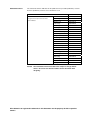
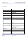
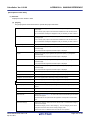
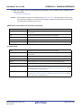
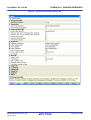
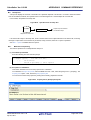
Related Documents
The related documents indicated in this publication may include preliminary versions.
However, preliminary versions are not marked as such.
Document Name
Document No.
CubeSuite+
Start
R20UT0545E
Integrated Development Environment
78K0 Design
R20UT0546E
User's Manual
78K0R Design
R20UT0547E
Caution
RL78 Design
R20UT0548E
V850 Design
R20UT0549E
R8C Design
R20UT0550E
78K0 Coding
R20UT0551E
RL78,78K0R Coding
R20UT0552E
V850 Coding
R20UT0553E
Coding for CX Compiler
R20UT0554E
R8C Coding
R20UT0576E
78K0 Build
R20UT0555E
RL78,78K0R Build
R20UT0556E
V850 Build
This manual
Build for CX Compiler
R20UT0558E
R8C Build
R20UT0575E
78K0 Debug
R20UT0559E
78K0R Debug
R20UT0560E
RL78 Debug
R20UT0561E
V850 Debug
R20UT0562E
R8C Debug
R20UT0574E
Analysis
R20UT0563E
Message
R20UT0407E
The related documents listed above are subject to change without
notice. Be sure to use the latest edition of each document when
designing.
All trademarks or registered trademarks in this document are the property of their respective
owners.
[MEMO]
[MEMO]
[MEMO]
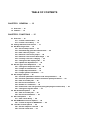
TABLE OF CONTENTS
CHAPTER 1 GENERAL ... 12
1.1 Overview ... 12
1.2 Features ... 14
CHAPTER 2 FUNCTIONS ... 15
2.1 Overview ... 15
2.1.1 Create a load module ... 15
2.1.2 Create a user library ... 16
2.2 Change the Build Tool Version ... 17
2.3 Set Build Target Files ... 18
2.3.1 Set a startup routine ... 18
2.3.2 Automatically generate link directives ... 20
2.3.3 Add a file to a project ... 25
2.3.4 Remove a file from a project ... 29
2.3.5 Remove a file from the build target ... 30
2.3.6 Classify a file into a category ... 30
2.3.7 Change the file display order ... 31
2.3.8 Update file dependencies ... 32
2.4 Set the Type of the Output File ... 35
2.4.1 Change the output file name ... 35
2.4.2 Output an assemble list ... 36
2.4.3 Output map information ... 37
2.4.4 Output symbol information ... 37
2.5 Set Compile Options ... 38
2.5.1 Perform optimization with the code size precedence ... 39
2.5.2 Perform optimization with the execution speed precedence ... 39
2.5.3 Add an include path ... 39
2.5.4 Set a macro definition ... 41
2.5.5 Enable C++ comments ... 42
2.5.6 Reduce the code size (perform prologue/epilogue runtime calls) ... 42
2.5.7 Change the register mode ... 43
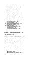
2.6 Set Assemble Options ... 44
2.6.1 Add an include path ... 44
2.6.2 Set a macro definition ... 46
2.7 Set Link Options ... 47
2.7.1 Add a user library ... 48
2.8 Set ROMization Process Options ... 50
2.8.1 Create an object for ROMization ... 50
2.9 Set Hex Convert Options ... 52
2.9.1 Set the output of a hex file ... 52
2.9.2 Fill the vacant area ... 53
2.10 Set Archive Options ... 55
2.10.1 Set the output of an archive file ... 55
2.11 Set Section File Generate Options ... 56
2.11.1 Automatically allocate variables through static analysis ... 56
2.12 Set Dump Options ... 58
2.12.1 Use the dump tool ... 58
2.12.2 Reference the section information ... 58
2.13 Set Cross Reference Options ... 59
2.13.1 Use the cross reference tool ... 59
2.14 Set Memory Layout Visualization Options ... 60
2.14.1 Use the memory layout visualization tool ... 60
2.15 Set Build Options Separately ... 61
2.15.1 Set build options at the project level ... 61
2.15.2 Set build options at the file level ... 61
2.16 Prepare for Implementing Boot-flash Relink Function ... 64
2.16.1 Prepare the build target files ... 64
2.16.2 Set the boot area project ... 64
2.16.3 Set the flash area project ... 66
2.17 Make Settings for Build Operations ... 68
2.17.1 Set the link order of files ... 68
2.17.2 Change the file build order of subprojects ... 69
2.17.3 Display a list of build options ... 69
2.17.4 Change the file build target project ... 69
2.17.5 Add a build mode ... 71
2.17.6 Change the build mode ... 73
2.17.7 Delete a build mode ... 74
2.17.8 Set the current build options as the standard for the project ... 75
2.18 Run a Build ... 76
2.18.1 Run a build of updated files ... 78
2.18.2 Run a build of all files ... 79
2.18.3 Run a build in parallel with other operations ... 79
2.18.4 Run builds in batch with build modes ... 81
2.18.5 Compile/assemble individual files ... 82
2.18.6 Stop running a build ... 83
2.18.7 Save the build results to a file ... 83
2.18.8 Delete intermediate files and generated files ... 83
2.19 Estimate the Stack Capacity ... 85
2.19.1 Starting and exiting ... 85
2.19.2 Check the call relationship ... 86
2.19.3 Check the stack information ... 87
2.19.4 Check unknown functions ... 88
2.19.5 Change the frame size ... 89
CHAPTER 3 BUILD OUTPUT LISTS ... 91
3.1 Assembler ... 91
3.1.1 Output method ... 91
3.1.2 Output example ... 91
3.2 Linker ... 94
3.3
3.4
3.5
3.6
3.7
3.8
3.9
3.2.1 Output method ... 94
3.2.2 Link map output example ... 94
Hex Converter ... 97
3.3.1 Intel expanded ... 97
3.3.2 Motorola S type ... 101
3.3.3 Expanded tektronix ... 103
Section File Generator ... 108
3.4.1 Cautions ... 111
Dump Tool ... 112
3.5.1 Dump list display contents ... 112
3.5.2 Element values and meanings ... 117
Disassembler ... 120
Cross Reference Tool ... 121
3.7.1 Cross reference ... 121
3.7.2 Tag information ... 122
3.7.3 Call tree ... 123
3.7.4 Function metrics ... 126
3.7.5 Call database ... 128
Memory Layout Visualization Tool ... 131
3.8.1 Memory map table ... 131
Format of Object File ... 133
3.9.1 Structure of object file ... 133
3.9.2 ELF header ... 133
3.9.3 Program header table ... 134
3.9.4 Section header table ... 134
3.9.5 Sections ... 136
APPENDIX A WINDOW REFERENCE ... 139
A.1 Description ... 139
APPENDIX B COMMAND REFERENCE ... 352
B.1 C Compiler ... 352
B.1.1 I/O files ... 354
B.1.2 Executable object ... 354
B.1.3 Method for manipulating ... 355
B.1.4 Option ... 357
B.1.5 Cautions ... 463
B.2 Assembler ... 470
B.2.1 I/O files ... 470
B.2.2 Method for manipulating ... 470
B.2.3 Option ... 471
B.2.4 Cautions ... 499
B.3 Linker ... 506
B.3.1 Method for manipulating ... 509
B.3.2 Option ... 510
B.3.3 Boot-flash relink function ... 556
B.3.4 Supplementary information ... 570
B.4 ROMization Processor ... 578
B.4.1 I/O files ... 580
B.4.2 rompsec section ... 580
B.4.3 Creating object for ROMization ... 583
B.4.4 Copy function ... 590
B.4.5 Example of using copy function ... 595
B.4.6 Method for manipulating ... 597
B.4.7 Option ... 597
B.5 Hex Converter ... 614
B.5.1 I/O files ... 614
B.5.2 Method for manipulating ... 614
B.5.3 Option ... 615
B.6 Archiver ... 632
B.6.1 Method for manipulating ... 632
B.6.2 Key/Option ... 633
B.7 Section File Generator ... 651
B.7.1 Section file ... 651
B.7.2 Method for manipulating ... 653
B.7.3 Option ... 655
B.7.4 Cautions ... 677
B.8 Dump Tool ... 678
B.8.1 Method for manipulating ... 678
B.8.2 Option ... 679
B.9 Disassembler ... 707
B.9.1 Method for manipulating ... 707
B.9.2 Option ... 708
B.9.3 Cautions ... 724
B.10 Cross Reference Tool ... 725
B.10.1 Input/Output ... 725
B.10.2 Method for manipulating ... 726
B.10.3 Option ... 727
B.11 Memory Layout Visualization Tool ... 764
B.11.1 Input/Output ... 764
B.11.2 Method for manipulating ... 764
B.11.3 Option ... 765
APPENDIX C INDEX ... 777
CubeSuite+ Ver.1.00.00
CHAPTER 1 GENERAL
CHAPTER 1 GENERAL
This chapter explains the product overview of the build tool.
1.1
Overview
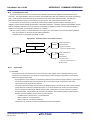
The build tool is comprised of components provided by this product. It enables various types of information to be configured via a GUI tool, enabling you to generate ROMization object file, load module file, hex file, or archive file from your
source files, according to your objectives.
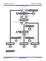
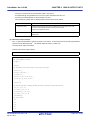
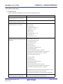
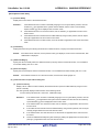
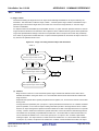
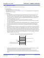
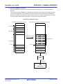
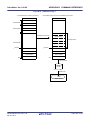
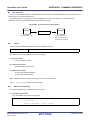
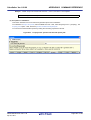
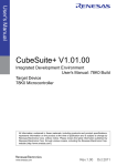
The build tool process flow is shown below.
R20UT0557EJ0100 Rev.1.00
Apr 01, 2011
Page 12 of 782
CubeSuite+ Ver.1.00.00
CHAPTER 1 GENERAL
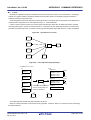
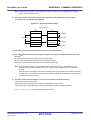
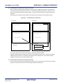
Figure 1-1. Build Tool Process Flow
C source files
...
Section file generator
C compiler
Include file
Section file
Assembler source files
...
Assembler
Relocatable object files
...
Archiver
Archive file
Linker
Link directive file
Load module file
Memory layout visualization tool
ROMization processor
Memory map table
Cross reference tool
Output information file
ROMization object file
Hex converter
Dump tool
Hex file
Dump list
DisassemblerNote
Note Command line only
R20UT0557EJ0100 Rev.1.00
Apr 01, 2011
Page 13 of 782
CubeSuite+ Ver.1.00.00
1.2
CHAPTER 1 GENERAL
Features
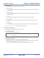
The features of the build tools are shown below.
- Optimization function
You can generate efficient object module files by performing optimizations such as prioritizing code size or execution speed when compiling.
It is possible to select from six optimization levels and set a different optimization level for each source.
- Functions optimized for embedded systems
It is possible to write interrupt processing and real-time OS tasks in C language.
Access to the peripheral hardware of the microcomputer can be handled in the same way as normal access to
variables.
Overhead associated with saving to and restoring from registers during interrupt processing is reduced by restricting the number of general registers that are used by the C compiler (register mode).
It is possible to fill the holes between members of structures and unions formed by alignment and handle the structures and unions predetermined by alignment (structure/union packing function).
R20UT0557EJ0100 Rev.1.00
Apr 01, 2011
Page 14 of 782
CubeSuite+ Ver.1.00.00
CHAPTER 2 FUNCTIONS
CHAPTER 2 FUNCTIONS
This chapter describes the build procedure using CubeSuite+ and about the main build functions.
2.1
Overview
This section describes how to create a load module and user library.
2.1.1
Create a load module
The procedure for creating a load module is shown below.
(1) Create or load a project
Create a new project, or load an existing one.
Remark
See "CubeSuite+ Start" for details about creating a new project or loading an existing one.
(2) Set a build target project
Set a build target project (see "2.17 Make Settings for Build Operations").
If there is no subproject, the project is always active.
Remarks 1.
2.
If there is no subproject in the project, the project is always active.
When setting a build mode, add the build mode (see "2.17.5 Add a build mode").
(3) Set build target files
Add or remove build target files and update the dependencies (see "2.3 Set Build Target Files").
Remarks 1.
2.
See "2.7.1 Add a user library" for the method of adding a user library to the project.
Also, you can set the link order of object module files and library files (see "2.17.1 Set the link
order of files").
(4) Specify the output of a load module
Select the type of the load module to be generated (see "2.4 Set the Type of the Output File").
(5) Set build options
Set the options for the compiler, assembler, linker, and the like (see "2.5 Set Compile Options", "2.6 Set
Assemble Options", "2.7 Set Link Options").
(6) Run a build
Run a build (see "2.18 Run a Build").
The following types of builds are available.
- Build (see "2.18.1 Run a build of updated files")
- Rebuild (see "2.18.2 Run a build of all files")
- Rapid build (see "2.18.3 Run a build in parallel with other operations")
- Batch build (see "2.18.4 Run builds in batch with build modes")
Remark
If there are any commands you wish to run before or after the build process, on the Property panel,
from the [Common Options] tab, in the [Others] category, set the [Commands executed before build
processing] and [Commands executed after build processing] properties.
If there are any commands you wish to run before or after the build process at the file level, you can set
R20UT0557EJ0100 Rev.1.00
Apr 01, 2011
Page 15 of 782
CubeSuite+ Ver.1.00.00
CHAPTER 2 FUNCTIONS
them from the [Individual Compile Options] tab (for a C source file) and [Individual Assemble Options]
tab (for an assembler source file).
(7) Save the project
Save the setting contents of the project to the project file.
Remark
2.1.2
See "CubeSuite+ Start" for details about saving the project.
Create a user library
The procedure for creating a user library is shown below.
(1) Create or load a project
Create a new project, or load an existing one.
When you create a new project, set a library project.
Remark
See "CubeSuite+ Start" for details about creating a new project or loading an existing one.
(2) Set a build target project
Set a build target project (see "2.17 Make Settings for Build Operations").
If there is no subproject, the project is always active.
Remarks 1.
2.
If there is no subproject in the project, the project is always active.
When setting a build mode, add the build mode (see "2.17.5 Add a build mode").
(3) Set build target files
Add or remove build target files and update the dependencies (see "2.3 Set Build Target Files").
(4) Set build options
Set the options for the compiler, assembler, archiver, and the like (see "2.5 Set Compile Options", "2.6 Set
Assemble Options", "2.10 Set Archive Options").
Remark
To create a library common to various devices, set the [Output common object file for various devices]
property in the [Output File Type and Path] category from the [Common Options] tab on the Property
panel.
(5) Run a build
Run a build (see "2.18 Run a Build").
The following types of builds are available.
- Build (see "2.18.1 Run a build of updated files")
- Rebuild (see "2.18.2 Run a build of all files")
- Rapid build (see "2.18.3 Run a build in parallel with other operations")
- Batch build (see "2.18.4 Run builds in batch with build modes")
Remark
If there are any commands you wish to run before or after the build process, on the Property panel,
from the [Common Options] tab, in the [Others] category, set the [Commands executed before build
processing] and [Commands executed after build processing] properties.
If there are any commands you wish to run before or after the build process at the file level, you can set
them from the [Individual Compile Options] tab (for a C source file) and [Individual Assemble Options]
tab (for an assembler source file).
R20UT0557EJ0100 Rev.1.00
Apr 01, 2011
Page 16 of 782
CubeSuite+ Ver.1.00.00
CHAPTER 2 FUNCTIONS
(6) Save the project
Save the setting contents of the project to the project file.
Remark
2.2
See "CubeSuite+ Start" for details about saving the project.
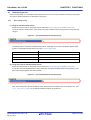
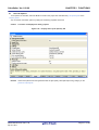
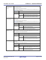
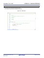
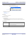
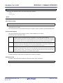
Change the Build Tool Version
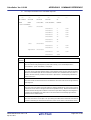
You can change the version of the build tool (compiler package) used in the project (main project or subproject).
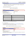
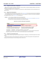
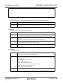
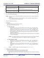
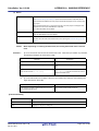
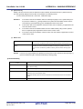
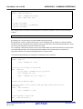
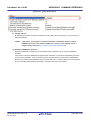
Select the build tool node on the project tree and select the [Common Options] tab on the Property panel. Select
[Always latest version which was installed] or the version on the [Using compiler package version] property in the [Version
Select] category.
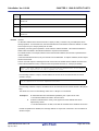
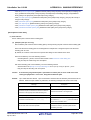
Figure 2-1. [Version Select] Category
Remarks 1.
When the build tool used in the main project and subprojects is the same, you can collectively change
the build tool version by selecting all of the Build tool nodes and setting the property.
2.
If you have selected a compiler package that has not been installed (e.g. if you open a project created
in another execution environment), then that version is also displayed.
3.
If the options change depending on the compiler package, then the display of the build tool's properties
will change according to the selected version.
Properties that are hidden when the version is changed are saved in the project file's settings, and the
values will be reproduced when the properties are displayed again.
Options are changed in accordance with the following rules. Information about changes is displayed in
the Output panel.
- If you change from an older version to a newer version, the option settings will be inherited and
converted (only if necessary).
- If you change from a newer version to an older version, only identical option settings will be
inherited.
Options that only exist in the older version will be set to the default values.
R20UT0557EJ0100 Rev.1.00
Apr 01, 2011
Page 17 of 782
CubeSuite+ Ver.1.00.00
2.3
CHAPTER 2 FUNCTIONS
Set Build Target Files
Before running a build, you must add the build target files (such as C source file, assembler source file) to the project.
This section explains operations on setting files in the project.
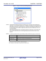
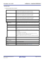
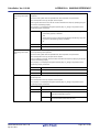
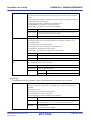
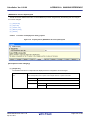
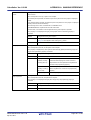
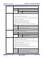
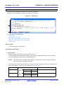
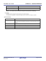
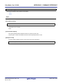
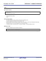
2.3.1
Set a startup routine
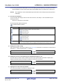
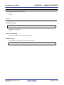
(1) Using the standard startup routine
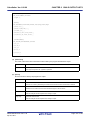
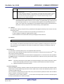
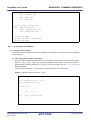
Select the build tool node on the project tree and select the [Compile Options] tab on the Property panel.
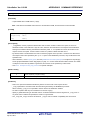
To use the standard startup routine, select [Yes] on the [Use standard startup routine] property in the [Input File]
category.
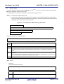
Figure 2-2. [Use standard startup routine] Property
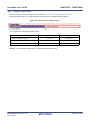
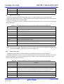
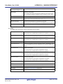
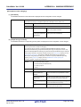
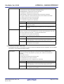
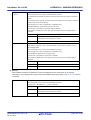
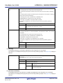
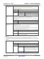
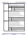
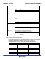
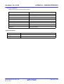
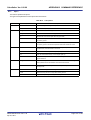
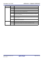
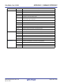
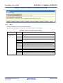
The following file is used as the standard startup routine, depending on the value of the [Select register mode]
property in the [Register Mode] category from the [Common Options] tab.
Value of [Select register mode] Property
Standard Startup Routine
32-register mode(None)
Using compiler package install folder\lib850\r32\crtE.o
26-register mode(-reg26)
Using compiler package install folder\lib850\r26\crtE.o
22-register mode(-reg22)
Using compiler package install folder\lib850\r22\crtE.o
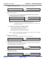
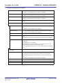
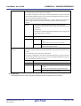
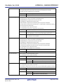
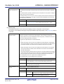
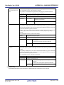
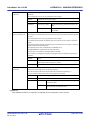
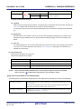
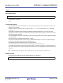
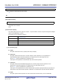
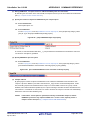
(2) Using other than the standard startup routine
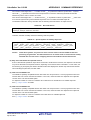
Select the build tool node on the project tree and select the [Compile Options] tab on the Property panel.
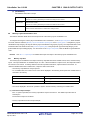
To use other than the standard startup routine, select [No] on the [Use standard startup routine] property in the
[Input File] category ([Yes] is selected by default).
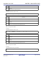
Figure 2-3. [Use standard startup routine] Property
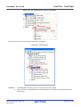
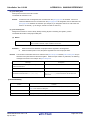
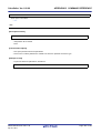
Next, add a startup file (a file that the startup routine is described) to the Startup node on the project tree. See
"2.3.3 Add a file to a project" for the method of adding the file to the project tree.
R20UT0557EJ0100 Rev.1.00
Apr 01, 2011
Page 18 of 782
CubeSuite+ Ver.1.00.00
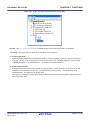
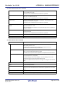
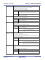
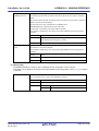
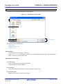
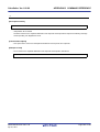
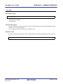
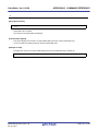
CHAPTER 2 FUNCTIONS
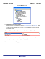
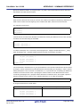
Figure 2-4. Project Tree Panel (After Adding Startup File)
Caution
A build target file added directly below the Startup node on the project tree is treated as the
startup file. It is not treated as a startup file if it is added to the category below the Startup node.
When adding a startup file to the Startup node, if a startup file has already been added then only
the latest startup file to be added is targeted by a build; any such files added prior to this one
will not be targeted.
When setting a startup file that is not targeted by a build as a build target, if other startup files
have also been added then the file will be targeted by the build, and the others will not be
targeted.
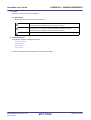
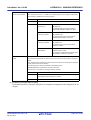
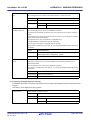
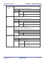
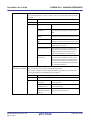
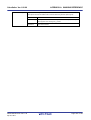
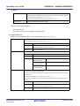
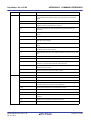
Remark
To create a new startup routine, copy the following sample and add it to the project. And then edit it.
Register Mode
Sample of Startup Routine
32-register mode
Using compiler package install folder\lib850\r32\crtE.s
26-register mode
Using compiler package install folder\lib850\r26\crtE.s
22-register mode
Using compiler package install folder\lib850\r22\crtE.s
A startup routine must be described in assembly language.
See “CubeSuite+ V850 Coding” for details about a startup routine.
R20UT0557EJ0100 Rev.1.00
Apr 01, 2011
Page 19 of 782
CubeSuite+ Ver.1.00.00
2.3.2
CHAPTER 2 FUNCTIONS
Automatically generate link directives
Although users can create a link directive file and add it to a project, it is also possible to generate it automatically in
CubeSuite+.
Remark
See “CubeSuite+ V850 Coding” for details about link directives and creating a link directive file.
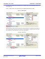
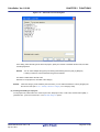
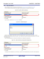
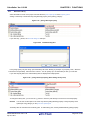
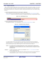
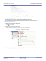
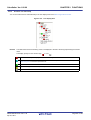
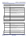
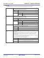
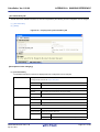
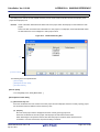
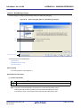
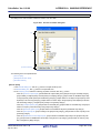
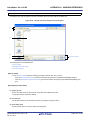
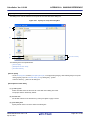
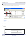
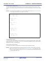
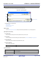
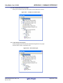
On the project tree, select the Build tool node, and then select [Create Link Directive File...] from the context menu.
The Link Directive File Generation dialog box opens.
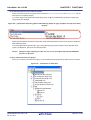
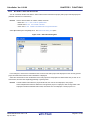
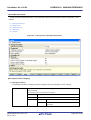
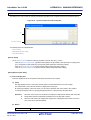
Figure 2-5. Link Directive File Generation Dialog Box
Edit the segments/sections and symbols in the dialog box.
R20UT0557EJ0100 Rev.1.00
Apr 01, 2011
Page 20 of 782
CubeSuite+ Ver.1.00.00
CHAPTER 2 FUNCTIONS
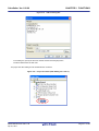
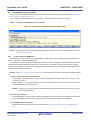
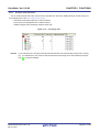
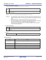
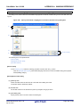
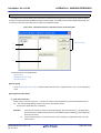
(1) Edit segments/sections
The [Segment / Section list] area displays the device memory allocation information, and a list of the currently
configured segments and sections.
When a segment/section is selected from the list, detailed information on that segment/section is displayed in the
[Segment/Section detail] area. Edit the items in the [Segment / Section detail] area.
Remark
Some items in reserved sections cannot be edited (items for which values are set automatically).
See “APPENDIX A WINDOW REFERENCE”, “Link Directive File Generation dialog box” for details
about each item and how reserved sections are handled.
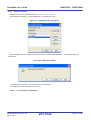
Figure 2-6. Segment Detail (When SCONST Is Selected)
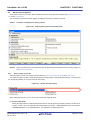
Figure 2-7. Section Detail (When .sconst Is Selected)
Segments and sections can also be added.
Click [Add Segment] to add a new segment "NewSegment_XXX" directly below the row selected in the list (XXX: 0
to 255 in decimal numbers). Edit the items in the [Segment / Section detail] area. By default, [Attribute] is set to
R20UT0557EJ0100 Rev.1.00
Apr 01, 2011
Page 21 of 782
CubeSuite+ Ver.1.00.00
CHAPTER 2 FUNCTIONS
[Executable(RX)] (if added to the internal ROM area or non mapping area) or to [Read/Write(RW)] (if added to the
internal RAM area).
Caution
When a section row is selected in the list, the [Add segment] button is invalid.
Figure 2-8. Add Segment
Click [Add Section] to add a new section "NewSection_XXX" directly below the row selected in the list (XXX: 0 to
255 in decimal numbers). Edit the items in the [Segment / Section detail] area. By default, [Type] is set to [Exist
data (PROGBITS)], and [Attribute] inherits the value of the parent segment.
Figure 2-9. Add Section
R20UT0557EJ0100 Rev.1.00
Apr 01, 2011
Page 22 of 782
CubeSuite+ Ver.1.00.00
CHAPTER 2 FUNCTIONS
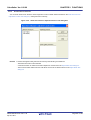
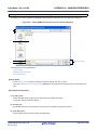
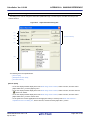
(2) Edit symbols
The [Symbol list] area displays the list of currently configured symbols.
When a symbol is selected from the list, detailed information on that symbol is displayed in the [Symbol detail]
area. Edit the items in the [Symbol detail] area.
Figure 2-10. Segment Detail (When _tp_TEXT Is Selected)
Symbols can also be added.
Click [Add symbol] to add a new symbol "NewSymbol_XXX" directly below the row selected in the list (XXX: 0 to
255 in decimal numbers). Edit the items in the [Symbol detail] area. By default, [Type] is set to [TP
symbol(%TP_SYMBOL)].
Figure 2-11. Add Symbol
After editing the segments/sections and symbols, click the [Generate] button.
A link directive file (named project-name.dir) is generated based on the specified memory, segments, sections, and
symbol allocation information, and then added to the project.
The link directive file is generated in the project folder. The link directive file that has been generated is also shown on
the project tree, under the File node.
R20UT0557EJ0100 Rev.1.00
Apr 01, 2011
Page 23 of 782
CubeSuite+ Ver.1.00.00
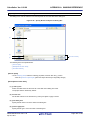
CHAPTER 2 FUNCTIONS
Figure 2-12. Project Tree Panel (After Generating Link Directive File)
Caution
The generated link directive file will be a build target. If a link directive file has already been
registered to the project, then the file will be removed from the build target.
R20UT0557EJ0100 Rev.1.00
Apr 01, 2011
Page 24 of 782
CubeSuite+ Ver.1.00.00
2.3.3
CHAPTER 2 FUNCTIONS
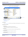
Add a file to a project
Files can be added to a project by the following methods.
- Adding an existing file
- Creating and adding an empty file
(1) Adding an existing file
(a) Add individual files
Drag a folder from Explorer or the like, and drop it onto the empty space below the project tree.
The file is added below the File node.
Figure 2-13. Project Tree Panel (File Drop Location)
Drop the file here
Caution
To add other than a startup routine, drop a file onto the Startup node. See "2.3.1 Set a
startup routine" for details about using other than a startup routine.
(b) Add a folder
Drag a folder from Explorer or the like, and drop it onto the empty space below the project tree. The Add
Folder and File dialog box opens.
Remark
You can also add multiple folders to the project at the same time by dragging multiple folders at
same time and dropping them onto the project tree.
Caution
When a folder with the name that is more than 200 characters is dropped, the folder is
added to the project tree as a category with the name that 201st character and after are
deleted.
R20UT0557EJ0100 Rev.1.00
Apr 01, 2011
Page 25 of 782
CubeSuite+ Ver.1.00.00
CHAPTER 2 FUNCTIONS
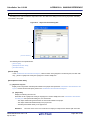
Figure 2-14. Add Folder and File Dialog Box
In the dialog, select the file types to add to the project, specify the number of subfolder levels to add, and then
click the [OK] button.
Remark
You can select multiple file types by left clicking while holding down the [Ctrl] or [Shift] key.
If nothing is selected, it is assumed that all types are selected.
The folder is added below the File node.
Note that on the project tree, the folder is the category.
Remark
When the category node created by the user exists, you can add a file below the node by dropping the
file onto the node (see "2.3.6 Classify a file into a category" for a category node).
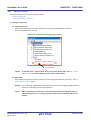
(2) Creating and adding an empty file
On the project tree, select either one of the Project node, Subproject node, or File node, and then select [Add] >>
[Add New File...] from the context menu. The Add File dialog box opens.
R20UT0557EJ0100 Rev.1.00
Apr 01, 2011
Page 26 of 782
CubeSuite+ Ver.1.00.00
CHAPTER 2 FUNCTIONS
Figure 2-15. Add File Dialog Box
In the dialog box, specify the file to be created and then click the [OK] button.
The file is added below the File node.
The project tree after adding the file will look like the one below.
Figure 2-16. Project Tree Panel (After Adding File "main.c")
R20UT0557EJ0100 Rev.1.00
Apr 01, 2011
Page 27 of 782
CubeSuite+ Ver.1.00.00
CHAPTER 2 FUNCTIONS
Figure 2-17. Project Tree Panel (After Adding Folder "src")
Remark
The location of the file added below the File node depends on the current file display order setting. See
"2.3.7 Change the file display order" for the method of changing the file display order.
Cautions 1.
If the paths differ, you can add source files with the same name. Note, however, that if the
setting of the output file name is left as the default, the output files will have the same name,
which will prevent the build from running correctly (for example, when adding
D:\sample1\func.c and D:\sample2\func.c, the default output file name for these files is both
func.o).
To avoid this problems, set the output file name for each of those files to a different name with
the individual build options for the source files.
Changing the name of the C source file is made with the [Object file name] property in the
[Output File] category from the [Individual Compile Options] tab. Changing the name of the
assembler source file is made with the [Object file name] property in the [Output File] category
from the [Individual Assemble Options] tab. See "2.15.2 Set build options at the file level" for
how to set the individual build options.
2.
3.
If source files with the same name are added, the target file cannot opened during debugging.
If a file with an extension of "dr" or "dir" is added to the project, it is treated as a link directive
file. It is also treated as a link directive file if it is added below the Startup node.
When adding a link directive file to the project, if a link directive file has already been added
then only the latest link directive file to be added is targeted by a build; any such files added
prior to this one will not be targeted.
When setting a link directive file that is not targeted by a build as a build target, if other link
directive files have also been added then the file will be targeted by the build, and the others will
not be targeted.
4.
Up to 5000 files can be added to the main project or subproject.
When a new file is added, an empty file is created in the location specified in the Add File dialog box.
By double clicking the file name on the project tree, you can open the Editor panel and edit the file.
The files that can be opened with the Editor panel are shown below.
- C source file (.c)
R20UT0557EJ0100 Rev.1.00
Apr 01, 2011
Page 28 of 782
CubeSuite+ Ver.1.00.00
CHAPTER 2 FUNCTIONS
- Assembler source file (.s)
- Header file (.h, .inc)
- Link directive file (.dr, .dir)
- Section file (.sf)
- Map file (.map)
- Hex file (.hex)
- Text file (.txt)
Remarks 1.
You can use one of the methods below to open files other than those listed above in the Editor panel.
- Drag a file and drop it onto the Editor panel.
- Select a file and then select [Open with Internal Editor...] from the context menu.
2.
When the environment is set to use an external editor on the Option dialog box, the file is opened with
the external editor that has been set. Other files are opened with the applications associated by the
host OS.
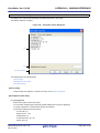
2.3.4
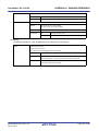
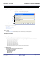
Remove a file from a project
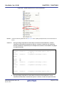
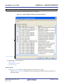
To remove a file added to a project, select the file to be removed from the project on the project tree and then select
[Remove from Project] from the context menu.
In addition, the file itself is not deleted from the file system.
Figure 2-18. [Remove from Project] Item
R20UT0557EJ0100 Rev.1.00
Apr 01, 2011
Page 29 of 782
CubeSuite+ Ver.1.00.00
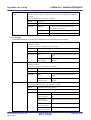
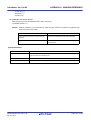
2.3.5
CHAPTER 2 FUNCTIONS
Remove a file from the build target
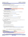
You can remove a specific file from the build target out of all the files added to the project.
Select the file to be removed from the build target on the project tree and select the [Build Settings] tab on the Property
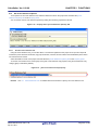
panel. Select [No] on the [Set as build-target] property in the [Build] category.
Figure 2-19. [Set as build-target] Property
Remark
The files that can be applied this function are C source files, assembler source files, link directive files,
section file, object files, and archive file.
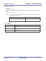
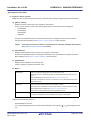
2.3.6
Classify a file into a category
You can create a category under the File node and classify files by the category. This makes it easier to view files
added to the project on the project tree, and makes it easier to manage files according to function.
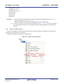
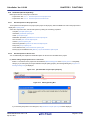
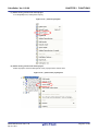
To create a category node, select either one of the Project node, Subproject node, or File node on the project tree, and
then select [Add] >> [Add New Category] from the context menu.
Figure 2-20. [Add New Category] Item (For File Node)
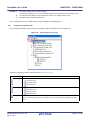
Figure 2-21. Project Tree Panel (After Adding Category Node)
R20UT0557EJ0100 Rev.1.00
Apr 01, 2011
Page 30 of 782
CubeSuite+ Ver.1.00.00
Remarks 1.
CHAPTER 2 FUNCTIONS
The default category name is "New category".
To change the category name, you can use [Rename] from the context menu of the category node.
2.
You can also add a category node with the same name as an existing category node.
3.
Categories can be nested up to 20 levels.
You can classify files into the created category node by dragging and dropping the file.
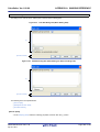
2.3.7
Change the file display order
You can change the display order of the files and category nodes using the buttons on the project tree.
Figure 2-22. Toolbar (Project Tree Panel)
Select any of the buttons below on the toolbar of the Project Tree panel.
Button
Description
Sorts category nodes and files by name.
: Ascending order
: Descending order
: Ascending order
Sorts category nodes and files by timestamp.
: Descending order
: Ascending order
: Descending order
Displays category nodes and files in the specified order by the user (default).
You can change the display order of the category nodes and files arbitrarily by dragging and dropping
them.
R20UT0557EJ0100 Rev.1.00
Apr 01, 2011
Page 31 of 782
CubeSuite+ Ver.1.00.00
2.3.8
CHAPTER 2 FUNCTIONS
Update file dependencies
When you perform a change (changing include file paths, adding an include statement of the header file to the C source
file and assembler source file, etc.) that effects the file dependencies in the compile option settings or assemble option
settings, you must update the dependencies of the relevant files.
Updating file dependencies is performed for the entire project (main project and subprojects) or active project.
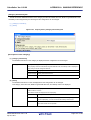
(1) For the entire project
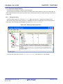
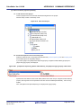
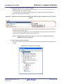
From the [Build] menu, select [Update Dependencies].
Figure 2-23. [Update Dependencies] Item
(2) For the active project
From the [Build] menu, select [Update Dependencies of active project].
R20UT0557EJ0100 Rev.1.00
Apr 01, 2011
Page 32 of 782
CubeSuite+ Ver.1.00.00
CHAPTER 2 FUNCTIONS
Figure 2-24. [Update Dependencies of active project] Item
Remark
If there are files being edited with the Editor panel when updating file dependencies, then all these files are
saved.
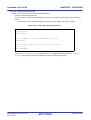
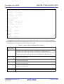
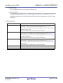
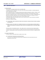
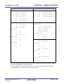
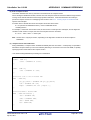
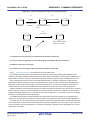
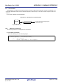
Cautions 1.
During checking of dependence relationships of include files with CubeSuite+, condition
statements such as #if and comments are ignored. Therefore, include files not required for
build are mistaken as required files (In the example below, header1.h and header5.h are judged
as required for build).
#if
0
#include
"header1.h"
#else
#include
/* Dependence relationship judged to exist */
/* ! zero */
"header2.h"
/* Dependence relationship to exist */
#endif
#define
AAA
#ifdef
AAA
#include
"header3.h"
/* Dependence relationship to exist */
"header4.h"
/* Dependence relationship to exist */
"header5.h"
/* Dependence relationship judged to exist */
#else
#include
#endif
/*
#include
*/
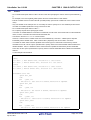
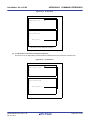
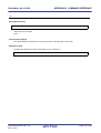
2.
During checking of dependence relationships of include files with CubeSuite+, include
statements described after comments are ignored. Therefore, include files required for build
R20UT0557EJ0100 Rev.1.00
Apr 01, 2011
Page 33 of 782
CubeSuite+ Ver.1.00.00
CHAPTER 2 FUNCTIONS
are mistaken as no-required files (In the example below, header6.h and header7.h are judged as
no-required for build).
/* Dependence relationship judged not to exist */
/* comment */
#include
"header6.h"
/* Dependence relationship judged not to exist */
/*
comment
*/
#include
R20UT0557EJ0100 Rev.1.00
Apr 01, 2011
"header7.h"
Page 34 of 782
CubeSuite+ Ver.1.00.00
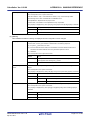
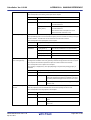
2.4
CHAPTER 2 FUNCTIONS
Set the Type of the Output File
Set the type of the file to be output as the product of the build.
Select the build tool node on the project tree and select the [Common Options] tab on the Property panel. Select the
file type on the [Output file type] property in the [Output File Type and Path] category.
Figure 2-25. [Output file type] Property
(1) When [Execute Module(ROMization Module)] is selected
A ROMization module file is created.
The file set in the [Output File] category on the [ROMization Process Options] tab is the debug target.
(2) When [Execute Module(Load Module File)] is selected (default)
A load module file is created.
The file set in the [Output File] category on the [Link Options] tab is the debug target.
(3) When [Execute Module(Hex File)] is selected
A hex file is also created.
The file set in the [Output File] category on the [Hex Convert Options] tab is the debug target.
Caution
2.4.1
For library projects, this property is always [Library] and cannot be changed.
Change the output file name
The names of the ROMization module file, load module file, hex file, archive file output by the build tool are set to the
following names by default.
"%ProjectName%" is an embedded macro. It is replaced to the project name.
ROMization module file name: romp.out
Load module file name: %ProjectName%.out
Hex file name: %ProjectName%.hex
Archive file name: lib%ProjectName%.a
The method to change these file names is shown below.
(1) When changing the ROMization module file name
Select the build tool node on the project tree and select the [ROMization Process Options] tab on the Property
panel. Enter the file name to be changed to on the [ROMized object file name] property in the [Output File]
category.
Figure 2-26. [ROMized object file name] Property (For ROMized Module File)
Remark
You can also change the option in the same way with the [ROMized object file name] property in the
[Frequently Used Options(for ROMization)] category on the [Common Options] tab.
R20UT0557EJ0100 Rev.1.00
Apr 01, 2011
Page 35 of 782
CubeSuite+ Ver.1.00.00
CHAPTER 2 FUNCTIONS
(2) When changing the load module file name
Select the build tool node on the project tree and select the [Link Options] tab on the Property panel. Enter the file
name to be changed to on the [Output file name] property in the [Output File] category.
Figure 2-27. [Output file name] Property (For Load Module File)
Remark
You can also change the option in the same way with the [Output file name] property in the [Frequently
Used Options(for Link)] category on the [Common Options] tab.
(3) When changing the hex file name
Select the build tool node on the project tree and select the [Hex Convert Options] tab on the Property panel. Enter
the file name to be changed to on the [Hex file name] property in the [Output File] category.
Figure 2-28. [Hex file name] Property
Remark
You can also change the option in the same way with the [Hex file name] property in the [Frequently
Used Options(for Hex Convert)] category on the [Common Options] tab.
(4) When changing the archive file name
Select the build tool node on the project tree and select the [Archive Options] tab on the Property panel. Enter the
file name to be changed to on the [Output file name] property in the [Output File] category.
Figure 2-29. [Output file name] Property (For Archive File)
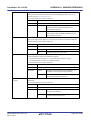
2.4.2
Output an assemble list
The results of the assembly are output to the assembler list file.
Select the build tool node on the project tree and select the [Assemble Options] tab on the Property panel. To output
the assemble list, select [Yes(-a -l)] on the [Output assemble list file] property in the [Assemble List] category.
Figure 2-30. [Output assemble list file] Property
Remark
See "3.1 Assembler" for the assemble list.
R20UT0557EJ0100 Rev.1.00
Apr 01, 2011
Page 36 of 782
CubeSuite+ Ver.1.00.00
2.4.3
CHAPTER 2 FUNCTIONS
Output map information
Map information (information on the location of section) is output to the link map file.
Select the build tool node on the project tree and select the [Link Options] tab on the Property panel. To output the link
map file, select [Yes(-m)] on the [Output link map file] property in the [Link Map] category.
Figure 2-31. [Output link map file] Property (For Map Information)
When outputting a link map file, you can set the output folder and output file name.
(1) Set the output folder
Setting the output folder is made with the [Output folder for link map file] property by directly entering to the text box
or by the [...] button. Up to 247 characters can be specified in the text box. "%BuildModeName%" is set by default.
"%BuildModeName%" is an embedded macro. It is replaced to the build mode name.
(2) Set the output file name
Setting the output file is made with the [Link map file name] property by directly entering to the text box. Up to 259
characters can be specified in the text box. "%ProjectName%.map" is set by default. "%ProjectName%" is an
embedded macro. It is replaced to the project name.
Remark
2.4.4
See "3.2 Linker" for map information.
Output symbol information
To output symbol information defined in the input module, use the -t option of the dump tool.
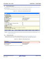
Select the build tool node on the project tree and select the [Dump Options] tab on the Property panel.
Set the -t option in the [Dump Tool] category. If you select [Yes] on the [Use dump tool] property, the [Additional options
for dump tool] property is displayed.
Figure 2-32. [Use dump tool] and [Additional options for dump tool] Property
Specify "-t" on the [Additional options for dump tool] property.
Remarks 1.
2.
See "(8) Symbol table" for symbol information to be output.
If "-t num" on the [Additional options for dump tool] property, the numth and greater symbol table entries
will be displayed. If "-v" is also specified, a value such as a section attribute can be displayed as a
string instead of a number.
See "B.8.2 Option" for details about the options.
R20UT0557EJ0100 Rev.1.00
Apr 01, 2011
Page 37 of 782
CubeSuite+ Ver.1.00.00
2.5
CHAPTER 2 FUNCTIONS
Set Compile Options
To set options for the compiler, select the Build tool node on the project tree and select the [Compile Options] tab on the
Property panel.
You can set the various compile options by setting the necessary properties in this tab.
Figure 2-33. Property Panel: [Compile Options] Tab
Remark
Often used options have been gathered under the [Frequently Used Options(for Compile)] category on the
[Common Options] tab.
R20UT0557EJ0100 Rev.1.00
Apr 01, 2011
Page 38 of 782
CubeSuite+ Ver.1.00.00
2.5.1
CHAPTER 2 FUNCTIONS
Perform optimization with the code size precedence
Select the build tool node on the project tree and select the [Compile Options] tab on the Property panel.
To perform optimization with the code size precedence, select [Level 2 Advanced Opt.(Code size precedence)(-Os)] on
the [Type of the optimization] property in the [Optimization] category ([Default Optimization(None)] is selected by default).
Figure 2-34. [Type of the optimization] Property (Code Size Precedence)
Remarks 1.
You can also set the option in the same way with the [Type of the optimization] property in the
[Frequently Used Options(for Compile)] category on the [Common Options] tab.
2.
2.5.2
See "(3) Efficient use of optimization" for details about optimization.
Perform optimization with the execution speed precedence
Select the build tool node on the project tree and select the [Compile Options] tab on the Property panel.
To perform optimization with the execution speed precedence, select [Level 2 Advanced Opt.(Speed precedence)(-Ot)]
on the [Type of the optimization] property in the [Optimization] category ([Default Optimization(None)] is selected by
default).
Figure 2-35. [Type of the optimization] Property (Execution Speed Precedence)
Remarks 1.
You can also set the option in the same way with the [Type of the optimization] property in the
[Frequently Used Options(for Compile)] category on the [Common Options] tab.
2.
2.5.3
See "(3) Efficient use of optimization" for details about optimization.
Add an include path
Select the build tool node on the project tree and select the [Compile Options] tab on the Property panel.
The include path setting is made with the [Additional include paths] property in the [Preprocess] category.
Figure 2-36. [Additional include paths] Property
If you click the [...] button, the Path Edit dialog box will open.
R20UT0557EJ0100 Rev.1.00
Apr 01, 2011
Page 39 of 782
CubeSuite+ Ver.1.00.00
CHAPTER 2 FUNCTIONS
Figure 2-37. Path Edit Dialog Box
Enter an include path per line in [Path(One path per one line)]. You can specify up to 259 characters per line, up to 64
line.
Remark
You can also specify the include path by dragging and dropping from Explorer or the like, or by the
[Browse...] button. Select the [Subfolders are automatically included] check box before clicking the
[Browse...] button to add all paths under the specified one (down to 5 levels) to [Path(One path per one
line)].
If you click the [OK] button, the entered include paths are displayed as subproperties.
Figure 2-38. [Additional include paths] Property (After Adding Include Paths)
To change the include paths, you can use the [...] button or enter the path directly in the text box of the subproperty.
When the include path is added to the project tree, the path is added to the top of the subproperties automatically.
Remark
You can also set the option in the same way with the [Additional include paths] property in the [Frequently
Used Options(for Compile)] category on the [Common Options] tab.
R20UT0557EJ0100 Rev.1.00
Apr 01, 2011
Page 40 of 782
CubeSuite+ Ver.1.00.00
2.5.4
CHAPTER 2 FUNCTIONS
Set a macro definition
Select the build tool node on the project tree and select the [Compile Options] tab on the Property panel.
The macro definition setting is made with the [Macro definition] property in the [Preprocess] category.
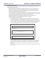
Figure 2-39. [Macro definition] Property
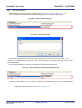
If you click the [...] button, the Text Edit dialog box will open.
Figure 2-40. Text Edit Dialog Box
Enter the macro definition in the format of "macro name=defined value", with one macro name per line. You can
specify up to 256 characters per line, up to 30 line. The "=defined value" part can be omitted, and in this case, "1" is used
as the defined value.
If you click the [OK] button, the entered macro definitions are displayed as subproperties.
Figure 2-41. [Macro definition] Property (After Setting Macros)
To change the macro definitions, you can use the [...] button or enter the path directly in the text box of the subproperty.
R20UT0557EJ0100 Rev.1.00
Apr 01, 2011
Page 41 of 782
CubeSuite+ Ver.1.00.00
Remark
CHAPTER 2 FUNCTIONS
You can also set the option in the same way with the [Macro definition] property in the [Frequently Used
Options(for Compile)] category on the [Common Options] tab.
2.5.5
Enable C++ comments
Select the build tool node on the project tree and select the [Compile Options] tab on the Property panel.
To enable C++ comments, select [Yes(-Xcxxcom)] on the [Use C++ style comment] property in the [Preprocess]
category (default).
Figure 2-42. [Use C++ style comment] Property
2.5.6
Reduce the code size (perform prologue/epilogue runtime calls)
It is possible to reduce the code size by performing a part of prologue/epilogue processing of the function based on
runtime library function calls. However, the execution time overhead will increase because the callt instruction performs a
runtime call.
Select the build tool node on the project tree and select the [Compile Options] tab on the Property panel.
To perform prologue/epilogue processing of the function based on runtime library function calls, select [Yes(Xpro_epi_runtime=on)] on the [Use prologue/epilogue library] property in the [Output Code] category.
Figure 2-43. [Use prologue/epilogue library] Property
R20UT0557EJ0100 Rev.1.00
Apr 01, 2011
Page 42 of 782
CubeSuite+ Ver.1.00.00
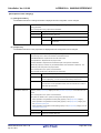
2.5.7
CHAPTER 2 FUNCTIONS
Change the register mode
Select the build tool node on the project tree and select the [Common Options] tab on the Property panel.
Select the register mode to on the [Select register mode] property in the [Register Mode] category.
Figure 2-44. [Select register mode] Property
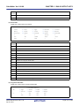
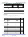
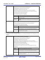
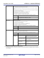
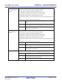
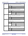
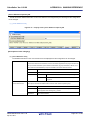
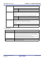
You can select from the following register modes.
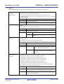
Register Mode
Working Registers
Registers for Register Variables
32-register mode(None) (default)
r10 to r19
r20 to r29
26-register mode(-reg26)
r10 to r16
r23 to r29
22-register mode(-reg22)
r10 to r14
r25 to r29
Remark
See “CubeSuite+ V850 Coding” for details about the register mode.
R20UT0557EJ0100 Rev.1.00
Apr 01, 2011
Page 43 of 782
CubeSuite+ Ver.1.00.00
2.6
CHAPTER 2 FUNCTIONS
Set Assemble Options
To set options for the assembler, select the Build tool node on the project tree and select the [Assemble Options] tab on
the Property panel.
You can set the various assemble options by setting the necessary properties in this tab.
Figure 2-45. Property Panel: [Assemble Options] Tab
Remark
Often used options have been gathered under the [Frequently Used Options(for Assemble)] category on the
[Common Options] tab.
2.6.1
Add an include path
Select the build tool node on the project tree and select the [Assemble Options] tab on the Property panel.
The include path setting is made with the [Additional include paths] property in the [Preprocess] category.
Figure 2-46. [Additional include paths] Property
If you click the [...] button, the Path Edit dialog box will open.
R20UT0557EJ0100 Rev.1.00
Apr 01, 2011
Page 44 of 782
CubeSuite+ Ver.1.00.00
CHAPTER 2 FUNCTIONS
Figure 2-47. Path Edit Dialog Box
Enter an include path per line in [Path(One path per one line)]. You can specify up to 259 characters per line, up to 64
line.
Remark
You can also specify the include path via the [Browse...] button. Select the [Subfolders are automatically
included] check box before clicking the [Browse...] button to add all paths under the specified one (down to
5 levels) to [Path(One path per one line)].
If you click the [OK] button, the entered include paths are displayed as subproperties.
Figure 2-48. [Additional include paths] Property (After Adding Include Paths)
To change the include paths, you can use the [...] button or enter the path directly in the text box of the subproperty.
When the include path is added to the project tree, the path is added to the top of the subproperties automatically.
Remark
You can also set the option in the same way with the [Additional include paths] property in the [Frequently
Used Options(for Assemble)] category on the [Common Options] tab.
R20UT0557EJ0100 Rev.1.00
Apr 01, 2011
Page 45 of 782
CubeSuite+ Ver.1.00.00
2.6.2
CHAPTER 2 FUNCTIONS
Set a macro definition
Select the build tool node on the project tree and select the [Assemble Options] tab on the Property panel.
The macro definition setting is made with the [Macro definition] property in the [Preprocess] category.
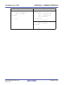
Figure 2-49. [Macro definition] Property
If you click the [...] button, the Text Edit dialog box will open.
Figure 2-50. Text Edit Dialog Box
Enter the macro definition in the format of "macro name=defined value", with one macro name per line. You can
specify up to 31 characters per line, up to 30 line. The "=defined value" part can be omitted, and in this case, "1" is used
as the defined value.
If you click the [OK] button, the entered macro definitions are displayed as subproperties.
Figure 2-51. [Macro definition] Property (After Setting Macros)
To change the macro definitions, you can use the [...] button or enter the path directly in the text box of the subproperty.
Remark
You can also set the option in the same way with the [Macro definition] property in the [Frequently Used
Options(for Assemble)] category on the [Common Options] tab.
R20UT0557EJ0100 Rev.1.00
Apr 01, 2011
Page 46 of 782
CubeSuite+ Ver.1.00.00
2.7
CHAPTER 2 FUNCTIONS
Set Link Options
To set options for the linker, select the Build tool node on the project tree and select the [Link Options] tab on the
Property panel.
You can set the various link options by setting the necessary properties in this tab.
Caution
This tab is not displayed for library projects.
Figure 2-52. Property Panel: [Link Options] Tab
Remark
Often used options have been gathered under the [Frequently Used Options(for Link)] category on the
[Common Options] tab.
R20UT0557EJ0100 Rev.1.00
Apr 01, 2011
Page 47 of 782
CubeSuite+ Ver.1.00.00
2.7.1
CHAPTER 2 FUNCTIONS
Add a user library
Select the build tool node on the project tree and select the [Link Options] tab on the Property panel.
Adding a user library is made with the [Using libraries] property in the [Library] category.
Figure 2-53. [Using libraries] Property
If you click the [...] button, the Text Edit dialog box will open.
Figure 2-54. Text Edit Dialog Box
In the [Text], specify only the "string" part of the library file name "libstring.a" (example: if you specify "user", "libuser.a"
is assumed to be specified). Add one item in one line. You can specify up to 63 characters per line, up to 256 line.
If you click the [OK] button, the entered library files are displayed as subproperties.
Figure 2-55. [Using libraries] Property (After Setting Library Files)
To change the library files, you can use the [...] button or enter the path directly in the text box of the subproperty.
Remark
You can also set the option in the same way with the [Using libraries] property in the [Frequently Used
Options(for Link)] category on the [Common Options] tab.
The library files are searched from the library path. To add a library path, set the [Additional library paths] property.
R20UT0557EJ0100 Rev.1.00
Apr 01, 2011
Page 48 of 782
CubeSuite+ Ver.1.00.00
Caution
CHAPTER 2 FUNCTIONS
Library files can also be linked by adding them directly to the project. In this case, the library files
are not searched from the library paths because they are linked directly via their absolute paths.
R20UT0557EJ0100 Rev.1.00
Apr 01, 2011
Page 49 of 782
CubeSuite+ Ver.1.00.00
2.8
CHAPTER 2 FUNCTIONS
Set ROMization Process Options
To set options for the ROMization processor, select the Build tool node on the project tree and select the [ROMization
Process Options] tab on the Property panel.
You can set the various ROMization processor options by setting the necessary properties in this tab.
Caution
This tab is not displayed for library projects.
Figure 2-56. Property Panel: [ROMization Process Options] Tab
Remark
Often used options have been gathered under the [Frequently Used Options(for ROMization)] category on
the [Common Options] tab.
2.8.1
Create an object for ROMization
The following procedure shows how to create an object for ROMization using the ROMization area reservation code
(rompcrt.o) that is provided as the default object.
The ROMization processor is a tool that takes default value information for variables in data-attribute sections as well
as programs allocated to RAM and packs them into a single section. By default, this section becomes the "rompsec
section". By allocating the rompsec section to ROM and calling the copy function, it is possible to deploy default value
information and programs into RAM.
Remark
See “B.4.3 Creating object for ROMization” for details about the method of creating the ROMization object.
(1) Call a copy function within the application
In the program, specify the section you want to copy from ROM to RAM using the copy function (_rcopy, _rcopy1,
_rcopy2 and _rcopy4).
Specify the label "__S_romp" (label defined in rompcrt.o) which indicates the start address of the rompsec section
as the first argument of the copy function.
Remark
Call the copy function as early as possible in the program, such as within the startup routine or at the
start of the main function.
(2) Create a link directive
During ROMization, a rompsec section is added immediately after the .text section. By allocating the .text section
to the end of ROM in the link directive, the rompsec section up to the end of ROM can be allocated.
(3) Set ROMization process options
Select the build tool node on the project tree and select the [ROMization Process Options] tab on the Property
panel.
R20UT0557EJ0100 Rev.1.00
Apr 01, 2011
Page 50 of 782
CubeSuite+ Ver.1.00.00
CHAPTER 2 FUNCTIONS
(a) Configure the object for ROMization output
To create the object for ROMization, select [Yes(-Xr -lr)] on the [Output ROMized object file] property in the
[Output File] category.
Figure 2-57. [Output ROMized object file] Property
When outputting a ROMized object file, you can set the output folder and output file name.
<1> Set the output folder
Setting the output folder is made with the [Output folder for ROMized object file] property by directly
entering to the text box or by the [...] button. Up to 247 characters can be specified in the text box.
"%BuildModeName%" is set by default. "%BuildModeName%" is an embedded macro. It is replaced to
the build mode name.
<2> Set the output file name
Setting the output file is made with the [ROMized object file name] property by directly entering to the text
box. Up to 259 characters can be specified in the text box. "romp.out" is set by default.
(b) Configure using the standard ROMization area reservation code file
To use the standard ROMization area reservation code file, set the [Use standard ROMization area reservation
code file] property to [Yes] (default).
Figure 2-58. [Use standard ROMization area reservation code file] Property
(4) Run a build
By running a build, the code that specifies "__S_romp" as the label indicating the start address of the rompsec
section is generated, and the ROMization area reservation code (rompcrt.o) and ROMization library that stores the
_rcopy function (libr.a) are linked. Finally, the ROMization object file will be generated from the generated load
module file.
If [Yes] on the [Output hex file] property in the [Output File] category from the [Hex Convert Options] tab on the
Property panel is selected, a hex file is also generated.
Figure 2-59. [Output hex file] Property
R20UT0557EJ0100 Rev.1.00
Apr 01, 2011
Page 51 of 782
CubeSuite+ Ver.1.00.00
2.9
CHAPTER 2 FUNCTIONS
Set Hex Convert Options
To set options for the hex converter, select the Build tool node on the project tree and select the [Hex Convert Options]
tab on the Property panel.
You can set the various hex converter options by setting the necessary properties in this tab.
Caution
This tab is not displayed for library projects.
Figure 2-60. Property Panel: [Hex Convert Options] Tab
Remark
Often used options have been gathered under the [Frequently Used Options(for Hex Convert)] category on
the [Common Options] tab.
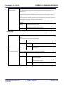
2.9.1
Set the output of a hex file
Select the build tool node on the project tree and select the [Hex Convert Options] tab on the Property panel.
The setting to output a hex file is made with the [Output hex file] property in the [Output File] category. To output a hex
file, select [Yes] (default), to not output a hex file, select [No].
Figure 2-61. [Output hex file] Property
When outputting a hex file, you can set the output folder and output file name.
(1) Set the output folder
Setting the output folder is made with the [Output folder for hex file] property by directly entering to the text box or
by the [...] button. Up to 247 characters can be specified in the text box. "%BuildModeName%" is set by default.
"%BuildModeName%" is an embedded macro. It is replaced to the build mode name.
R20UT0557EJ0100 Rev.1.00
Apr 01, 2011
Page 52 of 782
CubeSuite+ Ver.1.00.00
CHAPTER 2 FUNCTIONS
(2) Set the output file name
Setting the output file is made with the [Hex file name] property by directly entering to the text box. Up to 259
characters can be specified in the text box. "%ProjectName%.hex" is set by default. "%ProjectName%" is an
embedded macro. It is replaced to the project name.
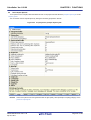
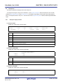
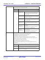
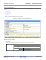
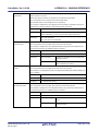
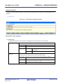
You can also set the format of the hex file.
Select the format on the [Hex file format] property in the [Hex Format] category.
Figure 2-62. [Hex file format] Property
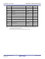
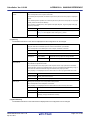
You can select any of the formats below.
Format
Configuration
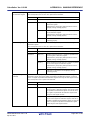
Intel expanded hex format(-fI)
Start address record, expanded address record, data record, and end
(default)
record
Motorola S type format(standard address)(-fS)
S0 record as a header record, S2 record as data record, and S8 record as
end record
Motorola S type format(32-bit address)(-fs)
S0 record as a header record, S3 record as data record, and S7 record as
end record
Expanded Tektronix hex format(-fT)
Remark
2.9.2
Data block, symbol block, and termination block
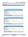
See "3.3 Hex Converter" for details about the hex file format.
Fill the vacant area
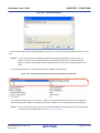
Select the build tool node on the project tree and select the [Hex Convert Options] tab on the Property panel.
The setting to fill the vacant area is made with the [HEX Format] category. If you select [Yes(-U)] on the [Specify
converted address range] property, the [Filling value] property is displayed.
Figure 2-63. [Specify converted address range] and [Filling value] Property
Enter the fill value for the vacant area directly to the text box. The range that can be specified for the value is 0x00 to
0xFF (hexadecimal). "0xFFFF" is set by default.
R20UT0557EJ0100 Rev.1.00
Apr 01, 2011
Page 53 of 782
CubeSuite+ Ver.1.00.00
CHAPTER 2 FUNCTIONS
Set the address range of the area to be converted to a hex file. The range that can be specified for the value is 0x0 to
the maximum value of the address that can be handled by the device (hexadecimal) for the [Start address] property, 0x1
to the maximum value of the address that can be handled by the device (hexadecimal) for the [Size] property. By default,
the start address and size of the internal ROM area defined in the device file are set.
R20UT0557EJ0100 Rev.1.00
Apr 01, 2011
Page 54 of 782
CubeSuite+ Ver.1.00.00
2.10
CHAPTER 2 FUNCTIONS
Set Archive Options
To set options for the archiver, select the Build tool node on the project tree and select the [Archive Options] tab on the
Property panel.
You can set the various archive options by setting the necessary properties in this tab.
Caution
This tab is displayed only for library projects.
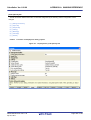
Figure 2-64. Property Panel: [Archive Options] Tab
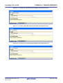
2.10.1
Set the output of an archive file
Select the build tool node on the project tree and select the [Archive Options] tab on the Property panel.
The setting to output an archive file is made with the [Output File] category.
Figure 2-65. [Output File] Category
(1) Set the output folder
Setting the output folder is made with the [Output folder] property by directly entering to the text box or by the [...]
button. Up to 247 characters can be specified in the text box. "%BuildModeName%" is set by default.
"%BuildModeName%" is an embedded macro. It is replaced to the build mode name.
(2) Set the output file name
Setting the output file is made with the [Output file name] property by directly entering to the text box. Up to 259
characters can be specified in the text box. "%ProjectName%.a" is set by default. "%ProjectName%" is an
embedded macro. It is replaced to the project name.
Add "lib" to the head of the output file name, naming the file "lib%ProjectName%.a" so that it can be specified in the
link options.
R20UT0557EJ0100 Rev.1.00
Apr 01, 2011
Page 55 of 782
CubeSuite+ Ver.1.00.00
2.11
CHAPTER 2 FUNCTIONS
Set Section File Generate Options
To set options for the section file generator, select the Build tool node on the project tree and select the [Section File
Generate Options] tab on the Property panel.
You can set the various section file generate options by setting the necessary properties in this tab.
Figure 2-66. Property Panel: [Section File Generate Options] Tab
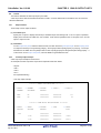
2.11.1
Automatically allocate variables through static analysis
To allocate variables automatically through static analysis, use the section file generator. This tool generates a section
file (a file defining the sections to which external variables are allocated). Variables will be allocated to the specified
sections by performing compilation using that file.
Select the build tool node on the project tree and select the [Section File Generate Options] tab on the Property panel.
In the [Output File] category, set the [Use section file generator] property to [Yes] to generate an empty section file, and
add it to the project (it will also appear in the File node of the project tree). The output destination is the file set in the
[Output folder for section file] property and the [Section file name] property.
Remark
If a section file with the same name already exists, the build will be configured to use it.
Figure 2-67. [Use section file generator] Property
R20UT0557EJ0100 Rev.1.00
Apr 01, 2011
Page 56 of 782
CubeSuite+ Ver.1.00.00
CHAPTER 2 FUNCTIONS
Figure 2-68. Project Tree Panel (After Generating Section File)
Remark
See "3.4 Section File Generator" for details about the format of the section file to be generated.
The settings of the output folder and file of the section file are can be changed.
(1) Set the output folder
Setting the output folder is made with the [Output folder for section file] property by directly entering to the text box
or by the [...] button. Up to 247 characters can be specified in the text box. "%BuildModeName%" is set by default.
"%BuildModeName%" is an embedded macro. It is replaced to the build mode name.
(2) Set the output file name
Setting the output file is made with the [Section file name] property by directly entering to the text box. Up to 259
characters can be specified in the text box. "%ProjectName%.sf" is set by default. "%ProjectName%" is an
embedded macro. It is replaced to the project name.
If this property is changed, an empty section file is generated and added to the project (it will also appear in the File
node of the project tree).
R20UT0557EJ0100 Rev.1.00
Apr 01, 2011
Page 57 of 782
CubeSuite+ Ver.1.00.00
2.12
CHAPTER 2 FUNCTIONS
Set Dump Options
To set options for the dump tool, select the Build tool node on the project tree and select the [Dump Options] tab on the
Property panel.
You can set the various dump options by setting the necessary properties in this tab.
Figure 2-69. Property Panel: [Dump Options] Tab
2.12.1
Use the dump tool
Using the dump tool, you can output information such as the address, attribute, and symbol name of a section/segment
in the object file and archive file.
Select the build tool node on the project tree and select the [Dump Options] tab on the Property panel.
To use the dump tool, select [Yes] on the [Use dump tool] property in the [Dump Tool] category ([No] is selected by
default).
Figure 2-70. [Use dump tool] Property
Remark
2.12.2
See "3.5 Dump Tool " for details about the information output by the dump tool.
Reference the section information
To output section information defined in the input module, use the -h option of the dump tool.
Select the build tool node on the project tree and select the [Dump Options] tab on the Property panel.
Set the -h option in the [Dump Tool] category. If you select [Yes] on the [Use dump tool] property, the [Additional
options for dump tool] property is displayed.
Figure 2-71. [Use dump tool] and [Additional options for dump tool] Property
Specify "-h" on the [Additional options for dump tool] property.
Remark
See "3.5 Dump Tool" for section information to be output.
R20UT0557EJ0100 Rev.1.00
Apr 01, 2011
Page 58 of 782
CubeSuite+ Ver.1.00.00
2.13
CHAPTER 2 FUNCTIONS
Set Cross Reference Options
To set options for the cross reference tool, select the Build tool node on the project tree and select the [Cross
Reference Options] tab on the Property panel.
You can set the various cross reference options by setting the necessary properties in this tab.
Figure 2-72. Property Panel: [Cross Reference Options] Tab
2.13.1
Use the cross reference tool
Using the cross reference tool, you can take all the C source files registered to the project as an input and output all
information (cross reference information, tag jump information, call tree, function metrics and call database) to the files in
text format and CSV format.
Select the build tool node on the project tree and select the [Cross Reference Options] tab on the Property panel.
To use the cross reference tool, select [Yes] on the [Use cross reference tool] property in the [Cross Reference Tool]
category ([No] is selected by default).
Figure 2-73. [Use cross reference tool] Property
Remark
See "3.7 Cross Reference Tool " for details about the information output by the cross reference tool.
R20UT0557EJ0100 Rev.1.00
Apr 01, 2011
Page 59 of 782
CubeSuite+ Ver.1.00.00
2.14
CHAPTER 2 FUNCTIONS
Set Memory Layout Visualization Options
To set options for the memory layout visualization tool, select the Build tool node on the project tree and select the
[Memory Layout Visualization Options] tab on the Property panel.
You can set the various memory layout visualization options by setting the necessary properties in this tab.
Caution
This tab is not displayed for library projects.
Figure 2-74. Property Panel: [Memory Layout Visualization Options] Tab
2.14.1
Use the memory layout visualization tool
Using the memory layout visualization, you can take an object file (*.out) as an input and output a memory map table
(memory map information of variables) to the files in text format and CSV format.
Select the build tool node on the project tree and select the [Memory Layout Visualization Options] tab on the Property
panel.
To use the memory layout visualization tool, select [Yes] on the [Use memory layout visualization tool] property in the
[Memory Layout Visualization Tool] category ([No] is selected by default).
Figure 2-75. [Use memory layout visualization tool] Property
Remark
See "3.8 Memory Layout Visualization Tool" for details about the memory map table.
R20UT0557EJ0100 Rev.1.00
Apr 01, 2011
Page 60 of 782
CubeSuite+ Ver.1.00.00
2.15
CHAPTER 2 FUNCTIONS
Set Build Options Separately
Build options are set at the project or file level.
- Project level: See "2.15.1 Set build options at the project level"
- Project level: See "2.15.2 Set build options at the file level"
2.15.1
Set build options at the project level
To set options for build options for a project (main project or subproject), select the Build tool node on the project tree to
display the Property panel.
Select the component tabs, and set build options by setting the necessary properties.
Compiler: [Compile Options] tab
Assembler: [Assemble Options] tab
Linker: [Link Options] tab
ROMization processor: [ROMization Process Options] tab
Hex converter: [Hex Convert Options] tab
Archiver: [Archive Options] tab
Section file generator: [Section File Generate Options] tab
Dump tool: [Dump Options] tab
Cross reference tool: [Cross Reference Options] tab
Memory layout visualization tool: [Memory Layout Visualization Options] tab
2.15.2
Set build options at the file level
You can individually set compile and assemble options for each source file added to the project.
(1) When setting compile options for a C source file
Select a C source file on the project tree and select the [Build Settings] tab on the Property panel. In the [Build]
category, if you select [Yes] on the [Set individual compile option] property, the message dialog box ("Figure 2-77.
Message Dialog Box") is displayed.
Figure 2-76. [Set individual compile option] Property
Figure 2-77. Message Dialog Box
If you click the [Yes] button in the dialog box, the [Individual Compile Options] tab will be displayed.
R20UT0557EJ0100 Rev.1.00
Apr 01, 2011
Page 61 of 782
CubeSuite+ Ver.1.00.00
CHAPTER 2 FUNCTIONS
Figure 2-78. Property Panel: [Individual Compile Options] Tab
You can set compile options for the C source file by setting the necessary properties in this tab. Note that this tab
takes over the settings of the [Compile Options] tab by default.
(2) When setting assemble options for an assembler source file
Select an assembler source file on the project tree and select the [Build Settings] tab on the Property panel. In the
[Build] category, if you select [Yes] on the [Set individual assemble option] property, the message dialog box
("Figure 2-80. Message Dialog Box") is displayed.
Figure 2-79. [Set individual assemble option] Property
R20UT0557EJ0100 Rev.1.00
Apr 01, 2011
Page 62 of 782
CubeSuite+ Ver.1.00.00
CHAPTER 2 FUNCTIONS
Figure 2-80. Message Dialog Box
If you click the [Yes] button in the dialog box, the [Individual Assemble Options] tab will be displayed.
Figure 2-81. Property Panel: [Individual Assemble Options] Tab
You can set assemble options for the assembler source file by setting the necessary properties in this tab. Note
that this tab takes over the settings of the [Assemble Options] tab by default.
Remark
You can also set assemble options for assembler source files created from C source files. Select a C
source file on the project tree and select the [Individual Compile Options] tab on the Property panel. If
you select [Yes(-Fs)] on the [Output assemble file] property in the [Output File] category, the [Individual
Assemble Options] tab is displayed.
R20UT0557EJ0100 Rev.1.00
Apr 01, 2011
Page 63 of 782
CubeSuite+ Ver.1.00.00
2.16
CHAPTER 2 FUNCTIONS
Prepare for Implementing Boot-flash Relink Function
Depending on the system, in addition to the area which cannot be rewritten/replaced (boot area), there are occasions
when you can use the area which can be rewritten/replaced (flash area), such as the flash or external ROM.
In these kinds of systems, when you wish to change the program in the flash area, a function called the "relink function"
correctly performs function calls between the boot area and flash area without rebuilding the program in the boot area.
By creating load module files for the boot area and flash area, you can implement the relink function. The method to
implement the relink function is shown below.
Remark
2.16.1
See "B.3.3 Boot-flash relink function" for details about the relink function and how to implement it.
Prepare the build target files
(1) Prepare the link directive files
Prepare link directive files for the projects for both the boot area and flash area.
Remark
You can use the same link directive file with the boot area and flash area, but since the description will
become complicated, it is recommend to use a separate link directive file for each area.
(2) Describe the .ext_func quasi directive
Describe the .ext_func quasi directive in the assembler source file.
With the .ext_func directive, specify the ID value for the target function (the actual function exists in the flash area
and is called from the boot area).
Remark
In order to prevent description mistakes and inconsistencies between source files, it is recommend that
you organize the .ext_func directive description in a single file, and regardless of the boot area or flash
area, include that file in all the assembler source files using the .include directive.
2.16.2
Set the boot area project
(1) Create the boot area project
Create a project for the boot area and add the build target files to the project.
Add the startup routine to the Startup node.
R20UT0557EJ0100 Rev.1.00
Apr 01, 2011
Page 64 of 782
CubeSuite+ Ver.1.00.00
CHAPTER 2 FUNCTIONS
Figure 2-82. Boot Area Project
(2) Set the build options for the boot area project
Select the build tool node on the project tree and select the [Common Options] tab on the Property panel. Set the
build options in the [Flash] category.
If you select [Yes] on the [Output flash object file] property, the [Branch table address] property and [Object file
type] property are displayed.
Figure 2-83. [Output flash object file], [Branch table address], and [Object file type] property in Boot Area
Specify the start address of the branch table (address in the flash area) in the [Branch table address] property. The
range that can be specified for the value is 0x0 to 0xffffffff (hexadecimal). "0x0" is set by default.
Also, select [Boot area object file(None)] on the [Object file type] property.
(3) Run a build of the boot area project
When you run a build of the boot area project, a load module file is created.
R20UT0557EJ0100 Rev.1.00
Apr 01, 2011
Page 65 of 782
CubeSuite+ Ver.1.00.00
CHAPTER 2 FUNCTIONS
Figure 2-84. ""Created Files for Boot Area
2.16.3
Set the flash area project
(1) Create the flash area project
Create a project for the boot area and add the build target files to the project.
Add the startup routine to the Startup node.
Figure 2-85. Flash Area Project
R20UT0557EJ0100 Rev.1.00
Apr 01, 2011
Page 66 of 782
CubeSuite+ Ver.1.00.00
CHAPTER 2 FUNCTIONS
(2) Set the build options for the flash area project
Select the build tool node on the project tree and select the [Common Options] tab on the Property panel. Set the
build options in the [Flash] category.
If you select [Yes] on the [Output flash object file] property, the [Branch table address] property and [Object file
type] property are displayed.
Figure 2-86. [Output flash object file], [Branch table address], [Object file type], and [Boot area object file name]
Property
Specify the start address of the branch table (same as the address specified in the boot area project) in the [Branch
table address] property.
If you select [Flash area object file(-Wa, -zf)] on the [Object file type] property, the [Boot area object file name]
property are displayed. Specify the boot area object file.
Caution
Specify an object output by the linker. An error occurs if an object output by the ROMization
processor is specified.
(3) Run a build of the flash area project
When you run a build of the flash area project, a load module file which implements the relink function is created.
Figure 2-87. Created Files for Flash Area
R20UT0557EJ0100 Rev.1.00
Apr 01, 2011
Page 67 of 782
CubeSuite+ Ver.1.00.00
2.17
CHAPTER 2 FUNCTIONS
Make Settings for Build Operations
This section explains operations on a build.
- Set the link order of files
- Change the file build order of subprojects
- Display a list of build options
- Change the file build target project
- Add a build mode
- Change the build mode
- Delete a build mode
- Set the current build options as the standard for the project
2.17.1
Set the link order of files
The link order of object module files and library files is decided automatically, but you can also set the order.
On the project tree, select the Build tool node, and then select [Set Link Order...] from the context menu. The Link
Order dialog box opens.
Figure 2-88. Link Order Dialog Box
The names of the following files are listed in [File] in the order that the files are input to the linker.
- Object module files generated from the source files added to the selected main project or subproject
- Object module files added directly to the project tree of the selected main project or subproject
- Library files added directly to the project tree of the selected main project or subproject
Remark
The default order is the order the files are added to the project.
Object module files created from newly added source files and newly added object module files are added
after the last object module file in the list. Newly added library files are added to the end of the list.
By changing the display order of the files, you can set the input order of the files to the linker.
To change the display order, use the [Up] and [Down] buttons, or drag and drop the file names. After changing the display order, click the [OK] button.
R20UT0557EJ0100 Rev.1.00
Apr 01, 2011
Page 68 of 782
CubeSuite+ Ver.1.00.00
2.17.2
CHAPTER 2 FUNCTIONS
Change the file build order of subprojects
Builds are run in the order of subproject, main project, but when there are multiple subprojects added, the build order of
subprojects is their display order on the project tree.
To change the display order of the subprojects on the project tree, drag the subproject to be moved and drop it on the
desired location.
2.17.3
Display a list of build options
You can display the list of build options set currently on the Property panel for the project (main project and subproject).
If you select [Build Options List] from the [Build] menu, the current settings of the options for the project are displayed
on the [Build Tool] tab from the Output panel in the build order.
Remark
You can change the display format of the build option list.
Select the build tool node on the project tree and select the [Common Options] tab on the Property panel.
Set the [Format of build option list] property in the [Others] category.
Figure 2-89. [Format of build option list] Property
"%FileName% : "%FileName% : %Program% %Options%" is set by default.
"%FileName%", "%Program%", and "%Options%" are embedded macros. They are replaced to the file name
being built, program name under execution, and command line option under build execution.
2.17.4
Change the file build target project
When running a build that targets a specific project (main project or subproject), you must set that project as the "active
project".
To set the active project, select the main project or subproject to be set as the active project on the project tree and
select [Set selected subproject as Active Project] from the context menu.
R20UT0557EJ0100 Rev.1.00
Apr 01, 2011
Page 69 of 782
CubeSuite+ Ver.1.00.00
CHAPTER 2 FUNCTIONS
Figure 2-90. [Set selected project as Active Project] Item
When a project is set as the active project, that project is underlined.
Figure 2-91. Active Project
Remarks 1.
2.
Immediately after creating a project, the main project is the active project.
When you remove a subproject that set as the active project from a project, the main project will be the
active project.
R20UT0557EJ0100 Rev.1.00
Apr 01, 2011
Page 70 of 782
CubeSuite+ Ver.1.00.00
2.17.5
CHAPTER 2 FUNCTIONS
Add a build mode
When you wish to change the build options and macro definitions according to the purpose of the build, you can collectively change those settings. Build options and macro definition settings are organized into what is called "build mode",
and by changing the build mode, you eliminate the necessity of changing the build options and macro definition settings
every time.
The build mode prepared by default is only "DefaultBuild". Add a build mode according to the purpose of the build.
The method to add a build mode is shown below.
(1) Create a new build mode
Creating a new build mode is performed with duplicating an existing build mode.
Select [Build Mode Settings...] from the [Build] menu. The Build Mode Settings dialog box opens.
Figure 2-92. Build Mode Settings Dialog Box
Select the build mode to be duplicated from the build mode list and click the [Duplicate...] button. The Character
String Input dialog box opens.
Figure 2-93. Character String Input Dialog Box
In the dialog box, enter the name of the build mode to be created and then click the [OK] button. The build mode
with that name will be duplicated. The created build mode is added to the build modes of the main project and all
the subprojects which belong to the project.
R20UT0557EJ0100 Rev.1.00
Apr 01, 2011
Page 71 of 782
CubeSuite+ Ver.1.00.00
CHAPTER 2 FUNCTIONS
Figure 2-94. Build Mode Settings Dialog Box (After Adding Build Mode)
(2) Change the build mode
Change the build mode to the newly created build mode (see "2.17.6 Change the build mode").
(3) Change the setting of the build mode
Select the build tool node on the project tree and change the build options and macro definition settings on the
Property panel.
Remark
Creating a build mode is regarded a project change. When closing the project, you will be asked to confirm
whether or not to save the build mode.
R20UT0557EJ0100 Rev.1.00
Apr 01, 2011
Page 72 of 782
CubeSuite+ Ver.1.00.00
2.17.6
CHAPTER 2 FUNCTIONS
Change the build mode
When you wish to change the build options and macro definitions according to the purpose of the build, you can collectively change those settings. Build options and macro definition settings are organized into what is called "build mode",
and by changing the build mode, you eliminate the necessity of changing the build options and macro definition settings
every time.
(1) When changing the build mode for the main project or subprojects
Select the Build tool node of the target project on the project tree and select the [Common Options] tab on the
Property panel. Select the build mode to be changed to on the [Build mode] property in the [Build Mode] category.
Figure 2-95. [Build Mode] Property
(2) When changing the build mode for the entire project
Select [Build Mode Settings...] from the [Build] menu. The Build Mode Settings dialog box opens.
Figure 2-96. Build Mode Settings Dialog Box
If you select the build mode to be changed from the build mode list, the selected build mode is displayed in
[Selected build mode]. If you click the [Apply to All] button, the build mode for the main project and all the subprojects which belong to the project will be changed to the build mode selected in the dialog box.
Caution
For projects that the selected build mode does not exist, the build mode is duplicated from
"DefaultBuild" with the selected build mode name, and the build mode is changed to the duplicated build mode.
Remarks 1.
The build mode prepared by default is only "DefaultBuild". See "2.17.5 Add a build mode" for the
method of adding a build mode.
2.
You can change the name of the build mode by selecting the build mode from the build mode list and
clicking the [Rename...] button. However, you cannot change the name of "DefaultBuild".
R20UT0557EJ0100 Rev.1.00
Apr 01, 2011
Page 73 of 782
CubeSuite+ Ver.1.00.00
2.17.7
CHAPTER 2 FUNCTIONS
Delete a build mode
Deleting a build mode is performed with the Build Mode Settings dialog box.
Select [Build Mode Settings...] from the [Build] menu. The dialog box opens.
Figure 2-97. Build Mode Settings Dialog Box
Select the build mode to be deleted from the build mode list and click the [Delete] button. The Message dialog box
below opens.
Figure 2-98. Message Dialog Box
To continue with the operation, click the [OK] button in the dialog box.
The selected build mode is deleted from the project.
Caution
You cannot delete "DefaultBuild".
R20UT0557EJ0100 Rev.1.00
Apr 01, 2011
Page 74 of 782
CubeSuite+ Ver.1.00.00
2.17.8
CHAPTER 2 FUNCTIONS
Set the current build options as the standard for the project
On the Property panel, if you add a change to the settings for the standard build options, the value of the property will
be displayed in boldface.
Figure 2-99. Property Panel (After Changing Standard Build Option)
To make the build options for the currently selected project (main project or subproject) the standard build options
(remove the boldface), select the Build tool node on the project tree and select [Set to Default Build Option for Project]
from the context menu.
Figure 2-100. [Set to Default Build Option for Project] Item
The value of the properties after setting them as the standard build option are as shown below.
Figure 2-101. Property Panel (After Setting Standard Build Option)
Caution
When the main project is selected, only the main project settings are made. Even if subprojects are
added, their settings are not made.
R20UT0557EJ0100 Rev.1.00
Apr 01, 2011
Page 75 of 782
CubeSuite+ Ver.1.00.00
2.18
CHAPTER 2 FUNCTIONS
Run a Build
This section explains operations related to running a build.
(1) Build types
The following types of builds are available.
Table 2-1. Build Types
Type
Build
Description
Out of build target files, runs a build of only updated files.
See "2.18.1 Run a build of updated files".
Rebuild
Runs a build of all build target files.
See "2.18.2 Run a build of all files".
Rapid build
Runs a build in parallel with other operations.
See "2.18.3 Run a build in parallel with other operations".
Batch build
Runs builds in batch with the build modes that the project has.
See "2.18.4 Run builds in batch with build modes".
Remarks 1.
Builds are run in the order of subproject, main project.
Subprojects are built in the order that they are displayed on the project tree (see "2.17.2 Change
the file build order of subprojects").
2.
If there are files being edited with the Editor panel when running a build, rebuild, or batch build,
then all these files are saved.
(2) Display execution results
The execution results of the build (output messages of the build tool) are displayed in each tab on the Output
panel.
- Build, rebuild, or batch build: [All Messages] tab and [Build Tool] tab
- Rapid build: [Rapid Build] tab
Figure 2-102. Build Execution Results (Build, Rebuild, or Batch Build)
R20UT0557EJ0100 Rev.1.00
Apr 01, 2011
Page 76 of 782
CubeSuite+ Ver.1.00.00
CHAPTER 2 FUNCTIONS
Figure 2-103. Build Execution Results (Rapid Build)
Remarks 1.
2.
The text in the [Rapid Build] tab becomes dimmed.
When a file name or line number can be obtained from the output messages, if you double click on
the message, you can jump to the relevant line in the file.
3.
If you press the [F1] key when the cursor is on a line displaying the warning or error message, you
can display the help related to that line's message.
Files generated by the build tool appear on the Project Tree panel, under the Build tool generated files node.
Figure 2-104. Build Tool Generated Files
Remark
Files displayed under the Build tool generated files node are as follows.
- For other than library projects
Load module file (*.out)
Link map file (*.map)
Hex file (*.hex)
Dump list (dump.txt)
Cross reference information (cxref)
Tag information (ctags)
Call tree information (ccalltre.csv, ccalltre.lst)
Function metrics information (cmeasure.csv, cmeasure.lst)
Call database information (cprofile.csv, cprofile.dat)
Memory map table (rammap.csv)
R20UT0557EJ0100 Rev.1.00
Apr 01, 2011
Page 77 of 782
CubeSuite+ Ver.1.00.00
CHAPTER 2 FUNCTIONS
- For library projects
Archive file (*.a)
Dump list (dump.txt)
Cross reference information (cxref)
Tag information (ctags)
Call tree information (ccalltre.csv, ccalltre.lst)
Function metrics information (cmeasure.csv, cmeasure.lst)
Call database information (cprofile.csv, cprofile.dat)
Caution
The Build tool generated files node is created during build.
This node will no longer appear if you reload the project after building.
2.18.1
Run a build of updated files
Out of build target files, run a build of only updated files (hereafter referred to as "build").
Running a build is performed for the entire project (main project and subprojects) or active project (see "2.17.4
Change the file build target project").
(1) When running a build of the entire project
Click
on the toolbar.
(2) When running a build of the active project
Select the project, and then select [Build active project] from the context menu.
Figure 2-105. [Build active project] Item
Remark
If the included source files are not built after editing the header file and running the build, update the file
dependencies (see "2.3.8 Update file dependencies").
R20UT0557EJ0100 Rev.1.00
Apr 01, 2011
Page 78 of 782
CubeSuite+ Ver.1.00.00
2.18.2
CHAPTER 2 FUNCTIONS
Run a build of all files
Run a build of all build target files (hereafter referred to as "rebuild").
Running a rebuild is performed for the entire project (main project and subprojects) or active project (see "2.17.4
Change the file build target project").
(1) When running a rebuild of the entire project
Click
on the toolbar.
(2) When running a rebuild of the active project
Select the project, and then select [Rebuild active project] from the context menu.
Figure 2-106. [Rebuild active project] Item
2.18.3
Run a build in parallel with other operations
CubeSuite+ has a function that a build is started automatically when one of the following events occurs (hereafter
referred to as "rapid build").
- When C source files, assembler source files, header files, link directive file, section file, object module file, or
library file that has been added to the project are updated
- When a build target file has been added to or removed from the project
- When the link order of object module files and library files has changed
- When the properties of the build tool or build target files are changed
(except, however, when the properties of [Dump Options] tab, [Cross Reference Options] tab, and [Memory Layout
Visualization Options] tab are changed)
If a rapid build is enabled, it is possible to perform a build in parallel with the above operations.
To enable/disable a rapid build, select [Rapid Build] from the [Build] menu. A rapid build is enabled by default.
R20UT0557EJ0100 Rev.1.00
Apr 01, 2011
Page 79 of 782
CubeSuite+ Ver.1.00.00
CHAPTER 2 FUNCTIONS
Figure 2-107. [Rapid Build] Item (When Rapid Build Is Valid)
Figure 2-108. [Rapid Build] Item (When Rapid Build Is Invalid)
Remarks 1.
Caution
After editing source files, it is recommend to save frequently by pressing the [Ctrl] + [S] key.
2.
Enabling/disabling a rapid build is set for the entire project (main project and subprojects).
3.
If you disable a rapid build while it is running, it will be stopped at that time.
This function is valid only when editing source files with the Editor panel.
R20UT0557EJ0100 Rev.1.00
Apr 01, 2011
Page 80 of 782
CubeSuite+ Ver.1.00.00
2.18.4
CHAPTER 2 FUNCTIONS
Run builds in batch with build modes
You can run builds, rebuilds and cleans in batch with the build modes that the project (main project and subproject) has
(hereafter referred to as "batch build").
Remark
See the sections below for a build, rebuild, and clean.
- Build: See "2.18.1 Run a build of updated files".
- Rebuild: See "2.18.2 Run a build of all files".
- Clean: See "2.18.8 Delete intermediate files and generated files".
Select [Batch Build] from the [Build] menu. The Batch Build dialog box opens.
Figure 2-109. Batch Build Dialog Box
In the dialog box, the list of the combinations of the names of the main project and subprojects in the currently opened
project and their build modes and macro definitions is displayed.
Select the check boxes for the combinations of the main project and subprojects and build modes that you wish to run
a batch build, and then click the [Build], [Rebuild], or [Clean] button.
Remark
The batch build order follows the project build order, the order of the subprojects, main project.
When multiple build modes are selected for a single main project or subproject, after running builds of the
subproject with all the selected build modes, the build of the next subproject or main project is run.
R20UT0557EJ0100 Rev.1.00
Apr 01, 2011
Page 81 of 782
CubeSuite+ Ver.1.00.00
2.18.5
CHAPTER 2 FUNCTIONS
Compile/assemble individual files
You can just compile or assemble for each source file added to the project.
(1) When compiling a C source file
Select a C source file on the project tree and select the [Compile] from the context menu.
Figure 2-110. [Compile] Item
(2) When assembling an assembler source file
Select an assembler source file on the project tree and select the [Assemble] from the context menu.
Figure 2-111. [Assemble] Item
R20UT0557EJ0100 Rev.1.00
Apr 01, 2011
Page 82 of 782
CubeSuite+ Ver.1.00.00
2.18.6
CHAPTER 2 FUNCTIONS
Stop running a build
To stop running a build, rebuild, or batch build, click
2.18.7
on the toolbar.
Save the build results to a file
You can save the execution results of the build (output messages of the build tool) that displayed on the Output panel.
Select the [Build Tool] tab on the panel, and then select [Save Output - Build Tool As...] from the [File] menu. The Save
As dialog box opens.
Figure 2-112. Save As Dialog Box
In the dialog box, specify the file to be saved and then click the [Save] button.
2.18.8
Delete intermediate files and generated files
You can delete all the intermediate files and generated files output by running a build (hereafter referred to as "clean").
Running a clean is performed for the entire project (main project and subprojects) or active project (see "2.17.4
Change the file build target project").
R20UT0557EJ0100 Rev.1.00
Apr 01, 2011
Page 83 of 782
CubeSuite+ Ver.1.00.00
CHAPTER 2 FUNCTIONS
(1) When running a clean of the entire project
From the [Build] menu, select [Clean Project].
Figure 2-113. [Clean Project] Item
(2) When running a clean of the active project
Select the project, and then select [Clean active project] from the context menu.
Figure 2-114. [Clean active project] Item
R20UT0557EJ0100 Rev.1.00
Apr 01, 2011
Page 84 of 782
CubeSuite+ Ver.1.00.00
2.19
CHAPTER 2 FUNCTIONS
Estimate the Stack Capacity
To estimate the stack capacity, use the the stack usage tracer.
The stack usage tracer performs a static analysis, and displays the functions called by a function in a tree format, as
well as stack information for each function (function name, total stack size, frame size, additional margin, and file name)
in list format.
2.19.1
Starting and exiting
To start the stack usage tracer, from the Main window, select the [Tool] menu >> [Startup Stack Usage Tracer].
After the stack usage tracer finishes starting up, it will display the function call relationship and stack information for
each function in the tree display area/list display area of the Stack Usage Tracer window.
Figure 2-115. Starting Up Stack Usage Tracer
To exit the stack usage tracer, from the Stack Usage Tracer window, select [File] menu >> [Exit sk850].
R20UT0557EJ0100 Rev.1.00
Apr 01, 2011
Page 85 of 782
CubeSuite+ Ver.1.00.00
2.19.2
CHAPTER 2 FUNCTIONS
Check the call relationship
You can check the function-call relationship in the tree display area of the Stack Usage Tracer window.
Figure 2-116. Tree Display Area
Remark
The table below shows the meaning of the icon displayed to the left of the string representing the function
name.
The display priority for icons is from High:
to Low:
.
The function directly called by a given function with the largest total stack size
Information (additional margin, recursion depth, or callee functions) has been modified via the Adjust Stack
Size dialog box or a stack size specification file
Recursive function
The stack usage tracer has not acquired any stack information for this function
Other than the above
R20UT0557EJ0100 Rev.1.00
Apr 01, 2011
Page 86 of 782
CubeSuite+ Ver.1.00.00
2.19.3
CHAPTER 2 FUNCTIONS
Check the stack information
You can check the stack information (function name, total stack size, frame size, additional margin, and file name) from
the list display area of the Stack Usage Tracer window.
- Total stack size (including stack size of callee functions)
- Frame size (not including stack size of callee functions)
- Additional margin (value mandatorily added to frame size)
Figure 2-117. List Display Area
Remark
If you make changes to the project that will affect the total stack size while the stack usage tracer is running
(e.g. you edit the files in your project so that the total stack size changes), then after rebuilding the project,
click
to update the display.
R20UT0557EJ0100 Rev.1.00
Apr 01, 2011
Page 87 of 782
CubeSuite+ Ver.1.00.00
2.19.4
CHAPTER 2 FUNCTIONS
Check unknown functions
You can check functions for which the stack usage tracer could not obtain stack information in the Stack Size Unknown
/ Adjusted Function Lists dialog box, under [Unknown Functions].
Figure 2-118. Stack Size Unknown / Adjusted Function Lists Dialog Box
Remark
Functions will appear under [Unknown Functions] in the following circumstances.
- The frame size could not be measured.
- A recursive function for which the recursion depth has not been set in the Adjust Stack Size dialog box.
- The function includes indirect function calls which are not set as callee functions in the Adjust Stack Size
dialog box.
R20UT0557EJ0100 Rev.1.00
Apr 01, 2011
Page 88 of 782
CubeSuite+ Ver.1.00.00
2.19.5
CHAPTER 2 FUNCTIONS
Change the frame size
You can dynamically change the frame size of functions for which the stack usage tracer was not able to obtain stack
information, or for functions that you intentionally want to modify, using the Adjust Stack Size dialog box or a stack size
specification file.
(1) Using the Adjust Stack Size dialog box
The procedure for using the Adjust Stack Size dialog box is as follows.
- Select the desired item in the tree display area of the Stack Usage Tracer window, then click toolbar >>
.
The Adjust Stack Size dialog box opens.
Figure 2-119. Adjust Stack Size Dialog Box
- After setting [Additional Margin], [Recursion Depth], and [Callee Functions], click the [OK] button.
R20UT0557EJ0100 Rev.1.00
Apr 01, 2011
Page 89 of 782
CubeSuite+ Ver.1.00.00
CHAPTER 2 FUNCTIONS
(2) Using a stack size specification file
Below is the procedure for using a stack size specification file.
- Create a stack size specification file
Write the functions in the stack size specification file that you would like to set dynamically, using the following
format.
function name [, ADD=additional margin] [, RECTIME=recursion depth] [, CALL=callee function] ...
Figure 2-120. Sample Stack Size Specification File
# Set the frame size of function "_flib" written in assembly
# language to 50
[flib], ADD=50
# Set the frame size of function "sub2" written in C to 100
sub2, ADD=100
#Set the recursion depth of recursive function "sub3" written
# in C to 123
sub3, RECTIME=123
- From the Stack Usage Tracer window, select [File] menu >> [Load Stack Size Specification File...]. The Open
dialog box opens. Specify the stack size specification file, then click the [Open] button.
R20UT0557EJ0100 Rev.1.00
Apr 01, 2011
Page 90 of 782
CubeSuite+ Ver.1.00.00
CHAPTER 3 BUILD OUTPUT LISTS
CHAPTER 3 BUILD OUTPUT LISTS
This chapter describes format and other aspects of lists output by the build via various commands.
3.1
Assembler
This section describes the assemble list. An assemble list is a list-formatted version of the code that is produced when
the source has been compiled and assembled. It can be used to check the code resulting from compilation and
assembly.
Remark
3.1.1
See "B.2.1 I/O files" for details about input and output files of the assembler.
Output method
The assemble list can be output as follows.
(1) Command input
When the -a option has been specified, the assemble list is output via standard output. If the -a option is specified
along with the -I option which specifies an output file name, the assemble list is output to the specified file.
When using the C compiler to compile the C source, if the "output assemble list" has been specified along with
"output source comment" (via the -Xc option), the C source line that corresponds to the code appears as
comments in the assemble list.
However, the code line and source line may not correspond if optimization has been forced.
(2) CubeSuite+
On the Project Tree panel, select the Build tool node, and then select the [Assemble Options] tab on the Property
panel. To output the assemble list file, in the [Assemble List] category, set the [Output assemble list file] property to
[Yes(-a -l)]. The output destination is the folder set in the [Output folder for assemble list file] property.
The list is output to a file, and the file name extension is changed to ".v".
When compiling the C source, open the [Compile Options] tab , then in the [Output File] category, set the [Output
assemble list file] property to [Yes(-Fv)]. And then, in the [Output Code] category, set the [Output comment to
assembly language source file] property to [Yes(-Xc)]. The C source line that corresponds to the code appears as
comments in the assemble list.
However, the code line and source line may not correspond if optimization has been forced.
3.1.2
Output example
An assemble list output example is shown below.
An example of the assemble list that is output by compiling the C source in the example and then assembling the
output assembler source file.
- C source file
void main(void)
{
int
a;
}
R20UT0557EJ0100 Rev.1.00
Apr 01, 2011
Page 91 of 782
CubeSuite+ Ver.1.00.00
CHAPTER 3 BUILD OUTPUT LISTS
- Output assemble list
(1)
(2)
(3)
(4)
(5)
:
A-X- 00000000
41
.file “c:\work\src\a.c“
A-X- 00000000
42
.align 4
A-X- 00000000
43
#@BF
A-X- 00000000
44
.frame _main, .s2
A-X- 00000000
45
.globl _main
A-X- 00000000
46
A-X- 00000000
47
#@B_PROLOGUE
A-X- 00000000 D505
48
jbr
A-X- 00000002
49
.L16:
A-X- 00000002
50
.G17:
A-X- 00000002
51
.G18:
A-X- 00000002
52
.G9:
A-X- 00000002
53
.G11:
A-X- 00000002
54
.G19:
A-X- 00000002
55
#@B_EPILOGUE
A-X- 00000002 23FF0100
56
ld.w
-4+.F2[sp], lp
A-X- 00000006 441A
57
add
.S2, sp
A-X- 00000008 7F00
58
jmp
[lp]
A-X- 0000000A
59
A-X- 0000000A
60
A-X- 0000000A 5C1A
61
add
-.S2, sp
A-X- 0000000C 63FF0100
62
st.w
lp, -4+.F2[sp]
A-X- 00000010
63
#@E_EPILOGUE
A-X- 00000010 95F0
64
jbr
A-X- 00000012
65
#@FUNC_ARG
A-X- 00000012
66
A-X- 00000012
67
.set
.S2, 0x4
A-X- 00000012
68
.set
.F2, 0x4
A-X- 00000012
69
.set
.A2, 0x0
A-X- 00000012
70
.set
.T2, 0x0
A-X- 00000012
71
.set
.P2, 0x0
A-X- 00000012
72
.set
.R2, 0x0
A-X- 00000012
73
.set
.X2, 0x0
_main:
.L15
--0
#@E_EPILOGUE
.L15:
.L16
.G5:
:
R20UT0557EJ0100 Rev.1.00
Apr 01, 2011
Page 92 of 782
CubeSuite+ Ver.1.00.00
Item
CHAPTER 3 BUILD OUTPUT LISTS
Description
Number
(1)
Section attribute
These are section attributes for sections stored in the corresponding line.
Section attributes and their meanings are as follows.
A: Section occupying memory
W: Section that can be written
X: Executable section
G: Section allocated to memory area that can be referenced by using global pointer (gp) and 16-bit
displacement
(2)
Location counter value
This is the location counter value for the beginning of the line of code.
(3)
Code
This is the code, expressed as a hexadecimal number.
(4)
Line number
This is the line number, expressed as a decimal number.
(5)
Source program
This is the assembly language source program on the line. If instruction expansion is executed for the
instruction on that line, the instruction string resulting from the instruction expansion is indicated following --.
The C source program corresponding to that line's assembly source program is also displayed in this area.
R20UT0557EJ0100 Rev.1.00
Apr 01, 2011
Page 93 of 782
CubeSuite+ Ver.1.00.00
3.2
CHAPTER 3 BUILD OUTPUT LISTS
Linker
This section describes the link map output by the linker.
A link map is where link result-related information is written. It can be referenced for information such as a section's
allocation addresses.
3.2.1
Output method
The link map can be output as follows.
(1) Command input
Specify the -m option to display the link map in standard output when linking ends. If the -mo option is specified,
display in the old format of CA850 Ver. 2.60 or earlier. A file name is specified as the -m=file option or the -mo=file
option to output to a file.
(2) CubeSuite+
On the Project Tree panel, select the Build tool node, and then select the [Link Options] tab on the Property panel.
To output the link map, in the [Link Map] category, set the [Output link map file] property to [Yes(-m)]. The output
destination is the folder set in the [Output folder for link map file] property and the [link map file name] property . It
is also shown on the Project Tree panel, under the Build tool generated files node.
3.2.2
Link map output example
A link map output example is shown below.
An example of the link map that is output when object files have been linked.
- Objects
crtN.o
main.o
func.o
libc.a (standard library)
- Link map output example
********** MEMORY ALLOCATION MAP **********
(1)OUTPUT
(2)SEGMENT
(3)VIRTUAL
(4)SIZE(16)
(5)SIZE(10)
SEGMENT
ATTRIBUTE
ADDRESS
TEXT
RX
0x00000000
0x00000082
130
DATA
RW
0x00000088
0x00000018
24
********** LINK EDITOR ALLOCATION MAP **********
(6)OUTPUT
SECTION
(7)INPUT
SECTION
.text
(8)VIRTUAL
(9)SIZE
ADDRESS
(10)INPUT
FILE
0x00000000
0x00000082
.text
0x00000000
0x0000001a
crtN.o
.text
0x0000001c
0x0000002c
main.o
R20UT0557EJ0100 Rev.1.00
Apr 01, 2011
Page 94 of 782
CubeSuite+ Ver.1.00.00
CHAPTER 3 BUILD OUTPUT LISTS
.text
0x00000048
0x00000018
func.o
.text
0x00000060
0x00000022
strcmp.o(..\lib850\
0x00000088
0x0000000e
0x00000088
0x0000000e
0x00000098
0x00000008
.sbss
0x00000098
0x00000004
func.o
.sbss
0x0000009c
0x00000004
*(GpCommon)*
.sdata
.sdata
.sbss
Item
main.o
Description
Number
(1)
Output segment
Names of output segments configuring the object file to be generated (names of the output segments are not
stored in the generated object file)
(2)
Segment attribute
R: Read
W: Write
X: Executable
(3)
Address
Start address of the output segment
(4)
Size (hexadecimal)
Size of the memory including the alignment conditions between sections and the align hole (hexadecimal)
(5)
Size (decimal)
Size of the memory including the alignment conditions between sections and the align hole (decimal)
(6)
Output section
Section name output to the load module (displayed up to 12 characters)
(7)
Input section
Name of input section configuring output section (displayed up to 12 characters)
(8)
Address
The start address of output section or input section
(9)
Size
Size of output section or input section
(10)
Input file
Object file names belonging to an input section
If an area is allocated by using the .comm quasi directive, the area is common to all the files, and its section is
displayed as "*(Common)*" or "*(GpCommon)*". If the object file to which the input section belongs is an object file in an
archive file (library), the archive file is displayed in the following format.
- Object file name (archive file name)
If display in the old format of CA850 Ver. 2.60 or earlier is specified by using the -mo option, *(nil)* is displayed for the
section created with the linker, and sections created with the assembler such as .symtab, .strtab, and.shstrtab.
Remark
*(nil)*
*(nil)* may appear in the data areas of the .sbss and .sdata sections. This indicates that a globally declared
variable without an initial value has been allocated. Even if a variable with the same name is used for a
R20UT0557EJ0100 Rev.1.00
Apr 01, 2011
Page 95 of 782
CubeSuite+ Ver.1.00.00
CHAPTER 3 BUILD OUTPUT LISTS
different file, it is still inevitably part of the load module, so the file name containing the variable becomes
undefined and therefore appears as *(nil)* in the link map.
However, if data without an initial value was declared using the #pragma section "data" instruction, the file
name appears instead of *(nil)* since the file's allocation is identified.
R20UT0557EJ0100 Rev.1.00
Apr 01, 2011
Page 96 of 782
CubeSuite+ Ver.1.00.00
3.3
CHAPTER 3 BUILD OUTPUT LISTS
Hex Converter
This section describes the hx850 output file formats.
To configure the hex file output in CubeSuite+, on the Project Tree panel, select the Build tool node, then on the
Property panel, make the settings from the [Hex Convert Options] tab.
In the [Output File] category, set the [Output hex file] property to [Yes]. The output destination is the folder set in the
[Output folder for hex file] property and the [Hex file name] property . The setting for the output file format is performed in
the [Hex file format] property in the [Hex Format] category. The Hex file is also shown on the Project Tree panel, under
the Build tool generated files node.
Remark
3.3.1
See "B.5.1 I/O files" for details about input and output files of the hex converter.
Intel expanded
Intel expanded hex format files, which consist of four recordsNote: the start address record, expanded address record,
data record, and end record
Note Each record is output in ASCII code.
The following figure shows a file configuration in Intel expanded hex format.
Figure 3-1. File Configuration in Intel Expanded Hex Format
Start address record
Expanded address recordNote
Data recordNote
:
Data record
Expanded address record
Data record
:
Data record
End record
Note The expanded address record and data record are repeated.
Each record consists of the following fields.
:
CC
(1)
(2)
AAAA
(3)
Item
TT
(4)
[field]...
SS
NL
(5)
(6)
Description
Number
(1)
(2)
Record mark
Number of bytes
number of bytes expressed as 2-digit hexadecimal numbers of [field]...
R20UT0557EJ0100 Rev.1.00
Apr 01, 2011
Page 97 of 782
CubeSuite+ Ver.1.00.00
CHAPTER 3 BUILD OUTPUT LISTS
Item
Description
Number
(3)
Location address
(4)
Record type
03: Start address record, 02: Expanded address record, 00: Data record, 01: End record
(5)
Checksum
The value expressed as 2-digit hexadecimal number in records (other than :, SS, and NL) sequentially subtracted
from initial value 0 and that lower 1 byte expressed as a 2-digit hexadecimal number
(6)
New line (\n)
- Start address record
This record indicates an entry point address.
:
04
0000
(1)
(2)
03
(3)
PPPP
OOOO
(4)
(5)
Item
SS
NL
Description
Number
(1)
Number of bytes
Fixed at 04
(2)
Fixed at 0000
(3)
Record type
03
(4)
Paragraph value of entry point addressNote
(5)
Offset value of entry point address
Note The address is calculated by (paragraph value << 4) + offset value.
- Expanded address record
This record indicates the paragraph value of a load addressNote.
Note The value is output if the segment is renewed at the beginning of a segment (when the data record is
output) or when the offset value of the data record's load address exceeds the maximum value of 0xffff.
:
02
0000
(1)
(2)
Item
02
(3)
PPPP
SS
NL
(4)
Description
Number
(1)
Number of bytes
Fixed at 02
(2)
(3)
Fixed at 0000
Record type
02
R20UT0557EJ0100 Rev.1.00
Apr 01, 2011
Page 98 of 782
CubeSuite+ Ver.1.00.00
CHAPTER 3 BUILD OUTPUT LISTS
Item
Description
Number
(4)
Paragraph value of segment
- Data record
This record indicates the value of a code.
:
CC
AAAA
(1)
00
(2)
DD...DD
(3)
SS
NL
(4)
Item
Description
Number
(1)
Number of bytesNote
(2)
Location address
(3)
Record type
00
(4)
Code
Each byte of code expressed as 2-digit hexadecimal number
Note This is limited to the range of 0x1 to 0xff (the minimum value for the number of bytes of code indicated by
one data record is 1 and the maximum value is 255).
Example
:
04
0100
(1)
00
(2)
3C58E01B
(3)
(4)
Item
6C
NL
(5)
Description
Number
(1)
Number of bytes of 3C58E01B expressed as 2-digit hexadecimal number
(2)
Location address
(3)
Record type
00
(4)
Code
Each byte of code expressed as 2-digit hexadecimal number
(5)
Checksum
The lower 1 byte of two's complement E6C of 04 + 01 + 00 + 00 + 3C + 58 + E0 + 1B = 194 is expressed
as a 2-digit hexadecimal number.
- End record
This record indicates the end of a code.
:
00
(1)
0000
(2)
R20UT0557EJ0100 Rev.1.00
Apr 01, 2011
01
FF
(3)
(4)
NL
Page 99 of 782
CubeSuite+ Ver.1.00.00
CHAPTER 3 BUILD OUTPUT LISTS
Item
Description
Number
(1)
Number of bytes
Fixed at 00
(2)
Fixed at 0000
(3)
Record type
01
(4)
Checksum
Fixed at FF
Remark
Intel hex
An allocation address in the Intel hex format is 2 bytes (16 bits). Therefore, only a 64 KB space can be
directly specified. To extend this area, the Intel extended hex format adds an extension address of 16 bits
so that a space up to 1 M byte (20 bits) can be used.
Specifically, a record type that specifies a 16-bit extension address is added. This extension address is
shifted 4 bits and added to the allocation address to express a 20-bit address.
To indicate FFFFFH, for example, F000H is set as the extension address, and FFFFH is specified as the
location address.
In the Intel extended hex format, only 0 to FFFFFH can be addressed. To express 100000H, another object
format must be used.
The hex converter outputs a message if the rule of this format is violated with this address and size used.
In the Intel extended hex format, a value that can be expressed is 20 bits, or 1 M byte (0x100000).
W8737 : The start address of convert area exceeds the maximum value of the address
that can be expressed in the Intel expanded hex format
If the message "W8737" is output, the start address of the area to be converted into the hex format
exceeds 1 M byte.
W8735: The address of convert area exceeds the maximum value of the address that
can be expressed in the Intel expanded hex format
If the message "W8735" is output, the address to be converted into the hex format exceeds 1 M byte (20
bits).
The above error occurs in the following cases even if 1 M byte is not exceeded.
Examples 1.
An offset that starts from the address specified by the -d option is not used
-> The absolute address is stored in the hex format.
2.
A section is allocated in the vicinity of the upper limit of the address that can be
expressed by 20 bits
-> The start address fits in 20 bits, but 20 bits are exceeded in the middle of the section.
If these two patterns are satisfied, the message "W8735" is output even if the area to be converted is as
small as 4 bytes.
R20UT0557EJ0100 Rev.1.00
Apr 01, 2011
Page 100 of 782
CubeSuite+ Ver.1.00.00
3.3.2
CHAPTER 3 BUILD OUTPUT LISTS
Motorola S type
A file in the Motorola S type hex format consists of five recordsNote 1: S0 record as a header record, S2/S3 records as
data records, and S8/S7 records as end recordsNote 2.
The following figure shows the file configuration of the Motorola S type hex format.
Notes 1.
Each record is output in ASCII code.
2.
The Motorola S type hex formats are divided into two types: (24-bit) standard address and 32-bit address
types. The format of the standard address type consists of S0, S2, and S8 records, and the format of the 32bit address type consists of S0, S3, and S7 records.
Figure 3-2. File Configuration of Motorola S Type Hex Format
S0 record
S2/S3 record
:
S2/S3 record
S8/S7 record
Each record consists of the following fields.
ST
LL
(1)
(2)
field [field]...
SS
NL
(3)
(4)
Item
Description
Number
(1)
Record type
(2)
Record length
field (number of bytes expressed as 2-digit hexadecimal numbers of [field]...) + number of bytes expressed by
SSNote
(3)
Checksum
Lower 1 byte expressed as 2-digit hexadecimal number of one's complement of total of number of bytes in records
(other than ST, SS, and NL) expressed as 2-digit hexadecimal number
(4)
New line (\)
Note This is 1.
- S0 record
This record indicates a file name.
S0
LL
FF...FF
(1)
SS
NL
(2)
Item
Description
Number
(1)
Record type
S0
R20UT0557EJ0100 Rev.1.00
Apr 01, 2011
Page 101 of 782
CubeSuite+ Ver.1.00.00
CHAPTER 3 BUILD OUTPUT LISTS
Item
Description
Number
(2)
File name
Specified file name indicated in ASCII code
- S2 record
This record indicates the value of a code.
S2
LL
AAAAAA
(1)
DD...DD
(2)
SS
NL
(3)
Item
Description
Number
(1)
Record type
S2
(2)
Load address
24 bitsNote
(3)
Code
Each byte of code expressed as 2-digit hexadecimal number
Note The range is 0x0 to 0xffffff.
- S3 record
This record indicates the value of a code.
S3
LL
AAAAAAAA
(1)
(2)
DD...DD
SS
NL
(3)
Item
Description
Number
(1)
Record type
S3
(2)
Load address
32 bitsNote
(3)
Code
Each byte of code expressed as 2-digit hexadecimal number
Note The range is 0x0 to 0xffffffff.
- S7 record
This record indicates an entry point address.
S7
(1)
LL
AAAAAAAA
SS
NL
(2)
R20UT0557EJ0100 Rev.1.00
Apr 01, 2011
Page 102 of 782
CubeSuite+ Ver.1.00.00
CHAPTER 3 BUILD OUTPUT LISTS
Item
Description
Number
(1)
Record type
S7
(2)
Entry point address
32 bitsNote
Note The range is 0x0 to 0xffffffff.
- S8 record
This record indicates an entry point address.
S8
LL
AAAAAA
(1)
SS
NL
(2)
Item
Description
Number
(1)
Record type
S8
(2)
Entry point address
24 bitsNote
Note The range is 0x0 to 0xffffff.
3.3.3
Expanded tektronix
A file in the expanded tektronix hex format consists of three types of blocks: a data block, symbol block, and termination
block.
The following figure shows the file configuration of the expanded Tek hex format.
Figure 3-3. File Configuration of Expanded Tek Hex Format
Data block
:
Data block
Symbol block
:
Symbol block
Termination block
Each block consists of the following fields.
%
LL
T
SS
(1)
(2)
(3)
(4)
R20UT0557EJ0100 Rev.1.00
Apr 01, 2011
field [field]...
NL
(5)
Page 103 of 782
CubeSuite+ Ver.1.00.00
CHAPTER 3 BUILD OUTPUT LISTS
Item
Description
Number
(1)
Header character
(2)
Block length
Number of characters in blocks other than % and NL
Type of blockNote 1
(3)
(4)
Checksum
Remainder expressed as 2-digit hexadecimal number that results from dividing total valueNote 2 of characters in
blocks other than %, SS, and NL, by 256
(5)
New line (\)
Notes 1.
6: data block, 3: symbol block, 8: termination block
2.
The value for each character is determined as follows: 0 to 9: 0 to 9, A to Z: 10 to 35, $: 36, %: 37, .: 38, -:
39, a to z: 40 to 65
- Data block
This record indicates the value of a code.
%
LL
T
SS
(1)
L A...A
D...D
(2)
(3)
Item
NL
Description
Number
(1)
Block type
(2)
Number of digits in load address and the load address
(3)
Code
Each byte of code expressed as 2-digit hexadecimal number
Example
%
15
6
1C
(1)
(2)
(3)
Item
3 100
020202020202
(4)
NL
(5)
Description
Number
(1)
Block length
(2)
Block type
(3)
Checksum
Remainder expressed as 2-digit hexadecimal number that results from dividing 1 + 5 + 6 + 3 + 1 + 0 + 0 +
0 + 2 + 0 + 2 + 0 + 2 + 0 + 2 + 0 + 2 + 0 + 2 = 28 by 256
(4)
Number of digits in load address is 3, and load address is 100.
(5)
Code
R20UT0557EJ0100 Rev.1.00
Apr 01, 2011
Page 104 of 782
CubeSuite+ Ver.1.00.00
CHAPTER 3 BUILD OUTPUT LISTS
- Symbol block
This block indicates the value of a symbol.
%
LL
T
SS
L N...N [SEDF]
(1)
(2)
SYDF [SYDF]
(3)
Item
NL
(4)
Description
Number
(1)
Block type
(2)
Number of characters of the section name and the section name
(3)
Section definition field (SEDF)Note 1
(4)
Symbol definition field (SYDF)Note 2
Notes 1.
One section definition field must exist in each section. A section definition field can be followed by or
can follow any of symbol definition fields.
0
L B...B
L L...L
(2)
(3)
(1)
Item
Description
Number
2.
(1)
Indicates that this field is a section definition field.
(2)
Number of digits in the base address of a section and the base address of the section
(3)
Number of digits in the length of a section and the length of the section
Symbol definition field
T
L S...S
L V...V
(2)
(3)
(1)
Item
Description
Number
(1)
Type of symbol
1: global address (symbol having binding class GLOBAL and type other than ABS)
2: global scalar (symbol having binding class GLOBAL and type ABS)
5: local address (symbol having binding class LOCAL and type other than ABS)
6: local scalar (symbol having binding class LOCAL and type ABS)
(2)
Number of characters of symbol and the symbol
(3)
Number of digits in symbol value and value of symbol
Examples 1.
%
37
3
60
(1) (2) (3)
R20UT0557EJ0100 Rev.1.00
Apr 01, 2011
8SVCSTUFF
(4)
02402C6 22CR1D14OPEN25014READ25815WRITE260 NL
(5)
(6)
Page 105 of 782
CubeSuite+ Ver.1.00.00
CHAPTER 3 BUILD OUTPUT LISTS
Item
Description
Number
(1)
Block length
(2)
Block type
(3)
Checksum
(4)
Number of characters of section name is 8 and the section name is SVCSTUFF.
(5)
Section definition field
number of digits in the base address of the section is 2, the base address of the section is 40, the
number of digits in the length of the section is 2, and the length of the section is C6
(6)
Symbol definition field
22CR1D/14OPEN250/14READ258/15WRITE260
2.
%
37
3
C8
8SVCSTUFF
(1) (2) (3)
15CLOSE26814EXIT27029BUFLENGTH28013BUF278 NL
(4)
(5)
Item
Description
Number
(1)
Block length
(2)
Block type
(3)
Checksum
(4)
Number of characters of section name is 8 and section name is SVCSTUFF.
(5)
Symbol definition field
15CLOSE268/14EXIT270/29BUFLENGTH280/13BUF278
- Termination block
Indicates an entry point address.
%
LL
T
SS
L A...A
(1)
NL
(2)
Item
Description
Number
(1)
Block type
(2)
Number of digits in entry point address and the entry point address
Example
%
08
8
1A
(1)
(2)
(3)
R20UT0557EJ0100 Rev.1.00
Apr 01, 2011
2 80
NL
(4)
Page 106 of 782
CubeSuite+ Ver.1.00.00
Item
CHAPTER 3 BUILD OUTPUT LISTS
Description
Number
(1)
Block length
(2)
Block type
(3)
Checksum
(4)
Number of digits in entry point address is 2, and entry point address is 80.
R20UT0557EJ0100 Rev.1.00
Apr 01, 2011
Page 107 of 782
CubeSuite+ Ver.1.00.00
3.4
CHAPTER 3 BUILD OUTPUT LISTS
Section File Generator
Section files are text files that are input at compile time to revise the sections where variables are to be allocated. They
enable variable allocation settings to be changed without having to modify any C source files. Allocation specifications
made via section files take priority over specifications made via #pragma section directives in C-language source
programs.
To configure the section file output in CubeSuite+, on the Project Tree panel, select the Build tool node, and then select
the [Section File Generate Options] tab on the Property panel. To output the link map, in the [Output File] category, set
the [Use section file generator] property to [Yes]. The output destination is the folder set in the [Output folder for section
file] property and the [Section file name] property . It is also shown on the Project Tree panel, under the File node.
The C compiler enables the user to specify the section files output by the section file generator at compile time. The
section file generator merges the information from several files that have been input and outputs a single section file as
specified via the C compiler’s options.
An example of a section file output by the section file generator is shown below.
[tidata]
// [file:[func:]]variable
// section size total_freq Byte_freq Word_freq
"main.c:val1"
// data 4 10 10 0
"main.c:val2"
// data 4 8 8 0
"main.c:func1:val3" // -4 5 5 0
"i" // -4 3 3 0
"j" // -2 1 1 0
In each file, all content that follows "//" is regarded as comments.
Variables are displayed in section files as shown below.
[Section type]
file-name:function-name:variable-name" //comment
"file-name:variable-name" // comment
"variable-name" // comment
There are three ways to display variables, according to the type of variable. The variable types are listed below.
Table 3-1. Variable Types and Displays
Display
file-name:function-name:variable-name
Meaning
Static variable declared in a function
The function name and file name are also displayed.
file-name:variable-name
Static variable declared in a file
The file name is also displayed.
variable-name
External variable
Only the variable name is displayed.
Comments are output in the following format.
section size total_freq Byte_freq Word_freq
R20UT0557EJ0100 Rev.1.00
Apr 01, 2011
Page 108 of 782
CubeSuite+ Ver.1.00.00
CHAPTER 3 BUILD OUTPUT LISTS
The displayed variables and their meanings are listed below.
Table 3-2. Variable Displays and Their Meanings
Display
section
Meaning
Section to which allocation of the variable is explicitly specified
If the variable is not explicitly specified, "-" is displayed.
size
Size of variable (in bytes)
If the size is unknown, "0" is displayed.
total_freq
Frequency of variable references
This indicates the number of load/store instructions that have appeared for a particular variable.
Byte_freq
For the given variable reference frequency, this indicates the number of variable references in byte units.
Word_freq
For the given variable reference frequency, this indicates the number of variable references in word
units.
The section file generator outputs a section file in which all variables are allocated to the .tidata section. Since the
.tidata section's memory capacity is 256 bytes, if the variables exceed that amount, they must be revised as determined
on the user side.
However, if the -O option is specified, the file can be input to the C compiler as it is because the variables will be sorted
according to use frequency and only the more frequently used variables will be included up to the .tidata section's
capacity. Also, when specifying the -O option, the user can choose to have the output sent to "tidata_word" and
"tidata_byte" instead of just "tidata".
A section file example output when the "-O option" is specified is shown below.
[tidata_byte]
// [file:[func:]]variable
// section size total_freq Byte_freq Word_freq
"a.c:si1"
// - 4 10 10 0
"a.c:si2"
// - 4 8 8 0
"a.c:f1:sfil"
// - 4 5 2 3
"j"
// - 2 2 1 1
"i"
// - 4 3 3 0
[tidata_word]
"a.c:si3"
// - 4 10 0 10
"a.c:si4"
// - 4 8 0 8
"a.c:f1:sfi2"
// - 4 5 0 5
"1"
// - 4 3 0 3
"m"
// - 2 1 0 1
A section file example output when the "-O2 option" is specified is shown below.
R20UT0557EJ0100 Rev.1.00
Apr 01, 2011
Page 109 of 782
CubeSuite+ Ver.1.00.00
CHAPTER 3 BUILD OUTPUT LISTS
[tidata_byte]
// [file:[func:]]variable
// section size total_freq Byte_freq Word_freq
"a.c:si1"
// - 4 10 10 0
"a.c:si2"
// - 4 8 8 0
"a.c:f1:sfil"
// - 4 5 2 3
"j"
// - 2 2 1 1
"i"
// - 4 3 3 0
[tidata_word]
"a.c:si3"
// - 4 10 0 10
"a.c:si4"
// - 4 8 0 8
"a.c:f1:sfi2"
// - 4 5 0 5
"1"
// - 4 3 0 3
"m"
// - 2 1 0 1
[sidata]
"huge3" // - 30000 3 3 0
[sedata]
"huge1" // - 30000 2 2 0
[sdata]
"huge2" // - 30000 1 1 0
The specifiable types of output sections include other types besides tidata-attribute sections, tidata.word-attribute
sections, tidata.byte-attribute sections, sidata-attribute sections, sedata-attribute sections, and sdata-attribute sections.
The following character strings can be used to specify section types.
Table 3-3. Types of Sections Specifiable by C Compiler
Type Specification
Target Section for Allocation
Character String
tidata
Byte data for which a default value has been set is allocated to the .tidata.byte section and half-word (or
larger) data for which a default value has been set is allocated to the .tidata.word section.
Byte data for which a default value has not been set is allocated to the .tibss.byte section and half-word
(or larger) data for which a default value has not been set is allocated to the .tibss.word section.
data
If a default value has been set, allocation is to the .data section. If a default value has not been set,
allocation is to the .bss section.
sdata
If a default value has been set, allocation is to the .sdata section. If a default value has not been set,
allocation is to the .sbss section.
sedata
If a default value has been set, allocation is to the .sedata section. If a default value has not been set,
allocation is to the .sebss section.
sidata
If a default value has been set, allocation is to the .sidata section. If a default value has not been set,
allocation is to the .sibss section.
const
Allocation is to the .const section.
sconst
Allocation is to the .sconst section.
R20UT0557EJ0100 Rev.1.00
Apr 01, 2011
Page 110 of 782
CubeSuite+ Ver.1.00.00
3.4.1
CHAPTER 3 BUILD OUTPUT LISTS
Cautions
- Do not insert blank spaces before or after a section name when specifying the section name in square brackets ([
]).
For example, in the case of [tidata], blank spaces cannot be inserted before or after "tidata".
- Enclose a variable name in a section file with "(double quotate). (The format of CA850 Ver. 2.60 or earlier can be
used.)
- Only one variable can be used per line. Do not modify the code to specify two or more variables per line and do
not make one variable specification occupy more than one line.
- Do not insert blank spaces before or after ":".
- Do not specify the path when specifying file names.
- If a function or variable definition is included in a header file, the "file name" in the section file is not the header file
name; it is the C source file name that includes the header file.
- Comments in the form of "/* */" or "//" can be inserted.
However, a section name or variable name must not be delimited by a comment. A blank space is required
immediately after a variable name. ASCII code and EUC (Japanese) code can be used in comments.
- If a variable for which "data" has been specified as the section type in a section file is referenced by another
assembler source file, use the .option quasi directive to specify "data" so that the assembler will be notified of the
data/bss attribute. Also, if a variable for which "sdata" has been specified is referenced by another assembler
source file, use the .option quasi directive to specify "sdata" so that the assembler will be notified of the sdata/sbss
attribute.
A code example is shown below.
// Section file
[data]
"a.c:dat1"
// With default value; allocation is to .data section.
"b.c:dat2"
// Without default value; allocation is to .bss section.
[sdata]
"a.c:sdat1" // With default value; allocation is to .sdata section.
"b.c:sdat2" // Without default value; allocation is to .sbss section.
# Assembler source file
.option data _dat1
.text
ld.w
$_dat1, r11
-- Allocation to .data section is assumed; instruction is expanded.
.option data _dat2
.text
ld.w
$_dat2, r12
-- Allocation to .bss section is assumed; instruction is expanded.
.option sdata _sdat1
.text
ld.w
$_sdat1, r13
-- Allocation to .sdata section is assumed; instruction is not expanded.
.option sdata _sdat2
.text
ld.w
$_sdat2, r14
-- Allocation to .sbss section is assumed; instruction is not expanded.
R20UT0557EJ0100 Rev.1.00
Apr 01, 2011
Page 111 of 782
CubeSuite+ Ver.1.00.00
3.5
CHAPTER 3 BUILD OUTPUT LISTS
Dump Tool
This section describes the display format of the dump tool.
To configure the using the dump tool in CubeSuite+, on the Project Tree panel, select the Build tool node, and then
select the [Dump Options] tab on the Property panel. In the [Dump Tool] category, set the [Use dump tool] property to
[Yes]. The output file name is “dump.txt”. It is also shown on the Project Tree panel, under the Build tool generated files
node.
3.5.1
Dump list display contents
(1) Archive header
Display the contents of the archive header.
***ARCHIVE HEADER***
(1)Date
(2)Uid
0x3158DE73
0
(3)Gid
(4)Mode
0
Item
(5)Size
0100664
0x2B8
(6)Member Name
atof.o
Description
Number
(1)
Member update date
(2)
User ID
(3)
Group ID
(4)
Member permission
(5)
Total number of bytes for members
(6)
Member name
(2) Archive symbol table
Display the contents of the archive symbol table.
***ARCHIVE SYMBOL TABLE***
(1)Offset
(2)Name
0x1f3c
_abs
Item
Description
Number
(1)
Offset in file to member including symbol
(2)
Symbol name
(3) Archive string table
Display the contents of the archive string table.
***ARCHIVE STRING TABLE***
(1)Offset
0x1100
R20UT0557EJ0100 Rev.1.00
Apr 01, 2011
(2)Name
foo.o
Page 112 of 782
CubeSuite+ Ver.1.00.00
CHAPTER 3 BUILD OUTPUT LISTS
Item
Description
Number
(1)
Offset
(2)
Member name
(4) ELF header
Display the contents of the ELF header.
***ELF HEADER***
(1) Class
(2) Data
(3) Type
(4) Machine
(5) Version
(6) Entry
(7) Phoff
(8) Shoff
(9) Flags
(10)Ehsize
(11)Phentsize
(12)Phnum
(13)Shentsz
(14)Shnum
(15)Shstrndx
1
1
1
070377
1
0x0
0x0
0x2A4
0x84
0x34
0x20
0
0x28
6
5
Description
Item
Number
(1)
Class
(2)
Byte order
(3)
Type
(4)
Processor
(5)
Version number
(6)
Entry point address
(7)
Offset in file of program header table
(8)
Offset in file of section header table
(9)
Flag
(10)
Size of ELF header
(11)
Entry size of program header table
(12)
Number of entries in program header table
(13)
Entry size of section header table
(14)
Number of entries in section header table
(15)
Section header table index of string table containing section name
(5) Program header table
Display the contents of the program header table.
***PROGRAM HEADER***
(1)No.
1.
(2)Type
(3)Offset
(4)Vaddr
(5)Paddr
(6)Filesz
(7)Memsz
(8)Flags
(9)Align
0
0x0
0x0
0x0
0x0
0x0
0x0
0x0
R20UT0557EJ0100 Rev.1.00
Apr 01, 2011
Page 113 of 782
CubeSuite+ Ver.1.00.00
CHAPTER 3 BUILD OUTPUT LISTS
Item
Description
Number
(1)
Index
(2)
Segment type
(3)
Offset in file
(4)
Virtual address
(5)
Physical address
(6)
File size
(7)
Memory size
(8)
Segment attribute
(9)
Alignment condition
(6) Section header table
Display the contents of the section header table.
***SECTION HEADER***
(1)No.
(2)Type
(3)Flags
(4) Addr
(8)Link
(9)Info
(10)Adralgn (11)Entsize
1.
(5) Offset
0x1
0x6
0x0
0x1
0x0
0x0
0x4
0x0
Item
(6)Size
0x7556
(7)Name
.text
Description
Number
(1)
Index
(2)
Section type
(3)
Section attribute
(4)
Start address
(5)
Offset in file
(6)
Size
(7)
Section name
(8)
Section header table index link
(9)
Information
(10)
Alignment condition
(11)
Size of entry
(7) String table
Display the contents of the string table.
***STRING TABLE INFORMATION***
(1)Index
0x1
R20UT0557EJ0100 Rev.1.00
Apr 01, 2011
(2)String
.text
Page 114 of 782
CubeSuite+ Ver.1.00.00
CHAPTER 3 BUILD OUTPUT LISTS
Item
Description
Number
(1)
Index
(2)
Character string
(8) Symbol table
Display the contents of the symbol table.
***SYMBOL TABLE INFORMATION***
(1)No.
1.
(2)Value
(3)Size
0x0
(4)Bind
(5)Type
0
3
0x0
(6)Other
0
Item
(7)Shndx
0x1
(8)Name
.text
Description
Number
(1)
Index
(2)
Value
(3)
Size
(4)
Binding class
(5)
Type
(6)
Unused
(7)
Section header table index
(8)
Symbol name
(9) Relocation information
Display the contents of the relocation information (array of relocation entries).
***RELOCATION INFORMATION***
(1)Offset
0x20
(2)Sym
6
(3)Type
0x23
Item
(4)Addend
0x0
Description
Number
(1)
Offset
(2)
Symbol table index
(3)
Relocation type
(4)
Added constant
(10) Register mode information
Display the contents of the register mode information.
***REGISTER MODE INFORMATION***
(1)SymIdx
(2)TmpReg
(3)ParReg
0x1
0x5
0x5
R20UT0557EJ0100 Rev.1.00
Apr 01, 2011
Page 115 of 782
CubeSuite+ Ver.1.00.00
CHAPTER 3 BUILD OUTPUT LISTS
Item
Description
Number
(1)
Symbol table index
(2)
Number of working registers
(3)
Number of registers for register variables
(11) Global pointer table
Display the contents of the global pointer table.
***GPTAB INFORMATION***
(1)Gnum
(2)Gsize
0x4
0xc
Item
Description
Number
(1)
Value specified by -Gnumor maximum size of symbol
(2)
0 or size of section
(12) Line number information
Display the contents of the line number information.
***LINE NUMBER INFORMATION***
(1)Bfunc (2)Maddr (3)Daddr (4)Pad (5)Function Name (6)Num (7)Snum (8)Offset (9)Flags
0x0
0xA2
0xE28
Item
0x0
_main
0x5
0x0
0x0
0x1
Description
Number
(1)
Start of subsection
(2)
Address of function
(3)
Address of debug information
(4)
Padding
(5)
Function name
(6)
Line number
(7)
Position of statement
(8)
Offset
(9)
Flag
R20UT0557EJ0100 Rev.1.00
Apr 01, 2011
Page 116 of 782
CubeSuite+ Ver.1.00.00
CHAPTER 3 BUILD OUTPUT LISTS
(13) Debug information
Display the contents of the debug information.
***DEBUG INFORMATION***
(1)Tag
(2)Attr
(3)Aux
0x0016
size
0x00000026
0x000c
0x00000E1C
Item
Description
Number
(1)
Tag
(2)
Attribute
(3)
Auxiliary information
(14) PROGBITS data
Display the contents of the PROGBITS data.
***PROGBITS DATA in HEX***
0x00000000 : 40 0E 00 00 21 2E 00 00 ...
Display the raw data contents of the section having section type PROGBITS in hexadecimal numbers.
3.5.2
Element values and meanings
When the -v option has been specified, the following information indicates that character strings are used instead of
numerical values to indicate the meanings of the values for some elements.
- ELF header
- Program header table
- Section header table
- Symbol table
- Relocation information
- Debug information
The values, the display when -v is specified, and the meanings of the elements that are displayed as character strings
when -v has been specified is shown below.
Note The value is displayed using the number base output by the dump tool.
(1) "Flags" in ELF headers
Value
Display When -v Is
Meaning
Specified
0x1
L_ _ _ _ _ _ _ _ _ _
.vline section exists.
0x2
_D_ _ _ _ _ _ _ _
.vdebug section exists.
0x4
_ _ P_ _ _ _ _ _ _
Object is a PIC (Position Independent Code) object.
0x10
_ _ _R_ _ _ _ _ _
Register mode is 22-register mode or 26-register mode.
0x20
_ _ _ _ d_ _ _ _ _
Different register modes are mixed.
R20UT0557EJ0100 Rev.1.00
Apr 01, 2011
Page 117 of 782
CubeSuite+ Ver.1.00.00
Value
CHAPTER 3 BUILD OUTPUT LISTS
Display When -v Is
Meaning
Specified
0x40
_ _ _ _ _r_ _ _ _
Object is output by ROMization processor.
0x80
_ _ _ _ _ _ N_ _ _
Default function call specification (call does not use old specification).
0x100
_ _ _ _ _ _ _M_ _
Uses mask register function.
0x200
________U _
Code making a call using the prolog or epilog runtime callt convention may be
output.
0x400
_________ S
CTBP is configured to make calls using the prolog or epilog runtime callt
convention.
(2) "Type" in program header table
Value
Display When -v Is
Meaning
Specified
1
Load
Segment is loaded into memory.
4
Note
Segment, including auxiliary information
(3) "Type" in section header table
Value
Display When -v Is
Meaning
Specified
0x1
Progbits
Section that corresponds to an entity that contains an actual value in an object file
(machine language instruction and data with an initial value)
0x2
Symtab
Symbol table
0x3
Strtab
String table
0x4
Rela
Relocation information
0x8
Nobits
Section that corresponds to an entity that does not contain an actual value in an
object file (data without an initial value)
0x9
Rel
Relocation information
0x70000000
Gptab
Global pointer table (in which the first entry contains num of -Gnum specified for
the C compiler or assembler, and 0, the 2nd and subsequent entries indicate the
size when aligned with data size and word)
0x70000001
Regmode
Section that exists in a linkable object file created using the register mode
function (Information concerning the number of registers used internally by the C
compiler is stored)
(4) "Bind" in symbol table
Value
Display When -v Is
Meaning
Specified
0
Local
Symbol that is not used to resolve external reference
1
Global
Symbol that is used to resolve external reference
R20UT0557EJ0100 Rev.1.00
Apr 01, 2011
Page 118 of 782
CubeSuite+ Ver.1.00.00
CHAPTER 3 BUILD OUTPUT LISTS
(5) "Type" in symbol table
Value
Display When -v Is
Meaning
Specified
1
Object
Ordinary object (label)
2
Func
Function name
3
Section
Section
4
File
Ordinary file name
13
Devfile
Device file name
(6) "Shndx" in symbol table
Value
Display When -v Is
Meaning
Specified
0x0
Undef
Undefined symbol
0xFF00
GpCommon
Undefined external symbol that is referenced by global pointer (gp) and 16-bit
displacement
0xFFF1
Abs
Symbol indicating constant
0xFFF2
Common
Undefined external symbol that is referenced by global pointer (gp) and 32-bit
displacement
See "3.9 Format of Object File" for further description of object file formats.
R20UT0557EJ0100 Rev.1.00
Apr 01, 2011
Page 119 of 782
CubeSuite+ Ver.1.00.00
3.6
CHAPTER 3 BUILD OUTPUT LISTS
Disassembler
A disassembler output example is shown below.
C:\>dis850 -A a.out
Address
Offset
Opecode
_main:
0x00000000 : 0x00000000 : 45D5
br
_main + 0x8a
0x00000002 : 0x00000002 : D800
mov
zero, r27
0x00000004 : 0x00000004 : E6230000
movea
0x00000008 : 0x00000008 : 301C
mov
r28, r6
0x0000000A : 0x0000000A : FF800176
jarl
_getToken[pc], lp
0x0000000E : 0x0000000E : 580A
mov
r10, r11
0x00000010 : 0x00000010 : 5A7F
cmp
-0x1, r11
0x00000012 : 0x00000012 : 1D92
bz
_main + 0x44
0x00000014 : 0x00000014 : EE2300E8
movea 0x3e8, zero, r29
0x00000018 : 0x00000018 : D9FD
cmp
r29, r27
0x0000001A : 0x0000001A : 15DE
bge
_main + 0x44
0x0000001C : 0x0000001C : 301C
mov
r28, r6
0x0000001E : 0x0000001E : FF800000
jarl
0[pc], lp
0x00000022 : 0x00000022 : 580A
mov
r10, r11
0x00000024 : 0x00000024 : 501B
mov
r27, r10
0x00000026 : 0x00000026 : 52C2
shl
0x2, r10
0x00000028 : 0x00000028 : 66230020
movea 0x20, sp, r12
0x0000002C : 0x0000002C : 61CA
add
r10, r12
0x0000002E : 0x0000002E : 5F6C0001
st.w
r11, 0[r12]
0x00000032 : 0x00000032 : DA41
add
0x1, r27
0x00000034 : 0x00000034 : 301C
mov
r28, r6
0x00000036 : 0x00000036 : FF80014A
jarl
_getToken[pc], lp
0x0000003A : 0x0000003A : 580A
mov
r10, r11
0x0000003C : 0x0000003C : 5A7F
cmp
-0x1, r11
0x0000003E : 0x0000003E : 05B2
bz
_main + 0x44
0, sp, r28
:
Among the information in the file a.out, the disassembler displays addresses, offsets, codes (according to instruction
format), and titles, along with assembly language instructions. Registers are displayed using aliases.
R20UT0557EJ0100 Rev.1.00
Apr 01, 2011
Page 120 of 782
CubeSuite+ Ver.1.00.00
3.7
CHAPTER 3 BUILD OUTPUT LISTS
Cross Reference Tool
This section describes details about each output format of the cross reference tool.
To configure the using the cross reference tool in CubeSuite+, on the Project Tree panel, select the Build tool node, and
then select the [Cross Reference Options] tab on the Property panel. In the [Cross Reference Tool] category, set the [Use
cross reference tool] property to [Yes]. The output destination of the information files is the folder set from the [Common
Options] tab, in the [Output File Type And Path] category, in the [Intermediate file output folder] property. It is also shown
on the Project Tree panel, under the Build tool generated files node.
Remark
3.7.1
See "B.10.1 Input/Output" for details about input and output of the cross reference tool.
Cross reference
The cross reference tool outputs cross reference information of variables and functions that are used within the file, for
each file. The output destination is "standard output (default)" or a "text file." When information is output to a file, the
default output file name is "cxref."
- Cross reference output example
C:\>cxref -x apli.c
**** apli.c
G V NULL
20 30 43 90 91 199 204 205 235
G F combine #163 187 190
G F delete
#216 257
G V deleted #22 203 220 222
...
L V printtree:depth #232 236 242
G F removeitem #118 178 209
G F restore #182 208 212
G V root #20 42 113 115 115 221 223 224 224 224 261
...
The information is output in alphabetical order of the identifiers. Four types of information are output sequentially from
left to right on each line.
(1) Linkage and storage class
The linkage and storage class are indicated by the following symbols.
G
Static external variable or function having external linkage
L
Static variable, function, or static variable within a function, having internal linkage
?
Unknown
(2) Type
The type is indicated by the following symbols.
F
Function
V
Variable
R20UT0557EJ0100 Rev.1.00
Apr 01, 2011
Page 121 of 782
CubeSuite+ Ver.1.00.00
?
CHAPTER 3 BUILD OUTPUT LISTS
Unknown
(3) Identifier name
The identifier name is the function name or variable name itself.
However, since duplicate names may exist for variables that are defined within functions, identifier names are
indicated in the format "function-name:variable-name".
(4) Line number
The definition line number and reference line numbers are listed with the following symbols appended.
3.7.2
!line-number
Declaration line
#line-number
Definition line
?line-number
Whether it is a declaration or definition or a reference is unknown
No symbol
Reference line
Tag information
The cross reference tool outputs the definition file name and line number information (tag jump information) for
variables and functions. The output destination is "standard output (default)" or a "text file." When information is output to
a file, the default output file name is "ctags."
- Tag information output example
C:\>cxref -t apli.c
apli.c
163
G F combine
apli.c
216
G F delete
apli.c
22
G V deleted
apli.c
194
G F deletesub
apli.c
22
G V done
apli.c
108
G F insert
apli.c
54
G F insertitem
apli.c
86
G F insertsub
apli.c
21
G V key
...
The information is output in alphabetical order of the identifiers. Five types of information are output sequentially from
left to right on each line.
(1) File name
Indicates the name of the file in which the variable or function is defined.
(2) Line number
Indicates the location of the variable or function definition.
(3) Linkage and storage class
The linkage and storage class are indicated by the following symbols.
R20UT0557EJ0100 Rev.1.00
Apr 01, 2011
Page 122 of 782
CubeSuite+ Ver.1.00.00
CHAPTER 3 BUILD OUTPUT LISTS
G
Static external variable or function having external linkage
L
Static variable, function, or static variable within a function, having internal linkage
?
Unknown
(4) Type
The type is indicated by the following symbols.
F
Function
V
Variable
?
Unknown
(5) Identifier name
The identifier name is the function name or variable name itself.
However, since duplicate names may exist for variables that are defined within functions, identifier names are
indicated in the format "function-name:variable-name".
3.7.3
Call tree
When a call tree information output option such as -c is specified for the cross reference tool, the functions called by
certain functions are output in tree format.
The output file format is text format or CSV format. To directly reference the main important information, output the
data in text format. To reference detailed information in tabular form, output the data in CSV format.
(1) Text-format output example
If the -c option is specified, the call tree is output in text format. The default output file name is "ccalltre.lst".
The text-format output is as follows.
- Call tree text-format output example
C:\>cxref -c apli.c
1
@newpage
2
|---malloc?
3
|---printf?
4
+---exit?
5
@search
6
@insertitem
7
@split
8
|---newpage...(1)
9
|---insertitem...(6)
10
+---insertitem...(6)
11
@insertsub
12
|---insertsub*
13
|---insertitem...(6)
14
+---split...(7)
...
R20UT0557EJ0100 Rev.1.00
Apr 01, 2011
Page 123 of 782
CubeSuite+ Ver.1.00.00
CHAPTER 3 BUILD OUTPUT LISTS
- The group of functions to be processed are output in tree format.
- An ampersand "@" is appended to the front of a function name that is the tree root.
- Functions of provided libraries are also included in the tree.
- The meanings of symbols that are displayed after function names are as follows.
?
Indicates a function that is not defined in the file to be processed.
... (numerical value)
Indicates that subsequent outputs are omitted because it was output once. The
numerical value indicates the line number for the first output.
Indicates the defined source file.
*
Indicates that subsequent outputs were suspended because a recursive function was
calling itself.
(2) CSV-format output example
If the -cc option is specified, the call tree is output in CSV format. A CSV-format file can be read by spreadsheet
software such as Microsoft Excel®. The default output file name is "ccalltre.csv".
The CSV-format output is as follows.
- Call tree CSV-format output example
C:\>cxref -cc apli.c
[SrcFileList]
No,SrcFileName,FilePath
1,apli.c,
[Funcs]
No,FuncName,SrcFileNo,LineNo,Ret1,Arg1,Ret2,Arg2
1,free,0,0,,,,
2,main,1,248,int,(),,
3,scanf,0,0,,,,
4,delete,1,217,void,(void),,
5,search,1,38,void,(void),,
...
[Calltree]
No,FuncNo,FuncAttr,TopFlg,ElimNo,ChildPtr,ChildCnt,RefFileNo,RefLine
1,8,0,1,0,1,3,0,0
2,7,0x21,0,0,0,0,1,30
3,12,0x21,0,0,0,0,1,31
4,9,0x21,0,0,0,0,1,32
[ChildFuncs]
No,CalltreeNo
1,2
2,3
3,4
4,8
5,9
R20UT0557EJ0100 Rev.1.00
Apr 01, 2011
Page 124 of 782
CubeSuite+ Ver.1.00.00
CHAPTER 3 BUILD OUTPUT LISTS
6,10
7,12
8,13
9,14
10,16
...
(a) [SrcFileList]
The name of the source file in which the functions used by the program are defined is output.
FileName
Source file name
FilePath
Source file path
This is output only when the path was specified for the file that was input.
(b) [Funcs]
All of the functions used by the program are output.
FuncName
SrcFileNo
Function name
Source file number
Uses the "No" value in [SrcFileList] to indicate the source file in which that function is defined.
LineNo
Line number
Indicates the line at which that function’s definition begins in the source file.
Ret1,Ret2
Return values of the function
When the analysis cannot be performed, nothing is output.
Arg1,Arg2
Arguments of the function
When the analysis cannot be performed, nothing is output.
(c) [Calltree]
The call tree is output.
FuncNo
Function number
Uses the "No" value in [Funcs] to indicate the function.
FuncAttr
Function attribute
Indicates the tree attributes by using a combination of the following numerical values. If there is no
attribute, 0 is output.
0x0001: There is no program description.
0x0002: It is a recursive function.
0x0004: Omits subsequent tree output.
0x0008: Outputs source file name and description starting line.
0x0010: Outputs return values and arguments.
0x0020: Outputs reference information.
TopFlag
Top flag
When the function is the tree root, 1 is output. When it is not the tree root, 0 is output.
R20UT0557EJ0100 Rev.1.00
Apr 01, 2011
Page 125 of 782
CubeSuite+ Ver.1.00.00
ElimNo
CHAPTER 3 BUILD OUTPUT LISTS
Tree number for previous output
When the function corresponds to "0x0004" for "FuncAttr," this uses "No" in [Calltree] to indicate the
tree in which that function was previously output.
If it does not correspond to "0x0004," 0 is output.
ChildPtr
Starting position of child function display
Uses "No" in [ChildFuncs] to indicate the position at which the first child function of the function is
output.
ChildCnt
Number of child functions
Indicates the number of child functions registered in [ChildFuncs]. If there is no child function, 0 is
output.
(d) [ChildFuncs]
The tree in which that child function exists is output as child function information.
CallTreeNo
Tree number
Uses "No" in [Calltree] to indicate the tree in which that child function exists.
3.7.4
Function metrics
When a function metrics information output option such as -m is specified for the cross reference tool, the information is
output in terms of individual functions. The output file format is text format or CSV format. To directly reference the main
important information, output the data in text format. To reference detailed information in tabular form, output the data in
CSV format.
(1) Text-format output example
If the -m option is specified, the function metrics are output in text format. The default output file name is
"cmeasure.lst".
The text-format output is as follows.
- Function metrics text-format output example
C:\>cxref -m apli.c
File
Line
newpage
apli.c
27
2
search
apli.c
38
1
insertitem
apli.c
55
3
split
apli.c
68
1
insertsub
apli.c
87
2
insert
apli.c
109
1
removeitem
apli.c
119
2
moveright
apli.c
128
1
moveleft
apli.c
146
1
combin
apli.c
164
2
restore
apli.c
183
2
deletesub
apli.c
195
3
delete
apli.c
217
1
printtree
apli.c
231
3
R20UT0557EJ0100 Rev.1.00
Apr 01, 2011
Called
Page 126 of 782
CubeSuite+ Ver.1.00.00
main
apli.c
CHAPTER 3 BUILD OUTPUT LISTS
248
0
...
(a) File
File name
Indicates the name of the source file in which that function is defined.
(b) Line
Starting line
Indicates the line number in the source file at which that function is defined.
(c) Called
Call histogram
Indicates the frequency with which that function was called. The frequencies that are output are based on the
assumption that the function is called once for each function call description.
(2) CSV-format output example
If the -mc option is specified, the function metrics are output in CSV format. A CSV-format file can be read by
spreadsheet software such as Microsoft Excel. The default output file name is "cmeasure.csv".
The CSV-format output is as follows.
- Function metrics CSV-format output example
C:\>cxref -mc apli.c
[SrcFileList]
No,SrcFileName,FilePath
1,apli.c,
[Funcs]
No,FuncName,SrcFileNo,LineNo,Ret1,Arg1,Ret2,Arg2
1,free,0,0,,,,
2,main,1,248,int,(),,
3,scanf,0,0,,,,
4,delete,1,217,void,(void),,
5,search,1,38,void,(void),,
...
[Measure]
No,FuncNo,FuncSz,Clk,TClk,Stk,TStk,CalledCnt,StkUp,StkUpPtr,StkUpCnt,ClkUp,ClkUpPtr,ClkUp
Cnt,StkDw,StkDwPtr,StkDwCnt,ClkDw,ClkDwPtr,ClkDwCnt
1,8,64,37,37,12,68,2,68,1,4,496,5,4,12,0,0,37,0,0
2,5,208,118,118,12,24,1,24,9,1,237,10,1,12,0,0,118,0,0
3,19,148,71,71,16,72,3,72,11,4,530,15,4,16,0,0,71,0,0
...
R20UT0557EJ0100 Rev.1.00
Apr 01, 2011
Page 127 of 782
CubeSuite+ Ver.1.00.00
CHAPTER 3 BUILD OUTPUT LISTS
(a) [SrcFileList]
The name of the source file in which the functions used by the program are defined is output.
FileName
FilePath
Source file name
Source file path
This is output only when the path was specified for the file that was input.
(b) [Funcs]
All of the functions used by the program are output.
FuncName
Function name
SrcFileNo
Source file number
Uses the "No" value in [SrcFileList] to indicate the source file in which that function is defined.
LineNo
Line number
Indicates the line at which that function’s definition begins in the source file.
Ret1,Ret2
Return values of the function
When the analysis cannot be performed, nothing is output.
Arg1,Arg2
Arguments of the function
When the analysis cannot be performed, nothing is output.
(c) [Measure]
Function metrics information is output.
FuncNo
Function number
Uses the "No" value in [Funcs] to indicate the function.
CalledCnt
Call histogram
Indicates the frequency with which that function was called. The frequencies that are output are
based on the assumption that the function is called once for each function call description.
3.7.5
Call database
When a call database information output option such as -b is specified for the cross reference tool, the functions called
by a given function and the number of times each function is called by that function are output. The output file format is
text format or CSV format. To directly reference the main important information, output the data in text format. To
reference detailed information in tabular form, output the data in CSV format.
(1) Text-format output example
If the -b option is specified, the call database is output in text format. The default output file name is "cprofile.dat".
The text-format output is as follows.
- Call database text-format output example
C:\>cxref -b apli.c
R20UT0557EJ0100 Rev.1.00
Apr 01, 2011
Page 128 of 782
CubeSuite+ Ver.1.00.00
CHAPTER 3 BUILD OUTPUT LISTS
newpage,apli.c,malloc,0,1
newpage,apli.c,printf,0,1
newpage,apli.c,exit,0,1
split,apli.c,newpage,apli.c,1
split,apli.c,insertitem,apli.c,2
insertsub,apli.c,insertsub,apli.c,1
insertsub,apli.c,insertitem,apli.c,1
insertsub,apli.c,split,apli.c,1
insert,apli.c,insertsub,apli.c,1
insert,apli.c,newpage,apli.c,1
combine,apli.c,removeitem,apli.c,1
combine,apli.c,free,0,1
...
Five types of information are output sequentially from left to right on each line.
(a) Calling function name
(b) Name of source file in which calling function is defined
If no analysis can be performed, "???" is output.
(c) Called function name
(d) Name of source file in which called function is defined
Since the source file name is unknown for a function in a library, 0 is output.
(e) Number of times called function is called within calling function
(2) CSV-format output example
If the -bc option is specified, the call database is output in CSV format. A CSV-format file can be read by
spreadsheet software such as Microsoft Excel. The default output file name is "cprofile.csv".
The CSV-format output is as follows.
- Call database CSV-format output example
C:\>cxref -bc apli.c
R20UT0557EJ0100 Rev.1.00
Apr 01, 2011
Page 129 of 782
CubeSuite+ Ver.1.00.00
CHAPTER 3 BUILD OUTPUT LISTS
[SrcFileList]
No,SrcFileName,FilePath
1,apli.c,
[Funcs]
No,FuncName,SrcFileNo,LineNo,Ret1,Arg1,Ret2,Arg2
1,free,0,0,,,,
2,main,1,248,int,(),,
3,scanf,0,0,,,,
4,delete,1,217,void,(void),,
5,search,1,38,void,(void),,
...
[CallDataBase]
No,FuncNo,ChildFuncNo,CallCnt
1,8,7,1
2,8,12,1
3,8,9,1
4,11,8,1
5,11,19,2
...
(a) [SrcFileList]
The name of the source file in which the functions used by the program are defined is output.
FileName
Source file name
FilePath
Source file path
This is output only when the -p option is specified.
(b) [Funcs]
All of the functions used by the program are output.
FuncName
SrcFileNo
Function name
Source file number
Uses the "No" value in [SrcFileList] to indicate the source file in which that function is defined.
LineNo
Line number
Indicates the line at which that function’s definition begins in the source file.
Ret1,Ret2
Return values of the function
When the analysis cannot be performed, nothing is output.
Arg1,Arg2
Arguments of the function
When the analysis cannot be performed, nothing is output.
R20UT0557EJ0100 Rev.1.00
Apr 01, 2011
Page 130 of 782
CubeSuite+ Ver.1.00.00
CHAPTER 3 BUILD OUTPUT LISTS
(c) [CallDataBase]
Call database information is output.
FuncNo
Calling function number
Uses the "No" value in [SrcFileList] to indicate the calling function number.
ChildFuncNo
Called function number
Uses the "No" value in [SrcFileList] to indicate the called function number.
CalledCnt
Number of times called
Number of times called function is called within calling function
3.8
Memory Layout Visualization Tool
This section describes details about each output format of the memory layout visualization tool.
To configure the using the memory layout visualization tool in CubeSuite+, on the Project Tree panel, select the Build
tool node, and then select the [Memory Layout Visualization Options] tab on the Property panel. In the [Memory Layout
Visualization Tool] category, set the [Use memory layout visualization tool] property to [Yes]. The output destination of the
information files is the folder set from the [Common Options] tab, in the [Output File Type And Path] category, in the
[Intermediate file output folder] property. It is also shown on the Project Tree panel, under the Build tool generated files
node.
Remark
3.8.1
See "B.11.1 Input/Output" for details about input and output of the memory layout visualization tool.
Memory map table
The memory layout visualization tool outputs a memory map table that shows variable names, sizes, and the memory
layout. The output destination is "standard output" or a "file." When information is output to a file, the output file format is
text format or CSV format. To directly reference the main important information, output the data in text format. To
reference detailed information in tabular form, output the data in CSV format.
- The memory map table has 16 bytes per line.
- For a variable name, the name in the C source file is displayed in the following format (when the variable name is
assumed to be "name").
External variable
_name
Local variable within file
file-name@_name
Static variable or string constant within function
file-name@LLnumber
- The size is displayed in the format "(number of bytes in decimal notation)" following the variable name.
(1) Text-format output example
If the -m option is specified, the memory map table is output in text format. The default output file name is
"rammap.txt".
The text-format output is as follows.
- Memory map table text-format output example
C:\>rammap -m a.out
R20UT0557EJ0100 Rev.1.00
Apr 01, 2011
Page 131 of 782
CubeSuite+ Ver.1.00.00
Address
+0
+1
+2
CHAPTER 3 BUILD OUTPUT LISTS
+3
+4
+5
+6
+7
+8
+9
+A
+B
+C
+D
+E
+F
------------+---+---+---+---+---+---+---+---+---+---+---+---+---+---+---+---+
0x00000000
|
:
0x00FFE000
|crtN.s@__argc(>|crtN.s@__argv(>|
0x00FFE010
|-->|
0x00FFE020
|-------------->|_c>|
|test.c@LL29(5)-
|test.c@_svar(4>|_var(4)------->|_gAppName(8)--|_tmp(4)------->|_buf(100)------
:
0x00FFE080
|-------------------------------------------------------------->|
0x00FFE090
|_var2(4)------>|_c>|
|crtN.s@__stack(512)------------
:
0x00FFE290
|------------------------------>|
:
0xFFFFFFF0
|
------------+---+---+---+---+---+---+---+---+---+---+---+---+---+---+---+---+
:
- The variable name and size are displayed left-aligned at the start of the relevant address.
- A variable name that cannot fit in the memory layout frame is displayed as far as it fits.
- A colon (:) is output for a line that has no variable name, and the line is omitted. Unused area, the text attribute
section, and the interior of large variables correspond to these kinds of lines.
(2) CSV-format output example
If the -mc option is specified, the memory map table is output in CSV format. A CSV-format file can be read by
spreadsheet software such as Microsoft Excel. The default output file name is "rammap.csv".
The CSV-format output is as follows.
- Memory map table CSV-format output example
C:\>rammap -mc a.out
Address,0,1,2,3,4,5,6,7,8,9,A,B,C,D,E,F
0x00000000,,,,,,,,,,,,,,,,
:
0x00FFE000,crtN.s@_ _ argc(4),,,,crtN.s@_ _ argv(4),,,,,,,,test.c@LL29(5),,,
0x00FFE010,,,,,test.c@_svar(4),,,,_var(4),,,,_gAppName(8),,,
0x00FFE020,,,,,_cInput(1),,,,_tmp(4),,,,_buf(100),,,
:
0x00FFE090,_var2(4),,,,_c(1),,,,crtN.s@_ _ stack(512),,,,,,,
:
0xFFFFFFF0,,,,,,,,,,,,,,,,
...
- A colon (:) is output for a line that has no variable name, and the line is omitted. Unused area, the text
attribute section, and the interior of large variables correspond to these kinds of lines.
R20UT0557EJ0100 Rev.1.00
Apr 01, 2011
Page 132 of 782
CubeSuite+ Ver.1.00.00
3.9
CHAPTER 3 BUILD OUTPUT LISTS
Format of Object File
This section describes the format of the object file used with the C compiler.
3.9.1
Structure of object file
The format of the object file used with the C compiler conforms to the ELF format, a standard object file format.
The structure of an object file in this format differs somewhat between relocatable object files and executable object
files (see the following figure). A relocatable object file contains the information that is needed to create an executable
object file, and an executable object file contains the information needed to execute the object file.
The following sections describe the ELF header, program header table, section header table, section, and segment,
which are constituent elements in ELF-format object files.
Figure 3-4. Object File Structures
Relocatable object file
ELF header
executable object file
(Start)
Section 1
ELF header
Program header table
...
Segment 1
...
...
...
...
Segment n
...
3.9.2
Section n
Other information
Section header table
Section header table
ELF header
This section describes the ELF header, which is a constituent element in ELF-format object files.
The ELF header is at the start of the object file and contains the information needed to interpret the object file or to
access the other constituent elements in the object file (see “Figure 3-4. Object File Structures”).
Table 3-4. Constituent Elements of ELF Header and Their Meanings
Constituent Elements
Meaning
ident[CLASS]
Class of this object file
ident[DATA]
Byte order of data in this object file (2MSB if big endian, or 2LSB if little endian)
type
Type of this object file
machine
Target processor of this object file
version
Version number of this object file format
entry
Entry point address
phoff
Offset in file of program header table
shoff
Offset in file of section header table
flags
Unique flag for processor that this object file runs on
ehsize
Byte size of this ELF header
phentsize
Size of program header table entry
phnum
Number of program header table entries
shentsize
Size of section header table entries
R20UT0557EJ0100 Rev.1.00
Apr 01, 2011
Page 133 of 782
CubeSuite+ Ver.1.00.00
Constituent Elements
CHAPTER 3 BUILD OUTPUT LISTS
Meaning
shnum
Number of section header table entries
shstrndx
Section header table index of string table .shstrtab that contains the section name
3.9.3
Program header table
This section describes the program header table, which is a constituent element in ELF-format object files.
The program header table is an array of program header table entries that contain information about all the segments
included in the object file (see the following table).
An index (i.e. a subscript) to this array is called a program header table index, which is used to reference the program
header table entries.
Table 3-5. Constituent Elements of Program Header Table Entries and Their Meanings
Constituent Elements
type
Meaning
Segment type of corresponding segment (type is LOAD if segment is loaded to memory, or NOTE if
segment has auxiliary information)
offset
Offset in file of corresponding segment
vaddr
Virtual address of corresponding segment
paddr
Physical address of corresponding segment
filesz
Size of corresponding segment in fileNote
memsz
Size of corresponding segment in memory
flags
Segment attribute of corresponding segment (attribute is R for segment that can be read, W for
segment that can be written, or X for executable segment)
align
Alignment condition of corresponding segment
Note If a section having section type NOBITS (section not having an actual value in the object file) is allocated to the
corresponding segment, a value other than the memsz value is set.
3.9.4
Section header table
This section describes the section header table that is a constituent element in ELF-format object files.
The section header table is an array of section header table entries that contain information about all of the sections
included in the object file. An index (subscript) to this array is called a section header table index, which is used to
reference the section header table entries.
Table 3-6. Constituent Elements of Section Header Table Entries and Their Meanings
Constituent Elements
Meaning
name
Name of corresponding section (index to string table .shstrtab that contains the section name)
type
Section type of corresponding section (see "(1) Section type")
flags
Section attribute of corresponding section (attribute is A for a section occupying memory, W for a
section that can be written, X for an executable section, and G for a section that is allocated to a
memory range that can be referenced using global pointer (gp) with 16-bit displacement)
addr
Start address of corresponding section
offset
Offset in file of corresponding section
size
Size of corresponding section
R20UT0557EJ0100 Rev.1.00
Apr 01, 2011
Page 134 of 782
CubeSuite+ Ver.1.00.00
CHAPTER 3 BUILD OUTPUT LISTS
Constituent Elements
link
Meaning
Section header table index link of corresponding section (see "(2) Constituent elements (link/info)
dependent on section type")
info
Information dependent on section type of corresponding section (see "(2) Constituent elements
(link/info) dependent on section type")
addralign
Alignment condition of corresponding section
entsize
Size of entries in corresponding section
(1) Section type
The section types indicated by the constituent element “type” in the section header table are shown with an
explanation of their meanings in the following table.
Table 3-7. Section Types and Their Meanings
Section Type
GPTAB
Meaning
Global pointer table (in which the first entry contains num of -Gnum specified for the C
compiler or assembler, and 0, the 2nd and subsequent entries indicate the size when aligned
with data size and word)
NOBITS
Section for data that does not have an actual value in the object file (e.g., data for which no
initial value is specified)
PROGBITS
Section for data that has an actual value in the object file (e.g., data for which a machine
language instruction or initial value has been specified)
REGMODE
Section existing in relocatable object file created using the register mode functionNote (stores
information on the number of registers internally used by the C compiler)
REL (not supported)
Relocation information
RELA
Relocation information
SYMTAB
Symbol table (see “(1) Symbol table”)
STRTAB
String table (”(2) String table”)
Note See the explanation of the register mode specification option (-reg) of the C compiler.
(2) Constituent elements (link/info) dependent on section type
The meanings of the section header table's constituent elements “link” and “info”, which are dependent on section
type, are shown below.
Table 3-8. Meanings of Link and Info
Section Type
Meaning of Link
GPTAB
---
Meaning of Info
Section header table index of section to which
corresponding data is allocated
REL
Section header table index of
Section header table index of section to be
(not supported)
corresponding symbol table
relocated
RELA
SYMTAB
Section header table index of
Section header table index of section to be
corresponding symbol table
relocated
Section header table index of
Symbol table index of symbol that appears
corresponding string table
first when table is not local
R20UT0557EJ0100 Rev.1.00
Apr 01, 2011
Page 135 of 782
CubeSuite+ Ver.1.00.00
3.9.5
CHAPTER 3 BUILD OUTPUT LISTS
Sections
The following describes the sections that are constituent elements in ELF-format object files.
A section is a main constituent element of object files. Its contents include machine language instructions, data,
symbol tables, string tables, debug information, and line number information.
A section must meet the following conditions.
- One section header table entry corresponding to the section header table must exist in each section.
- In some cases (such as a section having section type NOBITS), a section may have only a section header table
entry but no actual value exists in the object file.
- A section that has an actual value in the object file occupies a contiguous area in the object file.
- Sections do not share an area in the object file. In other words, there is no area that belongs to more than one
section.
(1) Symbol table
The following describes the symbol table, a type of section.
The symbol table, a section of section type SYMTAB, is an array of symbol table entries containing information
about all of the symbols included in the object file.
An index (subscript) to this array is called a symbol table index, and the symbol table entries are referenced using
this symbol table indexNote.
Note
An entry with symbol table index 0 is reserved, and each constituent element's value is 0.
Table 3-9. Constituent Elements of Symbol Table Entries and Their Meanings
Constituent
Meaning
Elements
name
Name of corresponding symbol (index to string table .strtab)
value
Value of corresponding symbol
size
Size of corresponding symbol
BIND (info)
Binding class of corresponding symbol (binding class is GLOBAL for a symbol used to resolve an
external reference, or LOCAL for a symbol not used to resolve an external reference)
TYPE (info)
Type of corresponding symbol (type is FILE for a normal file name, FUNC for a function name,
NOTYPE for an undefined symbol, OBJECT for a symbol indicating a normal label, SECTION for a
section name, or DEVFILE for a device file name)
other
shndx
--Section header table index of section for corresponding symbol (which takes one of the following
values: ABS for a symbol indicating a constant, COMMON for an undefined external symbol that is
referenced using a global pointer (gp) with 32-bit displacement, GPCOMMON for an undefined
external symbol that is referenced using a global pointer (gp) with 16-bit displacement, or UNDEF
for an undefined symbol)
(2) String table
The following describes the string table, a type of section.
The string table, a section of section type STRTAB, consists of a character string that ends with a null character
(\0). This character string is referenced using an index that is an offset from the beginning of the string tableNote.
An ELF-format object file uses this character string to hold the names of symbols and sections. For example, the
constituent element “name” in the section header table entry has an index to the string table .shstrtab which holds
a section name.
Note The rule is that the first byte expressed by index 0 is a null character.
R20UT0557EJ0100 Rev.1.00
Apr 01, 2011
Page 136 of 782
CubeSuite+ Ver.1.00.00
CHAPTER 3 BUILD OUTPUT LISTS
Table 3-10. Relationship Between Indexes and Character Strings in String Table
Index
+0
+1
+2
+3
+4
+5
+6
+7
+8
+9
0
\0
n
a
m
e
.
\0
V
a
r
+10
i
a
b
l
e
\0
a
b
l
e
+20
\0
\0
x
x
\0
Index
String
0
null string
+1
name
+7
Variable
+11
able
+16
able
+24
null string
(3) Reserved sections
In ELF-format object files, several sections are reserved as reserved sections.
The following table lists the names, section types, and section attributes of these reserved sections.
Table 3-11. Reserved Sections
NameNote 1
Description
Section Type
Section Attribute
.bss
.bss section
NOBITS
AW
.const
.const section
PROGBITS
A
.data
.data section
PROGBITS
AW
.ext_info
Information section for flash/external ROM re-link
PROGBITS
None
.ext_info_boot
function
.ext_table
Branch table section for flash/external ROM re-link
PROGBITS
AX
PROGBITS
None
function
.ext_tgsym
Information section for flash/external ROM re-link
function
.gptabname
Global pointer table Note 2
GPTAB
None
.pro_epi_runtime
Prologue/epilogue run-time call section
PROGBITS
AX
.regmode
Register mode information
REGMODE
None
.relname
Relocation information
REL
None
.relaname
Relocation information
RELA
None
.sbss
.sbss section
NOBITS
AWG
.sconst
.sconst section
PROGBITS
A
.sdata
.sdata section
PROGBITS
AWG
.sebss
.sebss section
NOBITS
AW
.sedata
.sedata section
PROGBITS
AW
.shstrtab
String table containing section names
STRTAB
None
R20UT0557EJ0100 Rev.1.00
Apr 01, 2011
Page 137 of 782
CubeSuite+ Ver.1.00.00
NameNote 1
CHAPTER 3 BUILD OUTPUT LISTS
Description
Section Type
Section Attribute
.sibss
.sibss section
NOBITS
AW
.sidata
.sidata section
PROGBITS
AW
.strtab
String table
STRTAB
None
.symtab
Symbol table
SYMTAB
None
.text
.text section
PROGBITS
AX
.tibss
.tibss section
NOBITS
AW
.tibss.byte
.tibss.byte section
NOBITS
AW
.tibss.word
.tibss.word section
NOBITS
AW
.tidata
.tidata section
PROGBITS
AW
.tidata.byte
.tidata.byte section
PROGBITS
AW
.tidata.word
.tidata.word section
PROGBITS
AW
.vdbstrtab
Symbol table for debug information
STRTAB
None
.vdebug
Debug information
PROGBITS
None
.version
Version information section
PROGBITS
None
.vline
Line number information
PROGBITS
None
Notes 1.
The name part of .gptabname, .relname, and .relaname indicates the name of the section
corresponding to each respective section.
2.
This is information that is used when processing the linker's -A option.
R20UT0557EJ0100 Rev.1.00
Apr 01, 2011
Page 138 of 782
CubeSuite+ Ver.1.00.00
APPENDIX A WINDOW REFERENCE
APPENDIX A WINDOW REFERENCE
This appendix explains windows/panels/dialog boxes used in build process.
A.1
Description
The following lists the windows/panels/dialog boxes used in build process.
Table A-1. List of Windows/Panels/Dialog Boxes
Window/Panel/Dialog Box Name
Function Description
Main window
This is the first window to be open when CubeSuite+ is launched.
Project Tree panel
This panel is used to display the project components in tree view.
Property panel
This panel is used to display the detailed information on the build tool, file,
or category that is selected on the Project Tree panel and change the
settings of the information.
Editor panel
This panel is used to display/edit text files/source files.
Output panel
This panel is used to display the message that is output from the build tool.
Add File dialog box
This dialog box is used to create a new file and add it to the project.
Add Folder and File dialog box
This dialog box is used to add existing files and folder hierarchies to the
project.
Character String Input dialog box
This dialog box is used to input and edit characters in one line.
Text Edit dialog box
This dialog box is used to input and edit texts in multiple lines.
Path Edit dialog box
This dialog box is used to edit or add the path.
System Include Path Order dialog box
This dialog box is used to refer the system include paths specified for the
compiler and set their specified sequence.
Build Tool Warning Messages Settings dialog
This dialog box is used to set the warning messages output by the build
box
tool.
File Save Settings dialog box
This dialog box is used to set the encoding and newline code of the file that
is editing on the Editor panel.
Link Directive File Generation dialog box
This dialog box is used to generate a link directive file.
Object File Select dialog box
This dialog box is used to select an object file and retrieve it for the caller.
Segment Select dialog box
This dialog box is used to select a segment and retrieve it for the caller.
Link Order dialog box
This dialog box is used to display object module files and library files to
input to the linker and configure these link order.
Build Mode Settings dialog box
This dialog box is used to add and delete build modes and configure the
current build mode in batch.
Batch Build dialog box
This dialog box is used to do build, rebuild and clean process in batch with
the build mode that each project has.
Go to the Location dialog box
This dialog box is used to move the caret to the designated location.
Progress Status dialog box
This dialog box is used to show how the process has been progressed.
Option dialog box
This dialog box is used to configure the CubeSuite+ environment.
Add Existing File dialog box
This dialog box is used to select existing files to add to projects.
Browse For Folder dialog box
This dialog box is used to select a folder and retrieve it for the caller.
R20UT0557EJ0100 Rev.1.00
Apr 01, 2011
Page 139 of 782
CubeSuite+ Ver.1.00.00
APPENDIX A WINDOW REFERENCE
Window/Panel/Dialog Box Name
Specify Boot Area Object File dialog box
Function Description
This dialog box is used to select the boot area object file to set in the caller
of the dialog box.
Specify Function Information File dialog box
This dialog box is used to select the function information file to set in the
caller of the dialog box.
Specify Intermediate Language File for External
This dialog box is used to select the intermediate language file for external
Variable Sorting dialog box
variable sorting to set in the caller of the dialog box.
Specify Far Jump File dialog box
This dialog box is used to select the Far Jump file to set in the caller of the
dialog box.
Specify ROMization Area Reservation Code File
This dialog box is used to select the ROMization area reservation code file
dialog box
and retrieve it for the caller.
Save As dialog box
This dialog box is used to save the editing file or contents of each panel to a
file with a name.
Open with Program dialog box
This dialog box is used to select the application to open the file.
Stack Usage Tracer window
This is the first window to be open when the stack usage tracer is launched.
Stack Size Unknown / Adjusted Function Lists
This dialog box is used to display a list of functions for which the stack
dialog box
usage tracer could not obtain stack information; functions for which
information was changed intentionally, and functions for which the stack
usage tracer forcibly set an additional margin.
Adjust Stack Size dialog box
This dialog box is used to change the information for the selected function.
Open dialog box
This dialog box is used to open an existing stack size specification file.
R20UT0557EJ0100 Rev.1.00
Apr 01, 2011
Page 140 of 782
CubeSuite+ Ver.1.00.00
APPENDIX A WINDOW REFERENCE
Main window
This is the first window to be open when CubeSuite+ is launched.
This window is used to control the user program execution and open panels for the build process.
Figure A-1. Main Window
(1)
(2)
(3)
The following items are explained here.
- [How to open]
- [Description of each area]
[How to open]
- Select Windows [start] >> [All programs] >> [Renesas Electronics CubeSuite+] >> [CubeSuite+].
R20UT0557EJ0100 Rev.1.00
Apr 01, 2011
Page 141 of 782
CubeSuite+ Ver.1.00.00
APPENDIX A WINDOW REFERENCE
[Description of each area]
(1) Menu bar
Displays the menu relates to build.
(a) [Project]
The [Project] menu shows menu items to operate the project and others.
Add New Subproject...
Closes the current project and opens the Create Project dialog box to create a
new project.
If the currently open project or file has been modified but it has not been saved
yet, a confirmation message is displayed to ask you whether you want to save it.
Open Project...
Closes the current project and opens the Open Project dialog box to open the
existing project.
If the currently open project or file has been modified but it has not been saved
yet, a confirmation message is displayed to ask you whether you want to save it.
Favorite Projects
1 path
Displays a cascading menu to use to open or save your favorite project.
[Opens your favorite project registered with [Favorite Projects] >> [1 Register to
Favorite Project].
If no project has been registered,"Favorite Project" is displayed.
2 path
[Opens your favorite project registered with [Favorite Projects] >> [2 Register to
Favorite Project].
If no project has been registered,"Favorite Project" is displayed.
3 path
[Opens your favorite project registered with [Favorite Projects] >> [3 Register to
Favorite Project].
If no project has been registered,"Favorite Project" is displayed.
4 path
[Opens your favorite project registered with [Favorite Projects] >> [4 Register to
Favorite Project].
If no project has been registered,"Favorite Project" is displayed.
1 Register to Favorite Project
The current project path is added to [1 path] in [Favorite Projects].
2 Register to Favorite Project
The current project path is added to [2 path] in [Favorite Projects].
3 Register to Favorite Project
The current project path is added to [3 path] in [Favorite Projects].
4 Register to Favorite Project
The current project path is added to [4 path] in [Favorite Projects].
Add
Add Subproject...
Shows the cascading menu to add subprojects to the project.
Opens the Add Existing Subproject dialog box to add an existing subproject to the
project.
Add New Subproject...
Opens the Create Project dialog box to add a new subproject to the project.
Add File...
Opens the Add Existing File dialog box to add the selected file to the project.
Add New File...
Opens the Add File dialog box to create a file with the selected file type and add to
the file to the project.
The added file can be opened with the application corresponds to the file extension.
Add New Category
Adds a new category node to the root of the File node. This allows the category
name to be changed.
The default category name is "New category". The new category name can be
changed to the same name as the existing category node.
Note that this menu is disabled when the build tool is in operation.
R20UT0557EJ0100 Rev.1.00
Apr 01, 2011
Page 142 of 782
CubeSuite+ Ver.1.00.00
Sets selected project or sub-
APPENDIX A WINDOW REFERENCE
Set the selected project or subproject as an active project.
project as Active Project.
Close Project
Closes the current project.
If the currently open project or file has been modified but it has not been saved
yet, a confirmation message is displayed to ask you whether you want to save it.
Save Project
Save Project As...
Saves the configuration information of the current project to the project file.
Opens the Save Project As dialog box to save the configuration information of the
current project to the project file with another name.
Remove from Project
Removes the selected project or subproject from the project.
The subproject files or the file themselves are not deleted from the file system.
Save Project and Development
Saves a set of the this product and the project by copying them in a folder.
Tools as Package...
(b) [Build]
The [Build] menu shows menu items for the build process and others.
Build Project
Builds the project. The subproject is also built when it is added in the project.
Note that this menu is disabled when the build tool is in operation.
Rebuild Project
Rebuilds the project. The subproject is also rebuilt when it is added in the project.
Note that this menu is disabled when the build tool is in operation.
Clean Project
Cleans the project. The subproject is also cleaned when it is added in the project.
Note that this menu is disabled when the build tool is in operation.
Rapid Build
Toggles the rapid build function between enabled (default) and disabled.
Update Dependencies
Updates the dependency of the file in the project to build. The dependency of the
file in the subproject to build is also updated when the subproject is added to the
project.
Build active project
Builds the active project.
If the active project is the main project, its subproject is not built.
Note that this menu is disabled when the build tool is in operation.
Rebuild active project
Rebuilds the active project.
If the active project is the main project, its subproject is not rebuilt.
Note that this menu is disabled when the build tool is in operation.
Clean active project
Cleans the active project.
If the active project is the main project, its subproject is not cleaned.
Note that this menu is disabled when the build tool is in operation.
Update Dependencies of active
Updates the dependency of the file in the active project to build.
project
Stop Build
Cancels the build, rebuild, batch build and clean operation.
Build Mode Settings...
Opens the Build Mode Settings dialog box to modify and add to the build mode.
Batch Build...
Opens the Batch Build dialog box to batch build.
Build Option List
Lists the currently set build option in the Output panel.
R20UT0557EJ0100 Rev.1.00
Apr 01, 2011
Page 143 of 782
CubeSuite+ Ver.1.00.00
APPENDIX A WINDOW REFERENCE
(2) Toolbar
Buttons used in build process are displayed.
(a) Build toolbar
Build toolbar shows buttons used in build process.
Builds projects. The subproject is also built when it is added in the project.
Note that this button is disabled when the build tool is in operation.
Rebuilds projects. The subproject is also rebuilt when it is added in the project.
Note that this button is disabled when the build tool is in operation.
Cancels the build, rebuild, batch build and clean in operation.
(3) Panel display area
The following panels are displayed in this area.
- Project Tree panel
- Property panel
- Editor panel
- Output panel
See the each panel section for details of the contents of the display.
R20UT0557EJ0100 Rev.1.00
Apr 01, 2011
Page 144 of 782
CubeSuite+ Ver.1.00.00
APPENDIX A WINDOW REFERENCE
Project Tree panel
This panel is used to display the project components such as the build tool, source files, etc. in tree view.
Figure A-2. Project Tree Panel
(1)
The following items are explained here.
- [How to open]
- [Description of each area]
- [[Edit] menu (only available for the Project Tree panel)]
- [Context menu]
[How to open]
- From the [View] menu, select [Project Tree].
R20UT0557EJ0100 Rev.1.00
Apr 01, 2011
Page 145 of 782
CubeSuite+ Ver.1.00.00
APPENDIX A WINDOW REFERENCE
[Description of each area]
(1) Project tree area
Project components are displayed in tree view with the following given node.
Node
Project name (Project)
Description
Project name.
(hereafter referred to as "Project node")
Build tool name (Build tool)
The build tool (compiler, assembler, etc.) used in the project.
(hereafter referred to as "Build tool node")
File
The following files that are added to the project are displayed under the
(hereafter referred to as "File node")
root of this node.
- C source file (*.c)
- Assembler source file (*.s)
- Header file (*.h, *.inc)
- Object file (*.o)
- Library file (*.a)
- Link directive file (*.dr, *.dir)
- Section file (*.sf)
- Other file (doc, xml, etc.)
Build tool generated files
The following files generated by the build tool appear directly below the
(hereafter referred to as "Build tool generated
node generated during the build.
files node")
- For other than library projects
Load module file (*.out)
Link map file (*.map)
Hex file (*.hex)
Dump list (dump.txt)
Cross reference information (cxref)
Tag information (ctags)
Call tree information (ccalltre.csv, ccalltre.lst)
Function metrics information (cmeasure.csv, cmeasure.lst)
Call database information (cprofile.csv, cprofile.dat)
Memory map table (rammap.csv)
- For library projects
Archive file (*.a)
Dump list (dump.txt)
Cross reference information (cxref)
Tag information (ctags)
Call tree information (ccalltre.csv, ccalltre.lst)
Function metrics information (cmeasure.csv, cmeasure.lst)
Call database information (cprofile.csv, cprofile.dat)
Files displayed under this node cannot be renamed, deleted, or moved.
This node is always placed lower than the File node.
This node will no longer appear if you reload the project after building.
Startup
This is a node for adding other than standard startup files to the project.
(hereafter referred to as "Startup node")
This node is always placed lower than the File node.
R20UT0557EJ0100 Rev.1.00
Apr 01, 2011
Page 146 of 782
CubeSuite+ Ver.1.00.00
APPENDIX A WINDOW REFERENCE
Node
Description
Category name
Categories that the user created to categorize files (see "2.3.6 Classify a
(hereafter referred to as "category node")
file into a category").
This node is always placed lower than the File node.
Subproject name (Subproject)
Subprojects added to the project.
(hereafter referred to as "Subproject node")
When each component (the node or file) is selected, the detailed information (property) is displayed in the Property
panel. You can change the settings.
Remark
When more than one components are selected, only the tab that is common to all the components is
displayed.
When multiple files are selected and the values of their common properties are different, then the
corresponding value fields are displayed blank.
This area has the following functions.
(a) Add files
You can add files by one of the following procedure.
The files are added under the File node.
<1> Add existing files
- Select either one of the Project node, Subproject node, File node or a file. Then select [Add] >>
[Add File...] from the [File] menu. The Add Existing File dialog box appears. Select files to add.
- Select either one of the Project node, Subproject node, File node or a file. Then select [Add] >>
[Add File...] from the context menu. The Add Existing File dialog box appears. Select files to add.
- Copy the file using windows explorer and the like and then point the mouse to this area. Select
[Paste] from the [Edit] menu.
- Drag files using windows explorer and the like and then drop them at the location in this area where
you want to add the files to.
Remark
If the files are dragged from the windows explorer and the like and then dropped in the blank
space under the lower project tree, it is regarded as dropped in the Main project.
<2> When new files are added
- Select either one of the Project node, Subproject node, File node or a file. Then select [Add] >>
[Add New File...] from the [File] menu. The Add File dialog box appears. Designate the file to
create.
- Select either one of the Project node, Subproject node, File node or a file. Then select [Add] >>
[Add New File...] from the context menu. The Add File dialog box appears. Designate the file to
create.
Remark
A blank file is created at the location designated in the Add File dialog box.
(b) Remove the file from a project
You can remove files from the project by one of the following procedure.
The removed files are not deleted from the file system in this operation.
- Select the file you want to remove from the project. Then select [Remove from Project] from the [Project]
menu.
R20UT0557EJ0100 Rev.1.00
Apr 01, 2011
Page 147 of 782
CubeSuite+ Ver.1.00.00
APPENDIX A WINDOW REFERENCE
- Select the file you want to remove from the project. Then select [Remove from Project] from the context
menu.
(c) Move files
You can move files by the following procedure.
The file are moved under the File node.
- Drag the file you want to move and then drop it in the destination.
Remarks 1.
2.
Individual option is retained when the file is dropped in the main project or subproject.
The file is copied, not moved when the file is dropped between the different project, or in the
main project or subproject in same project. Note that this operation does not retain the
individual option set in each file.
(d) Add categories
You can add the category node by one of the following procedure.
The category node are added under the File node.
- Select [Add New Category] from the [Project] menu.
- Select [Add New Category] from the context menu of either one of the Project node, Subproject node, or
File node.
Remarks 1.
2.
The default category name is "New category".
The new category name can be changed to the same name as the existing category node.
(e) Move categories
You can move the category node by the following procedure.
The category node are moved under the File node.
- Drag the category node you want to move and then drop it in the destination.
Remarks 1.
Individual option set in the file in the category node is retained when the category node is
dropped in the main project or subproject.
2.
The category node is copied, not moved when the it is dropped between the different project,
or in the main project or subproject in same project. Note that the individual option set in each
file contained in the category node is not retained.
(f) Add folders
You can add folders from Explorer or the like by the following procedure.
The folders are added under the File node.
The folders are added as categories.
- Drag the folder from Explorer or the like, and drop it over its destination. The Add Folder and File dialog
box opens. Specify the file types and subdirectory levels in the folder to add.
Caution
You cannot drag and drop folders and files into this area simultaneously.
(g) Modify the display order of the subprojects placed in order of build
The subproject is displayed in order of build from the top. Therefore, the order of build can be changed by
changing the display order of the subprojects.
The project must be built from the subproject then the main project.
(h) Configure the standard build option
When the standard build option is changed, the property is displayed in boldface in the Property panel.
R20UT0557EJ0100 Rev.1.00
Apr 01, 2011
Page 148 of 782
CubeSuite+ Ver.1.00.00
APPENDIX A WINDOW REFERENCE
You can change the standard build option to the current setting (cancel boldface) by the following procedure.
- Select the Build tool node and then select [Set to Default Build Option for Project] in the context menu.
Remark
The configuration of the standard build option takes effect to the whole project (main project and
subproject).
(i) Sort files and categories
You can sort files and category nodes in order of the file name, time stamp, or the user definition by the
following procedure.
- Select one of the buttons in the toolbar.
The following table explains the buttons.
is selected default by default.
Button
Description
Sorts files and category nodes in order of their names.
: Ascending order
: Descending order
: Ascending order
Sorts files and category nodes in order of their time stamp.
: Descending order
: Ascending order
: Descending order
Sorts files and category nodes in order of the user definition (default).
You can change the display order by dragging and dropping the file and category node.
(j) Display the file while editing
When the file added to the project is edited in the Editor panel and the file is not saved once, the file name is
followed by "*". When the file is saved, "*" is deleted.
The file that is saved
The file that is not saved after editing
(k) Display the source file in boldface that the individual build option is set
The source file icon whose option is different from the project general option (individual compile option,
individual assemble option) is changed to a different one from the normal icon.
The file with project general option
The file with individual build option
(l) Highlight the file with read-only attribute
The read-only file added to the project is displayed in italic.
The file without read-only attribute
The file with read-only attribute
R20UT0557EJ0100 Rev.1.00
Apr 01, 2011
Page 149 of 782
CubeSuite+ Ver.1.00.00
APPENDIX A WINDOW REFERENCE
(m) Highlight the file that does not exist
The file that is added to the project but does not exist is grayed out and its icon is dimmed.
The file that exists
The file that does not exist
(n) Highlight the build-target file
<1> The file which the error occurred during building (rapid building), rebuilding, compiling or
assembling is highlighted as the example below.
The file without errors or warnings
The file with error
The file with warning
Remarks 1.
2.
The file with both the error and the warning is highlighted in red.
The highlight is canceled when the build option (general option or individual option) or
the build mode is changed.
<2> The names of the following files are displayed in boldface.
- The source files that have not been compiled after edited
- The source files after cleaning has been executed
- The source files after build tool options have been changed
- The source files after any build mode has been changed
Remark
The file names are all displayed in boldface right after the project is opened. The boldface
display is canceled after building is executed.
(o) Highlight non build-target file
The file that is set as non build-target is highlighted as shown in the example below.
Build-target file
Non build-target file
(p) Highlight the project that has been changed
The file component that is added to the project and the property of the project component are changed, the
project name is followed by "*" and is displayed in boldface.
The boldface is canceled when the project is saved.
The project that has not been changed
The project that has been changed
(q) Highlight the active project
The active projects is underlined.
Non-active project
Active project
R20UT0557EJ0100 Rev.1.00
Apr 01, 2011
Page 150 of 782
CubeSuite+ Ver.1.00.00
APPENDIX A WINDOW REFERENCE
(r) Run the editor
Open the file with the specific extension in the Editor panel. When an external editor is specified to use in the
Option dialog box, open the file with the external editor. Other files are opened with the application associated
with the OS.
Caution
The files with the extensions that are not associated with the OS are not displayed.
You can open the editor by one of the following procedure.
- Double click the file.
- Select the file and then select [Open] from the context menu.
- Select the file and then press the [Enter] key.
The files that can be opened in the Editor panel are as follows.
- C source file (.c)
- Assembler source file (.s)
- Header file (.h, .inc)
- Link directive file (.dr, .dir)
- Section file (.sf)
- Map file (.map)
- Hex file (.hex)
- Text file (.txt)
Remark
You can use one of the methods below to open files other than those listed above in the Editor
panel.
- Drag the file and drop it into the Editor panel.
- Select the file and then select [Open with Internal Editor...] from the context menu.
[[Edit] menu (only available for the Project Tree panel)]
Copy
Copies the selected file or category node to the clipboard.
While editing the file name or the category name, the characters of the selection are
copied to the clipboard.
Note that this menu is only enabled when the file or category node is selected.
Paste
Inserts the contents of the clipboard directly below the selected node on the project tree.
While editing the file name or the category name, insert the contents of the clipboard.
Note that this menu is disabled when the contents of the clipboard exist in the same
project, when multiple files and category nodes are selected, and when the build tool is in
operation.
Rename
You can rename the selected project, subproject, file, and category node. Press the
[Enter] key to confirm the rename. Press the [ESC] key to cancel.
When the file is selected, the actual file name is also changed.
When the selected file is added to other project, those file names are also changed.
Note that this menu is only enabled when the project, subproject, file, and category node
is selected. Note that rename is disabled when the build tool is in operation.
R20UT0557EJ0100 Rev.1.00
Apr 01, 2011
Page 151 of 782
CubeSuite+ Ver.1.00.00
APPENDIX A WINDOW REFERENCE
[Context menu]
(1) When the Project node is selected
Build active project
Builds the active project.
If the active project is the main project, its subproject is not built.
Note that this menu is disabled when the build tool is in operation.
Rebuild active project
Rebuilds the active project.
If the active project is the main project, its subproject is not rebuilt.
Note that this menu is disabled when the build tool is in operation.
Clean active project
Cleans the active project.
If the active project is the main project, its subproject is not cleaned.
Note that this menu is disabled when the build tool is in operation.
Open Folder with Explorer
Opens the folder that contains the project file of the selected project with Explorer.
Add
Shows the cascading menu to add subprojects and files to the project.
Add Subproject...
Opens the Add Existing Subproject dialog box to add the selected subproject to the
project.
Add New Subproject...
Opens the Create Project dialog box to add the created subproject to the project.
Add File...
Opens the Add Existing File dialog box to add the selected file to the project.
Add New File...
Opens the Add File dialog box to create a file with the selected file type and add to the
project.
The added file can be opened with the application corresponds to the file extension.
Add New Category
Adds a new category node to the root of the File node. This allows the category name
to be changed.
Up to 200 characters can be specified.
The default category name is "New category". The new category name can be
changed to the same name as the existing category node.
This menu is disabled while the build tool is running, and if categories are nested 20
levels.
Set selected project as Active
Sets the selected project to an active project.
Project
Save Project and Development
Saves a set of the this product and the project by copying them in a folder.
Tools as Package...
Paste
This menu is always disabled.
Rename
You can rename the selected project.
Property
Displays the selected project's property on the Property panel.
R20UT0557EJ0100 Rev.1.00
Apr 01, 2011
Page 152 of 782
CubeSuite+ Ver.1.00.00
APPENDIX A WINDOW REFERENCE
(2) When the Subproject node is selected
Build active project
Builds the active project.
Note that this menu is disabled when the build tool is in operation.
Rebuild active project
Rebuilds the active project.
Note that this menu is disabled when the build tool is in operation.
Clean active project
Cleans the active project.
Note that this menu is disabled when the build tool is in operation.
Open Folder with Explorer
Opens the folder that contains the subproject file of the selected subproject with
Explorer.
Add
Shows the cascading menu to add subprojects, files, and category nodes to the
project.
Add Subproject...
Opens the Add Existing Subproject dialog box to add the selected subproject to the
project.
The subproject cannot be added to another subproject.
Add New Subproject...
Opens the Create Project dialog box to add the created subproject to the project.
The subproject cannot be added to another subproject.
Add File...
Opens the Add Existing File dialog box to add the selected file to the project.
Add New File...
Opens the Add File dialog box to create a file with the selected file type and add to the
project.
The added file can be opened with the application corresponds to the file extension.
Add New Category
Adds a new category node to the root of the File node. This allows the category name
to be changed.
Up to 200 characters can be specified.
The default category name is "New category". The new category name can be
changed to the same name as the existing category node.
This menu is disabled while the build tool is running, and if categories are nested 20
levels.
Set selected subproject as
Sets the selected subproject to an active project.
Active Project
Remove from Project
Removes the selected subproject from the project.
The subproject file itself is not deleted from the file system with this operation.
When the selected subproject is the active project, it cannot be removed from the
project.
Note that this menu is disabled when the build tool is in operation.
Paste
This menu is always disabled.
Rename
You can rename the selected subproject.
Property
Displays the selected subproject's property on the Property panel.
R20UT0557EJ0100 Rev.1.00
Apr 01, 2011
Page 153 of 782
CubeSuite+ Ver.1.00.00
APPENDIX A WINDOW REFERENCE
(3) When the Build tool node is selected
Build Project
Builds the selected project (main project or subproject). The subproject is also built
when it is added in the project.
Note that this menu is disabled when the build tool is in operation.
Rebuild Project
Rebuilds the selected project (main project or subproject). The subproject is also
rebuilt when it is added in the project.
Note that this menu is disabled when the build tool is in operation.
Clean Project
Cleans the selected project (main project or subproject). The subproject is also
cleaned when it is added in the project.
Note that this menu is disabled when the build tool is in operation.
Set to Default Build Option for
Sets the current build option to the standard option for the selected project. When the
Project
subproject is added, it is not set.
When the build option that is different from the standard option is set, its property is
displayed in boldface.
Set Link Order...
Opens the Link Order dialog box to display object module files and library files and to
setup their link order.
Note that this menu is disabled when the build tool is in operation.
Create Link Directive File...
Opens the Link Directive File Generation dialog box ot create the link directive file.
Property
Displays the selected build tool's property on the Property panel.
(4) When the File node is selected
Add
Add File...
Shows the cascading menu to add files and category nodes to the project.
Opens the Add Existing File dialog box to add the selected file to the project. The file is
added directly below this node.
The added file can be opened with the application corresponds to the file
extension.The file is added directly below this node.
Add New File...
Opens the Add File dialog box to create a file with the selected file type and add to the
project. The file is added directly below this node.
The added file can be opened with the application corresponds to the file extension.
Add New Category
Adds a new category node to the root of this node. You can rename the category.
Up to 200 characters can be specified.
The default category name is "New category". The new category name can be
changed to the same name as the existing category node.
This menu is disabled while the build tool is running, and if categories are nested 20
levels.
Remove from Project
This menu is always disabled.
Copy
This menu is always disabled.
Paste
Inserts the contents of the clipboard directly below this node.
However, this menu is disabled when the contents of the clipboard exist in the same
project.
Rename
This menu is always disabled.
Property
Displays the selected category node's property on the Property panel.
R20UT0557EJ0100 Rev.1.00
Apr 01, 2011
Page 154 of 782
CubeSuite+ Ver.1.00.00
APPENDIX A WINDOW REFERENCE
(5) When a file is selected
Compile
Compiles the selected C source file.
Note that this menu is only displayed when a C source file (except for non build-target
file) is selected.
Note that this menu is disabled when the build tool is in operation.
Assemble
Assembles the selected assembler source file.
Note that this menu is only displayed when an assembler source file (except for non
build-target file) is selected.
Note that this menu is disabled when the build tool is in operation.
Open
Opens the selected file with the application corresponds to the file extension (see "(r)
Run the editor").
Note that this menu is disabled when multiple files are selected.
Open with Internal Editor...
Opens the selected file with the Editor panel.
Note that this menu is disabled when multiple files are selected.
Open with Selected
Opens the Open with Program dialog box to open the selected file with the designated
Application...
application.
Note that this menu is disabled when multiple files are selected.
Open Folder with Explorer
Opens the folder that contains the selected file with Explorer.
Add
Shows the cascading menu to add files and category nodes to the project.
Add File...
Opens the Add Existing File dialog box to add the selected file to the project. The file is
added to the same level as the selected file.
Add New File...
Opens the Add File dialog box to create a file with the selected file type and add to the
project. The file is added to the same level as the selected file.
The added file can be opened with the application corresponds to the file extension.
Add New Category
Adds a new category node at the same level as the selected file. You can rename the
category.
Up to 200 characters can be specified.
The default category name is "New category". The new category name can be
changed to the same name as the existing category node.
This menu is disabled while the build tool is running, and if categories are nested 20
levels.
Remove from Project
Removes the selected file from the project.
The removed file is not deleted from the file system in this operation.
Note that this menu is disabled when the build tool is in operation.
Copy
Copies the selected file to the clipboard.
When the file name is in editing, the characters of the selection are copied to the
clipboard.
Paste
This menu is always disabled.
Rename
You can rename the selected file.
The actual file is also renamed.
When the selected file is added to another projects, it is also renamed.
Property
R20UT0557EJ0100 Rev.1.00
Apr 01, 2011
Displays the selected file's property on the Property panel.
Page 155 of 782
CubeSuite+ Ver.1.00.00
APPENDIX A WINDOW REFERENCE
(6) When the Build tool generated files node is selected
Property
Displays this node 's property on the Property panel.
(7) When the Startup node is selected
Add
Add File...
Shows the cascading menu to add files and category nodes to the project.
Opens the Add Existing File dialog box to add the selected file to the project. The file is
added directly below this node.
The added file can be opened with the application corresponds to the file extension.
Add New File...
Opens the Add File dialog box to create a file with the selected file type and add to the
project. The file is added directly below this node.
The added file can be opened with the application corresponds to the file extension.
Add New Category
Adds a new category node to the root of this node. You can rename the category.
Up to 200 characters can be specified.
The default category name is "New category". The new category name can be
changed to the same name as the existing category node.
This menu is disabled while the build tool is running, and if categories are nested 20
levels.
Remove from Project
This menu is always disabled.
Copy
This menu is always disabled.
Paste
Inserts the contents of the clipboard directly below this node.
However, this menu is disabled when the contents of the clipboard exist in the same
project.
Rename
This menu is always disabled.
Property
Displays this node 's property on the Property panel.
(8) When a category node is selected
Add
Add File...
Shows the cascading menu to add files and category nodes to the project.
Opens the Add Existing File dialog box to add the selected file to the project. The file is
added directly below this node.
The added file can be opened with the application corresponds to the file extension.
Add New File...
Opens the Add File dialog box to create a file with the selected file type and add to the
project. The file is added directly below this node.
The added file can be opened with the application corresponds to the file extension.
Add New Category
Adds a new category node to the root of this node. You can rename the category.
Up to 200 characters can be specified.
The default category name is "New category". The new category name can be
changed to the same name as the existing category node.
This menu is disabled while the build tool is running, and if categories are nested 20
levels.
Remove from Project
Removes the selected category node from the project.
Note that this menu is disabled when the build tool is in operation.
Copy
Copies the selected category node to the clipboard.
When the category name is in editing, the characters of the selection are copied to the
clipboard.
R20UT0557EJ0100 Rev.1.00
Apr 01, 2011
Page 156 of 782
CubeSuite+ Ver.1.00.00
Paste
APPENDIX A WINDOW REFERENCE
Inserts the contents of the clipboard directly below this node.
However, this menu is disabled when the contents of the clipboard exist in the same
project.
When the category name is in editing, the contents of the clipboard are inserted.
Rename
You can rename the selected category node.
Property
Displays the selected category node's property on the Property panel.
R20UT0557EJ0100 Rev.1.00
Apr 01, 2011
Page 157 of 782
CubeSuite+ Ver.1.00.00
APPENDIX A WINDOW REFERENCE
Property panel
This panel is used to display the detailed information on the Build tool node, file, or category node that is selected on
the Project Tree panel by every category and change the settings of the information.
Figure A-3. Property Panel
(1)
(2)
(3)
(4)
The following items are explained here.
- [How to open]
- [Description of each area]
- [[Edit] menu (only available for the Project Tree panel)]
- [Context menu]
R20UT0557EJ0100 Rev.1.00
Apr 01, 2011
Page 158 of 782
CubeSuite+ Ver.1.00.00
APPENDIX A WINDOW REFERENCE
[How to open]
- On the Project Tree panel, select the Build tool node, file, or category node, and then select [Property] from the
[View] menu or [Property] from the context menu.
Remark
When either one of the Build tool node, file, or category node on the Project Tree panel while the Property
panel is opened, the detailed information of the selected node is displayed.
[Description of each area]
(1) Selected node area
Display the name of the selected node on the Project Tree panel.
When multiple nodes are selected, this area is blank.
(2) Detailed information display/change area
In this area, the detailed information on the Build tool node, file, or category node that is selected on the Project
Tree panel is displayed by every category in the list. And the settings of the information can be changed directly.
Mark
indicates that all the items in the category are expanded. Mark
indicates that all the items are col-
lapsed. You can expand/collapse the items by clicking these marks or double clicking the category name.
Mark
indicates that only the hex number is allowed to input in the text box.
See the section on each tab for the details of the display/setting in the category and its contents.
(3) Property description area
Display the brief description of the categories and their contents selected in the detailed information display/
change area.
(4) Tab selection area
Categories for the display of the detailed information are changed by selecting a tab.
In this panel, the following tabs are contained (see the section on each tab for the details of the display/setting on
the tab).
(a) When the Build tool node is selected on the Project Tree panel
- [Common Options] tab
- [Compile Options] tab
- [Assemble Options] tab
- [Link Options] tab
- [ROMization Process Options] tab
- [Hex Convert Options] tab
- [Archive Options] tab
- [Section File Generate Options] tab
- [Dump Options] tab
- [Cross Reference Options] tab
- [Memory Layout Visualization Options] tab
(b) When a file is selected on the Project Tree panel
- [Build Settings] tab (for C source file, assembler source file, link directive file, section file, object file, and
library file)
- [Individual Compile Options] tab (for C source file)
- [Individual Assemble Options] tab (for assembler source file)
- [File Information] tab
R20UT0557EJ0100 Rev.1.00
Apr 01, 2011
Page 159 of 782
CubeSuite+ Ver.1.00.00
APPENDIX A WINDOW REFERENCE
(c) When the category node, File node, Build tool generated files node, or Startup node is selected on the
Project Tree panel
- [Category Information] tab
Remark
When multiple components are selected on the Project Tree panel, only the tab that is common to all
the components is displayed. If the value of the property is modified, that is taken effect to the selected
components all of which are common to all.
[[Edit] menu (only available for the Project Tree panel)]
Undo
Cut
Cancels the previous edit operation of the value of the property.
While editing the value of the property, cuts the selected characters and copies them to
the clip board.
Copy
Copies the selected characters of the property to the clip board.
Paste
While editing the value of the property, inserts the contents of the clip board.
Delete
While editing the value of the property, deletes the selected character string.
Select All
While editing the value of the property, Selects all the characters of the selected property.
[Context menu]
Undo
Cut
Cancels the previous edit operation of the value of the property.
While editing the value of the property, cuts the selected characters and copies them to
the clip board.
Copy
Copies the selected characters of the property to the clip board.
Paste
While editing the value of the property, inserts the contents of the clip board.
Delete
While editing the value of the property, deletes the selected character string.
Select All
While editing the value of the property, selects all the characters of the selected property.
Reset to Default
Restores the configuration of the selected item to the default configuration of the project.
For the [Individual Compile Options] tab and [Individual Assemble Options] tab, restores
to the configuration of the general option.
Reset All to Default
Restores all the configuration of the current tab to the default configuration of the project.
For the [Individual Compile Options] tab and [Individual Assemble Options] tab, restores
to the configuration of the general option.
R20UT0557EJ0100 Rev.1.00
Apr 01, 2011
Page 160 of 782
CubeSuite+ Ver.1.00.00
APPENDIX A WINDOW REFERENCE
[Common Options] tab
This tab shows the detailed information on the build tool categorized by the following and the configuration can be
changed.
(1) [Build Mode]
(2) [Output File Type and Path]
(3) [Frequently Used Options(for Compile)]
(4) [Frequently Used Options(for Assemble)]
(5) [Frequently Used Options(for Link)]
(6) [Frequently Used Options(for ROMization)]
(7) [Frequently Used Options(for Hex Convert)]
(8) [Frequently Used Options(for Section File Generate)]
(9) [Register Mode]
(10) [Flash]
(11) [Device]
(12) [Build Method]
(13) [Version Select]
(14) [Notes]
(15) [Others]
Remark
If the property in the [Frequently Used Options] category is changed, the value of the property having the
same name contained in the corresponding tab will be changed accordingly.
Category from [Common Options] Tab
Corresponding Tab
[Frequently Used Options(for Compile)] category
[Compile Options] tab
[Frequently Used Options(for Assemble)] category
[Assemble Options] tab
[Frequently Used Options(for Link)] category
[Link Options] tab
[Frequently Used Options(for ROMization)] category
[ROMization Process Options] tab
[Frequently Used Options(for Hex Convert)] category
[Hex Convert Options] tab
[Frequently Used Options(for Section File Generate)] category
[Section File Generate Options] tab
R20UT0557EJ0100 Rev.1.00
Apr 01, 2011
Page 161 of 782
CubeSuite+ Ver.1.00.00
APPENDIX A WINDOW REFERENCE
Figure A-4. Property Panel: [Common options] Tab
R20UT0557EJ0100 Rev.1.00
Apr 01, 2011
Page 162 of 782
CubeSuite+ Ver.1.00.00
APPENDIX A WINDOW REFERENCE
[Description of each category]
(1) [Build Mode]
The detailed information on the build mode is displayed and the configuration can be changed.
Build mode
Select the build mode to be used during build.
Note that this property is not applied to [Reset All to Default] from the context menu.
Default
DefaultBuild
How to change
Select from the drop-down list.
Restriction
DefaultBuild
Builds with the default build mode that is set
when a new project is created.
Build mode that is added
Builds with the build mode that is added to the
to the project (other than
project (other than DefaultBuild).
DefaultBuild)
(2) [Output File Type and Path]
The detailed information on output file types and paths are displayed and the configuration can be changed.
Output file type
Select the type of the file to be generated during build.
The file type set here is subject to debugging.
For other than library projects, only [Execute Module(ROMization Module)], [Execute
Module(Load Module File)], and [Execute Module(Hex File)] are displayed. However, only
[Execute Module(ROMization Module)] and [Execute Module(Load Module File)] is displayed
when [Yes] is selected in the [Output hex file] property in the [Output File] category from the
[Hex Convert Options] tab. Only [Execute Module(Load Module File)] and [Execute
Module(Hex File)] is displayed when [No] is selected in the [Output ROMized object file]
property in the [Output File] category from the [ROMization Process Options] tab.
For library projects, only [Library] is displayed.
Default
- For other than library projects
Execute Module(Load Module File)
- For library projects
Library
How to change
Restriction
Select from the drop-down list.
Execute
The file to be generated during build is regarded
Module(ROMization
as the executable format (ROMization module
Module)
file).
Execute Module(Load
The file to be generated during build is regarded
Module File)
as the executable format (load module file).
Execute Module(Hex
The file to be generated during build is regarded
File)
as the executable format (hex file).
Library
The file to be generated during build is regarded
as the library format (library file).
R20UT0557EJ0100 Rev.1.00
Apr 01, 2011
Page 163 of 782
CubeSuite+ Ver.1.00.00
APPENDIX A WINDOW REFERENCE
Output common object
Select whether to output the objects common to the various devices.
file for various devices
This corresponds to the -cn, -cnv850e and -cnv850e2 options of the compiler and assembler.
This property is displayed only for library projects.
Default
No(specific device)(None)
How to change
Select from the drop-down list.
Restriction
Yes(V850 core
Outputs an object that can be used commonly in
common)(-cn)
the V850 core.
The resultant object can be linked with the
V850/V850ES/V850E1/V850E2 core object.
Yes(V850E/ES core
Outputs an object that can be used commonly in
common)(-cnv850e)
the V850E/ES core.
The resultant object can be linked with the
V850ES/V850E1/V850E2 core object.
Yes(V850E2 core
Outputs an object that can be used commonly in
common)(-cnv850e2)
the V850E2 core.
The resultant object can be linked with the
V850E2 core object.
No(specific
The object having information specific to the
device)(None)
specified device is output.
It is possible to use SFR names and interrupts in
the description contained in the library.
Intermediate file output
Specify the path to the folder to which intermediate files are to be output.
folder
If a relative path is specified, the reference point of the path is the main project or subproject
folder.
If an absolute path is specified, the reference point of the path is the main project or subproject
folder (unless the drives are different).
The following macro names are available as embedded macros.
%BuildModeName%: Replaces with the build mode name.
If this is blank, it is treated as if the project folder is specified.
Default
%BuildModeName%
How to change
Directly enter to the text box or edit by the Browse For Folder dialog box
which appears when clicking the [...] button.
Restriction
Up to 247 characters
(3) [Frequently Used Options(for Compile)]
The detailed information on frequently used options for compilation are displayed and the configuration can be
changed.
R20UT0557EJ0100 Rev.1.00
Apr 01, 2011
Page 164 of 782
CubeSuite+ Ver.1.00.00
Type of the optimization
APPENDIX A WINDOW REFERENCE
Select the type of the optimization for compiling.
This corresponds to the -O* option of the compiler.
Default
Default Optimization(None)
How to change
Select from the drop-down list.
Restriction
Optimize for
Performs optimization with the debug precedence.
Debugging(-Od)
Generates codes emphasizing source debugging,
without putting stress on the ROM capacity and
execution speed.
Default
Generates codes emphasizing source debugging.
Optimization(None)
Performs optimization within a range where source
debugging is not affected.
Standard
Performs appropriate optimization.
Optimization(-Og)
Performs optimization that allows debugging of the C
source in most cases.
Level 1 Advanced
Performs advanced optimization.
Optimization(-O)
Performs optimization emphasizing the ROM
capacity.
Level 2 Advanced
Performs more advanced optimization (object size
Opt.(Code size
precedence).
precedence)(-Os)
Performs the maximum optimization placing the
utmost emphasis on the ROM capacity.
Level 2 Advanced
Performs more advanced optimization (execution
Opt.(Speed
speed precedence).
precedence)(-Ot)
Performs the maximum optimization placing the
utmost emphasis on the execution speed.
Additional include paths
Specify the additional include paths during compiling.
The following macro names are available as embedded macros.
%BuildModeName%: Replaces with the build mode name.
%ProjectName%: Replaces with the project name.
%MicomToolPath%: Replaces with the absolute path of the product install folder.
When this property is omitted, only the standard folder of the compiler is searched. The
reference point of the path is the project folder.
This corresponds to the -I option of the compiler.
The specified include path is displayed as the subproperty.
When the include path is added to the project tree, the path is added to the top of the
subproperties.
Uppercase characters and lowercase characters are not distinguished for the include paths.
Default
Additional include paths[number of defined items]
How to change
Edit by the Path Edit dialog box which appears when clicking the [...] button.
For the subproperty, you can use the text box directly enter the text.
Restriction
Up to 259 characters
Up to 64 items can be specified.
R20UT0557EJ0100 Rev.1.00
Apr 01, 2011
Page 165 of 782
CubeSuite+ Ver.1.00.00
System include paths
APPENDIX A WINDOW REFERENCE
The include paths which the system set during compiling are displayed.
The following macro names are available as embedded macros.
%BuildModeName%: Replaces with the build mode name.
%ProjectName%: Replaces with the project name.
%MicomToolPath%: Replaces with the absolute path of the product install folder.
The system include path is searched with lower priority than the additional include path.
The reference point of the path is the project folder.
This corresponds to the -i option of the compiler.
The include path is displayed as the subproperty.
Default
System include paths[number of defined items]
How to change
Edit by the System Include Path Order dialog box which appears when
clicking the [...] button.
Restriction
Changes not allowed (Only the specified order of the include paths can be
changed.)
Macro definition
Specify the macro name to be defined.
Specify in the format of "macro name=defined value", with one macro name per line. The
"=def" part can be omitted, and in this case, "1" is used as the defined value.
This corresponds to the -D option of the compiler.
The specified macro is displayed as the subproperty.
Default
Macro definition[number of defined items]
How to change
Edit by the Text Edit dialog box which appears when clicking the [...] button.
For the subproperty, you can use the text box directly enter the text.
Restriction
Up to 256 characters
Up to 256 items can be specified.
(4) [Frequently Used Options(for Assemble)]
The detailed information on frequently used options for assembling are displayed and the configuration can be
changed.
Additional include paths
Specify the additional include paths during assembling.
The following macro names are available as embedded macros.
%BuildModeName%: Replaces with the build mode name.
%ProjectName%: Replaces with the project name.
%MicomToolPath%: Replaces with the absolute path of the product install folder.
When this property is omitted, only the standard folder of the assembler is searched. The
reference point of the path is the project folder.
This corresponds to the -I option of the assembler.
The specified include path is displayed as the subproperty.
When the include path is added to the project tree, the path is added to the top of the
subproperties.
Uppercase characters and lowercase characters are not distinguished for the include paths.
Default
Additional include paths[number of defined items]
How to change
Edit by the Path Edit dialog box which appears when clicking the [...] button.
For the subproperty, you can use the text box directly enter the text.
Restriction
Up to 259 characters
Up to 64 items can be specified. However, this also includes the number of
paths used by linked tools.
R20UT0557EJ0100 Rev.1.00
Apr 01, 2011
Page 166 of 782
CubeSuite+ Ver.1.00.00
System include paths
APPENDIX A WINDOW REFERENCE
The include paths which the system set during assembling are displayed.
The following macro names are available as embedded macros.
%BuildModeName%: Replaces with the build mode name.
%ProjectName%: Replaces with the project name.
%MicomToolPath%: Replaces with the absolute path of the product install folder.
The system include path is searched with lower priority than the additional include path.
The reference point of the path is the project folder.
This corresponds to the -i option of the assembler.
The include path is displayed as the subproperty.
Default
System include paths[number of defined items]
How to change
Edit by the System Include Path Order dialog box which appears when
clicking the [...] button.
Restriction
Changes not allowed (Only the specified order of the include paths can be
changed.)
Macro definition
Specifies the macro name to be defined.
Specify in the format "macro name=defined value", with one macro name per line. The "=def"
part can be omitted, and in this case, "1" is used as the defined value.
This corresponds to the -D option of the assembler.
The specified macro is displayed as the subproperty.
Default
Macro definition[number of defined items]
How to change
Edit by the Text Edit dialog box which appears when clicking the [...] button.
For the subproperty, you can use the text box directly enter the text.
Restriction
Up to 256 characters
Up to 256 items can be specified.
(5) [Frequently Used Options(for Link)]
The detailed information on frequently used options for linking are displayed and the configuration can be changed.
This category is not displayed for library projects.
Using libraries
Specify the library file name (libstring.a) to be used other than the standard libraries.
Specify only the "string" part (example: if you specify "abc", "libabc.a" is assumed to be
specified).
Add one file in one line.
The library files are searched from the library path.
This corresponds to the -l option of the linker.
The specified library file name is displayed as the subproperty.
Default
Using libraries[number of defined items]
How to change
Edit by the Text Edit dialog box which appears when clicking the [...] button.
For the subproperty, you can use the text box directly enter the text.
Restriction
Up to 63 characters
Up to 256 items can be specified.
R20UT0557EJ0100 Rev.1.00
Apr 01, 2011
Page 167 of 782
CubeSuite+ Ver.1.00.00
Additional library paths
APPENDIX A WINDOW REFERENCE
Specify the search folder to be used other than the standard libraries.
The following macro names are available as embedded macros.
%BuildModeName%: Replaces with the build mode name.
%ProjectName%: Replaces with the project name.
%MicomToolPath%: Replaces with the absolute path of the product install folder.
The library files are searched from the library path. If a relative path is specified, the reference
point of the path is the project folder.
This corresponds to the -L option of the linker.
The specified library path name is displayed as the subproperty.
Default
Additional library paths[number of defined items]
How to change
Edit by the Path Edit dialog box which appears when clicking the [...] button.
For the subproperty, you can use the text box directly enter the text.
Restriction
Up to 259 characters
Up to 256 items can be specified.
Output folder
Specify the folder for saving the module that is generated.
If a relative path is specified, the reference point of the path is the main project or subproject
folder.
If an absolute path is specified, the reference point of the path is the main project or subproject
folder (unless the drives are different).
The following macro name is available as an embedded macro.
%BuildModeName%: Replaces with the build mode name.
If this is blank, it is treated as if the project folder is specified.
Default
%BuildModeName%
How to change
Directly enter to the text box or edit by the Browse For Folder dialog box
which appears when clicking the [...] button.
Restriction
Output file name
Up to 247 characters
Specify the load module file name to be generated.
The extension other than ".out" cannot be specified. If the extension is omitted, ".out" is
automatically added.
This corresponds to the -o option of the linker.
The following macro name is available as an embedded macro.
%ProjectName%: Replaces with the project name.
Default
%ProjectName%.out
How to change
Directly enter to the text box.
Restriction
Up to 259
characters
(6) [Frequently Used Options(for ROMization)]
The detailed information on frequently used options for ROMization are displayed and the configuration can be
changed.
This category is not displayed for library projects.
R20UT0557EJ0100 Rev.1.00
Apr 01, 2011
Page 168 of 782
CubeSuite+ Ver.1.00.00
APPENDIX A WINDOW REFERENCE
Output ROMized object
Select whether to output the ROMized object file.
file
This corresponds to the -Xr option of the compiler and the -lr option of the linker.
Default
No
How to change
Select from the drop-down list.
Restriction
Yes(-Xr -lr)
Outputs the ROMized object file.
No
Does not output the ROMized object file.
Output folder for
Specify the folder for saving the ROMized object file.
ROMized object file
This corresponds to the -o option of the ROMization processor.
If a relative path is specified, the reference point of the path is the main project or subproject
folder.
If an absolute path is specified, the reference point of the path is the main project or subproject
folder (unless the drives are different).
The following macro name is available as an embedded macro.
%BuildModeName%: Replaces with the build mode name.
If this is blank, it is treated as if the project folder is specified.
This property is displayed only when [Yes(-Xr -lr)] in the [Output ROMized object file] property
is selected.
Default
%BuildModeName%
How to change
Directly enter to the text box or edit by the Browse For Folder dialog box
which appears when clicking the [...] button.
Restriction
Up to 247 characters
ROMized object file
Specify the ROMized object file name.
name
The extension other than ".out" cannot be specified. If the extension is omitted, ".out" is
automatically added.
This corresponds to the -o option of the ROMization processor.
This property is displayed only when [Yes(-Xr -lr)] in the [Output ROMized object file] property
is selected.
Default
romp.out
How to change
Directly enter to the text box.
Restriction
Up to 259 characters
(7) [Frequently Used Options(for Hex Convert)]
The detailed information on frequently used options for hex conversion are displayed and the configuration can be
changed.
This category is not displayed for library projects.
Output hex file
R20UT0557EJ0100 Rev.1.00
Apr 01, 2011
Select whether to output the hex file.
Default
Yes
How to change
Select from the drop-down list.
Restriction
Yes
Outputs the hex file.
No
Does not output the hex file.
Page 169 of 782
CubeSuite+ Ver.1.00.00
Output folder for hex file
APPENDIX A WINDOW REFERENCE
Specify the folder for saving the hex file.
This corresponds to the -o option of the hex converter.
If a relative path is specified, the reference point of the path is the main project or subproject
folder.
If an absolute path is specified, the reference point of the path is the main project or subproject
folder (unless the drives are different).
The following macro name is available as an embedded macro.
%BuildModeName%: Replaces with the build mode name.
If this is blank, it is treated as if the project folder is specified.
This property is displayed only when [Yes] in the [Output hex file] property is selected.
Default
%BuildModeName%
How to change
Directly enter to the text box or edit by the Browse For Folder dialog box
which appears when clicking the [...] button.
Restriction
Hex file name
Up to 247 characters
Specify the hex file name.
This corresponds to the -o option of the hex converter.
The extension can be freely specified.
The following macro name is available as an embedded macro.
%ProjectName%: Replaces with the project name.
This property is displayed only when [Yes] in the [Output hex file] property is selected.
Hex file format
Default
%ProjectName%.hex
How to change
Directly enter to the text box.
Restriction
Up to 259 characters
Select the format of the hex file to be generated.
This corresponds to the -f option of the hex converter.
This property is displayed only when [Yes] in the [Output hex file] property is selected.
Default
Intel expanded hex format(-fI)
How to change
Select from the drop-down list.
Restriction
Intel expanded hex format(-
Specifies the Intel expanded hex format as
fI)
the format of the hex file to be generated.
Motorola S type
Specifies the Motorola S type format
format(standard address)(-
(standard address) as the format of the hex
fS)
file to be generated.
Motorola S type format(32-
Specifies the Motorola S type format (32-bit
bit address)(-fs)
address) as the format of the hex file to be
generated.
Expanded Tektronix hex
Specifies the expanded Tektronix hex format
format(-fT)
as the format of the hex file to be generated.
(8) [Frequently Used Options(for Section File Generate)]
The detailed information on frequently used options for section file generation are displayed and the configuration
can be changed.
R20UT0557EJ0100 Rev.1.00
Apr 01, 2011
Page 170 of 782
CubeSuite+ Ver.1.00.00
Use section file
generator
APPENDIX A WINDOW REFERENCE
Select whether to use the section file generator.
Default
No
How to change
Select from the drop-down list.
Restriction
Yes
Uses the section file generator.
The section information file will be removed from the rapid
build target.
No
Does not use the section file generator.
Output folder for section
Specify the folder for saving the section file.
file
This corresponds to the -o option of the section file generator.
If a relative path is specified, the reference point of the path is the main project or subproject
folder.
If an absolute path is specified, the reference point of the path is the main project or subproject
folder (unless the drives are different).
The following macro name is available as an embedded macro.
%BuildModeName%: Replaces with the build mode name.
If this is blank, it is treated as if the project folder is specified.
This property is displayed only when [Yes] in the [Use section file generator] property is
selected.
Default
%BuildModeName%
How to change
Directly enter to the text box or edit by the Browse For Folder dialog box
which appears when clicking the [...] button.
Restriction
Section file name
Up to 247 characters
Specify the section file name.
The extension other than ".sf" cannot be specified. If the extension is omitted, ".sf" is
automatically added.
This corresponds to the -o option of the section file generator.
The following macro name is available as an embedded macro.
%ProjectName%: Replaces with the project name.
This property is displayed only when [Yes] in the [Use section file generator] property is
selected.
Default
%ProjectName%.sf
How to change
Directly enter to the text box.
Restriction
Up to 259 characters
(9) [Register Mode]
The detailed information on register modes are displayed and the configuration can be changed.
Select register mode
Selects the register mode (number of registers used by the C compiler)Note of the software
register bank function.
This corresponds to the -reg option of the compiler and linker.
R20UT0557EJ0100 Rev.1.00
Apr 01, 2011
Default
32-register mode(None)
How to change
Select from the drop-down list.
Restriction
32-register mode(None)
Sets the register mode to 32.
26-register mode(-reg26)
Sets the register mode to 26.
22-register mode(-reg22)
Sets the register mode to 22.
Page 171 of 782
CubeSuite+ Ver.1.00.00
Use mask registers
APPENDIX A WINDOW REFERENCE
Select whether to use the r20 register and the r21 register as mask registers.
This corresponds to the -Xmask_reg option of the compiler, the -m option of the assembler,
and the -mask_reg option of the linker.
Default
No
How to change
Select from the drop-down list.
Restriction
Yes(-Xmask_reg,-m, -
Outputs codes, assuming that an 8-bit mask
mask_reg)
value, 0xff, is set to r20 and a 16-bit mask value,
0xffff, is set to r21.
When [32-register mode(None)] in the [Select
register mode] property is selected, the library
for a mask register function is referenced.
No
Does not use the mask register function.
Note Register modes provided by the C compiler are shown below.
Register Mode
Working Registers
Registers for Register Variables
22-register mode
r10 to r14
r25 to r29
26-register mode
r10 to r16
r23 to r29
32-register mode
r10 to r19
r20 to r29
(10) [Flash]
The detailed information on the flash are displayed and the configuration can be changed.
Output flash object file
Selects whether to generate the object file for flash.
This must be specified for both the flash area and the boot area.
Branch table address
Default
No
How to change
Select from the drop-down list.
Restriction
Yes
Generates the object file for flash.
No
Does not generate the object file for flash.
Specify the start address of the branch table.
Specify the same address for both the flash area and the boot area.
This corresponds to the -ext_table option of the linker.
This property is displayed only when [Yes] in the [Output flash object file] property is selected.
Object file type
Default
0x0
How to change
Directly enter to the text box.
Restriction
0x0 to 0xffffffff (hexadecimal number)
Select the type of the object file to be generated.
This corresponds to the -Wa, -zf option of the compiler, the -zf option of the assembler, and the
-zf option of the linker.
This property is displayed only when [Yes] in the [Output flash object file] property is selected.
R20UT0557EJ0100 Rev.1.00
Apr 01, 2011
Default
Boot area object file (None)
How to change
Select from the drop-down list.
Restriction
Boot area object file (None)
Generates a boot area object file.
Flash area object file(-Wa, -zf)
Generates a flash area object file.
Page 172 of 782
CubeSuite+ Ver.1.00.00
APPENDIX A WINDOW REFERENCE
Boot area object file
Specifies the name of the boot area object file.
name
This corresponds to the -zf option of the linker.
If a relative path is specified, the reference point of the path is the main project or subproject
folder.
If an absolute path is specified, the reference point of the path is the main project or subproject
folder (unless the drives are different).
This property is displayed only when [Flash area object file(-Wa, -zf)] in the [Object file type]
property is selected.
Default
Blank
How to change
Directly enter to the text box or edit by the Specify Boot Area Object File
dialog box which appears when clicking the [...] button.
Restriction
Up to 259 characters
(11) [Device]
The detailed information on the device is displayed and the configuration can be changed.
256 MB mode
In the case of a device with 256 MB of physical address space, select whether to create a
program that uses an address space of more than 64 MB and up to 256 MB.
This corresponds to the -256M option of the compiler, assembler, and linker.
Default
No
How to change
Select from the drop-down list.
Restriction
Yes(-X256M)
Treats the memory space as having 256 MB.
No
Treats the memory space as having 64 MB.
Programmable I/O area
Specify the use of the programmable I/O area and the start address.
start address
The address is aligned with 16 KB.
This corresponds to the -Xbpc option of the compiler and the -bpc option of the assembler.
Values saved in versions of CubeSuite below 1.20 may be outside the allowed setting range. If
the values set outside the allowed range are restored, this property is blank.
This property is not displayed when the device does not have a programmable I/O function.
Security ID
Default
Blank
How to change
Directly enter to the text box.
Restriction
Hexadecimal number (depends on the selected device)
Specify the security ID of an on-chip flash memory device.
This corresponds to the -Xsid option of the linker.
This property is not displayed when the device does not have a security ID function.
Default
0xffffffffffffffffffff
How to change
Directly enter to the text box.
Restriction
0x00000000000000000000 to 0xffffffffffffffffffff
(20-digit (10-byte) hexadecimal number)
(12) [Build Method]
The detailed information on the build method is displayed and the configuration can be changed.
R20UT0557EJ0100 Rev.1.00
Apr 01, 2011
Page 173 of 782
CubeSuite+ Ver.1.00.00
Handling the source file
includes non-existing file
APPENDIX A WINDOW REFERENCE
Selects whether to recompile/assemble the source file if there are no files that include it.
Default
Re-compile/assemble the source file
How to change
Select from the drop-down list.
Restriction
Re-compile/assemble the
Recompiles/assembles the source file if there
source file
are no files that include it.
Ignore re-compiling/
Does not recompile/assemble the source file
assembling the source file
if there are no files that include it.
(13) [Version Select]
The detailed information on the build tool version is displayed and the configuration can be changed.
Using compiler package
install folder
Display the folder in which the compiler package to be used is installed.
Default
Install folder name
How to change
Changes not allowed
Using compiler package
Select the version of the compiler package to be used.
version
This setting is common to all the build modes.
If you have selected a compiler package that has not been installed (e.g. if you open a project
created in another execution environment), then that version is also displayed.
If the options change depending on the compiler package, then the display of the build tool's
properties will change according to the selected version.
Default
Always latest version which was installed
How to change
Select from the drop-down list.
Restriction
Always latest version
Uses the latest version in the installed compiler
which was installed
packages.
Versions of the
Uses the selected version in the compiler package.
installed compiler
packages
Latest compiler package
Display the version of the compiler package to be used when [Always latest version which was
version which was
installed] is selected in the [Using compiler package version] property.
installed
This setting is common to all the build modes.
This property is displayed only when [Always latest version which was installed] in the [Using
compiler package version] property is selected.
Default
The latest version of the installed compiler packages
How to change
Changes not allowed
(14) [Notes]
The detailed information on notes is displayed and the configuration can be changed.
R20UT0557EJ0100 Rev.1.00
Apr 01, 2011
Page 174 of 782
CubeSuite+ Ver.1.00.00
Memo
APPENDIX A WINDOW REFERENCE
Add memos to the build tool.
Add one item in one line.
This setting is common to all the build modes.
The added memos are displayed as the subproperty.
Default
Memo[number-of-items]
How to change
Edit by the Text Edit dialog box which appears when clicking the [...] button.
For the subproperty, you can use the text box directly enter the text.
Restriction
Up to 256 characters
Up to 256 items can be specified.
(15) [Others]
Other detailed information on the build tool are displayed and the configuration can be changed.
Output message format
Specify the format of the message being built.
This applies to the messages output by the build tool to be used, and commands added by
plugins.
It does not apply to the output messages of commands specified in the [Commands executed
before build processing] or [Commands executed after build processing] property.
The following macro names are available as embedded macros.
%Program%: Replaces with the program name under execution.
%Options%: Replaces with the command line option under build execution.
%FileName%: Replaces with the file name being built.
If this is blank, it is assumed that "%Program% %Options%" has been specified.
Default
%FileName%
How to change
Directly enter to the text box (up to 256 characters) or select from the dropdown list.
Restriction
%FileName%
Displays the file name in the output message.
%FileName%: %Options%
Displays the file name and command line
options in the output message.
%Program% %Options%
Displays the program name and command
line options in the output message.
Format of build option list
Specify the display format of the build option list (see "2.17.3 Display a list of build options").
This applies to the options of the build tool to be used, and commands added by plugins.
It does not apply to the options of commands specified in the [Commands executed before
build processing] or [Commands executed after build processing] property.
The following macro names are available as embedded macros.
%Program%: Replaces with the program name under execution.
%Options%: Replaces with the command line option under build execution.
%FileName%: Replaces with the file name being built.
If this is blank, it is assumed that "%FileName% : %Program% %Options%" has been
specified.
Default
%FileName% : %Program% %Options%
How to change
Directly enter to the text box or edit by the Character String Input dialog box
which appears when clicking the [...] button.
Restriction
R20UT0557EJ0100 Rev.1.00
Apr 01, 2011
Up to 256 characters
Page 175 of 782
CubeSuite+ Ver.1.00.00
Temporary folder
APPENDIX A WINDOW REFERENCE
Specify the folder to which the temporary files generated by each command included in the
build tool during execution are saved.
If a relative path is specified, the reference point of the path is the main project or subproject
folder.
If an absolute path is specified, the reference point of the path is the main project or subproject
folder (unless the drives are different).
If this is blank, it is treated as if the project folder is specified.
Default
Blank
How to change
Directly enter to the text box or edit by the Browse For Folder dialog box
which appears when clicking the [...] button.
Restriction
Up to 200 characters
Commands executed
Specify the command to be executed before build processing.
before build processing
Use the call instruction to specify a batch file (example: call a.bat).
The following macro names are available as embedded macros.
%ProjectFolder%: Replaces with the absolute path of the project folder.
%OutputFolder%: Replaces with the absolute path of the output folder.
%OutputFile%: Replaces with the absolute path of the output file.
The specified command is displayed as the subproperty.
Default
Commands executed before build processing[number of defined items]
How to change
Edit by the Text Edit dialog box which appears when clicking the [...] button.
For the subproperty, you can use the text box directly enter the text.
Restriction
Up to 1023 characters
Up to 64 items can be specified.
Commands executed
Specify the command to be executed after build processing.
after build processing
Use the call instruction to specify a batch file (example: call a.bat).
The following macro names are available as embedded macros.
%ProjectFolder%: Replaces with the absolute path of the project folder.
%OutputFolder%: Replaces with the absolute path of the output folder.
%OutputFile%: Replaces with the absolute path of the output file.
The specified command is displayed as the subproperty.
Default
Commands executed after build processing[number of defined items]
How to change
Edit by the Text Edit dialog box which appears when clicking the [...] button.
For the subproperty, you can use the text box directly enter the text.
Restriction
Up to 1023 characters
Up to 64 items can be specified.
R20UT0557EJ0100 Rev.1.00
Apr 01, 2011
Page 176 of 782
CubeSuite+ Ver.1.00.00
APPENDIX A WINDOW REFERENCE
[Compile Options] tab
This tab shows the detailed information on the compiler categorized by the following and the configuration can be
changed.
(1) [Debug Information]
(2) [Optimization]
(3) [Optimization(Details)]
(4) [Preprocess]
(5) [Message]
(6) [Kanji Code]
(7) [C Language]
(8) [Output Code]
(9) [Output File]
(10) [Input File]
(11) [External Register]
(12) [Others]
R20UT0557EJ0100 Rev.1.00
Apr 01, 2011
Page 177 of 782
CubeSuite+ Ver.1.00.00
APPENDIX A WINDOW REFERENCE
Figure A-5. Property Panel: [Compile Options] Tab
R20UT0557EJ0100 Rev.1.00
Apr 01, 2011
Page 178 of 782
CubeSuite+ Ver.1.00.00
APPENDIX A WINDOW REFERENCE
[Description of each category]
(1) [Debug Information]
The detailed information on debug information is displayed and the configuration can be changed.
Add debug information
Select whether to enable source level debugging by outputting symbol information for the
source debugger.
This corresponds to the -g option of the compiler.
Default
Yes(-g)
How to change
Select from the drop-down list.
Restriction
Yes(-g)
Outputs symbol information for the source debugger.
No
Does not output symbol information for the source debugger.
(2) [Optimization]
The detailed information on the optimization are displayed and the configuration can be changed.
Type of the optimization
Select the type of the optimization for compiling.
This corresponds to the -O* option of the compiler.
Default
Default Optimization(None)
How to change
Select from the drop-down list.
Restriction
Optimize for
Performs optimization with the debug precedence.
Debugging(-Od)
Generates codes emphasizing source debugging,
without putting stress on the ROM capacity and execution speed.
Default Optimiza-
Generates codes emphasizing source debugging.
tion(None)
Performs optimization within a range where source
debugging is not affected.
Standard Optimiza-
Performs appropriate optimization.
tion(-Og)
Performs optimization that allows debugging of the C
source in most cases.
Level 1 Advanced
Performs advanced optimization.
Optimization(-O)
Performs optimization emphasizing the ROM capacity.
Level 2 Advanced
Performs more advanced optimization (object size
Opt.(Code size pre-
precedence).
cedence)(-Os)
Performs the maximum optimization placing the
utmost emphasis on the ROM capacity.
Level 2 Advanced
Performs more advanced optimization (execution
Opt.(Speed prece-
speed precedence).
dence)(-Ot)
Performs the maximum optimization placing the
utmost emphasis on the execution speed.
R20UT0557EJ0100 Rev.1.00
Apr 01, 2011
Page 179 of 782
CubeSuite+ Ver.1.00.00
APPENDIX A WINDOW REFERENCE
Save memory of preopti-
Select whether to save the memory usage amount of the preoptimizer during compiling.
mizer
Specify this property when the memory of the machine is insufficient and compile processing
cannot be completed normally.
This corresponds to the -Wp,-D option of the compiler.
Default
No
How to change
Select from the drop-down list.
Restriction
Yes(-Wp,-D)
Saves the memory usage amount of the preoptimizer during compiling.
However, the compiling speed decreases.
No
Does not specify saving the memory usage amount of the
preoptimizer during compiling.
Save memory of
Select whether to save the memory usage amount of the machine-dependent optimization
machine-dependent opti-
module during compiling.
mization module
Specify this property when the memory of the machine is insufficient and compile processing
cannot be completed normally.
This corresponds to the -Wi,-D option of the compiler.
This property is not displayed when any of [Optimize for Debugging(-Od)], [Default Optimization(None)], or [Standard Optimization(-Og)] in the [Type of the optimization] property is
selected.
Default
No
How to change
Select from the drop-down list.
Restriction
Yes(-Wi,-D)
Saves the memory usage amount of the machine-dependent optimization module during compiling.
However, the compiling speed decreases.
No
Does not specify saving the memory usage amount of the
machine-dependent optimization module during compiling.
(3) [Optimization(Details)]
The detailed information on the optimization are displayed and the configuration can be changed.
Perform inline expansion
Select whether to perform inline expansion.
This corresponds to the -Wp,-inline option of the compiler.
Default
Expansion(None)
How to change
Select from the drop-down list.
Restriction
Expansion(None)
Performs inline expansion.
Expansion only
Performs inline expansion of only a function for which
‘inline‘ function(-
#pragma inline is specified.
Wp,-inline)
No Expansion(-
Does not specify inline expansion of all functions,
Wp,-no_inline)
including the function for which #pragma inline is
specified.
R20UT0557EJ0100 Rev.1.00
Apr 01, 2011
Page 180 of 782
CubeSuite+ Ver.1.00.00
APPENDIX A WINDOW REFERENCE
Maximum code size for
Specify the maximum size in the intermediate language of the function for performing inline
performing inline expan-
expansion.
sion
For the function greater than the specified size, inline expansion is not performed.
This corresponds to the -Wp,-N option of the compiler.
As to a guide value for the size, see the function information file output by specifying the [Output function information] property.
This property is not displayed when [No Expansion(-Wp,-no_inline)] in the [Perform inline
expansion] property is selected.
Default
- When [Level 2 Advanced Opt.(Speed precedence)(-Ot)] in the [Type of the
optimization] property is selected
128
- When other than [Level 2 Advanced Opt.(Speed precedence)(-Ot)] in the
[Type of the optimization] property is selected
24
How to change
Directly enter to the text box.
Restriction
0 to 9999 (decimal number)
Maximum stack size for
Specify the maximum value (bytes) of the stack size in the intermediate language of the func-
performing inline expan-
tion for performing inline expansion.
sion
For the function greater than the specified size, inline expansion is not performed.
This corresponds to the -Wp,-G option of the compiler.
As to a yardstick for the size, see the function information file output by specifying the [Output
function information] property.
This property is not displayed when [No Expansion(-Wp,-no_inline)] in the [Perform inline
expansion] property is selected.
Expand static function
Default
32
How to change
Directly enter to the text box.
Restriction
0 to 9999 (decimal number)
Specify whether to perform inline expansion against the static function that has been referenced only once.
This corresponds to the -Wp,-S option of the compiler.
This property is not displayed when [No Expansion(-Wp,-no_inline)] in the [Perform inline
expansion] property is selected.
Default
No
How to change
Select from the drop-down list.
Restriction
Yes(-Wp,-S)
Performs inline expansion against the static function that
has been referenced only once.
No
Does not specify inline expansion against the static function that has been referenced only once.
R20UT0557EJ0100 Rev.1.00
Apr 01, 2011
Page 181 of 782
CubeSuite+ Ver.1.00.00
APPENDIX A WINDOW REFERENCE
Output function informa-
Specify whether to output the code size and stack size in the intermediate language of each
tion
function to a file.
Information that is output will serve as a yardstick when specifying values in the [Maximum
code size for performing inline expansion] property and [Maximum stack size for performing
inline expansion] property.
This corresponds to the -Wp,-l option of the compiler.
This property is not displayed when [No Expansion(-Wp,-no_inline)] in the [Perform inline
expansion] property is selected.
Default
No
How to change
Select from the drop-down list.
Restriction
Yes(-Wp,-l)
Outputs the code size and stack size in the intermediate
language of each function to a file.
No
Does not specify the output of the code size and stack size
in the intermediate language of each function to a file.
Function information file
Specify the file name for outputting the code size and stack size in the intermediate language of
name
each function.
This corresponds to the -Wp,-l option of the compiler.
If a relative path is specified, the reference point of the path is the main project or subproject
folder.
If an absolute path is specified, the reference point of the path is the main project or subproject
folder (unless the drives are different).
The following macro name is available as an embedded macro.
%BuildModeName%: Replaces with the build mode name.
If this is blank, it is assumed that "%BuildModeName%\FunctionData.txt" has been specified.
This property is not displayed when [No] in the [Output function information] property is
selected.
Default
%BuildModeName%\FunctionData.txt
How to change
Directly enter to the text box or edit by the Specify Function Information File
dialog box which appears when clicking the [...] button.
Restriction
Loop expansion
Up to 259 characters
Specify whether to expand the loops such as "for" and "while".
This corresponds to the -Wo,-Ol,-Xlo option of the compiler.
This property is displayed only when [Level 2 Advanced Opt.(Speed precedence)(-Ot)] in the
[Type of the optimization] property is selected.
Default
Yes(Adjust automatically unrolling number)(-Wo,-Ol)
How to change
Select from the drop-down list.
Restriction
Yes(Adjust auto-
Performs loop expansions so that the code size is
matically unrolling
minimized while keeping the number of times to
number)(-Wo,-Ol)
expand below the value specified in the [Maximum
number of loop expansions] property.
R20UT0557EJ0100 Rev.1.00
Apr 01, 2011
Yes(Constant
Performs loop expansions for a number of times spec-
unrolling number)(-
ified in the [Maximum number of loop expansions]
Wo,-Ol,-Xlo)
property.
No(-Wo,-Ol0)
Does not specify loop expansion.
Page 182 of 782
CubeSuite+ Ver.1.00.00
APPENDIX A WINDOW REFERENCE
Maximum number of
Specify the maximum number of times to expand the loops such as "for" and "while".
loop expansions
This corresponds to the -Wo,-Ol option of the compiler.
This property is not displayed when [No(-Wo,-Ol0)] in the [Loop expansion] property is
selected.
Sort external variables
Default
4
How to change
Directly enter to the text box.
Restriction
0 to 999 (decimal number)
Select whether to rearrange external variables allocated to a section other than const/sconst
sequentially, starting from the largest alignment size.
This corresponds to the -Wo,-Op option of the compiler.
Default
No
How to change
Select from the drop-down list.
Restriction
Yes(-Wo,-Op)
Rearranges external variables allocated to a section other
than const/sconst sequentially, starting from the largest
alignment size.
No
Does not specify the rearrangement of external variables
starting from the largest alignment size.
Intermediate language
Specify the name of the intermediate language file (.ic) created after sorting external variables.
file name for external
Specify this property when sorting all external variables included in the project instead of sort-
variable sorting
ing external variables within each source file.
This corresponds to the -Wo,-Op option of the compiler.
If a relative path is specified, the reference point of the path is the main project or subproject
folder.
If an absolute path is specified, the reference point of the path is the main project or subproject
folder (unless the drives are different).
The following macro name is available as an embedded macro.
%BuildModeName%: Replaces with the build mode name.
This property is not displayed when [No] in the [Sort external variables] property is selected.
Default
Blank
How to change
Directly enter to the text box or edit by the Specify Intermediate Language
File for External Variable Sorting dialog box which appears when clicking the
[...] button.
Restriction
Up to 259 characters
Output branch instruc-
Select whether to arrange and output branch instructions, giving precedence to the code size.
tions with code size pri-
This corresponds to the -Wo,-XFo option of the compiler.
ority
This property is not displayed when [Optimize for Debugging(-Od)] or [Default Optimization(None)] in the [Type of the optimization] property is selected.
Default
No
How to change
Select from the drop-down list.
Restriction
Yes(-Wo,-XFo)
Arranges and outputs branch instructions, giving precedence to the code size.
No
Outputs a code that the debug information is given
priority for branch instructions.
R20UT0557EJ0100 Rev.1.00
Apr 01, 2011
Page 183 of 782
CubeSuite+ Ver.1.00.00
Pack alignment
APPENDIX A WINDOW REFERENCE
Specify whether to inhibit the optimization that aligns branch destination labels.
This corresponds to the -Wi,-P option of the compiler.
This property is displayed only when [Level 1 Advanced Optimization(-O)], [Level 2 Advanced
Opt.(Code size precedence)(-Os)], or [Level 2 Advanced Opt.(Speed precedence)(-Ot)] in the
[Type of the optimization] property is selected.
However, when [Level 1 Advanced Optimization(-O)] or [Level 2 Advanced Opt.(Code size precedence)(-Os)] is selected, this function is included. Therefore, [Yes(-Wi,-P)] is always
selected.
Default
- When [Level 1 Advanced Optimization(-O)] or [Level 2 Advanced
Opt.(Code size precedence)(-Os)] in the [Type of the optimization] property
is selected
[Yes(-Wi,-P)]
- When [Level 2 Advanced Opt.(Speed precedence)(-Ot)] in the [Type of the
optimization] property is selected
No
How to change
Select from the drop-down list.
Restriction
Yes(-Wi,-P)
Inhibits the optimization that aligns branch destination
labels.
The size of the execution code can be reduced.
No
Does not specify the inhibition of the optimization that
aligns branch destination labels.
Perform advanced opti-
Specify whether to execute the strongest optimization through strict data flow analysis.
mization
Specify this property to perform the stronger optimization when performing the advanced optimization.
This corresponds to the -Wi,-O4 option of the compiler.
This property is displayed only when [Level 1 Advanced Optimization(-O)], [Level 2 Advanced
Opt.(Code size precedence)(-Os)], or [Level 2 Advanced Opt.(Speed precedence)(-Ot)] in the
[Type of the optimization] property is selected.
Default
No
How to change
Select from the drop-down list.
Restriction
Yes(-Wi,-O4)
Executes the strongest optimization through strict data flow
analysis.
However, the compiling speed significantly decreases.
No
Does not specify advanced optimization.
(4) [Preprocess]
The detailed information on the preprocess are displayed and the configuration can be changed.
R20UT0557EJ0100 Rev.1.00
Apr 01, 2011
Page 184 of 782
CubeSuite+ Ver.1.00.00
Additional include paths
APPENDIX A WINDOW REFERENCE
Specify the additional include paths during compiling.
The following macro names are available as embedded macros.
%BuildModeName%: Replaces with the build mode name.
%ProjectName%: Replaces with the project name.
%MicomToolPath%: Replaces with the absolute path of the product install folder.
When this property is omitted, only the standard folder of the compiler is searched. The reference point of the path is the project folder.
This corresponds to the -I option of the compiler.
The specified include path is displayed as the subproperty.
When the include path is added to the project tree, the path is added to the top of the
subproperties.
Uppercase characters and lowercase characters are not distinguished for the include paths.
Default
Additional include paths[number of defined items]
How to change
Edit by the Path Edit dialog box which appears when clicking the [...] button.
For the subproperty, you can use the text box directly enter the text.
Restriction
Up to 259 characters
Up to 64 items can be specified.However, this also includes the number of
paths used by linked tools.
System include paths
The include paths which the system set during compiling are displayed.
The following macro names are available as embedded macros.
%BuildModeName%: Replaces with the build mode name.
%ProjectName%: Replaces with the project name.
%MicomToolPath%: Replaces with the absolute path of the product install folder.
The system include path is searched with lower priority than the additional include path.
The reference point of the path is the project folder.
This corresponds to the -i option of the compiler.
The include path is displayed as the subproperty.
Default
System include paths[number of defined items]
How to change
Edit by the System Include Path Order dialog box which appears when
clicking the [...] button.
Restriction
Changes not allowed (Only the specified order of the include paths can be
changed.)
Macro definition
Specify the macro name to be defined.
Specify in the format of "macro name=defined value", with one macro name per line. The
"=defined value" part can be omitted, and in this case, "1" is used as the defined value.
This corresponds to the -D option of the compiler.
The specified macro is displayed as the subproperty.
Default
Macro definition[number of defined items]
How to change
Edit by the Text Edit dialog box which appears when clicking the [...] button.
For the subproperty, you can use the text box directly enter the text.
Restriction
Up to 256 characters
Up to 256 items can be specified.
R20UT0557EJ0100 Rev.1.00
Apr 01, 2011
Page 185 of 782
CubeSuite+ Ver.1.00.00
Macro undefinition
APPENDIX A WINDOW REFERENCE
Specify the macro name to be undefined.
Specify in the format of "macro name", with one macro name per line.
This corresponds to the -U option of the compiler.
The specified macro is displayed as the subproperty.
Default
Macro undefinition[number of defined items]
How to change
Edit by the Text Edit dialog box which appears when clicking the [...] button.
For the subproperty, you can use the text box directly enter the text.
Restriction
Up to 256 characters
Up to 256 items can be specified.
Limit of number of macro
Specify the upper limit for the number of macro identifiers.
This corresponds to the -Xm option of the compiler.
Use C++ style comment
Default
2047
How to change
Directly enter to the text box.
Restriction
1 to 999999 (decimal number)
Specify whether to enable C++ comment style (from "//" to the end of the line), in addition to
regular comments.
This corresponds to the -Xcxxcom option of the compiler.
Default
Yes(-Xcxxcom)
How to change
Select from the drop-down list.
Restriction
Yes(-Xcxxcom)
Enables C++ comment style (from "//" to the end of the
line), in addition to regular comments.
No
Disables C++ comment style (from "//" to the end of the
line).
Include comments in
Specify whether to include the comments of the source program in the output of the C language
preprocessor output file
source program's preprocessing.
This corresponds to the -C option of the compiler.
This property is not displayed when [No] in the [Output preprocessed source file] property in the
[Output File] category is selected.
Default
No
How to change
Select from the drop-down list.
Restriction
Yes(-C)
Includes the comments of the source program in the output
of the C language source program's preprocessing.
No
Does not include the comments of the source program in
the output of the C language source program's preprocessing.
Use trigraph
Specify whether to replace trigraph sequences.
A trigraph is a sequence of 3 characters replaced with a single character, defined in the ANSI
standard.
This corresponds to the -t option of the compiler.
R20UT0557EJ0100 Rev.1.00
Apr 01, 2011
Default
No
How to change
Select from the drop-down list.
Restriction
Yes(-t)
Replaces trigraph sequences.
No
Does not replace trigraph sequences.
Page 186 of 782
CubeSuite+ Ver.1.00.00
APPENDIX A WINDOW REFERENCE
(5) [Message]
The detailed information on messages are displayed and the configuration can be changed.
Verbose mode
Select whether to display the execution status of the compiler to the Output panel during build.
This corresponds to the -v option of the compiler.
Default
No
How to change
Select from the drop-down list.
Restriction
Yes(-v)
Displays the execution status of the compiler during build.
No
Does not display the execution status of the compiler during build.
Warning level
Select the warning display level under compiling.
This corresponds to the -w option of the compiler.
Limit of number of error
Default
Level 1(None)
How to change
Select from the drop-down list.
Restriction
No Output(-w)
Does not output warning messages.
Level 1(None)
Outputs normal warning messages.
Level 2(-w2)
Outputs detailed warning messages.
Specify the maximum number of error messages to be output.
This corresponds to the -err_limit option of the compiler.
Default
15
How to change
Directly enter to the text box.
Restriction
15 to 50 (decimal number)
Displayed warning mes-
Specify the warning message number to be displayed regardless of the setting of the [Warning
sage
level] property.
If specifying multiple warning messages, delimit the message numbers with "," (comma)
(example: 2042,2107). Also, the range can be set using "-" (hyphen) (example: 22222554,2699-2782).
If the same number is specified in the [Undisplayed warning message] property and this property, the number specified in this property takes precedence.
This corresponds to the -won option of the compiler.
Default
Blank
How to change
Directly enter to the text box or edit by the Build Tool Warning Messages Settings dialog box which appears when clicking the [...] button.
Restriction
R20UT0557EJ0100 Rev.1.00
Apr 01, 2011
Up to 2048 characters
Page 187 of 782
CubeSuite+ Ver.1.00.00
APPENDIX A WINDOW REFERENCE
Undisplayed warning
Specify the warning message number to not be displayed regardless of the setting of the
message
[Warning level] property.
If specifying multiple warning messages, delimit the message numbers with "," (comma)
(example: 2042,2107). Also, the range can be set using "-" (hyphen) (example: 22222554,2699-2782).
If the same number is specified in the [Displayed warning message] property and this property,
the number specified in the [Displayed warning message] property takes precedence.
This corresponds to the -woff option of the compiler.
Default
Blank
How to change
Directly enter to the text box or edit by the Build Tool Warning Messages Settings dialog box which appears when clicking the [...] button.
Restriction
Up to 2048 characters
(6) [Kanji Code]
The detailed information on kanji codes are displayed and the configuration can be changed.
Kanji character code of
Specify the kanji code to be used for Japanese comments and character strings in the input file.
source
This corresponds to the -Xk option of the compiler.
Default
Shift_JIS(None)
How to change
Select from the drop-down list.
Restriction
Shift_JIS(None)
None(-Xk=none)
Interprets the kanji code of the source as Shift_JIS.
Interprets the source as not containing kanji codes.
The code is not guaranteed.
EUC-JP(-Xk=euc)
Kanji character code for
target
Interprets the kanji code of the source as EUC-JP.
Specify the kanji code to be converted into for Japanese character strings.
Set this property if you want to change the kanji code used during application development in
the target.
This corresponds to the -Xkt option of the compiler.
Default
None(None)
How to change
Select from the drop-down list.
Restriction
None(None)
Does not convert the kanji code of the target.
The code is not guaranteed.
Shift_JIS(-Xkt=sjis)
Converts the kanji code of the target into Shift_JIS.
EUC-JP(-Xkt=euc)
Converts the kanji code of the target into EUC-JP.
(7) [C Language]
The detailed information on C language are displayed and the configuration can be changed.
R20UT0557EJ0100 Rev.1.00
Apr 01, 2011
Page 188 of 782
CubeSuite+ Ver.1.00.00
Sign of bit field
APPENDIX A WINDOW REFERENCE
Select whether int type bit fields without a type specifier (signed or unsigned) are handled as
signed or unsigned.
This corresponds to the -Xbitfield option of the compiler.
Default
signed
How to change
Select from the drop-down list.
Restriction
signed
Handles int type bit fields without a type specifier as
signed.
Sign of char
unsigned(-Xbit-
Handles int type bit fields without a type specifier as
field=unsigned)
unsigned.
Select whether char type bit fields without a type specifier (signed or unsigned) are handled as
signed or unsigned.
This corresponds to the -Xchar option of the compiler.
Default
signed
How to change
Select from the drop-down list.
Restriction
signed
Handles char type without a type specifier as
signed.
Enumeration type
unsigned(-
Handles char type without a type specifier as
Xchar=unsigned)
unsigned.
Specify which integer type matches with the enumeration type.
This corresponds to the -Xenum_type option of the compiler.
Default
int(None)
How to change
Select from the drop-down list.
Restriction
int(None)
Matches int type with the enumeration type.
signed char(-
Matches signed char type with the enumeration
Xenum_type=char)
type.
unsigned char(-
Matches unsigned char type with the enumeration
Xenum_type=uchar)
type.
short(-
Matches short type with the enumeration type.
Xenum_type=short)
unsigned short(-
Matches unsigned short type with the enumeration
Xenum_type=ushort)
type.
Compile strictly accord-
Specify whether to apply the ANSI standard to the compiler processing strictly and display error
ing to ANSI standards
and warning messages for descriptions that violate the standard.
This corresponds to the -ansi option of the compiler.
Default
No
How to change
Select from the drop-down list.
Restriction
Yes(-ansi)
Applies the ANSI standard to the compiler processing
strictly and displays error and warning messages for
descriptions that violate the standard.
No
Confers compatibility with the conventional C language
specifications and continues the compiler processing after
warning message is output.
R20UT0557EJ0100 Rev.1.00
Apr 01, 2011
Page 189 of 782
CubeSuite+ Ver.1.00.00
APPENDIX A WINDOW REFERENCE
Use expansion of
Select whether to enable the expansion functions compatible with the 78K microcontrollers C
CC78K
compiler CC78K.
This corresponds to the -cc78k option of the compiler.
Default
No
How to change
Select from the drop-down list.
Restriction
Yes(-cc78k)
Enables the expansion functions compatible with the
CC78K.
No
Disables the expansion functions compatible with the
CC78K.
Perform strictly integer
Specify whether to use runtime libraries ___mul/___mulu, ___div/___divu or mul, mulu, div,
operation
divu instructions without using the mulh and divh instructions, for integers of 16-bit data or less,
in order to execute multiply and divide instructions strictly according to the ANSI standard.
This corresponds to the -Xe option of the compiler.
Default
No
How to change
Select from the drop-down list.
Restriction
Yes(-Xe)
Uses runtime libraries ___mul/___mulu or ___div/___divu
for integers of 16-bit data or less.
No
Uses runtime libraries mulh or divh instructions for integers
of 16-bit data or less.
Treat tentative definition
Specify whether to treat tentative definitions of variables as definitions.
as definition
This corresponds to the -Xdefvar option of the compiler.
Default
Yes(-Xdefvar)
How to change
Select from the drop-down list.
Restriction
Yes(-Xdefvar)
Treats tentative definition of variables as definition.
No
Does not treat tentative definition of variables as definition.
(8) [Output Code]
The detailed information on output codes are displayed and the configuration can be changed.
Size threshold of sdata/
Specify the upper limit size of the data length allocated to the .sdata/.sbss sections.
sbss section alloca-
However, the data for which the .sdata/.sbss sections are specified with the #pragma section
tion(Bytes)
directive or the section file is allocated to the .sdata/.sbss sections regardless of its size.
This corresponds to the -G option of the compiler.
If this property is changed, the value of the [Size threshold of sdata/sbss section allocation(Bytes)] property in the [Others] category from the [Assemble Options] tab will be changed
accordingly.
R20UT0557EJ0100 Rev.1.00
Apr 01, 2011
Default
Blank
How to change
Directly enter to the text box.
Restriction
0 to 32767 (decimal number)
Page 190 of 782
CubeSuite+ Ver.1.00.00
APPENDIX A WINDOW REFERENCE
Allocate data to sconst
Specify whether to allocate const attribute data and character string literals to the .sconst sec-
section
tion.
This corresponds to the -Xsconst option of the compiler.
Default
No
How to change
Select from the drop-down list.
Restriction
Yes(-Xsconst)
Allocates const attribute data and character string literals to
the .sconst section.
No
Allocates const attribute data and character string literals to
the .const section.
Size threshold of sconst
Specify the upper limit size (bytes) for allocating const attribute data and character string liter-
section allocation(Bytes)
als to the .const section.
However, the data for which the .sconst sections are specified with the #pragma section directive or the section file is allocated to the .sconst sections regardless of its size.
This corresponds to the -Xsconst option of the compiler.
This property is not displayed when [No] in the [Allocate data to sconst section] property is
selected.
Default
32767
How to change
Directly enter to the text box.
Restriction
0 to 32767 (decimal number)
Use prologue/epilogue
Specify whether to perform prologue/epilogue processing of functions through runtime library
library
calls.
This corresponds to the -Xpro_epi_runtime option of the compiler.
Default
Auto(None)
How to change
Select from the drop-down list.
Restriction
Auto(None)
In the [Type of the optimization] property in the
[Optimization] category, corresponds to [No(Xpro_epi_runtime=off)] when [Level 2 Advanced
Opt.(Speed precedence)(-Ot)] is selected, [Yes(Xpro_epi_runtime=on)] when any of other items is
selected.
R20UT0557EJ0100 Rev.1.00
Apr 01, 2011
No(-
Does not perform prologue/epilogue processing of
Xpro_epi_runtime=off)
functions through runtime library calls.
Yes(-
Performs prologue/epilogue processing of functions
Xpro_epi_runtime=on)
through runtime library calls.
Page 191 of 782
CubeSuite+ Ver.1.00.00
APPENDIX A WINDOW REFERENCE
Output code of switch
Specify the code output mode for switch statements in programs.
statement
This corresponds to the -Xcase option of the compiler.
Default
Auto(None)
How to change
Select from the drop-down list.
Restriction
Auto(None)
Automatically judges the format considered optimum by the compiler.
if-else(-Xcase=ifelse)
Outputs the code in the same format as the if-else
statement along a string of case statements in programs.
Because the case statements are compared starting from the top, unnecessary comparison can be
reduced and the execution speed can be increased
if the case statement that most often matches is
written first or if the number of labels is few.
Binary search(-
Outputs the code in the binary search format for
Xcase=binary)
switch statements in programs.
Because a matching case statement is searched by
using a binary search algorithm, when many labels
are used, any case statement can be found at
almost the same speed.
Table jump(-
Outputs the code in the table jump format for switch
Xcase=table)
statements in programs.
References a table indexed on the values in the
case statements, and selects and processes case
labels from the switch statement values. Code will
branch to all the case statements with about the
same speed. If case values are not used in succession, an unnecessary area is created.
Label size of switch table
Specify the size per label of the branch table for the case labels in switch statements.
This corresponds to the -Xword_switch option of the compiler.
Default
2 bytes(None)
How to change
Select from the drop-down list.
Restriction
2 bytes(None)
Generates one 2-byte branch table per case label
in a switch statement.
4 bytes(-
Generates one 4-byte branch table per case label
Xword_switch)
in a switch statement.
Select this item when a compile error occurs
because the switch statement is long.
R20UT0557EJ0100 Rev.1.00
Apr 01, 2011
Page 192 of 782
CubeSuite+ Ver.1.00.00
Structure packing
APPENDIX A WINDOW REFERENCE
Selects the value of the structure packing.
The specified alignment can be used without aligning structure members according to the type
of each member. The data size can be reduced but the code size increases.
This corresponds to the -Xpack option of the compiler.
Default
8 bytes(None)
How to change
Select from the drop-down list.
Restriction
1 byte(-Xpack=1)
Aligns structure members on a 1-byte boundary.
2 bytes(-Xpack=2)
Aligns structure members on a 2-byte boundary.
4 bytes(-Xpack=4)
Aligns structure members on a 4-byte boundary.
8 bytes(None)
Aligns structure members on a 8-byte boundary.
Perform inline expan-
Selsect whether to perform inline expansion of strcpy() or strcmp() function calls, with regarding
sion of strcpy/strcmp
the alignment conditions of the array (including character strings) and the structure as 4 bytes.
This improves the execution speed of the object but it also increases the code size.
This corresponds to the -Xi option of the compiler.
This property is displayed only when [8 bytes(None)] in the [Structure packing] property is
selected.
Default
No
How to change
Select from the drop-down list.
Restriction
Yes(-Xi)
Performs inline expansion of strcpy() or strcmp() function
calls, with regarding the alignment conditions of the array
(including character strings) and the structure as 4 bytes.
No
Does not perform inline expansion of strcpy() or strcmp()
function calls.
Perform pointer byte
Select whether to perform an indirect address access of structure in byte units.
access
Use this property if a limit is exceeded when the structure packing function is used.
This corresponds to the -Xbyte option of the compiler.
Default
No
How to change
Select from the drop-down list.
Restriction
Yes(-Xbyte)
Performs an indirect address access of structure in byte
units.
No
Does not perform an indirect address access of structure in
byte units.
Output comment to
Select whether to output a C source program as a comment to the assembler source file to be
assembly language
output.
source file
This corresponds to the -Xc option of the compiler.
This property is not displayed when [Yes(-Fs)] in the [Output assemble file] property or [Yes(Fv)] in the [Output an assemble list] property is selected in the [Output File] category.
Default
No
How to change
Select from the drop-down list.
Restriction
Yes(-Xc)
Outputs a C source program as a comment to the assembler source file.
No
Does not output a C source program as a comment to the
assembler source file.
R20UT0557EJ0100 Rev.1.00
Apr 01, 2011
Page 193 of 782
CubeSuite+ Ver.1.00.00
APPENDIX A WINDOW REFERENCE
Use jmp instruction for
Select whether to use the jmp instruction for interrupt functions defined in C language.
branch instruction of
This corresponds to the -Xj option of the compiler.
interruption
Default
No
How to change
Select from the drop-down list.
Restriction
Yes(-Xj)
Uses the jmp instruction for interrupt functions defined in C
language.
No
Uses the jr instruction for interrupt functions defined in C
language.
Prohibit the operation
Select whether to prohibit replacing the ld.w/ld.h and st.w/st.h instructions with 1-bit manipula-
that replaces word with
tion instructions (set1, clr1, tst1, and not1).
bit instructions
This corresponds to the -Xno_word_bitop option of the compiler.
Default
No
How to change
Select from the drop-down list.
Restriction
Yes(-Xno_word_bitop)
Prohibits replacing the ld.w/ld.h and st.w/st.h
instructions with 1-bit manipulation instructions
(set1, clr1, tst1, and not1).
No
Replaces the ld.w/ld.h and st.w/st.h instructions
with 1-bit manipulation instructions (set1, clr1, tst1,
and not1).
(9) [Output File]
The detailed information on output files are displayed and the configuration can be changed.
Output assembly file
Select whether to output the assembler source file of the compile result for a C source.
This corresponds to the -Fs option of the compiler.
Default
No
How to change
Select from the drop-down list.
Restriction
Yes(-Fs)
Outputs the assembler source file.
No
Does not output the assembler source file.
Output folder for assem-
Specify the output destination folder of an assembler source file.
bly file
The assembler source file is saved under the source file name with the extension replaced by
".s".
This corresponds to the -Fs option of the compiler.
If a relative path is specified, the reference point of the path is the main project or subproject
folder.
If an absolute path is specified, the reference point of the path is the main project or subproject
folder (unless the drives are different).
The following macro name is available as an embedded macro.
%BuildModeName%: Replaces with the build mode name.
If this is blank, it is treated as if the project folder is specified.
This property is displayed only when [Yes(-Fs)] in the [Output assemble file] property is
selected.
Default
%BuildModeName%
How to change
Directly enter to the text box or edit by the Browse For Folder dialog box
which appears when clicking the [...] button.
Restriction
R20UT0557EJ0100 Rev.1.00
Apr 01, 2011
Up to 247 characters
Page 194 of 782
CubeSuite+ Ver.1.00.00
Output assemble list file
APPENDIX A WINDOW REFERENCE
Select whether to output the assemble list of the compile result for a C source.
This corresponds to the -Fv option of the compiler.
Default
No
How to change
Select from the drop-down list.
Restriction
Yes(-Fv)
Outputs an assemble list.
No
Does not output an assemble list.
Output folder for assem-
Specify the output destination folder of an assemble list.
ble list file
The assemble list is saved under the source file name with the extension replaced by ".v".
This corresponds to the -Fv option of the compiler.
If a relative path is specified, the reference point of the path is the main project or subproject
folder.
If an absolute path is specified, the reference point of the path is the main project or subproject
folder (unless the drives are different).
The following macro name is available as an embedded macro.
%BuildModeName%: Replaces with the build mode name.
If this is blank, it is treated as if the project folder is specified.
This property is displayed only when [Yes(-Fv)] in the [Output assemble list file] property is
selected.
Default
%BuildModeName%
How to change
Directly enter to the text box or edit by the Browse For Folder dialog box
which appears when clicking the [...] button.
Restriction
Up to 247 characters
Output frequency infor-
Select whether to output the frequency information file for the variables used by the section file
mation file
generator.
This corresponds to the -Xcre_sec_data option of the compiler.
This property is not displayed when [Yes] on the [Use section file generator] property in the
[Output File] category from the [Section File Generate Options] tab is selected.
Default
No
How to change
Select from the drop-down list.
Restriction
Yes(-Xcre_sec_data)
Outputs the frequency information file for the variables.
No
Does not output the frequency information file for
the variables.
R20UT0557EJ0100 Rev.1.00
Apr 01, 2011
Page 195 of 782
CubeSuite+ Ver.1.00.00
Output folder for frequency information file
APPENDIX A WINDOW REFERENCE
Specify the output destination folder of the frequency information file.
The frequency information file is saved under the source file name with the extension replaced
by ".sec".
This corresponds to the -Xcre_sec_data option of the compiler.
If a relative path is specified, the reference point of the path is the main project or subproject
folder.
If an absolute path is specified, the reference point of the path is the main project or subproject
folder (unless the drives are different).
The following macro name is available as an embedded macro.
%BuildModeName%: Replaces with the build mode name.
If this is blank, it is treated as if the project folder is specified.
This property is not displayed when [No] in the [Output frequency information file] property is
selected.
Default
%BuildModeName%
How to change
Directly enter to the text box or edit by the Browse For Folder dialog box
which appears when clicking the [...] button.
Restriction
Up to 247 characters
Output preprocessed
Select whether to execute the command that execute only preprocessing (preprocess process-
source file
ing) for a C source program prior to compile processing.
The result is output under the source file name with the extension replaced by ".i".
The line numbers and file name of the source program are not output.
Default
No
How to change
Select from the drop-down list.
Restriction
Yes(-P)
Executes only preprocessing for a C source program and
outputs the result.
No
Does not execute only preprocessing for a C source program and does not output the result.
(10) [Input File]
The detailed information on input files are displayed and the configuration can be changed.
Section file names
Display the name of the section file that is used to define section that allocates global variable/
static variable when the C compiler is activated.
An effective section file to be added to the project is retrieved, and used.
This corresponds to the -Xsec_file option of the compiler.
The specified section file name is displayed as the subproperty.
This property is not displayed when [Yes] on the [Use section file generator] property in the
[Output File] category from the [Section File Generate Options] tab is selected.
Default
Section file name[The name of the effective section file that is added to the
project]
How to change
R20UT0557EJ0100 Rev.1.00
Apr 01, 2011
Changes not allowed
Page 196 of 782
CubeSuite+ Ver.1.00.00
Far Jump file names
APPENDIX A WINDOW REFERENCE
Specify the Far Jump file name.
The Far Jump file outputs the code that uses the jmp instruction for branch instructions of functions described in the file. The linker outputs an error if the function is in a range that cannot be
branched to by the jarl or jr directive (±2MB or more), in which case this property is used to
recompile.
Use the extension ".fjp".
This corresponds to the -Xfar_jump option of the compiler.
The specified Far Jump file name is displayed as the subproperty.
Default
Far Jump file names[number of set items]
How to change
Edit by the Specify Far Jump File dialog box which appears when clicking the
[...] button.
For the subproperty, you can use the text box directly enter the text.
Restriction
Up to 259 characters
Up to 5000 items can be specified.
(11) [External Register]
The detailed information on external registers are displayed and the configuration can be changed.
This category is not displayed when [32-register mode(None)] in the [Select register mode] property in the [Register Mode] category from the [Common Options] tab is selected.
External variable
Specify the external variables (symbol name excluding "_") assigned to the register.
assigned to the r15 reg-
This corresponds to the -r15 option of the compiler.
ister
This property is not displayed when [26-register mode(-reg26)] in the [Select register mode]
property in the [Register Mode] category from the [Common Options] tab is selected.
Default
Blank
How to change
Directly enter to the text box.
Restriction
Up to 1022 characters
External variable
Specify the external variables (symbol name excluding "_") assigned to the register.
assigned to the r16 reg-
This corresponds to the -r16 option of the compiler.
ister
This property is not displayed when [26-register mode(-reg26)] in the [Select register mode]
property in the [Register Mode] category from the [Common Options] tab is selected.
Default
Blank
How to change
Directly enter to the text box.
Restriction
Up to 1022 characters
External variable
Specify the external variables (symbol name excluding "_") assigned to the register.
assigned to the r17 reg-
This corresponds to the -r17 option of the compiler.
ister
Default
Blank
How to change
Directly enter to the text box.
Restriction
Up to 1022 characters
External variable
Specify the external variables (symbol name excluding "_") assigned to the register.
assigned to the r18 reg-
This corresponds to the -r18 option of the compiler.
ister
R20UT0557EJ0100 Rev.1.00
Apr 01, 2011
Default
Blank
How to change
Directly enter to the text box.
Restriction
Up to 1022 characters
Page 197 of 782
CubeSuite+ Ver.1.00.00
APPENDIX A WINDOW REFERENCE
External variable
Specify the external variables (symbol name excluding "_") assigned to the register.
assigned to the r19 reg-
This corresponds to the -r19 option of the compiler.
ister
Default
Blank
How to change
Directly enter to the text box.
Restriction
Up to 1022 characters
External variable
Specify the external variables (symbol name excluding "_") assigned to the register.
assigned to the r20 reg-
This corresponds to the -r20 option of the compiler.
ister
This property is not displayed when [Yes(-Xmask_reg,-m, -mask_reg)] on the [Use mask registers] property in the [Register Mode] category from the [Common Options] tab is selected.
Default
Blank
How to change
Directly enter to the text box.
Restriction
Up to 1022 characters
External variable
Specify the external variables (symbol name excluding "_") assigned to the register.
assigned to the r21 reg-
This corresponds to the -r20 option of the compiler.
ister
This property is not displayed when [Yes(-Xmask_reg,-m, -mask_reg)] on the [Use mask registers] property in the [Register Mode] category from the [Common Options] tab is selected.
Default
Blank
How to change
Directly enter to the text box.
Restriction
Up to 1022 characters
External variable
Specify the external variables (symbol name excluding "_") assigned to the register.
assigned to the r22 reg-
This corresponds to the -r22 option of the compiler.
ister
Default
Blank
How to change
Directly enter to the text box.
Restriction
Up to 1022 characters
External variable
Specify the external variables (symbol name excluding "_") assigned to the register.
assigned to the r23 reg-
This corresponds to the -r23 option of the compiler.
ister
This property is not displayed when [26-register mode(-reg26)] in the [Select register mode]
property in the [Register Mode] category from the [Common Options] tab is selected.
Default
Blank
How to change
Directly enter to the text box.
Restriction
Up to 1022 characters
External variable
Specify the external variables (symbol name excluding "_") assigned to the register.
assigned to the r24 reg-
This corresponds to the -r24 option of the compiler.
ister
This property is not displayed when [26-register mode(-reg26)] in the [Select register mode]
property in the [Register Mode] category from the [Common Options] tab is selected.
Default
Blank
How to change
Directly enter to the text box.
Restriction
Up to 1022 characters
(12) [Others]
Other detailed information on compilation are displayed and the configuration can be changed.
R20UT0557EJ0100 Rev.1.00
Apr 01, 2011
Page 198 of 782
CubeSuite+ Ver.1.00.00
APPENDIX A WINDOW REFERENCE
Commands executed
Specify the command to be executed before compile processing.
before compile process-
Use the call instruction to specify a batch file (example: call a.bat).
ing
The following macro names are available as embedded macros.
%ProjectFolder%: Replaces with the absolute path of the project folder.
%OutputFolder%: Replaces with the absolute path of the output folder.
%OutputFile%: Replaces with the absolute path of the output file.
%InputFile%: Replaces with the absolute path of the file to be compiled.
%CompiledFile%: Replaces with the absolute path of the output file under compiling.
The specified command is displayed as the subproperty.
Default
Commands executed before compile processing[number of defined items]
How to change
Edit by the Text Edit dialog box which appears when clicking the [...] button.
For the subproperty, you can use the text box directly enter the text.
Restriction
Up to 1023 characters
Up to 64 items can be specified.
Commands executed
Specify the command to be executed after compile processing.
after compile processing
Use the call instruction to specify a batch file (example: call a.bat).
The following macro names are available as embedded macros.
%ProjectFolder%: Replaces with the absolute path of the project folder.
%OutputFolder%: Replaces with the absolute path of the output folder.
%OutputFile%: Replaces with the absolute path of the output file.
%InputFile%: Replaces with the absolute path of the file to be compiled.
%CompiledFile%: Replaces with the absolute path of the output file under compiling.
The specified command is displayed as the subproperty.
Default
Commands executed after compile processing[number of defined items]
How to change
Edit by the Text Edit dialog box which appears when clicking the [...] button.
For the subproperty, you can use the text box directly enter the text.
Restriction
Up to 1023 characters
Up to 64 items can be specified.
Other additional options
Input the compile options to be added additionally.
The options set here are added at the end of the compile options group.
Default
Blank
How to change
Directly enter to the text box or edit by the Character String Input dialog box
which appears when clicking the [...] button.
Restriction
R20UT0557EJ0100 Rev.1.00
Apr 01, 2011
Up to 259 characters
Page 199 of 782
CubeSuite+ Ver.1.00.00
APPENDIX A WINDOW REFERENCE
[Assemble Options] tab
This tab shows the detailed information on the assembler categorized by the following and the configuration can be
changed.
(1) [Debug Information]
(2) [Preprocess]
(3) [Assemble List]
(4) [Message]
(5) [Others]
Figure A-6. Property Panel: [Assemble Options] Tab
[Description of each category]
(1) [Debug Information]
The detailed information on debug information is displayed and the configuration can be changed.
Add debug information
Select whether to enable source level debugging by adding debug information to the object file
being generated.
This corresponds to the -g option of the assembler.
Default
Yes(-g)
How to change
Select from the drop-down list.
Restriction
Yes(-g)
Adds debug information to the object file being generated.
No
Does not add debug information to the object file being
generated.
R20UT0557EJ0100 Rev.1.00
Apr 01, 2011
Page 200 of 782
CubeSuite+ Ver.1.00.00
APPENDIX A WINDOW REFERENCE
(2) [Preprocess]
The detailed information on the preprocess are displayed and the configuration can be changed.
Additional include paths
Specify the additional include paths during assembling.
The following macro names are available as embedded macros.
%BuildModeName%: Replaces with the build mode name.
%ProjectName%: Replaces with the project name.
%MicomToolPath%: Replaces with the absolute path of the product install folder.
When this property is omitted, only the standard folder of the assembler is searched. The
reference point of the path is the project folder.
This corresponds to the -I option of the assembler.
The specified include path is displayed as the subproperty.
Default
Additional include paths[number of defined items]
How to change
Edit by the Path Edit dialog box which appears when clicking the [...] button.
For the subproperty, you can use the text box directly enter the text.
Restriction
Up to 259 characters
Up to 64 items can be specified.However, this also includes the number of
paths used by linked tools.
System include paths
The include paths which the system set during assembling are displayed.
The following macro names are available as embedded macros.
%BuildModeName%: Replaces with the build mode name.
%ProjectName%: Replaces with the project name.
%MicomToolPath%: Replaces with the absolute path of the product install folder.
The system include path is searched with lower priority than the additional include path.
The reference point of the path is the project folder.
This corresponds to the -i option of the assembler.
The include path is displayed as the subproperty.
Default
System include paths[number of defined items]
How to change
Edit by the System Include Path Order dialog box which appears when
clicking the [...] button.
Restriction
Changes not allowed (Only the specified order of the include paths can be
changed.)
Macro definition
Specify the macro name to be defined.
Specify in the format "macro name=defined value", with one macro name per line. The
"=defined value" part can be omitted, and in this case, "1" is used as the defined value.
This corresponds to the -D option of the assembler.
The specified macro is displayed as the subproperty.
Default
Macro definition[number of defined items]
How to change
Edit by the Text Edit dialog box which appears when clicking the [...] button.
For the subproperty, you can use the text box directly enter the text.
Restriction
Up to 256 characters
Up to 256 items can be specified.
R20UT0557EJ0100 Rev.1.00
Apr 01, 2011
Page 201 of 782
CubeSuite+ Ver.1.00.00
APPENDIX A WINDOW REFERENCE
(3) [Assemble List]
The detailed information on the assemble list are displayed and the configuration can be changed.
Output assemble list file
Select whether to output the assemble list file.
This corresponds to the -a -l option of the assembler.
Default
No
How to change
Select from the drop-down list.
Restriction
Yes(-a -l)
Outputs an assemble list file.
No
Does not output an assemble list file.
Output folder for
Specify the output destination folder of an assemble list file.
assemble list file
The assemble list file is saved under the assembler source file name with the extension ".s"
replaced by ".v".
This corresponds to the -l option of the assembler.
If a relative path is specified, the reference point of the path is the main project or subproject
folder.
If an absolute path is specified, the reference point of the path is the main project or subproject
folder (unless the drives are different).
The following macro name is available as an embedded macro.
%BuildModeName%: Replaces with the build mode name.
If this is blank, it is treated as if the project folder is specified.
This property is displayed only when [Yes(-a -l)] in the [Output assemble list file] property is
selected.
Default
%BuildModeName%
How to change
Directly enter to the text box or edit by the Browse For Folder dialog box
which appears when clicking the [...] button.
Restriction
Up to 247 characters
(4) [Message]
The detailed information on messages are displayed and the configuration can be changed.
Verbose mode
Select whether to display the execution status of the assembler to the Output panel during
build.
This corresponds to the -v option of the assembler.
Default
No
How to change
Select from the drop-down list.
Restriction
Yes(-v)
Displays the execution status of the assembler during
build.
No
Does not display the execution status of the assembler
during build.
R20UT0557EJ0100 Rev.1.00
Apr 01, 2011
Page 202 of 782
CubeSuite+ Ver.1.00.00
APPENDIX A WINDOW REFERENCE
Warn of using r0 register
Select whether to display warnings when the r0 register is specified as the destination register.
as destination register
This corresponds to the -wr0- and -wr0+ options of the assembler.
Default
No
How to change
Select from the drop-down list.
Restriction
Yes(-wr0+)
Displays warnings when the r0 register is specified as the
destination register.
Specification by this property takes precedence over the
[Display warning message] property.
No(-wr0-)
Does not display warnings when the r0 register is specified
as the destination register.
Specification by this property takes precedence over the
[Display warning message] property.
No
This item is in accordance with the [Display warning
message] property.
Warn of using r1 register
Select whether to display warnings when the r1 register is specified as the source register or
destination register.
This corresponds to the -wr1- and -wr1+ options of the assembler.
Default
No
How to change
Select from the drop-down list.
Restriction
Yes(-wr1+)
Displays warnings when the r1 register is specified as the
source register or destination register.
Specification by this property takes precedence over the
[Display warning message] property.
No(-wr1-)
Does not display warnings when the r1 register is specified
as the source register or destination register.
Specification by this property takes precedence over the
[Display warning message] property.
No
This item is in accordance with the [Display warning
message] property.
Display warning
Select whether to display warnings when the r1 register is specified as the source register or
message
destination register, when the r0 register is specified as the destination register, or when the
r20 or r21 register is specified as the destination register while using the mask register function.
This corresponds to the -w option of the assembler.
Default
Yes
How to change
Select from the drop-down list.
Restriction
Yes
Displays warnings when the r1 register is specified as the
source register or destination register, when the r0 register
is specified as the destination register, or when the r20 or
r21 register is specified as the destination register while
using the mask register function.
No(-w)
Does not display warnings when the r1 register is specified
as the source register or destination register, when the r0
register is specified as the destination register, or when the
r20 or r21 register is specified as the destination register
while using the mask register function.
R20UT0557EJ0100 Rev.1.00
Apr 01, 2011
Page 203 of 782
CubeSuite+ Ver.1.00.00
APPENDIX A WINDOW REFERENCE
(5) [Others]
Other detailed information on assembly are displayed and the configuration can be changed.
Size threshold of sdata/
Specify the upper limit of the data length allocated to the .sdata/.sbss sections.
sbss section
This corresponds to the -G option of the assembler.
allocation(Bytes)
If this property is changed, the value of the [Size threshold of sdata/sbss section
allocation(Bytes)] property in the [Output Code] category from the [Compile Options] tab will be
changed accordingly.
Perform optimization
Default
Blank
How to change
Directly enter to the text box.
Restriction
0 to 32767 (decimal number)
Select whether to perform optimization that rearranges instructions to avoid register/flag
hazards.
This corresponds to the -O option of the assembler.
Default
No
How to change
Select from the drop-down list.
Restriction
Yes(-O)
Performs optimization that avoid register/flag hazards.
No
Does not perform optimization that avoid register/flag
hazards.
Use 32-bit branch
Select whether to specify far jump for branch instructions (jarl, jr) where 22/32 is not described
instruction
in the instruction.
This corresponds to the -Xfar_jump option of the assembler.
This property is displayed only when the V850E2 core device is specified as a device type.
Default
Yes(-Xfar_jump)
How to change
Select from the drop-down list.
Restriction
Yes(-Xfar_jump)
Specifies far jump for branch instructions (jarl, jr) where
22/32 is not described in the instruction.
No
The branch instructions (jarl, jr) where 22/32 is not
described in the instruction is the ordinary branch
instruction.
Commands executed
Specify the command to be executed before assemble processing.
before assemble
Use the call instruction to specify a batch file (example: call a.bat).
processing
The following macro names are available as embedded macros.
%ProjectFolder%: Replaces with the absolute path of the project folder.
%OutputFolder%: Replaces with the absolute path of the output folder.
%OutputFile%: Replaces with the absolute path of the output file.
%InputFile%: Replaces with the absolute path of the file to be assembled.
%AssembledFile%: Replaces with the absolute path of the output file under assembling.
The specified command is displayed as the subproperty.
Default
Commands executed before assemble processing[number of defined items]
How to change
Edit by the Text Edit dialog box which appears when clicking the [...] button.
For the subproperty, you can use the text box directly enter the text.
Restriction
Up to 1023 characters
Up to 64 items can be specified.
R20UT0557EJ0100 Rev.1.00
Apr 01, 2011
Page 204 of 782
CubeSuite+ Ver.1.00.00
APPENDIX A WINDOW REFERENCE
Commands executed
Specify the command to be executed after assemble processing.
after assemble
Use the call instruction to specify a batch file (example: call a.bat).
processing
The following macro names are available as embedded macros.
%ProjectFolder%: Replaces with the absolute path of the project folder.
%OutputFolder%: Replaces with the absolute path of the output folder.
%OutputFile%: Replaces with the absolute path of the output file.
%InputFile%: Replaces with the absolute path of the file to be assembled.
%AssembledFile%: Replaces with the absolute path of the output file under assembling.
The specified command is displayed as the subproperty.
Default
Commands executed after assemble processing[number of defined items]
How to change
Edit by the Text Edit dialog box which appears when clicking the [...] button.
For the subproperty, you can use the text box directly enter the text.
Restriction
Up to 1023 characters
Up to 64 items can be specified.
Other additional options
Input the assemble options to be added additionally.
The options set here are added at the end of the assemble options group.
Default
Blank
How to change
Directly enter to the text box or edit by the Character String Input dialog box
which appears when clicking the [...] button.
Restriction
R20UT0557EJ0100 Rev.1.00
Apr 01, 2011
Up to 259 characters
Page 205 of 782
CubeSuite+ Ver.1.00.00
APPENDIX A WINDOW REFERENCE
[Link Options] tab
This tab shows the detailed information on the linker categorized by the following and the configuration can be
changed.
(1) [Debug Information]
(2) [Input File]
(3) [Output File]
(4) [Library]
(5) [Message]
(6) [Link Map]
(7) [Others]
Caution
This tab is not displayed for library projects.
Figure A-7. Property Panel: [Link Options] Tab
R20UT0557EJ0100 Rev.1.00
Apr 01, 2011
Page 206 of 782
CubeSuite+ Ver.1.00.00
APPENDIX A WINDOW REFERENCE
[Description of each category]
(1) [Debug Information]
The detailed information on debug information is displayed and the configuration can be changed.
Delete debug information
Select whether to remove debug information, line number information, and global pointer tables
when generating an object file.
This corresponds to the -s option of the linker.
Default
No
How to change
Select from the drop-down list.
Restriction
Yes(-s)
Removes debug information, line number information, and
global pointer tables when generating an object file.
No
Does not remove debug information, line number
information, and global pointer tables when generating an
object file.
(2) [Input File]
The detailed information on input files are displayed and the configuration can be changed.
Use standard startup
Select whether to link, during linking, the object module file provided with the compiler in which
routine
the standard startup routine is written.
However, when any C source file is added to the project and when the build target file is added
to the Startup node, the object module file provided with the compiler is not linked.
Default
Yes
How to change
Select from the drop-down list.
Restriction
Yes
Links the object module file provided with the compiler.
The files that have been added to the Startup node will not
be targeted.
No
Does not link the object module file provided with the
compiler.
Using link directive file
Display the link directive file to be used for linking.
This corresponds to the -D option of the linker.
Default
The name of the link directive file that is added to the project
How to change
Changes not allowed
(3) [Output File]
The detailed information on output files are displayed and the configuration can be changed.
R20UT0557EJ0100 Rev.1.00
Apr 01, 2011
Page 207 of 782
CubeSuite+ Ver.1.00.00
Output folder
APPENDIX A WINDOW REFERENCE
Specify the folder for saving the module file that is generated.
If a relative path is specified, the reference point of the path is the main project or subproject
folder.
If an absolute path is specified, the reference point of the path is the main project or subproject
folder (unless the drives are different).
The following macro name is available as an embedded macro.
%BuildModeName%: Replaces with the build mode name.
If this is blank, it is treated as if the project folder is specified.
Default
%BuildModeName%
How to change
Directly enter to the text box or edit by the Browse For Folder dialog box
which appears when clicking the [...] button.
Restriction
Output file name
Up to 247 characters
Specify the load module file name to be generated.
The extension other than ".out" cannot be specified. If the extension is omitted, ".out" is
automatically added.
This corresponds to the -o option of the linker.
The following macro name is available as an embedded macro.
%ProjectName%: Replaces with the project name.
If this is blank, it is treated as if "%ProjectName%.out" is specified.
Default
%ProjectName%.out
How to change
Directly enter to the text box.
Restriction
Up to 259 characters
Output relocatable object
Select whether to generate a relocatable object file.
file
This corresponds to the -r option of the linker.
Default
No
How to change
Select from the drop-down list.
Restriction
Yes(-r)
Generates a relocatable object file.
No
Does not generate a relocatable object file.
(4) [Library]
The detailed information on the library creation are displayed and the configuration can be changed.
Using libraries
Specify the library file name (libstring.a) to be used other than the standard libraries.
Specify only the "string" part (example: if you specify "user", "libuser.a" is assumed to be
specified).
Add one file in one line.
The library files are searched from the library path.
This corresponds to the -l option of the linker.
The specified library file name is displayed as the subproperty.
Default
Using libraries[number of defined items]
How to change
Edit by the Text Edit dialog box which appears when clicking the [...] button.
For the subproperty, you can use the text box directly enter the text.
Restriction
Up to 63 characters
Up to 256 items can be specified.
R20UT0557EJ0100 Rev.1.00
Apr 01, 2011
Page 208 of 782
CubeSuite+ Ver.1.00.00
System libraries
APPENDIX A WINDOW REFERENCE
The name of the library file which the system uses is displayed.
The system library file is searched with lower priority than the library file to be used.
The library file name is displayed as the subproperty.
Additional library paths
Default
System libraries[number of defined items]
How to change
Changes not allowed
Specify the search folder to be used other than the standard libraries.
The following macro names are available as embedded macros.
%BuildModeName%: Replaces with the build mode name.
%ProjectName%: Replaces with the project name.
%MicomToolPath%: Replaces with the absolute path of the product install folder.
The library files are searched from the library path. If a relative path is specified, the reference
point of the path is the project folder.
This corresponds to the -L option of the linker.
The specified library path name is displayed as the subproperty.
Default
Additional library paths[number of defined items]
How to change
Edit by the Path Edit dialog box which appears when clicking the [...] button.
For the subproperty, you can use the text box directly enter the text.
Restriction
Up to 259 characters
Up to 256 items can be specified.
System library paths
The folder to search the system library file is displayed.
The following macro names are available as embedded macros.
%BuildModeName%: Replaces with the build mode name.
%ProjectName%: Replaces with the project name.
%MicomToolPath%: Replaces with the absolute path of the product install folder.
If a relative path is displayed, the reference point of the path is the project folder.
This corresponds to the -L option of the linker.
The library path name is displayed as the subproperty.
Link standard library
Default
System library paths[number of defined items]
How to change
Changes not allowed
Select whether to link the standard library (libc.a).
This corresponds to the -lc option of the linker.
Link mathematical library
Default
Yes(-lc)
How to change
Select from the drop-down list.
Restriction
Yes(-lc)
Links the standard library.
No
Does not link the standard library.
Select whether to link the mathematical library (libm.a).
This corresponds to the -lm option of the linker.
This property is displayed only when [Yes(-lc)] in the [Link standard library] property is selected.
R20UT0557EJ0100 Rev.1.00
Apr 01, 2011
Default
Yes(-lm)
How to change
Select from the drop-down list.
Restriction
Yes(-lm)
Links the mathematical library.
No
Does not link the mathematical library.
Page 209 of 782
CubeSuite+ Ver.1.00.00
APPENDIX A WINDOW REFERENCE
(5) [Message]
The detailed information on messages are displayed and the configuration can be changed.
Verbose mode
Select whether to display the execution status of the linker to the Output panel during build.
This corresponds to the -v option of the linker.
Default
No
How to change
Select from the drop-down list.
Restriction
Yes(-v)
Displays the execution status of the linker during build.
No
Does not display the execution status of the linker during
build.
Display warning
Select whether to display the warning messages on the Output panel.
message
This corresponds to the -w option of the linker.
Default
Yes
How to change
Select from the drop-down list.
Restriction
Yes
Displays warning messages.
No(-w)
Does not display warning messages.
(6) [Link Map]
The detailed information on the link map are displayed and the configuration can be changed.
Output link map file
Select whether to output the link map file.
This corresponds to the -m option of the linker.
Default
No
How to change
Select from the drop-down list.
Restriction
Yes(-m)
Outputs a link map file.
No
Does not output the link map file.
Output folder for link map
Specify the output destination folder of a link map file.
file
This corresponds to the -m option of the linker.
If a relative path is specified, the reference point of the path is the main project or subproject
folder.
If an absolute path is specified, the reference point of the path is the main project or subproject
folder (unless the drives are different).
The following macro name is available as an embedded macro.
%BuildModeName%: Replaces with the build mode name.
If this is blank, it is treated as if the project folder is specified.
This property is displayed only when [Yes(-m)] in the [Output link map file] property is selected.
Default
%BuildModeName%
How to change
Directly enter to the text box or edit by the Browse For Folder dialog box
which appears when clicking the [...] button.
Restriction
R20UT0557EJ0100 Rev.1.00
Apr 01, 2011
Up to 247 characters
Page 210 of 782
CubeSuite+ Ver.1.00.00
Link map file name
APPENDIX A WINDOW REFERENCE
Specify the name of a link map file.
This corresponds to the -m option of the linker.
Use the extension ".map". If the extension is omitted, ".map" is automatically added.
The following macro name is available as an embedded macro.
%ProjectName%: Replaces with the project name.
If this is blank, it is treated as if "%ProjectName%.map" is specified.
This property is displayed only when [Yes(-m)] in the [Output link map file] property is selected.
Default
%ProjectName%.map
How to change
Directly enter to the text box.
Restriction
Up to 259 characters
(7) [Others]
Other detailed information on linking are displayed and the configuration can be changed.
Entry symbol
Specify the symbol to be set as the entry point address of the object file.
If this is blank, the entry point address is determined in the following sequence.
(1) If symbol "__start" exists, it is used.
(2) If the text attribute section exists, the start address of the text attribute section that is
allocated to the lowest address area in the generated object file is used.
(3) Address 0
This corresponds to the -e option of the linker.
Default
Blank
How to change
Directly enter to the text box or edit by the Character String Input dialog box
which appears when clicking the [...] button.
Restriction
Up to 1022 characters
Specify filling value of
Select whether to specify the filling value for align holes between sections of the generated
holes
object.
This corresponds to the -f option of the linker.
This property is displayed only when [Yes(-B)] in the [Link in 2-pass mode] property is selected.
Filling value of holes
Default
No
How to change
Select from the drop-down list.
Restriction
Yes(-f)
Specifies the filling value of holes.
No
Does not specify the filling value of holes.
Specify the filling value for align holes between sections of the generated object.
This corresponds to the -f option of the linker.
This property is displayed only when [Yes(-f)] in the [Specify filling value of holes] property is
selected.
R20UT0557EJ0100 Rev.1.00
Apr 01, 2011
Default
0x0000
How to change
Directly enter to the text box.
Restriction
0x0000 to 0xffff (hexadecimal number)
Page 211 of 782
CubeSuite+ Ver.1.00.00
Display GP information
APPENDIX A WINDOW REFERENCE
Select whether to display on the Output panel the information used as a yardstick in the value
setting on [Size threshold of sdata/sbss section allocation(Bytes)] property in the [Others]
category from the [Assemble Options] tab.
This corresponds to the -A option of the linker.
Default
No
How to change
Select from the drop-down list.
Restriction
Yes(-A)
Displays the information used as a yardstick in the value
setting on [Size threshold of sdata/sbss section
allocation(Bytes)] property.
No
Does not display the information used as a yardstick in the
value setting on [Size threshold of sdata/sbss section
allocation(Bytes)] property.
Link in 2-pass mode
Select whether to perform linking in the 2-pass mode.
The 2-pass mode is slower than the 1-pass mode, but it is able to process larger sized files.
This corresponds to the -B option of the linker.
Ignore illegal relocation
Default
No
How to change
Select from the drop-down list.
Restriction
Yes(-B)
Performs linking in the 2-pass mode.
No
Performs linking in the 1-pass mode.
Select whether to continue linking outputting warning messages instead of errors if the
following illegalities is found during relocation processing.
- The result of address calculation of an unresolved external reference is illegal
- The relationship with the section to be allocated is illegal
This corresponds to the -E option of the linker.
Default
No
How to change
Select from the drop-down list.
Restriction
Yes(-E)
Continues linking outputting warning messages if an
illegalities is found during relocation processing.
No
Stops linking outputting warning messages if an illegalities
is found during relocation processing.
Check all multi-defined
Select whether to output a message for all multi-defined external symbols and stop link
symbols
processing.
This corresponds to the -M option of the linker.
Default
No
How to change
Select from the drop-down list.
Restriction
Yes(-M)
Outputs a message for all multi-defined external symbols
and stops link processing.
No
Outputs a message for the first multi-defined external
symbol and stops link processing.
R20UT0557EJ0100 Rev.1.00
Apr 01, 2011
Page 212 of 782
CubeSuite+ Ver.1.00.00
APPENDIX A WINDOW REFERENCE
Check illegality of
Select whether to check if the size and alignment conditions of an undefined external symbol
undefined external
are invalid when linking it.
symbol
This corresponds to the -t option of the linker.
This property is displayed only when [Yes] on the [Display warning message] property in the
[Message] category is selected.
Default
Yes
How to change
Select from the drop-down list.
Restriction
Yes
Checks if the size and alignment conditions of an
undefined external symbol are invalid when linking it.
No(-t)
Does not check if the size and alignment conditions of an
undefined external symbol are invalid when linking it.
Check illegality of
Select whether to check if the size and alignment conditions of an external symbol are invalid
external symbol
when linking it.
This corresponds to the -T option of the linker.
This property is displayed only when [Yes] on the [Display warning message] property in the
[Message] category is selected.
Default
Yes
How to change
Select from the drop-down list.
Restriction
Yes
Checks if the size and alignment conditions of an external
symbol are invalid when linking it.
No(-T)
Does not check if the size and alignment conditions of an
external symbol are invalid when linking it.
Check mask register
Select whether to check if the file that uses the mask register function and the file that does not
function
use that function are mixed when linking the object files generated from the C source files.
This corresponds to the -mc option of the linker.
Default
No
How to change
Select from the drop-down list.
Restriction
Yes(-mc)
Checks if the file that uses the mask register function and
the file that does not use that function are mixed.
No
Does not check if the file that uses the mask register
function and the file that does not use that function are
mixed.
Check register mode
Select whether to display detailed information when register modes are mixed for all input
object files.
This corresponds to the -rc option of the linker.
Default
Yes(-rc)
How to change
Select from the drop-down list.
Restriction
Yes(-rc)
Displays detailed information when register modes are
mixed for all input object files.
No
Does not display detailed information when register modes
are mixed for all input object files.
R20UT0557EJ0100 Rev.1.00
Apr 01, 2011
Page 213 of 782
CubeSuite+ Ver.1.00.00
Rescan library files
APPENDIX A WINDOW REFERENCE
Select whether to re-references the library file specified on the [Using libraries] and [System
libraries] property in the [Library] category.
When this property is specified, symbols that are unresolved through the link sequence of the
library can be prevented.
This corresponds to the -rescan option of the linker.
Default
No
How to change
Select from the drop-down list.
Restriction
Yes(-rescan)
Re-references the library file to be used.
No
Does not re-reference the library file to be used.
Check allocation for
Select whether to check for the allocation to the internal ROM area.
internal ROM area
Select [No(-rom_less)] when using the ROM-less mode.
This corresponds to the -rom_less option of the linker.
Default
Yes
How to change
Select from the drop-down list.
Restriction
Yes
Checks for the allocation to the internal ROM area.
No(-rom_less)
Does not check for the allocation to the internal ROM area.
Behavior on internal
Select whether to continue the processing by displaying a warning message or stop the
memory overflow
processing by displaying an error message if an overflow occurs during the allocation to the
internal ROM/RAM area.
This corresponds to the -Ximem_overflow=warning option of the linker.
Default
Error(None)
How to change
Select from the drop-down list.
Restriction
Error(None)
Stops the processing by displaying an error message if
an overflow occurs during the allocation to the internal
ROM/RAM area.
Warning(-
Continues the processing by displaying a warning
Ximem_overflow
message if an overflow occurs during the allocation to
=warning)
the internal ROM/RAM area.
Commands executed
Specify the command to be executed before link processing.
before link processing
Use the call instruction to specify a batch file (example: call a.bat).
The following macro names are available as embedded macros.
%ProjectFolder%: Replaces with the absolute path of the project folder.
%OutputFolder%: Replaces with the absolute path of the output folder.
%OutputFile%: Replaces with the absolute path of the output file.
%LinkedFile%: Replaces with the absolute path of the output file under link processing.
The specified command is displayed as the subproperty.
Default
Commands executed before link processing[number of defined items]
How to change
Edit by the Text Edit dialog box which appears when clicking the [...] button.
For the subproperty, you can use the text box directly enter the text.
Restriction
Up to 1023 characters
Up to 64 items can be specified.
R20UT0557EJ0100 Rev.1.00
Apr 01, 2011
Page 214 of 782
CubeSuite+ Ver.1.00.00
APPENDIX A WINDOW REFERENCE
Commands executed
Specify the command to be executed after link processing.
after link processing
Use the call instruction to specify a batch file (example: call a.bat).
The following macro names are available as embedded macros.
%ProjectFolder%: Replaces with the absolute path of the project folder.
%OutputFolder%: Replaces with the absolute path of the output folder.
%OutputFile%: Replaces with the absolute path of the output file.
%LinkedFile%: Replaces with the absolute path of the output file under link processing.
The specified command is displayed as the subproperty.
Default
Commands executed after link processing[number of defined items]
How to change
Edit by the Text Edit dialog box which appears when clicking the [...] button.
For the subproperty, you can use the text box directly enter the text.
Restriction
Up to 1023 characters
Up to 64 items can be specified.
Other additional options
Input the link options to be added additionally.
The options set here are added at the end of the link options group.
Default
Blank
How to change
Directly enter to the text box or edit by the Character String Input dialog box
which appears when clicking the [...] button.
Restriction
R20UT0557EJ0100 Rev.1.00
Apr 01, 2011
Up to 259 characters
Page 215 of 782
CubeSuite+ Ver.1.00.00
APPENDIX A WINDOW REFERENCE
[ROMization Process Options] tab
This tab shows the detailed information on the ROMization processor categorized by the following and the configuration can be changed.
(1) [Output File]
(2) [Input File]
(3) [Section List]
(4) [Memory Map]
(5) [Others]
Caution
This tab is not displayed for library projects.
Figure A-8. Property Panel: [ROMization Process Options] Tab
[Description of each category]
(1) [Output File]
The detailed information on output files are displayed and the configuration can be changed.
Output ROMized object
Select whether to output the ROMized object file.
file
This corresponds to the -Xr option of the compiler and the -lr option of the linker.
R20UT0557EJ0100 Rev.1.00
Apr 01, 2011
Default
No
How to change
Select from the drop-down list.
Restriction
Yes(-Xr -lr)
Outputs the ROMized object file.
No
Does not output the ROMized object file.
Page 216 of 782
CubeSuite+ Ver.1.00.00
APPENDIX A WINDOW REFERENCE
Output folder for
Specify the folder for saving the ROMized object file.
ROMized object file
This corresponds to the -o option of the ROMization processor.
If a relative path is specified, the reference point of the path is the main project or subproject
folder.
If an absolute path is specified, the reference point of the path is the main project or subproject
folder (unless the drives are different).
The following macro name is available as an embedded macro.
%BuildModeName%: Replaces with the build mode name.
If this is blank, it is treated as if the project folder is specified.
This property is displayed only when [Yes(-Xr -lr)] in the [Output ROMized object file] property
is selected.
Default
%BuildModeName%
How to change
Directly enter to the text box or edit by the Browse For Folder dialog box
which appears when clicking the [...] button.
Restriction
Up to 247 characters
ROMized object file
Specify the ROMized object file name.
name
The extension other than ".out" cannot be specified. If the extension is omitted, ".out" is automatically added.
This corresponds to the -o option of the ROMization processor.
This property is displayed only when [Yes(-Xr -lr)] in the [Output ROMized object file] property
is selected.
Default
romp.out
How to change
Directly enter to the text box.
Restriction
Up to 259 characters
(2) [Input File]
The detailed information on input files are displayed and the configuration can be changed.
This category is not displayed when [No] in the [Output ROMized object file] property in the [Output File] category
is selected.
Use standard ROMiza-
Select whether to use the standard ROMization area reservation code file (rompcrt.o) that con-
tion area reservation
forms to the register mode selected on the [Select register mode] property in the [Register
code file
Mode] category from the [Common Options] tab.
Default
Yes
How to change
Select from the drop-down list.
Restriction
Yes
Uses the standard ROMization area reservation code file.
No
Does not use the standard ROMization area reservation
code file.
Make the ROMization area reservation code file, and specify the file for the [ROMization area reservation code file
name] property.
R20UT0557EJ0100 Rev.1.00
Apr 01, 2011
Page 217 of 782
CubeSuite+ Ver.1.00.00
APPENDIX A WINDOW REFERENCE
ROMization area reser-
Specify the name of the ROMization area reservation code file.
vation code file name
If a relative path is specified, the reference point of the path is the main project or subproject
folder.
If an absolute path is specified, the reference point of the path is the main project or subproject
folder (unless the drives are different).
If this field is blank, a link error occurs. Be sure to specify the boot area load module file name.
This property is displayed only when [No] in the [Use standard ROMization area reservation
code file] property is selected.
Default
Blank
How to change
Directly enter to the text box or edit by the Specify ROMization Area Reservation Code File dialog box which appears when clicking the [...] button.
Restriction
Up to 259 characters
(3) [Section List]
The detailed information on the section list are displayed and the configuration can be changed.
This category is not displayed when [No] in the [Output ROMized object file] property in the [Output File] category
is selected.
Order of storing to the
Specify the section name to be ROMized and the order of storing to the rompsec section.
rompsec section
Specify in the format of "section name option attribute", with one section name per line.
If [Yes] is selected in the [Output ROMization section file] property, a ROMization section file is
output when editing this property is finalized.
Formats of the option attribute are as described below.
- -p
Specify this property when the section to be added has the data attribute or sdata attribute.
If this property attribute is omitted, all sections that have the data attribute or sdata attribute
and sections allocated to the internal instruction RAM are assumed to be specified.
- -t
Specify this property when the section to be added has the text attribute or const attribute.
If this property attribute is omitted, sections allocated to the internal instruction RAM are
assumed to be specified.
If this property attribute specifies a particular section of an input file linked specifying a device
file with internal instruction RAM, sections allocated to unspecified internal instruction RAM
will not be stored in the rompsec section, and will also be deleted from the output file.
This corresponds to the -t and -p options of the ROMization processor.
The specified section name is displayed as the subproperty.
Default
Order of storing to the rompsec section[number of set items]
How to change
Edit by the Text Edit dialog box which appears when clicking the [...] button.
For the subproperty, you can use the text box directly enter the text.
Restriction
Up to 1022 characters
Up to 1024 items can be specified.
Output ROMization section file
Select whether to output the ROMized section file.
Default
No
How to change
Select from the drop-down list.
Restriction
Yes
Outputs a ROMization section file when editing the [Order
of storing to the rompsec section] property is finalized.
No
R20UT0557EJ0100 Rev.1.00
Apr 01, 2011
Does not output the ROMized section file.
Page 218 of 782
CubeSuite+ Ver.1.00.00
APPENDIX A WINDOW REFERENCE
Output folder for
Specify the folder for saving the ROMized section file.
ROMized section file
If a relative path is specified, the reference point of the path is the main project or subproject
folder.
If an absolute path is specified, the reference point of the path is the main project or subproject
folder (unless the drives are different).
The following macro name is available as an embedded macro.
%BuildModeName%: Replaces with the build mode name.
If this is blank, it is treated as if the project folder is specified.
This property is displayed only when [Yes] in the [Output ROMization section file] property is
selected.
Default
%BuildModeName%
How to change
Directly enter to the text box or edit by the Browse For Folder dialog box
which appears when clicking the [...] button.
Restriction
Up to 247 characters
ROMized section file
Specify the ROMized section file name.
name
The extension can be freely specified.
This property is displayed only when [Yes] in the [Output ROMization section file] property is
selected.
Default
Blank
How to change
Directly enter to the text box.
Restriction
Up to 259 characters
(4) [Memory Map]
The detailed information on memory map are displayed and the configuration can be changed.
This category is not displayed when [No] in the [Output ROMized object file] property in the [Output File] category
is selected.
Output memory map file
Select whether to output the memory map file.
This corresponds to the -m option of the ROMization processor.
R20UT0557EJ0100 Rev.1.00
Apr 01, 2011
Default
No
How to change
Select from the drop-down list.
Restriction
Yes(-m)
Outputs a memory map file.
No
Does not output a memory map file.
Page 219 of 782
CubeSuite+ Ver.1.00.00
APPENDIX A WINDOW REFERENCE
Output folder for memory
Specify the folder for saving a memory map file.
map file
This corresponds to the -m option of the ROMization processor.
If a relative path is specified, the reference point of the path is the main project or subproject
folder.
If an absolute path is specified, the reference point of the path is the main project or subproject
folder (unless the drives are different).
The following macro name is available as an embedded macro.
%BuildModeName%: Replaces with the build mode name.
If this is blank, it is treated as if the project folder is specified.
This property is displayed only when [Yes(-m)] in the [Output memory map file] property is
selected.
Default
%BuildModeName%
How to change
Directly enter to the text box or edit by the Browse For Folder dialog box
which appears when clicking the [...] button.
Restriction
Memory map file name
Up to 247 characters
Specify the memory map file name.
The extension other than ".map" cannot be specified. If the extension is omitted, ".map" is
automatically added.
This corresponds to the -m option of the ROMization processor.
The following macro name is available as an embedded macro.
%ProjectName%: Replaces with the project name.
If this is blank, it is treated as if "romp.map" is specified.
This property is displayed only when [Yes(-m)] in the [Output memory map file] property is
selected.
Default
romp.map
How to change
Directly enter to the text box.
Restriction
Up to 259 characters
(5) [Others]
Other detailed information on ROMization process are displayed and the configuration can be changed.
This category is not displayed when [No] in the [Output ROMized object file] property in the [Output File] category
is selected.
Entry label
Specify the entry label to be used as the start address of the rompsec section to be generated.
This corresponds to the -b option of the ROMization processor.
If this is blank, it is treated as if "__S_romp" is specified.
Default
__S_romp
How to change
Directly enter to the text box or edit by the Character String Input dialog box
which appears when clicking the [...] button.
Restriction
R20UT0557EJ0100 Rev.1.00
Apr 01, 2011
Up to 1022 characters
Page 220 of 782
CubeSuite+ Ver.1.00.00
APPENDIX A WINDOW REFERENCE
Include a text attribute
Select whether to include a text attribute section into the ROMization object file to be gener-
section into the ROMiza-
ated.
tion object file
This corresponds to the -d option of the ROMization processor.
Default
Yes
How to change
Select from the drop-down list.
Restriction
Yes
Includes a text attribute section into the ROMization object
file.
No(-d)
Does not include a text attribute section into the ROMization object file.
Check address duplica-
Select whether to check for the duplicate address of the input file (executable object file) and
tion
output file (ROMization object file).
This corresponds to the -i option of the ROMization processor.
Default
Yes
How to change
Select from the drop-down list.
Restriction
Yes
Checks for the duplicate address of the input file (executable object file) and output file (ROMization object file).
No(-i)
Does not check for the duplicate addresses of the input file
and output file.
Check allocation for
Select whether to check for the allocation to the internal ROM area.
internal ROM area
Select [No(-rom_less)] when using the ROM-less mode.
This corresponds to the -rom_less option of the ROMization processor.
Behavior on internal
memory overflow
Default
Yes
How to change
Select from the drop-down list.
Restriction
Yes
Checks for the allocation to the internal ROM area.
No(-rom_less)
Does not check for the allocation to the internal ROM area.
Select whether to continue the processing by displaying a warning message or stop the processing by displaying an error message if an overflow occurs during the allocation to the internal ROM/RAM area.
Default
Error(None)
How to change
Select from the drop-down list.
Restriction
Error(None)
Stops the processing by displaying an error message if
an overflow occurs during the allocation to the internal
ROM/RAM area.
R20UT0557EJ0100 Rev.1.00
Apr 01, 2011
Warning(-
Continues the processing by displaying a warning mes-
Ximem_overflow
sage if an overflow occurs during the allocation to the
=warning)
internal ROM/RAM area.
Page 221 of 782
CubeSuite+ Ver.1.00.00
APPENDIX A WINDOW REFERENCE
Commands executed
Specify the command to be executed before ROMization processing.
before ROMization pro-
Use the call instruction to specify a batch file (example: call a.bat).
cessing
The following macro names are available as embedded macros.
%ProjectFolder%: Replaces with the absolute path of the project folder.
%OutputFolder%: Replaces with the absolute path of the output folder.
%OutputFile%: Replaces with the absolute path of the output file.
%RomizedFile%: Replaces with the absolute path of the output file under ROMization processing.
The specified command is displayed as the subproperty.
Default
Commands executed before ROMization processing[number of defined
items]
How to change
Edit by the Text Edit dialog box which appears when clicking the [...] button.
For the subproperty, you can use the text box directly enter the text.
Restriction
Up to 1023 characters
Up to 64 items can be specified.
Commands executed
Specify the command to be executed after ROMization processing.
after ROMization pro-
Use the call instruction to specify a batch file (example: call a.bat).
cessing
The following macro names are available as embedded macros.
%ProjectFolder%: Replaces with the absolute path of the project folder.
%OutputFolder%: Replaces with the absolute path of the output folder.
%OutputFile%: Replaces with the absolute path of the output file.
%RomizedFile%: Replaces with the absolute path of the output file under ROMization processing.
The specified command is displayed as the subproperty.
Default
Commands executed after ROMization processing[number of defined items]
How to change
Edit by the Text Edit dialog box which appears when clicking the [...] button.
For the subproperty, you can use the text box directly enter the text.
Restriction
Up to 1023 characters
Up to 64 items can be specified.
Other additional options
Input the ROMization process options to be added additionally.
The options set here are added at the end of the ROMization process options group.
Default
Blank
How to change
Directly enter to the text box or edit by the Character String Input dialog box
which appears when clicking the [...] button.
Restriction
R20UT0557EJ0100 Rev.1.00
Apr 01, 2011
Up to 259 characters
Page 222 of 782
CubeSuite+ Ver.1.00.00
APPENDIX A WINDOW REFERENCE
[Hex Convert Options] tab
This tab shows the detailed information on the hex converter categorized by the following and the configuration can be
changed.
(1) [Output File]
(2) [Hex Format]
(3) [Symbol Table]
(4) [Others]
Caution
This tab is not displayed for library projects.
Figure A-9. Property Panel: [Hex Convert Options] Tab
[Description of each category]
(1) [Output File]
The detailed information on output files are displayed and the configuration can be changed.
Output hex file
R20UT0557EJ0100 Rev.1.00
Apr 01, 2011
Select whether to output the hex file.
Default
Yes
How to change
Select from the drop-down list.
Restriction
Yes
Outputs the hex file.
No
Does not output the hex file.
Page 223 of 782
CubeSuite+ Ver.1.00.00
Output folder for hex file
APPENDIX A WINDOW REFERENCE
Specify the folder for saving the hex file.
This corresponds to the -o option of the hex converter.
If a relative path is specified, the reference point of the path is the main project or subproject
folder.
If an absolute path is specified, the reference point of the path is the main project or subproject
folder (unless the drives are different).
The following macro name is available as an embedded macro.
%BuildModeName%: Replaces with the build mode name.
If this is blank, it is treated as if the project folder is specified.
This property is displayed only when [Yes] in the [Output hex file] property is selected.
Default
%BuildModeName%
How to change
Directly enter to the text box or edit by the Browse For Folder dialog box
which appears when clicking the [...] button.
Restriction
Hex file name
Up to 247 characters
Specify the hex file name.
This corresponds to the -o option of the hex converter.
The extension can be freely specified.
The following macro name is available as an embedded macro.
%ProjectName%: Replaces with the project name.
This property is displayed only when [Yes] in the [Output hex file] property is selected.
Default
%ProjectName%.hex
How to change
Directly enter to the text box.
Restriction
Up to 259 characters
(2) [Hex Format]
The detailed information on the hex format are displayed and the configuration can be changed.
This category is not displayed when [No] in the [Output hex file] property in the [Output File] category is selected.
Hex file format
Select the format of the hex file to be generated.
This corresponds to the -f option of the hex converter.
Default
Intel expanded hex format(-fI)
How to change
Select from the drop-down list.
Restriction
Intel expanded hex format(-
Specifies the Intel expanded hex format as the
fI)
format of the hex file to be generated.
Motorola S type
Specifies the Motorola S type format (standard
format(standard address)(-
address) as the format of the hex file to be
fS)
generated.
Motorola S type format(32-
Specifies the Motorola S type format (32-bit
bit address)(-fs)
address) as the format of the hex file to be
generated.
R20UT0557EJ0100 Rev.1.00
Apr 01, 2011
Expanded Tektronix hex
Specifies the expanded Tektronix hex format
format(-fT)
as the format of the hex file to be generated.
Page 224 of 782
CubeSuite+ Ver.1.00.00
APPENDIX A WINDOW REFERENCE
Specify converted
Select whether to specify the address range to be converted to a hex file.
address range
This corresponds to the -U option of the hex converter.
This property is not displayed when [Expanded Tektronix hex format(-fT)] in the [Hex file format]
property is selected.
Default
No
How to change
Select from the drop-down list.
Restriction
Yes(-U)
Specifies the address range to be converted to a hex file.
No
Does not specify the address range to be converted to a
hex file.
Filling value
Specify the filling value of the unused areas under the case of converting to a hex file.
This corresponds to the -U option of the hex converter.
This property is displayed only when [Yes(-U)] in the [Specify converted address range]
property is selected.
Start address
Default
0xFF
How to change
Directly enter to the text box.
Restriction
0x0000 to 0xFFFF (2- or 4-digit hexadecimal number)
Specify the start address of the area to be converted to a hex file.
This corresponds to the -U option of the hex converter.
This property is displayed only when [Yes(-U)] in the [Specify converted address range]
property is selected.
Default
Blank
How to change
Directly enter to the text box.
Restriction
0x0 to the maximum value of the address that can be handled by the device
(hexadecimal)
Size
Specify the size of the area to be converted to a hex file.
This corresponds to the -U option of the hex converter.
This property is displayed only when [Yes(-U)] in the [Specify converted address range]
property is selected.
Default
Blank
How to change
Directly enter to the text box.
Restriction
0x1 to the maximum value of the address that can be handled by the device
(hexadecimal)
Converted sections
Specify the section to be converted to a hex file.
Add one section in one line.
When this property is omitted, all the sections with the section type other than NOBITS and
section attribute A are converted to hex files.
This corresponds to the -H option of the hex converter.
The specified section name is displayed as the subproperty.
This property is displayed only when [No] in the [Specify converted address range] property is
selected.
Default
Converted sections[number of set items]
How to change
Edit by the Text Edit dialog box which appears when clicking the [...] button.
For the subproperty, you can use the text box directly enter the text.
Restriction
Up to 1022 characters
Up to 1024 items can be specified.
R20UT0557EJ0100 Rev.1.00
Apr 01, 2011
Page 225 of 782
CubeSuite+ Ver.1.00.00
APPENDIX A WINDOW REFERENCE
Specify maximum length
Select whether to specify the maximum length of block/record of a hex file.
of block/record
This corresponds to the -b option of the hex converter.
Default
No
How to change
Select from the drop-down list.
Restriction
Yes(-b)
Specifies the maximum length of block/record.
No
Does not specify the maximum length of block/record.
Maximum length of
Specify the maximum length of block/record of a hex file.
block/record
This corresponds to the -b option of the hex converter.
Note that if a change to the [Hex file format] property causes the value set in this property to be
outside the specifiable range, then it is set to the default value of the format.
This property is displayed only when [Yes(-b)] in the [Specify maximum length of block/record]
property is selected.
Default
- When [Intel expanded hex format(-fI)] on the [Hex file format] property is
selected and [Reset to Default] from the context menu of this property
31
- When [Motorola S type format(standard address)(-fS)] on the [Hex file
format] property is selected and [Reset to Default] from the context menu
of this property
80
- When [Motorola S type format(32-bit address)(-fs)] on the [Hex file format]
property is selected and [Reset to Default] from the context menu of this
property
80
- When [Expanded Tektronix hex format(-fT)] on the [Hex file format]
property is selected and [Reset to Default] from the context menu of this
property
255
How to change
Restriction
Directly enter to the text box.
- When [Intel expanded hex format(-fI)] on the [Hex file format] property is
selected
1 to 255 (decimal number), or 0x01 to 0xff (hexadecimal number)
- When [Motorola S type format(standard address)(-fS)] on the [Hex file
format] property is selected
1 to 251 (decimal number), or 0x01 to 0xfb (hexadecimal number)
- When [Motorola S type format(32-bit address)(-fs)] on the [Hex file format]
property is selected
1 to 250 (decimal number), or 0x01 to 0xfa (hexadecimal number)
- When [Expanded Tektronix hex format(-fT)] on the [Hex file format]
property is selected
16 to 255 (decimal number), or 0x10 to 0xff (hexadecimal number)
Specify offset of output
Select whether to specify the offset of an output address when converting to a hex file.
address
This corresponds to the -d option of the hex converter.
R20UT0557EJ0100 Rev.1.00
Apr 01, 2011
Default
No
How to change
Select from the drop-down list.
Restriction
Yes(-d)
Specifies the offset of an output address.
No
Does not specify the offset of an output address.
Page 226 of 782
CubeSuite+ Ver.1.00.00
Offset of output address
APPENDIX A WINDOW REFERENCE
Specify the offset of an output address when converting to a hex file.
This corresponds to the -d option of the hex converter.
This property is displayed only when [Yes(-d)] in the [Specify offset of output address] property
is selected.
Default
0x0
How to change
Directly enter to the text box.
Restriction
0x0 to 0xfffffffe (hexadecimal number)
Initialize section of data
Select whether to initialize the section of the data without an initial value to zero during the
without initial value to
conversion to a hex file.
zero
This corresponds to the -z option of the hex converter.
This property is displayed only when [Yes(-U)] in the [Specify converted address range]
property is selected.
Default
No
How to change
Select from the drop-down list.
Restriction
Yes(-z)
Initializes the section of the data without initial value to
zero.
No
Does not initialize the section of the data without initial
value to zero.
(3) [Symbol Table]
The detailed information on the symbol table is displayed and the configuration can be changed.
This category is not displayed when [No] in the [Output hex file] property in the [Output File] category is selected
and [Expanded Tektronix hex format(-fT)] in the [Output hex file] property in the [Hex Format] category is selected.
Convert symbol table
Select whether to convert a symbol table during the conversion to a hex file.
This corresponds to the -S -x option of the hex converter.
Default
No
How to change
Select from the drop-down list.
Restriction
Yes(Convert global and local
Converts global symbols and local
symbols)(-S -x)
symbols.
Yes(Convert global symbols)(-S)
Converts global symbols.
No
Does not convert a symbol table.
(4) [Others]
Other detailed information on hex conversion are displayed and the configuration can be changed.
This category is not displayed when [No] in the [Output hex file] property in the [Output File] category is selected.
R20UT0557EJ0100 Rev.1.00
Apr 01, 2011
Page 227 of 782
CubeSuite+ Ver.1.00.00
APPENDIX A WINDOW REFERENCE
Warn internal ROM
Select whether to display a warning message when the area to be converted to a hex file
overflow
overflows from the internal ROM area.
This corresponds to the -rom_less option of the hex converter.
Default
Yes
How to change
Select from the drop-down list.
Restriction
Yes
Displays a warning message when the area to be
converted to a hex file overflows from the internal ROM
area.
No(-rom_less)
Does not display a warning message when the area to be
converted to a hex file overflows from the internal ROM
area.
Commands executed
Specify the command to be executed before hex convert processing.
before hex convert
Use the call instruction to specify a batch file (example: call a.bat).
processing
The following macro names are available as embedded macros.
%ProjectFolder%: Replaces with the absolute path of the project folder.
%OutputFolder%: Replaces with the absolute path of the output folder.
%OutputFile%: Replaces with the absolute path of the output file.
%InputFile%: Replaces with the absolute path of the output file under hex convert processing.
%HexConvertedFile%: Replaces with the absolute path of the output file under hex convert
processing.
The specified command is displayed as the subproperty.
Default
Commands executed before hex convert processing[number of defined
items]
How to change
Edit by the Text Edit dialog box which appears when clicking the [...] button.
For the subproperty, you can use the text box directly enter the text.
Restriction
Up to 1023 characters
Up to 64 items can be specified.
Commands executed
Specify the command to be executed after hex convert processing.
after hex convert
Use the call instruction to specify a batch file (example: call a.bat).
processing
The following macro names are available as embedded macros.
%ProjectFolder%: Replaces with the absolute path of the project folder.
%OutputFolder%: Replaces with the absolute path of the output folder.
%OutputFile%: Replaces with the absolute path of the output file.
%InputFile%: Replaces with the absolute path of the output file under hex convert processing.
%HexConvertedFile%: Replaces with the absolute path of the output file under hex convert
processing.
The specified command is displayed as the subproperty.
Default
Commands executed after hex convert processing[number of defined items]
How to change
Edit by the Text Edit dialog box which appears when clicking the [...] button.
For the subproperty, you can use the text box directly enter the text.
Restriction
Up to 1023 characters
Up to 64 items can be specified.
R20UT0557EJ0100 Rev.1.00
Apr 01, 2011
Page 228 of 782
CubeSuite+ Ver.1.00.00
Other additional options
APPENDIX A WINDOW REFERENCE
Input the hex convert options to be added additionally.
The options set here are added at the end of the hex convert options group.
Default
Blank
How to change
Directly enter to the text box or edit by the Character String Input dialog box
which appears when clicking the [...] button.
Restriction
R20UT0557EJ0100 Rev.1.00
Apr 01, 2011
Up to 259 characters
Page 229 of 782
CubeSuite+ Ver.1.00.00
APPENDIX A WINDOW REFERENCE
[Archive Options] tab
This tab shows the detailed information on the archiver categorized by the following and the configuration can be
changed.
(1) [Output File]
(2) [Message]
(3) [Others]
Caution
This tab is displayed only for library projects.
Figure A-10. Property Panel: [Archive Options] Tab
[Description of each category]
(1) [Output File]
The detailed information on output files are displayed and the configuration can be changed.
Output folder
Specify the folder for saving the archive file that is generated.
This corresponds to the -q key of the archiver.
If a relative path is specified, the reference point of the path is the main project or subproject
folder.
If an absolute path is specified, the reference point of the path is the main project or subproject
folder (unless the drives are different).
The following macro name is available as an embedded macro.
%BuildModeName%: Replaces with the build mode name.
If this is blank, it is treated as if the project folder is specified.
Default
%BuildModeName%
How to change
Directly enter to the text box or edit by the Browse For Folder dialog box
which appears when clicking the [...] button.
Restriction
R20UT0557EJ0100 Rev.1.00
Apr 01, 2011
Up to 247 characters
Page 230 of 782
CubeSuite+ Ver.1.00.00
Output file name
APPENDIX A WINDOW REFERENCE
Specify the archive file name to be generated.
This corresponds to the -q key of the archiver.
The extension other than ".a" cannot be specified. If the extension is omitted, ".a" is automatically added.
The following macro name is available as an embedded macro.
%ProjectName%: Replaces with the project name.
Default
lib%ProjectName%.a
How to change
Directly enter to the text box.
Restriction
Up to 259 characters
(2) [Message]
The detailed information on messages is displayed and the configuration can be changed.
Verbose mode
Select whether to display the execution status of the archiverNote to the Output panel during
build.
This corresponds to the v option of the archiver.
Default
No
How to change
Select from the drop-down list.
Restriction
Yes(v)
Displays the execution status of the archiver during build.
No
Does not display the execution status of the archiver during
build.
Note The meanings of the output of execution status are shown below.
Output Format
Meaning
Create a new archive file, or add a member
q - file-name
(3) [Others]
Other detailed information on archiving are displayed and the configuration can be changed.
Commands executed
Specify the command to be executed before archive processing.
before archive process-
Use the call instruction to specify a batch file (example: call a.bat).
ing
The following macro names are available as embedded macros.
%ProjectFolder%: Replaces with the absolute path of the project folder.
%OutputFolder%: Replaces with the absolute path of the output folder.
%OutputFile%: Replaces with the absolute path of the output file.
%ArchivedFile%: Replaces with the absolute path of the output file under archive processing.
The specified command is displayed as the subproperty.
Default
Commands executed before archive processing[number of defined items]
How to change
Edit by the Text Edit dialog box which appears when clicking the [...] button.
For the subproperty, you can use the text box directly enter the text.
Restriction
Up to 1023 characters
Up to 64 items can be specified.
R20UT0557EJ0100 Rev.1.00
Apr 01, 2011
Page 231 of 782
CubeSuite+ Ver.1.00.00
APPENDIX A WINDOW REFERENCE
Commands executed
Specify the command to be executed after archive processing.
after archive processing
Use the call instruction to specify a batch file (example: call a.bat).
The following macro names are available as embedded macros.
%ProjectFolder%: Replaces with the absolute path of the project folder.
%OutputFolder%: Replaces with the absolute path of the output folder.
%OutputFile%: Replaces with the absolute path of the output file.
%ArchivedFile%: Replaces with the absolute path of the output file under archive processing.
The specified command is displayed as the subproperty.
Default
Commands executed after archive processing[number of defined items]
How to change
Edit by the Text Edit dialog box which appears when clicking the [...] button.
For the subproperty, you can use the text box directly enter the text.
Restriction
Up to 1023 characters
Up to 64 items can be specified.
Other additional options
Input the archive options to be added additionally.
The options set here are added at the end of the archive options group.
Default
Blank
How to change
Directly enter to the text box or edit by the Character String Input dialog box
which appears when clicking the [...] button.
Restriction
R20UT0557EJ0100 Rev.1.00
Apr 01, 2011
Up to 259 characters
Page 232 of 782
CubeSuite+ Ver.1.00.00
APPENDIX A WINDOW REFERENCE
[Section File Generate Options] tab
This tab shows the detailed information on the section file generator categorized by the following and the configuration
can be changed.
(1) [Output File]
(2) [Message]
(3) [Allocation of Variables]
(4) [Others]
Figure A-11. Property Panel: [Section File Generate Options] Tab
[Description of each category]
(1) [Output File]
The detailed information on output files are displayed and the configuration can be changed.
Use section file generator
Select whether to use the section file generator during build.
Default
No
How to change
Select from the drop-down list.
Restriction
Yes
Generates a section file after a frequency information file
has been created, and performs compilation using that
section file.
The section information file will be removed from the rapid
build target.
No
Does not create a frequency information file and use the
section file generator during build.
R20UT0557EJ0100 Rev.1.00
Apr 01, 2011
Page 233 of 782
CubeSuite+ Ver.1.00.00
APPENDIX A WINDOW REFERENCE
Output folder for section
Specify the folder for saving the section file.
file
This corresponds to the -o option of the section file generator.
If a relative path is specified, the reference point of the path is the main project or subproject
folder.
If an absolute path is specified, the reference point of the path is the main project or subproject
folder (unless the drives are different).
The following macro name is available as an embedded macro.
%BuildModeName%: Replaces with the build mode name.
If this is blank, it is treated as if the project folder is specified.
This property is displayed only when [Yes] in the [Use section file generator] property is
selected.
Default
%BuildModeName%
How to change
Directly enter to the text box or edit by the Browse For Folder dialog box
which appears when clicking the [...] button.
Restriction
Section file name
Up to 247 characters
Specify the section file name.
The extension other than ".sf" cannot be specified. If the extension is omitted, ".sf" is automatically added.
This corresponds to the -o option of the section file generator.
The following macro name is available as an embedded macro.
%ProjectName%: Replaces with the project name.
If this is blank, it is treated as if "%ProjectName%.sf" is specified.
This property is displayed only when [Yes] in the [Use section file generator] property is
selected.
Default
%ProjectName%.sf
How to change
Directly enter to the text box.
Restriction
Up to 259 characters
(2) [Message]
The detailed information on messages is displayed and the configuration can be changed.
This category is not displayed when [No] in the [Use section file generator] property in the [Output File] category is
selected.
Verbose mode
Select whether to display the execution status of the section file generator to the Output panel
during build.
This corresponds to the -v option of the section file generator.
Default
No
How to change
Select from the drop-down list.
Restriction
Yes(-v)
Displays the execution status of the section file generator
during build.
No
Does not display the execution status of the section file
generator during build.
(3) [Allocation of Variables]
The detailed information on the allocation of variables are displayed and the configuration can be changed.
This category is not displayed when [No] in the [Use section file generator] property in the [Output File] category is
selected.
R20UT0557EJ0100 Rev.1.00
Apr 01, 2011
Page 234 of 782
CubeSuite+ Ver.1.00.00
Sort key of variables
APPENDIX A WINDOW REFERENCE
Select the sort key of the variables to be output into the section file.
This corresponds to the -ns, -sname, -ssection, -ssize, -O, and -O2 options of the section file
generator.
Default
Frequency of use(None)
How to change
Select from the drop-down list.
Restriction
Do not sort(-ns)
Does not sort variables to be output to the section
file.
Frequency of
Sorts variables to be output to the section file in
use(None)
decreasing order of frequency in which they are
used.
Variable name(-
Sorts variables to be output to the section file
sname)
according to the dictionary order of variable names.
Section name(-ssec-
Sorts variables to be output to the section file
tion)
according to the dictionary order of section names.
Variable size(-ssize)
Sorts variables to be output to the section file in
increasing order of their size.
Optimized location(-O)
Sorts variables to be output to the section file in
decreasing order of frequency in which they are
used and outputs only a part of them which are
possible to be allocated to the .tidata section.
All section optimized
Selects variables to the section file for each vari-
location(-O2)
able size that can be allocated to .tidata, sidata,
.sedata, and .sdata sections in the order starting
from highest use frequency and determines that
only the number of variables that can be allocated
will be selected and outputs.
Specification of sections
Select the section not subject to optimization during the section file generation.
excluded in optimization
This corresponds to the -Xcs option of the section file generator.
This property is displayed only when [Optimized location(-O)] or [All section optimized location(-O2)] in the [Sort key of variables] property is selected.
Default
Optimize all sections(None)
How to change
Select from the drop-down list.
Restriction
Optimize all sec-
Includes all sections in optimization during the sec-
tions(None)
tion file generation.
Exclude all sections in
Excludes all sections from optimization during the
optimization(-Xcs)
section file generation.
Specify sections
Specifies the section not subject to optimization
excluded in optimiza-
during the section file generation.
tion(-Xcs)
R20UT0557EJ0100 Rev.1.00
Apr 01, 2011
Page 235 of 782
CubeSuite+ Ver.1.00.00
APPENDIX A WINDOW REFERENCE
Sections excluded in
Specify the section not subject to optimization during the section file generation.
optimization
Add one section in one line.
When this property is omitted, any sections are not subjected to optimization.
This corresponds to the -Xcs option of the section file generator.
The specified section name is displayed as the subproperty.
This property is displayed only when [Specify sections excluded in optimization(-Xcs)] in the
[Specification of sections excluded in optimization] property is selected.
Default
Sections excluded in optimization[number of set items]
How to change
Edit by the Text Edit dialog box which appears when clicking the [...] button.
For the subproperty, you can use the text box directly enter the text.
Restriction
Up to 1022 characters
Up to 1024 items can be specified.
Specify allocatable size
Select whether to specify the allocatable size for the tidata.word/tidata.byte sections.
of tidata section
This corresponds to the -size_tidata option of the section file generator.
This property is displayed only when [Optimized location(-O)] or [All section optimized location(-O2)] in the [Sort key of variables] property is selected.
Default
No
How to change
Select from the drop-down list.
Restriction
Yes(-size_tidata)
Specifies the allocatable size for the tidata.word/
tidata.byte sections.
No
Does not specify the allocatable size for the
tidata.word/tidata.byte sections.
Allocatable size of tidata
Specify the allocatable size for the tidata.word/tidata.byte sections.
section
This corresponds to the -size_tidata option of the section file generator.
This property is not displayed when [No] in the [Specify allocatable size of tidata section] property is selected.
Default
256
How to change
Directly enter to the text box.
Restriction
0 to 256 (decimal number)
Specify allocatable size
Select whether to specify the allocatable size for the tidata.byte section.
of tidata.byte section
This corresponds to the -size_tidata_byte option of the section file generator.
This property is displayed only when [Optimized location(-O)] or [All section optimized location(-O2)] in the [Sort key of variables] property is selected.
Default
No
How to change
Select from the drop-down list.
Restriction
Yes(-size_tidata_byte)
Specifies the allocatable size for the tidata.byte
section.
No
Does not specify the allocatable size for the
tidata.byte section.
R20UT0557EJ0100 Rev.1.00
Apr 01, 2011
Page 236 of 782
CubeSuite+ Ver.1.00.00
APPENDIX A WINDOW REFERENCE
Allocatable size of
Specify the allocatable size for the tidata.byte section.
tidata.byte section
This corresponds to the -size_tidata_byte option of the section file generator.
This property is not displayed when [No] in the [Specify allocatable size of tidata.byte section]
property is selected.
Default
128
How to change
Directly enter to the text box.
Restriction
0 to 128 (decimal number)
Specify allocatable size
Select whether to specify the allocatable size for the sidata section.
of sidata section
This corresponds to the -size_sidata option of the section file generator.
This property is displayed only when [All section optimized location(-O2)] in the [Sort key of
variables] property is selected.
Default
No
How to change
Select from the drop-down list.
Restriction
Yes(-size_sidata)
Specifies the allocatable size for the sidata section.
No
Does not specify the allocatable size for the sidata
section.
Allocatable size of sidata
Specify the allocatable size for the sidata section.
section
This corresponds to the -size_sidata option of the section file generator.
This property is not displayed when [No] in the [Specify allocatable size of sidata section] property is selected.
Default
32768
How to change
Directly enter to the text box.
Restriction
0 to 32768 (decimal number)
Specify allocatable size
Select whether to specify the allocatable size for the sedata section.
of sedata section
This corresponds to the -size_sedata option of the section file generator.
This property is displayed only when [All section optimized location(-O2)] in the [Sort key of
variables] property is selected.
Default
No
How to change
Select from the drop-down list.
Restriction
Yes(-size_sedata)
Specifies the allocatable size for the sedata section.
No
Does not specify the allocatable size for the sedata
section.
Allocatable size of
Specify the allocatable size for the sedata section.
sedata section
This corresponds to the -size_sedata option of the section file generator.
This property is not displayed when [No] in the [Specify allocatable size of sedata section] property is selected.
R20UT0557EJ0100 Rev.1.00
Apr 01, 2011
Default
32768
How to change
Directly enter to the text box.
Restriction
0 to 32768 (decimal number)
Page 237 of 782
CubeSuite+ Ver.1.00.00
APPENDIX A WINDOW REFERENCE
Specify allocatable size
Select whether to specify the allocatable size for the sdata section.
of sdata section
This corresponds to the -size_sdata option of the section file generator.
This property is displayed only when [All section optimized location(-O2)] in the [Sort key of
variables] property is selected.
Default
No
How to change
Select from the drop-down list.
Restriction
Yes(-size_sdata)
Specifies the allocatable size for the sdata section.
No
Does not specify the allocatable size for the sdata
section.
Allocatable size of sdata
Specify the allocatable size for the sdata section.
section
This corresponds to the -size_sdata option of the section file generator.
This property is not displayed when [No] in the [Specify allocatable size of sdata section] property is selected.
Default
65536
How to change
Directly enter to the text box.
Restriction
0 to 65536 (decimal number)
Variables excluded in
Specify the variable not subject to optimization during the section file generation.
optimization
Add one variable in one line.
This corresponds to the -Xcv option of the section file generator.
The specified variable name is displayed as the subproperty.
This property is displayed only when [Optimized location(-O)] or [All section optimized location(-O2)] in the [Sort key of variables] property is selected.
Default
Variables excluded in optimization[number of set items]
How to change
Edit by the Text Edit dialog box which appears when clicking the [...] button.
For the subproperty, you can use the text box directly enter the text.
Restriction
Up to 1022 characters
Up to 1024 items can be specified.
(4) [Others]
Other detailed information on section file generation are displayed and the configuration can be changed.
This category is not displayed when [No] in the [Use section file generator] property in the [Output File] category is
selected.
Comment level
Select the level of the comments to be output into the section file.
This corresponds to the -cl option of the section file generator.
Default
Level 1(None)
How to change
Select from the drop-down list.
Restriction
No Output(-cl 0)
Does not output comments into the section file.
Level 1(None)
Outputs a comment (file generation information such
as time and date, variable information and the
description) into the section file. Variable information
consists of a section name, size and frequency of
usage.
Level 2(-cl 2)
R20UT0557EJ0100 Rev.1.00
Apr 01, 2011
Outputs a format guide in addition to level 1.
Page 238 of 782
CubeSuite+ Ver.1.00.00
Other additional options
APPENDIX A WINDOW REFERENCE
Input the section file generate options to be added additionally.
The options set here are added at the end of the section file generator options group.
Default
Blank
How to change
Directly enter to the text box or edit by the Character String Input dialog box
which appears when clicking the [...] button.
Restriction
R20UT0557EJ0100 Rev.1.00
Apr 01, 2011
Up to 259 characters
Page 239 of 782
CubeSuite+ Ver.1.00.00
APPENDIX A WINDOW REFERENCE
[Dump Options] tab
This tab shows the detailed information on the dump tool categorized by the following and the configuration can be
changed.
(1) [Dump Tool]
Figure A-12. Property Panel: [Dump Options] Tab
[Description of each category]
(1) [Dump Tool]
The detailed information on the dump tool are displayed and the configuration can be changed.
Use dump tool
Select whether to start the dump tool after build processing ends.
Default
No
How to change
Select from the drop-down list.
Restriction
Yes
Starts the dump tool for the load module file after build processing ends.
No
Does not start the dump tool after build processing ends.
Additional options for
Input the dump tool options to be added.
dump tool
The options set here are added at the end of the dump options group.
This property is displayed only when [Yes] in the [Use dump tool] property is selected.
Default
Blank
How to change
Directly enter to the text box or edit by the Character String Input dialog box
which appears when clicking the [...] button.
Restriction
R20UT0557EJ0100 Rev.1.00
Apr 01, 2011
Up to 259 characters
Page 240 of 782
CubeSuite+ Ver.1.00.00
APPENDIX A WINDOW REFERENCE
[Cross Reference Options] tab
This tab shows the detailed information on the cross reference tool categorized by the following and the configuration
can be changed.
(1) [Cross Reference Tool]
Figure A-13. Property Panel: [Cross Reference Options] Tab
[Description of each category]
(1) [Cross Reference Tool]
The detailed information on the cross reference tool are displayed and the configuration can be changed.
Use cross reference tool
Select whether to start the cross reference tool after build processing ends.
If the cross reference tool is started, all the C source files registered to the project are taken as
an input and all information (cross reference information, tag jump information, call tree, function metrics and call database) is output to the files in text format and CSV format.
Default
No
How to change
Select from the drop-down list.
Restriction
Yes
Starts the cross reference tool after build processing ends.
No
Does not start the cross reference tool after build processing ends.
Additional options for
Input the cross reference tool options to be added.
cross reference tool
The options set here are added at the end of the cross reference options group.
Default
Blank
How to change
Directly enter to the text box or edit by the Character String Input dialog box
which appears when clicking the [...] button.
Restriction
R20UT0557EJ0100 Rev.1.00
Apr 01, 2011
Up to 259 characters
Page 241 of 782
CubeSuite+ Ver.1.00.00
APPENDIX A WINDOW REFERENCE
[Memory Layout Visualization Options] tab
This tab shows the detailed information on the memory layout visualization tool categorized by the following and the
configuration can be changed.
(1) [Memory Layout Visualization Tool]
Caution
This tab is not displayed for library projects.
Figure A-14. Property Panel: [Memory Layout Visualization Options] Tab
[Description of each category]
(1) [Memory Layout Visualization Tool]
The detailed information on the memory layout visualization tool are displayed and the configuration can be
changed.
Use memory layout visu-
Select whether to start the memory layout visualization tool after build processing ends.
alization tool
If the memory layout visualization is started, an object file (*.out) is taken as an input and a
memory map table is output to the files in text format and CSV format.
The object file (*.out) output by the linker is taken as an input.
Default
No
How to change
Select from the drop-down list.
Restriction
Yes
Starts the memory layout visualization tool after build processing ends.
No
Does not start the memory layout visualization tool after
build processing ends.
Additional options for
Input the memory layout visualization tool options to be added.
memory layout visualiza-
The options set here are added at the end of the memory layout visualization options group.
tion tool
Default
Blank
How to change
Directly enter to the text box or edit by the Character String Input dialog box
which appears when clicking the [...] button.
Restriction
R20UT0557EJ0100 Rev.1.00
Apr 01, 2011
Up to 259 characters
Page 242 of 782
CubeSuite+ Ver.1.00.00
APPENDIX A WINDOW REFERENCE
[Build Settings] tab
This tab shows the detailed information on each C source file, assembler source file, link directive file, section file,
object file, and archive file categorized by the following and the configuration can be changed.
(1) [Build]
Figure A-15. Property Panel: [Build Settings] Tab (When Selecting C Source File)
Figure A-16. Property Panel: [Build Settings] Tab (When Selecting Assembler Source File)
Figure A-17. Property Panel: [Build Settings] Tab (When Selecting Link Directive File)
R20UT0557EJ0100 Rev.1.00
Apr 01, 2011
Page 243 of 782
CubeSuite+ Ver.1.00.00
APPENDIX A WINDOW REFERENCE
Figure A-18. Property Panel: [Build Settings] Tab (When Selecting Section File)
Figure A-19. Property Panel: [Build Settings] Tab (When Selecting Object File)
Figure A-20. Property Panel: [Build Settings] Tab (When Selecting Archive File)
R20UT0557EJ0100 Rev.1.00
Apr 01, 2011
Page 244 of 782
CubeSuite+ Ver.1.00.00
APPENDIX A WINDOW REFERENCE
[Description of each category]
(1) [Build]
The detailed information on the build are displayed and the configuration can be changed.
Set as build-target
Select whether to build the selected file.
Default
Yes
How to change
Select from the drop-down list.
Restriction
Yes
Builds the selected file.
No
Does not build the selected file.
Set individual compile
Select whether to set a compile option that differs from the project settings to the selected C
option
source file.
This property is displayed only when a C source file is selected on the Project Tree panel and
[Yes] is selected in the [Set as build-target] property.
Default
No
How to change
Select from the drop-down list.
Restriction
Yes
Sets a compile option that differs from the project settings
to the selected C source file.
No
Does not set a compile option that differs from the project
settings to the selected C source file.
Set individual assemble
Select whether to set an assemble option that differs from the project settings to the selected
option
assembler source file.
This property is displayed only when an assembler source file is selected on the Project Tree
panel and [Yes] is selected in the [Set as build-target] property.
Default
No
How to change
Select from the drop-down list.
Restriction
Yes
Sets a compile option that differs from the project settings
to the selected assembler source file.
No
Does not set a compile option that differs from the project
settings to the selected assembler source file.
File type
Display the type of the selected file.
Default
C source (when C source file is selected)
Assembly source (when assembler source file is selected)
Link directive (when link directive file is selected)
Section file (when section file is selected)
Object (when object file is selected)
Library (when archive file is selected)
How to change
R20UT0557EJ0100 Rev.1.00
Apr 01, 2011
Changes not allowed
Page 245 of 782
CubeSuite+ Ver.1.00.00
APPENDIX A WINDOW REFERENCE
[Individual Compile Options] tab
This tab shows the detailed information on a C source file categorized by the following and the configuration can be
changed.
Note that this tab takes over the settings of the [Compile Options] tab. If the settings are changed from the [Compile
Options] tab, the properties are displayed in boldface.
(1) [Debug Information]
(2) [Optimization]
(3) [Optimization(Details)]
(4) [Preprocess]
(5) [Message]
(6) [Kanji Code]
(7) [C Language]
(8) [Output Code]
(9) [Output File]
(10) [Others]
Remark
This tab is displayed only when [Yes] in the [Set individual compile option] property in the [Build] category
from the [Build Settings] tab is selected.
R20UT0557EJ0100 Rev.1.00
Apr 01, 2011
Page 246 of 782
CubeSuite+ Ver.1.00.00
APPENDIX A WINDOW REFERENCE
Figure A-21. Property Panel: [Individual Compile Options] Tab
[Description of each category]
(1) [Debug Information]
The detailed information on debug information is displayed and the configuration can be changed.
Add debug information
Select whether to enable source level debugging by outputting symbol information for the
source debugger.
This corresponds to the -g option of the compiler.
Default
Configuration of the general option
How to change
Select from the drop-down list.
Restriction
Yes(-g)
Outputs symbol information for the source debugger.
No
Does not output symbol information for the source debugger.
R20UT0557EJ0100 Rev.1.00
Apr 01, 2011
Page 247 of 782
CubeSuite+ Ver.1.00.00
APPENDIX A WINDOW REFERENCE
(2) [Optimization]
The detailed information on the optimization are displayed and the configuration can be changed.
Type of the optimization
Select the type of the optimization for compiling.
This corresponds to the -O* option of the compiler.
Default
Configuration of the general option
How to change
Select from the drop-down list.
Restriction
Optimize for
Performs optimization with the debug precedence.
Debugging(-Od)
Generates codes emphasizing source debugging,
without putting stress on the ROM capacity and execution speed.
Default Optimiza-
Generates codes emphasizing source debugging.
tion(None)
Performs optimization within a range where source
debugging is not affected.
Standard Optimiza-
Performs appropriate optimization.
tion(-Og)
Performs optimization that allows debugging of the C
source in most cases.
Level 1 Advanced
Performs advanced optimization.
Optimization(-O)
Performs optimization emphasizing the ROM capacity.
Level 2 Advanced
Performs more advanced optimization (object size
Opt.(Code size pre-
precedence).
cedence)(-Os)
Performs the maximum optimization placing the
utmost emphasis on the ROM capacity.
Level 2 Advanced
Performs more advanced optimization (execution
Opt.(Speed prece-
speed precedence).
dence)(-Ot)
Performs the maximum optimization placing the
utmost emphasis on the execution speed.
Save memory of
Select whether to save the memory usage amount of the machine-dependent optimization
machine-dependent opti-
module during compiling.
mization module
Specify this property when the memory of the machine is insufficient and compile processing
cannot be completed normally.
This corresponds to the -Wi,-D option of the compiler.
This property is not displayed when any of [Optimize for Debugging(-Od)], [Default Optimization(None)], or [Standard Optimization(-Og)] in the [Type of the optimization] property is
selected.
Default
Configuration of the general option
How to change
Select from the drop-down list.
Restriction
Yes(-Wi,-D)
Saves the memory usage amount of the machine-dependent optimization module during compiling.
However, the compiling speed decreases.
No
Does not specify saving the memory usage amount of the
machine-dependent optimization module during compiling.
R20UT0557EJ0100 Rev.1.00
Apr 01, 2011
Page 248 of 782
CubeSuite+ Ver.1.00.00
APPENDIX A WINDOW REFERENCE
Save memory of preopti-
Select whether to save the memory usage amount of the preoptimizer during compiling.
mizer
Specify this property when the memory of the machine is insufficient and compile processing
cannot be completed normally.
This corresponds to the -Wp,-D option of the compiler.
Default
Configuration of the general option
How to change
Select from the drop-down list.
Restriction
Yes(-Wp,-D)
Saves the memory usage amount of the preoptimizer during compiling.
However, the compiling speed decreases.
No
Does not specify saving the memory usage amount of the
preoptimizer during compiling.
(3) [Optimization(Details)]
The detailed information on the optimization are displayed and the configuration can be changed.
Perform inline expansion
Select whether to perform inline expansion.
This corresponds to the -Wp,-N option of the compiler.
Default
Configuration of the general option
How to change
Select from the drop-down list.
Restriction
Expansion(None)
Performs inline expansion.
Expansion only
Performs inline expansion of only a function for which
'inline' function(-
#pragma inline is specified.
Wp,-inline)
No Expansion(-
Does not specify inline expansion of all functions,
Wp,-no_inline)
including the function for which #pragma inline is
specified.
Maximum code size for
Specify the maximum size in the intermediate language of the function for performing inline
performing inline expan-
expansion.
sion
For the function greater than the specified size, inline expansion is not performed.
This corresponds to the -Wp,-N option of the compiler.
As to a yardstick for the size, see the function information file output by specifying the [Output
function information] property.
This property is not displayed when [No Expansion(-Wp,-no_inline)] in the [Perform inline
expansion] property is selected.
R20UT0557EJ0100 Rev.1.00
Apr 01, 2011
Default
Configuration of the general option
How to change
Directly enter to the text box.
Restriction
0 to 9999 (decimal number)
Page 249 of 782
CubeSuite+ Ver.1.00.00
APPENDIX A WINDOW REFERENCE
Maximum stack size for
Specify the maximum value (bytes) of the stack size in the intermediate language of the func-
performing inline expan-
tion for performing inline expansion.
sion
For the function greater than the specified size, inline expansion is not performed.
This corresponds to the -Wp,-G option of the compiler.
As to a yardstick for the size, see the function information file output by specifying the [Output
function information] property.
This property is not displayed when [No Expansion(-Wp,-no_inline)] in the [Perform inline
expansion] property is selected.
Expand static function
Default
Configuration of the general option
How to change
Directly enter to the text box.
Restriction
0 to 9999 (decimal number)
Specify whether to perform inline expansion against the static function that has been referenced only once.
This corresponds to the -Wp,-S option of the compiler.
This property is not displayed when [No Expansion(-Wp,-no_inline)] in the [Perform inline
expansion] property is selected.
Default
Configuration of the general option
How to change
Select from the drop-down list.
Restriction
Yes(-Wp,-S)
Performs inline expansion against the static function that
has been referenced only once.
No
Does not specify inline expansion against the static function that has been referenced only once.
Output function informa-
Specify whether to output the code size and stack size in the intermediate language of each
tion
function to a file.
Information that is output will serve as a yardstick when specifying values in the [Maximum
code size for performing inline expansion] property and [Maximum stack size for performing
inline expansion] property.
This corresponds to the -Wp,-l option of the compiler.
This property is not displayed when [No Expansion(-Wp,-no_inline)] in the [Perform inline
expansion] property is selected.
Default
Configuration of the general option
How to change
Select from the drop-down list.
Restriction
Yes(-Wp,-l)
Outputs the code size and stack size in the intermediate
language of each function to a file.
No
Does not specify the output of the code size and stack size
in the intermediate language of each function to a file.
R20UT0557EJ0100 Rev.1.00
Apr 01, 2011
Page 250 of 782
CubeSuite+ Ver.1.00.00
APPENDIX A WINDOW REFERENCE
Function information file
Specify the file name for outputting the code size and stack size in the intermediate language of
name
each function.
This corresponds to the -Wp,-l option of the compiler.
If a relative path is specified, the reference point of the path is the main project or subproject
folder.
If an absolute path is specified, the reference point of the path is the main project or subproject
folder (unless the drives are different).
The following macro name is available as an embedded macro.
%BuildModeName%: Replaces with the build mode name.
If this is blank, it is treated as if the configuration of the general option is specified.
This property is not displayed when [No] in the [Output function information] property is
selected.
Default
Configuration of the general option
How to change
Directly enter to the text box or edit by the Specify Function Information File
dialog box which appears when clicking the [...] button.
Restriction
Loop expansion
Up to 259 characters
Specify whether to expand the loops such as "for" and "while".
This corresponds to the -Wo,-Ol,-Xlo option of the compiler.
This property is displayed only when [Level 2 Advanced Opt.(Speed precedence)(-Ot)] in the
[Type of the optimization] property is selected.
Default
Configuration of the general option
How to change
Select from the drop-down list.
Restriction
Yes(Adjust auto-
Performs loop expansions so that the code size is
matically unrolling
minimized while keeping the number of times to
number)(-Wo,-Ol)
expand below the value specified in the [Maximum
number of loop expansions] property.
Yes(Constant
Performs loop expansions for a number of times spec-
unrolling number)(-
ified in the [Maximum number of loop expansions]
Wo,-Ol,-Xlo)
property.
No(-Wo,-Ol0)
Does not specify loop expansion.
Maximum number of
Specify the maximum number of times to expand the loops such as "for" and "while".
loop expansions
This corresponds to the -Wo,-Ol option of the compiler.
This property is not displayed when [No(-Wo,-Ol0)] in the [Loop expansion] property is
selected.
R20UT0557EJ0100 Rev.1.00
Apr 01, 2011
Default
Configuration of the general option
How to change
Directly enter to the text box.
Restriction
0 to 999 (decimal number)
Page 251 of 782
CubeSuite+ Ver.1.00.00
APPENDIX A WINDOW REFERENCE
Output branch instruc-
Select whether to arrange and output branch instructions, giving precedence to the code size.
tions with code size pri-
This corresponds to the -Wo,-XFo option of the compiler.
ority
This property is not displayed when [Optimize for Debugging(-Od)] or [Default Optimization(None)] in the [Type of the optimization] property is selected.
Default
Configuration of the general option
How to change
Select from the drop-down list.
Restriction
Yes(-Wo,-XFo)
Arranges and outputs branch instructions, giving precedence to the code size.
No
Outputs a code that the debug information is given
priority for branch instructions.
Pack alignment
Specify whether to inhibit the optimization that aligns branch destination labels.
This property is displayed only when [Level 1 Advanced Optimization(-O)], [Level 2 Advanced
Opt.(Code size precedence)(-Os)], or [Level 2 Advanced Opt.(Speed precedence)(-Ot)] in the
[Type of the optimization] property is selected.
However, when [Level 1 Advanced Optimization(-O)] or [Level 2 Advanced Opt.(Code size precedence)(-Os)] is selected, this function is included. Therefore, [Yes(-Wi,-P)] is always
selected.
This corresponds to the -Wi,-P option of the compiler.
Default
Configuration of the general option
How to change
Select from the drop-down list.
Restriction
Yes(-Wi,-P)
Prevents optimization that allows branch destination labels
to be aligned.
The size of the execution code can be reduced.
No
Does not specify the inhibition of the optimization that
aligns branch destination labels.
Perform advanced opti-
Specify whether to execute the strongest optimization through strict data flow analysis.
mization
Specify this property to perform the stronger optimization when performing the advanced optimization.
This property is displayed only when [Level 1 Advanced Optimization(-O)], [Level 2 Advanced
Opt.(Code size precedence)(-Os)], or [Level 2 Advanced Opt.(Speed precedence)(-Ot)] in the
[Type of the optimization] property is selected.
This corresponds to the -Wi,-O4 option of the compiler.
Default
Configuration of the general option
How to change
Select from the drop-down list.
Restriction
Yes(-Wi,-O4)
Executes the strongest optimization through strict data flow
analysis.
However, the compiling speed significantly decreases.
No
Does not specify advanced optimization.
(4) [Preprocess]
The detailed information on the preprocess are displayed and the configuration can be changed.
R20UT0557EJ0100 Rev.1.00
Apr 01, 2011
Page 252 of 782
CubeSuite+ Ver.1.00.00
Additional include paths
APPENDIX A WINDOW REFERENCE
Specify the additional include paths during compiling.
The following macro names are available as embedded macros.
%BuildModeName%: Replaces with the build mode name.
%ProjectName%: Replaces with the project name.
%MicomToolPath%: Replaces with the absolute path of the product install folder.
When this property is omitted, only the standard folder of the compiler is searched. The reference point of the path is the project folder.
This corresponds to the -I option of the compiler.
The specified include path is displayed as the subproperty.
Default
Additional include paths[number of defined items]
How to change
Edit by the Path Edit dialog box which appears when clicking the [...] button.
For the subproperty, you can use the text box directly enter the text.
Restriction
Up to 259 characters
Up to 64 items can be specified.
Use whole include paths
specified for build tool
Select whether to compile using the include path specified in the [Additional include paths]
property in the [Preprocess] category from the [Compile Options] tab of the build tool to be
used.
This corresponds to the -I option of the compiler.
The paths are added to the -i option according to the following sequence.
- Paths specified in the [Additional include paths] property
- Paths specified in the [Additional include paths] in the [Preprocess] category from the [Compile Options] tab
- Paths specified in the [System include paths] in the [Preprocess] category from the [Compile
Options] tab
Default
Yes
How to change
Select from the drop-down list.
Restriction
Yes
Compiles using the include path specified in the property of
the build tool to be used.
No
Does not use the include path specified in the property of
the build tool to be used.
Macro definition
Specify the macro name to be defined.
Specify in the format of "macro name=defined value", with one macro name per line. The
"=defined value" part can be omitted, and in this case, "1" is used as the defined value.
This corresponds to the -D option of the compiler.
The specified macro is displayed as the subproperty.
Default
Configuration of the general option
How to change
Edit by the Text Edit dialog box which appears when clicking the [...] button.
For the subproperty, you can use the text box directly enter the text.
Restriction
Up to 256 characters
Up to 256 items can be specified.
R20UT0557EJ0100 Rev.1.00
Apr 01, 2011
Page 253 of 782
CubeSuite+ Ver.1.00.00
Macro undefinition
APPENDIX A WINDOW REFERENCE
Specify the macro name to be undefined.
Specify in the format of "macro name", with one macro name per line.
This corresponds to the -U option of the compiler.
The specified macro is displayed as the subproperty.
Default
Configuration of the general option
How to change
Edit by the Text Edit dialog box which appears when clicking the [...] button.
For the subproperty, you can use the text box directly enter the text.
Restriction
Up to 256 characters
Up to 256 items can be specified.
Limit of number of macro
Specify the upper limit for the number of macro identifiers.
This corresponds to the -Xm option of the compiler.
Use C++ style comment
Default
Configuration of the general option
How to change
Directly enter to the text box.
Restriction
1 to 999999 (decimal number)
Specify whether to enable C++ comment style (from "//" to the end of the line), in addition to
regular comments.
This corresponds to the -Xcxxcom option of the compiler.
Default
Configuration of the general option
How to change
Select from the drop-down list.
Restriction
Yes(-Xcxxcom)
Enables C++ comment style (from "//" to the end of the
line), in addition to regular comments.
No
Disables C++ comment style (from "//" to the end of the
line).
Include comments in
Specify whether to include the comments of the source program in the output of the C language
preprocessor output file
source program's preprocessing.
This corresponds to the -C option of the compiler.
This property is not displayed when [No] in the [Output preprocessed source file] property in the
[Output File] category is selected.
Default
Configuration of the general option
How to change
Select from the drop-down list.
Restriction
Yes(-C)
Includes the comments of the source program in the output
of the C language source program's preprocessing.
No
Does not include the comments of the source program in
the output of the C language source program's preprocessing.
Use trigraph
Specify whether to replace trigraph sequences.
A trigraph is a sequence of 3 characters replaced with a single character, defined in the ANSI
standard.
This corresponds to the -t option of the compiler.
R20UT0557EJ0100 Rev.1.00
Apr 01, 2011
Default
Configuration of the general option
How to change
Select from the drop-down list.
Restriction
Yes(-t)
Replaces trigraph sequences.
No
Does not replace trigraph sequences.
Page 254 of 782
CubeSuite+ Ver.1.00.00
APPENDIX A WINDOW REFERENCE
(5) [Message]
The detailed information on messages are displayed and the configuration can be changed.
Verbose mode
Select whether to display the execution status of the compiler to the Output panel during build.
This corresponds to the -v option of the compiler.
Default
Configuration of the general option
How to change
Select from the drop-down list.
Restriction
Yes(-v)
Displays the execution status of the compiler during build.
No
Does not display the execution status of the compiler during build.
Warning level
Select the warning display level under compiling.
This corresponds to the -w option of the compiler.
Limit of number of error
Default
Configuration of the general option
How to change
Select from the drop-down list.
Restriction
No Output(-w)
Does not output warning messages.
Level 1(None)
Outputs normal warning messages.
Level 2(-w2)
Outputs detailed warning messages.
Specify the maximum number of error messages to be output.
This corresponds to the -err_limit option of the compiler.
Default
Configuration of the general option
How to change
Directly enter to the text box.
Restriction
15 to 50 (decimal number)
(6) [Kanji Code]
The detailed information on kanji codes are displayed and the configuration can be changed.
Kanji character code of
Specify the kanji code to be used for Japanese comments and character strings in the input file.
source
This corresponds to the -Xk option of the compiler.
Default
Configuration of the general option
How to change
Select from the drop-down list.
Restriction
Shift_JIS(None)
None(-Xk=none)
Interprets the kanji code of the source as Shift_JIS.
Interprets the source as not containing kanji codes.
The code is not guaranteed.
EUC-JP(-Xk=euc)
R20UT0557EJ0100 Rev.1.00
Apr 01, 2011
Interprets the kanji code of the source as EUC-JP.
Page 255 of 782
CubeSuite+ Ver.1.00.00
Kanji character code for
target
APPENDIX A WINDOW REFERENCE
Specify the kanji code to be converted into for Japanese character strings.
Set this property if you want to change the kanji code used during application development in
the target.
This corresponds to the -Xkt option of the compiler.
Default
None(None)
How to change
Select from the drop-down list.
Restriction
None(None)
Does not convert the kanji code of the target.
The code is not guaranteed.
Shift_JIS(-Xkt=sjis)
Converts the kanji code of the target into Shift_JIS.
EUC-JP(-Xkt=euc)
Converts the kanji code of the target into EUC-JP.
(7) [C Language]
The detailed information on C language are displayed and the configuration can be changed.
Sign of bit field
Select whether int type bit fields without a type specifier (signed or unsigned) are handled as
signed or unsigned.
This corresponds to the -Xbitfield option of the compiler.
Default
Configuration of the general option
How to change
Select from the drop-down list.
Restriction
signed
Handles int type bit fields without a type specifier as
signed.
Sign of char
unsigned(-Xbit-
Handles int type bit fields without a type specifier as
field=unsigned)
unsigned.
Select whether char type bit fields without a type specifier (signed or unsigned) are handled as
signed or unsigned.
This corresponds to the -Xchar option of the compiler.
Default
Configuration of the general option
How to change
Select from the drop-down list.
Restriction
signed
Handles char type without a type specifier as
signed.
Enumeration type
unsigned(-
Handles char type without a type specifier as
Xchar=unsigned)
unsigned.
Specify which integer type matches with the enumeration type.
This corresponds to the -Xenum_type option of the compiler.
Default
Configuration of the general option
How to change
Select from the drop-down list.
Restriction
int(None)
Matches int type with the enumeration type.
signed char(-
Matches signed char type with the enumeration
Xenum_type=char)
type.
unsigned char(-
Matches unsigned char type with the enumeration
Xenum_type=uchar)
type.
short(-
Matches short type with the enumeration type.
Xenum_type=short)
R20UT0557EJ0100 Rev.1.00
Apr 01, 2011
unsigned short(-
Matches unsigned short type with the enumeration
Xenum_type=ushort)
type.
Page 256 of 782
CubeSuite+ Ver.1.00.00
APPENDIX A WINDOW REFERENCE
Compile strictly accord-
Specify whether to apply the ANSI standard to the compiler processing strictly and display error
ing to ANSI standards
and warning messages for descriptions that violate the standard.
This corresponds to the -ansi option of the compiler.
Default
Configuration of the general option
How to change
Select from the drop-down list.
Restriction
Yes(-ansi)
Applies the ANSI standard to the compiler processing
strictly and displays error and warning messages for
descriptions that violate the standard.
No
Confers compatibility with the conventional C language
specifications and continues the compiler processing after
warning message is output.
Use expansion of
Select whether to enable the expansion functions compatible with the 78K microcontrollers C
CC78K
compiler CC78K.
This corresponds to the -cc78k option of the compiler.
Default
Configuration of the general option
How to change
Select from the drop-down list.
Restriction
Yes(-cc78k)
Enables the expansion functions compatible with the
CC78K.
No
Disables the expansion functions compatible with the
CC78K.
Perform strictly integer
Specify whether to use runtime libraries ___mul/___mulu, ___div/___divu or mul, mulu, div,
operation
divu instructions without using the mulh and divh instructions, for integers of 16-bit data or less,
in order to execute multiply and divide instructions strictly according to the ANSI standard.
This corresponds to the -Xe option of the compiler.
Default
Configuration of the general option
How to change
Select from the drop-down list.
Restriction
Yes(-Xe)
Uses runtime libraries ___mul/___mulu or ___div/___divu
for integers of 16-bit data or less.
No
Uses runtime libraries mulh or divh instructions for integers
of 16-bit data or less.
(8) [Output Code]
The detailed information on output codes are displayed and the configuration can be changed.
R20UT0557EJ0100 Rev.1.00
Apr 01, 2011
Page 257 of 782
CubeSuite+ Ver.1.00.00
APPENDIX A WINDOW REFERENCE
Use prologue/epilogue
Specify whether to perform prologue/epilogue processing of functions through runtime library
library
calls.
This corresponds to the -Xpro_epi_runtime option of the compiler.
Default
Configuration of the general option
How to change
Select from the drop-down list.
Restriction
Auto(None)
In the [Type of the optimization] property in the
[Optimization] category, corresponds to [No(Xpro_epi_runtime=off)] when [Level 2 Advanced
Opt.(Speed precedence)(-Ot)] is selected, [Yes(Xpro_epi_runtime=on)] when any of other items is
selected.
No(-
Does not perform prologue/epilogue processing of
Xpro_epi_runtime=off)
functions through runtime library calls.
Yes(-
Performs prologue/epilogue processing of functions
Xpro_epi_runtime=on)
through runtime library calls.
Output code of switch
Specify the code output mode for switch statements in programs.
statement
This corresponds to the -Xcase option of the compiler.
Default
Configuration of the general option
How to change
Select from the drop-down list.
Restriction
Auto(None)
Automatically judges the format considered optimum by the compiler.
if-else(-Xcase=ifelse)
Outputs the code in the same format as the if-else
statement along a string of case statements in programs.
Because the case statements are compared starting from the top, unnecessary comparison can be
reduced and the execution speed can be increased
if the case statement that most often matches is
written first or if the number of labels is few.
Binary search(-
Outputs the code in the binary search format for
Xcase=binary)
switch statements in programs.
Because a matching case statement is searched by
using a binary search algorithm, when many labels
are used, any case statement can be found at
almost the same speed.
Table jump(-
Outputs the code in the table jump format for switch
Xcase=table)
statements in programs.
References a table indexed on the values in the
case statements, and selects and processes case
labels from the switch statement values. Code will
branch to all the case statements with about the
same speed. If case values are not used in succession, an unnecessary area is created.
R20UT0557EJ0100 Rev.1.00
Apr 01, 2011
Page 258 of 782
CubeSuite+ Ver.1.00.00
Label size of switch table
APPENDIX A WINDOW REFERENCE
Specify the size per label of the branch table for the case labels in switch statements.
This corresponds to the -Xword_switch option of the compiler.
Default
Configuration of the general option
How to change
Select from the drop-down list.
Restriction
2 bytes(None)
Generates one 2-byte branch table per case label
in a switch statement.
4 bytes(-
Generates one 4-byte branch table per case label
Xword_switch)
in a switch statement.
Select this item when a compile error occurs
because the switch statement is long.
Structure packing
Selects the value of the structure packing.
The specified alignment can be used without aligning structure members according to the type
of each member. The data size can be reduced but the code size increases.
This corresponds to the -Xpack option of the compiler.
Default
Configuration of the general option
How to change
Select from the drop-down list.
Restriction
1 byte(-Xpack=1)
Aligns structure members on a 1-byte boundary.
2 bytes(-Xpack=2)
Aligns structure members on a 2-byte boundary.
4 bytes(-Xpack=4)
Aligns structure members on a 4-byte boundary.
8 bytes(None)
Aligns structure members on a 8-byte boundary.
Perform inline expan-
Selsect whether to perform inline expansion of strcpy() or strcmp() function calls, with regarding
sion of strcpy/strcmp
the alignment conditions of the array (including character strings) and the structure as 4 bytes.
This improves the execution speed of the object but it also increases the code size.
This corresponds to the -Xi option of the compiler.
This property is displayed only when [8 bytes(None)] in the [Structure packing] property is
selected.
Default
Configuration of the general option
How to change
Select from the drop-down list.
Restriction
Yes(-Xi)
Performs inline expansion of strcpy() or strcmp() function
calls, with regarding the alignment conditions of the array
(including character strings) and the structure as 4 bytes.
No
Does not perform inline expansion of strcpy() or strcmp()
function calls.
Perform pointer byte
Select whether to perform an indirect address access of structure in byte units.
access
Use this property if a limit is exceeded when the structure packing function is used.
This corresponds to the -Xbyte option of the compiler.
Default
Configuration of the general option
How to change
Select from the drop-down list.
Restriction
Yes(-Xbyte)
Specifies indirect address access to a structure in byte
units.
No
Does not perform an indirect address access of structure in
byte units.
R20UT0557EJ0100 Rev.1.00
Apr 01, 2011
Page 259 of 782
CubeSuite+ Ver.1.00.00
APPENDIX A WINDOW REFERENCE
Output comment to
Select whether to output a C source program as a comment to the assembler source file to be
assembly language
output.
source file
This corresponds to the -Xc option of the compiler.
This property is not displayed when [Yes(-Fs)] in the [Output assemble file] property or [Yes(Fv)] in the [Output an assemble list] property is selected in the [Output File] category.
Default
Configuration of the general option
How to change
Select from the drop-down list.
Restriction
Yes(-Xc)
Outputs a C source program as a comment to the assembler source file.
No
Does not output a C source program as a comment to the
assembler source file.
Use jmp instruction for
Select whether to use the jmp instruction for interrupt functions defined in C language.
branch instruction of
This corresponds to the -Xj option of the compiler.
interruption
Default
Configuration of the general option
How to change
Select from the drop-down list.
Restriction
Yes(-Xj)
Uses the jmp instruction for interrupt functions defined in C
language.
No
Uses the jr instruction for interrupt functions defined in C
language.
Prohibit the operation
Select whether to prohibit replacing the ld.w/ld.h and st.w/st.h instructions with 1-bit manipula-
that replaces word with
tion instructions (set1, clr1, tst1, and not1).
bit instructions
This corresponds to the -Xno_word_bitop option of the compiler.
Default
Configuration of the general option
How to change
Select from the drop-down list.
Restriction
Yes(-Xno_word_bitop)
Prohibits replacing the ld.w/ld.h and st.w/st.h
instructions with 1-bit manipulation instructions
(set1, clr1, tst1, and not1).
No
Replaces the ld.w/ld.h and st.w/st.h instructions
with 1-bit manipulation instructions (set1, clr1, tst1,
and not1).
(9) [Output File]
The detailed information on output files are displayed and the configuration can be changed.
Object file name
Specify the name of the object file generated after compilation.
The extension other than ".o" cannot be specified. If the extension is omitted, ".o" is automatically added.
If this field is blank, the file is saved under the file name with extension .c replaced by .o.
This corresponds to the -o option of the compiler.
R20UT0557EJ0100 Rev.1.00
Apr 01, 2011
Default
Blank
How to change
Directly enter to the text box.
Restriction
Up to 259 characters
Page 260 of 782
CubeSuite+ Ver.1.00.00
Output assemble file
APPENDIX A WINDOW REFERENCE
Select whether to output the assembler source file of the compile result for a C source.
This corresponds to the -Fs option of the compiler.
Output folder for assembly file
Default
Configuration of the general option
How to change
Select from the drop-down list.
Restriction
Yes(-Fs)
Outputs the assembler source file.
No
Does not output the assembler source file.
Specify the output destination folder of an assembler source file.
The assembler source file is saved under the source file name with the extension replaced by
".s".
This corresponds to the -Fs option of the compiler.
If a relative path is specified, the reference point of the path is the main project or subproject
folder.
If an absolute path is specified, the reference point of the path is the main project or subproject
folder (unless the drives are different).
The following macro name is available as an embedded macro.
%BuildModeName%: Replaces with the build mode name.
If this is blank, it is treated as if the project folder is specified.
This property is displayed only when [Yes(-Fs)] in the [Output assemble file] property is
selected.
Default
Configuration of the general option
How to change
Directly enter to the text box or edit by the Browse For Folder dialog box
which appears when clicking the [...] button.
Restriction
Output assemble list file
Up to 247 characters
Select whether to output the assemble list of the compile result for a C source.
This corresponds to the -Fv option of the compiler.
Default
Configuration of the general option
How to change
Select from the drop-down list.
Restriction
Yes(-Fv)
Outputs an assemble list.
No
Does not output an assemble list.
Output folder for assem-
Specify the output destination folder of an assemble list.
ble list file
The assemble list is saved under the source file name with the extension replaced by ".v".
This corresponds to the -Fv option of the compiler.
If a relative path is specified, the reference point of the path is the main project or subproject
folder.
If an absolute path is specified, the reference point of the path is the main project or subproject
folder (unless the drives are different).
The following macro name is available as an embedded macro.
%BuildModeName%: Replaces with the build mode name.
If this is blank, it is treated as if the project folder is specified.
This property is displayed only when [Yes(-Fv)] in the [Output assemble list file] property is
selected.
Default
Configuration of the general option
How to change
Directly enter to the text box or edit by the Browse For Folder dialog box
which appears when clicking the [...] button.
Restriction
R20UT0557EJ0100 Rev.1.00
Apr 01, 2011
Up to 247 characters
Page 261 of 782
CubeSuite+ Ver.1.00.00
APPENDIX A WINDOW REFERENCE
Output frequency infor-
Select whether to output the frequency information file for the variables used by the section file
mation file
generator.
This corresponds to the -Xcre_sec_data option of the compiler.
Default
Configuration of the general option
How to change
Select from the drop-down list.
Restriction
Yes(-Xcre_sec_data)
Outputs the frequency information file for the variables.
No
Does not output the frequency information file for
the variables.
Output folder for frequency information file
Specify the output destination folder of the frequency information file.
The frequency information file is saved under the source file name with the extension replaced
by ".sec".
This corresponds to the -Xcre_sec_data option of the compiler.
If a relative path is specified, the reference point of the path is the main project or subproject
folder.
If an absolute path is specified, the reference point of the path is the main project or subproject
folder (unless the drives are different).
The following macro name is available as an embedded macro.
%BuildModeName%: Replaces with the build mode name.
If this is blank, it is treated as if the project folder is specified.
This property is not displayed when [No] in the [Output frequency information file] property is
selected.
Default
Blank
How to change
Directly enter to the text box or edit by the Browse For Folder dialog box
which appears when clicking the [...] button.
Restriction
Up to 247 characters
Output preprocessed
Select whether to execute the command that execute only preprocessing (preprocess process-
source file
ing) for a C source program prior to compile processing.
The result is output under the source file name with the extension replaced by ".i".
The line numbers and file name of the source program are not output.
Default
Configuration of the general option
How to change
Select from the drop-down list.
Restriction
Yes(-P)
Executes only preprocessing for a C source program and
outputs the result.
No
Does not execute only preprocessing for a C source program and does not output the result.
(10) [Others]
Other detailed information on compilation are displayed and the configuration can be changed.
R20UT0557EJ0100 Rev.1.00
Apr 01, 2011
Page 262 of 782
CubeSuite+ Ver.1.00.00
APPENDIX A WINDOW REFERENCE
Commands executed
Specify the command to be executed before compile processing.
before compile process-
Use the call instruction to specify a batch file (example: call a.bat).
ing
The following macro names are available as embedded macros.
%ProjectFolder%: Replaces with the absolute path of the project folder.
%OutputFolder%: Replaces with the absolute path of the output folder.
%OutputFile%: Replaces with the absolute path of the output file.
%InputFile%: Replaces with the absolute path of the file to be compiled.
%CompiledFile%: Replaces with the absolute path of the output file under compiling.
The specified command is displayed as the subproperty.
Default
Commands executed before compile processing[number of defined items]
How to change
Edit by the Text Edit dialog box which appears when clicking the [...] button.
For the subproperty, you can use the text box directly enter the text.
Restriction
Up to 1023 characters
Up to 64 items can be specified.
Commands executed
Specify the command to be executed after compile processing.
after compile processing
Use the call instruction to specify a batch file (example: call a.bat).
The following macro names are available as embedded macros.
%ProjectFolder%: Replaces with the absolute path of the project folder.
%OutputFolder%: Replaces with the absolute path of the output folder.
%OutputFile%: Replaces with the absolute path of the output file.
%InputFile%: Replaces with the absolute path of the file to be compiled.
%CompiledFile%: Replaces with the absolute path of the output file under compiling.
The specified command is displayed as the subproperty.
Default
Commands executed after compile processing[number of defined items]
How to change
Edit by the Text Edit dialog box which appears when clicking the [...] button.
For the subproperty, you can use the text box directly enter the text.
Restriction
Up to 1023 characters
Up to 64 items can be specified.
Other additional options
Input the compile options to be added additionally.
The options set here are added at the end of the compile options group.
Default
Configuration of the general option
How to change
Directly enter to the text box or edit by the Character String Input dialog box
which appears when clicking the [...] button.
Restriction
R20UT0557EJ0100 Rev.1.00
Apr 01, 2011
Up to 259 characters
Page 263 of 782
CubeSuite+ Ver.1.00.00
APPENDIX A WINDOW REFERENCE
[Individual Assemble Options] tab
This tab shows the detailed information on an assemble source file categorized by the following and the configuration
can be changed.
Note that this tab takes over the settings of the [Assemble Options] tab. If the settings are changed from the [Assemble
Options] tab, the properties are displayed in boldface.
(1) [Debug Information]
(2) [Preprocess]
(3) [Output File]
(4) [Assemble List]
(5) [Message]
(6) [Others]
Remarks 1.
This tab is displayed when [Yes] in the [Set individual assemble option] property in the [Build] category
from the [Build Settings] tab is selected.
2.
This tab is also displayed when a C source file is selected and [Yes(-Fs)] is selected in the [Output
assemble file] property in the [Output File] category from the [Individual Compile Options] tab.
Figure A-22. Property Panel: [Individual Assemble Options] Tab
R20UT0557EJ0100 Rev.1.00
Apr 01, 2011
Page 264 of 782
CubeSuite+ Ver.1.00.00
APPENDIX A WINDOW REFERENCE
[Description of each category]
(1) [Debug Information]
The detailed information on debug information is displayed and the configuration can be changed.
Add debug information
Select whether to enable source level debugging by adding debug information to the object file
being generated.
This corresponds to the -g option of the assembler.
Default
Configuration of the general option
How to change
Select from the drop-down list.
Restriction
Yes(-g)
Adds debug information to the object file being generated.
No
Does not add debug information to the object file being
generated.
(2) [Preprocess]
The detailed information on the preprocess are displayed and the configuration can be changed.
Additional include paths
Specify the additional include paths during assembling.
The following macro names are available as embedded macros.
%BuildModeName%: Replaces with the build mode name.
%ProjectName%: Replaces with the project name.
%MicomToolPath%: Replaces with the absolute path of the product install folder.
When this property is omitted, only the standard folder of the assembler is searched. The
reference point of the path is the project folder.
This corresponds to the -I option of the assembler.
The specified include path is displayed as the subproperty.
Default
Additional include paths[number of defined items]
How to change
Edit by the Path Edit dialog box which appears when clicking the [...] button.
For the subproperty, you can use the text box directly enter the text.
Restriction
Up to 259 characters
Up to 64 items can be specified.However, this also includes the number of
paths used by linked tools.
Use whole include paths
Select whether to assemble using the include path specified in the [Additional include paths]
specified for build tool
property in the [Preprocess] category from the [Assemble Options] tab of the build tool to be
used.
This corresponds to the -I option of the assembler.
The paths are added to the -i option according to the following sequence.
- Paths specified in the [Additional include paths] property in the [Preprocess] category
- Paths specified in the [Additional include paths] property in the [Preprocess] category from
the [Assemble Options] tab
- Paths specified in the [System include paths] property in the [Preprocess] category from the
[Assemble Options] tab
R20UT0557EJ0100 Rev.1.00
Apr 01, 2011
Default
Yes
How to change
Select from the drop-down list.
Page 265 of 782
CubeSuite+ Ver.1.00.00
Macro definition
APPENDIX A WINDOW REFERENCE
Specify the macro name to be defined.
Specify in the format "macro name=defined value", with one macro name per line. The
"=defined value" part can be omitted, and in this case, "1" is used as the defined value.
This corresponds to the -D option of the assembler.
The specified macro is displayed as the subproperty.
Default
Macro definition[number of defined items]
How to change
Edit by the Text Edit dialog box which appears when clicking the [...] button.
For the subproperty, you can use the text box directly enter the text.
Restriction
Up to 256 characters
Up to 256 items can be specified.
(3) [Output File]
The detailed information on output files are displayed and the configuration can be changed.
Object file name
Specify the name of the object file generated after assembling.
The extension other than ".o" cannot be specified. If the extension is omitted, ".o" is
automatically added.
If this field is blank, the file is saved under the file name with extension .s replaced by .o.
This corresponds to the -o option of the assembler.
This property is not displayed when a C source file is selected and [Yes(-Fs)] is selected in the
[Output assemble file] property in the [Output File] category from the [Individual Compile
Options] tab.
Default
Blank
How to change
Directly enter to the text box.
Restriction
Up to 259 characters
(4) [Assemble List]
The detailed information on the assemble list are displayed and the configuration can be changed.
Output assemble list file
Select whether to output the assemble list file.
This corresponds to the -a -l option of the assembler.
R20UT0557EJ0100 Rev.1.00
Apr 01, 2011
Default
Configuration of the general option
How to change
Select from the drop-down list.
Restriction
Yes(-a -l)
Outputs an assemble list file.
No
Does not output an assemble list file.
Page 266 of 782
CubeSuite+ Ver.1.00.00
APPENDIX A WINDOW REFERENCE
Output folder for
Specify the output destination folder of an assemble list file.
assemble list file
The assemble list file is saved under the assembler source file name with the extension ".s"
replaced by ".v".
This corresponds to the -l option of the assembler.
If a relative path is specified, the reference point of the path is the main project or subproject
folder.
If an absolute path is specified, the reference point of the path is the main project or subproject
folder (unless the drives are different).
If this is blank, it is treated as if the project folder is specified.
This property is displayed only when [Yes(-a -l)] in the [Output assemble list file] property is
selected.
Default
Configuration of the general option
How to change
Directly enter to the text box or edit by the Browse For Folder dialog box
which appears when clicking the [...] button.
Restriction
Up to 247 characters
(5) [Message]
The detailed information on messages are displayed and the configuration can be changed.
Verbose mode
Select whether to display the execution status of the assembler to the Output panel during
build.
This corresponds to the -v option of the assembler.
Default
Configuration of the general option
How to change
Select from the drop-down list.
Restriction
Yes(-v)
Displays the execution status of the assembler during
build.
No
Does not display the execution status of the assembler
during build.
Warn of using r0 register
Select whether to display warnings when the r0 register is specified as the destination register.
as destination register
This corresponds to the -wr0- and -wr0+ options of the assembler.
Default
Configuration of the general option
How to change
Select from the drop-down list.
Restriction
Yes(-wr0+)
Displays warnings when the r0 register is specified as the
destination register.
No(-wr0-)
Does not display warnings when the r0 register is specified
as the destination register.
No
Displays warnings regardless of the destination register
specification of the r0 register.
R20UT0557EJ0100 Rev.1.00
Apr 01, 2011
Page 267 of 782
CubeSuite+ Ver.1.00.00
Warn of using r1 register
APPENDIX A WINDOW REFERENCE
Select whether to display warnings when the r1 register is specified as the source register or
destination register.
This corresponds to the -wr1- and -wr1+ options of the assembler.
Default
Configuration of the general option
How to change
Select from the drop-down list.
Restriction
Yes(-wr1+)
Displays warnings when the r1 register is specified as the
source register or destination register.
No(-wr1-)
Does not display warnings when the r1 register is specified
as the source register or destination register.
No
Displays warnings regardless of the source register or
destination register specification of the r1 register.
Display warning
Select whether to display warnings when the r1 register is specified as the source register or
message
destination register, when the r0 register is specified as the destination register, or when the r20
or r21 register is specified as the destination register while using the mask register function.
This corresponds to the -w option of the assembler.
Default
Configuration of the general option
How to change
Select from the drop-down list.
Restriction
Yes
Displays warnings when the r1 register is specified as the
source register or destination register, when the r0 register
is specified as the destination register, or when the r20 or
r21 register is specified as the destination register while
using the mask register function.
No(-w)
Does not display warnings when the r1 register is specified
as the source register or destination register, when the r0
register is specified as the destination register, or when the
r20 or r21 register is specified as the destination register
while using the mask register function.
(6) [Others]
Other detailed information on assembly are displayed and the configuration can be changed.
Perform optimization
Select whether to perform optimization that rearranges instructions to avoid register/flag
hazards.
This corresponds to the -O option of the assembler.
Default
Configuration of the general option
How to change
Select from the drop-down list.
Restriction
Yes(-O)
Performs optimization that avoid register/flag hazards.
No
Does not perform optimization that avoid register/flag
hazards.
R20UT0557EJ0100 Rev.1.00
Apr 01, 2011
Page 268 of 782
CubeSuite+ Ver.1.00.00
APPENDIX A WINDOW REFERENCE
Use 32-bit branch
Select whether to specify far jump for branch instructions (jarl, jr) where 22/32 is not described
instruction
in the instruction.
This corresponds to the -Xfar_jump option of the assembler.
This property is displayed only when the V850E2 core device is specified as a device type.
Default
Configuration of the general option
How to change
Select from the drop-down list.
Restriction
Yes(-
Specifies far jump for branch instructions (jarl, jr) where 22/
Xfar_jump)
32 is not described in the instruction.
No
The branch instructions (jarl, jr) where 22/32 is not
described in the instruction is the ordinary branch
instruction.
Commands executed
Specify the command to be executed before assemble processing.
before assemble
Use the call instruction to specify a batch file (example: call a.bat).
processing
The following macro name is available as an embedded macro.
%ProjectFolder%: Replaces with the absolute path of the project folder.
%OutputFolder%: Replaces with the absolute path of the output folder.
%OutputFile%: Replaces with the absolute path of the output file.
%InputFile%: Replaces with the absolute path of the file to be assembled.
%AssembledFile%: Replaces with the absolute path of the output file under assembling.
This property is not displayed when a C source file is selected and [Yes(-Fs)] is selected in the
[Output assemble file] property in the [Output File] category from the [Individual Compile
Options] tab.
Default
Commands executed before assemble processing[number of defined items]
How to change
Edit by the Text Edit dialog box which appears when clicking the [...] button.
For the subproperty, you can use the text box directly enter the text.
Restriction
Up to 1023 characters
Up to 64 items can be specified.
Commands executed
Specify the command to be executed after assemble processing.
after assemble
Use the call instruction to specify a batch file (example: call a.bat).
processing
The following macro names are available as embedded macros.
%ProjectFolder%: Replaces with the absolute path of the project folder.
%OutputFolder%: Replaces with the absolute path of the output folder.
%OutputFile%: Replaces with the absolute path of the output file.
%InputFile%: Replaces with the absolute path of the file to be assembled.
%AssembledFile%: Replaces with the absolute path of the output file under assembling.
This property is not displayed when a C source file is selected and [Yes(-Fs)] is selected in the
[Output assemble file] property in the [Output File] category from the [Individual Compile
Options] tab.
Default
Commands executed after assemble processing[number of defined items]
How to change
Edit by the Text Edit dialog box which appears when clicking the [...] button.
For the subproperty, you can use the text box directly enter the text.
Restriction
Up to 1023 characters
Up to 64 items can be specified.
R20UT0557EJ0100 Rev.1.00
Apr 01, 2011
Page 269 of 782
CubeSuite+ Ver.1.00.00
Other additional options
APPENDIX A WINDOW REFERENCE
Input the assemble options to be added additionally.
The options set here are added at the end of the assemble options group.
Default
Configuration of the general option
How to change
Directly enter to the text box or edit by the Character String Input dialog box
which appears when clicking the [...] button.
Restriction
R20UT0557EJ0100 Rev.1.00
Apr 01, 2011
Up to 259 characters
Page 270 of 782
CubeSuite+ Ver.1.00.00
APPENDIX A WINDOW REFERENCE
[File Information] tab
This tab shows the detailed information on each file categorized by the following and the configuration can be changed.
(1) [File Information]
(2) [Notes]
Figure A-23. Property Panel: [File Information] Tab
[Description of each category]
(1) [File Information]
The detailed information on the file are displayed and the configuration can be changed.
File name
Display the file name.
Change the file name on the Project Tree panel.
Relative path
Absolute path
Save with absolute path
R20UT0557EJ0100 Rev.1.00
Apr 01, 2011
Default
File name
How to change
Changes not allowed
Display the relative path of the file from the project folder.
Default
The relative path of the file from the project folder
How to change
Changes not allowed
Display the absolute path of the file.
Default
The absolute path of the file
How to change
Changes not allowed
Select whether to save the file location with the absolute path.
Default
No
How to change
Select from the drop-down list.
Restriction
Yes
Saves the file location with the absolute path.
No
Saves the file location with the relative path.
Page 271 of 782
CubeSuite+ Ver.1.00.00
Last update
Writable
APPENDIX A WINDOW REFERENCE
Display the time and date on which this file was changed last.
Default
File updated time and date
How to change
Changes not allowed
Select whether to enable writing to the file.
Default
Yes (when the file is write enabled)
No (when the file is not write enabled)
How to change
Select from the drop-down list.
Restriction
Yes
Enables the file to write.
No
Does not enable the file to write.
(2) [Notes]
The detailed information on notes is displayed and the configuration can be changed.
Memo
Add memos to the file.
Add one item in one line.
The added memos are displayed as the subproperty.
Default
Memo[number-of-items]
How to change
Edit by the Text Edit dialog box which appears when clicking the [...] button.
For the subproperty, you can use the text box directly enter the text.
Restriction
Up to 256 characters
Up to 256 memos can be specified.
R20UT0557EJ0100 Rev.1.00
Apr 01, 2011
Page 272 of 782
CubeSuite+ Ver.1.00.00
APPENDIX A WINDOW REFERENCE
[Category Information] tab
This tab shows the detailed information on the category that the user added, File node, Build tool generated files node,
and Startup node categorized by the following and the configuration can be changed.
(1) [Category Information]
(2) [Notes]
Figure A-24. Property Panel: [Category Information] Tab
[Description of each category]
(1) [Category Information]
The detailed information on the category is displayed and the configuration can be changed.
Category name
Specify the category name to categorize files.
This property of the File node, Build tool generated files node, and Startup node is displayed in
gray and you cannot change the attribute.
Default
Category name of files
How to change
Directly enter to the text box.
Restriction
1 to 200 characters
(2) [Notes]
The detailed information on notes is displayed and the configuration can be changed.
This category of the File node, Build tool generated files node, and Startup node is not displayed.
Memo
Add memos to the category of files.
Add one item in one line.
The added memos are displayed as the subproperty.
Default
Memo[number-of-items]
How to change
Edit by the Text Edit dialog box which appears when clicking the [...] button.
For the subproperty, you can use the text box directly enter the text.
Restriction
Up to 256 characters
Up to 256 memos can be specified.
R20UT0557EJ0100 Rev.1.00
Apr 01, 2011
Page 273 of 782
CubeSuite+ Ver.1.00.00
APPENDIX A WINDOW REFERENCE
Editor panel
This panel is used to display/edit text files/source files.
See "CubeSuite+ V850 Coding" for details about this panel.
Figure A-25. Editor Panel
R20UT0557EJ0100 Rev.1.00
Apr 01, 2011
Page 274 of 782
CubeSuite+ Ver.1.00.00
APPENDIX A WINDOW REFERENCE
Output panel
This panel is used to display the message that is output from the build tool.
Messages are shown individually on the tab categorized by the output tool.
Figure A-26. Output Panel
(1)
(2)
The following items are explained here.
- [How to open]
- [Description of each area]
- [[File] menu (only available for the Output panel)]
- [[Edit] menu (only available for the Output panel)]
- [Context menu]
[How to open]
- From the [View] menu, select [Output].
[Description of each area]
(1) Message area
Display messages and the search results output from each tool.
In build result/search result (batch search) display, a new message is displayed deleting the previous message
every time build/search is done (but not the [All Messages] tab).
Remark
Up to 500000 lines of messages can be displayed. If 500001 lines or more of messages are output,
then the excess lines are deleted, oldest first.
The message colors differ as follows depends on the type of the output message (the character color/background
color is set in [General - Font and Color] category in the Option dialog box).
Message Type
Normal message
Warning
R20UT0557EJ0100 Rev.1.00
Apr 01, 2011
Example (Default)
Description
Character color
Black
Background color
White
Character color
Blue
Background color
Normal color
Information on something.
Warning for the operation.
Page 275 of 782
CubeSuite+ Ver.1.00.00
APPENDIX A WINDOW REFERENCE
Message Type
Example (Default)
Error message
Character color
Background color
Description
Red
Light gray
Fatal error or operation disabled because of
an error in operation.
This area has the following functions.
(a) Tag jump
When the output message is double-clicked, or the [Enter] key is pressed with the caret over the message, the
Editor panel appears and the destination line number of the file is displayed.
You can jump to the line of the source file that generated the error from the error message output when building.
(b) Display help
help with regard to the message in the line is shown by selecting [Help for Message] in the context menu or
pressing the [F1] key while the caret is in the line where the warning message or the error message is displayed.
(c) Save log
The contents displayed on the currently selected tab can be saved in a text file (*.txt) by selecting [Save Output
- tab name As...] from the [File] menu and opens the Save As dialog box (messages on the tab that is not
selected will not be saved).
(2) Tab selection area
Select tabs that messages are output from.
Tabs that are displayed are as follows.
Tab Name
Description
All Messages
Shows all the messages by order of output. (Except while executing a rapid build)
Rapid Build
Shows the message output from the build tool by running a rapid build.
Build Tool
Shows the message output from the build tool by running build/rebuild/clean.
Caution
Tab is not automatically switched when a new message is output on the non-selected tab.
If this is the case,
is added to the tab informing a new message is output.
[[File] menu (only available for the Output panel)]
The following items are exclusive for the [File] menu in the Output panel (other items are common to all the panels).
Save Output - tab name
Saves the contents on the currently selecting tab in the previously saved text file (*.txt) (see
"(c) Save log").
When this item is selected for the first time after launching the program, the operation is
equivalent to when selecting [Save Output - tab name As...].
Save Output - tab name As...
Opens the Save As dialog box to save the contents on the currently selecting tab in the designated text file (*.txt) (see "(c) Save log").
R20UT0557EJ0100 Rev.1.00
Apr 01, 2011
Page 276 of 782
CubeSuite+ Ver.1.00.00
APPENDIX A WINDOW REFERENCE
[[Edit] menu (only available for the Output panel)]
The following items are exclusive to the [Edit] menu in the Output panel (other items are all invalid).
Copy
Copies the selected characters to the clipboard.
Select All
Selects all the messages displayed on this panel.
Find...
Opens the Find and Replace dialog box with the [Quick Find] tab target.
Replace...
Opens the Find and Replace dialog box with the [Replace in Files] tab target.
[Context menu]
copy
Copies the selected characters to the clipboard.
Select All
Selects all the messages displayed on this panel.
Clear
Deletes all the messages displayed on this panel.
Tag Jump
Jumps to the caret line in the editor indicated by the message (file, line, and column).
Help for Message
Shows the help with regard to the message at the current caret.
Note that the help is only for warning/error messages.
R20UT0557EJ0100 Rev.1.00
Apr 01, 2011
Page 277 of 782
CubeSuite+ Ver.1.00.00
APPENDIX A WINDOW REFERENCE
Add File dialog box
This dialog box is used to create a new file and add it to the project.
Figure A-27. Add File Dialog Box
(1)
(2)
(3)
[Function buttons]
The following items are explained here.
- [How to open]
- [Description of each area]
- [Function buttons]
[How to open]
- From the [File] menu, select [Add] >> [Add New File...].
- On the Project Tree panel, select either one of the Project node, Subproject node, File node, or category node, and
then select [Add] >> [Add New File...] from the context menu.
[Description of each area]
(1) [File type] area
Select file types to create.
The description is shown at the lower box when a file type is selected.
File types to be shown are as follows.
- C source file (*.c)
- Header file (*.h; *.inc)
- Assemble file (*.s)
- Link directive file (*.dir; *.dr)
- Section file (*.sf)
- Text file (*.txt)
R20UT0557EJ0100 Rev.1.00
Apr 01, 2011
Page 278 of 782
CubeSuite+ Ver.1.00.00
APPENDIX A WINDOW REFERENCE
(2) [File name] area
Directly enter the name of the file to create.
The default file extension is "txt".
Remark
If extensions are not designated, the one selected in the [File type] area are is added. Also that if
extensions different from the one selected in the [File type] area are designated, the one selected in the
[File type] area is added as an extension (for example, if you designate "aaa.txt" as a file name and
select "C source file (*.c)" as file type, the file is named as "aaa.txt.c").
(3) [File location] area
Designate the location to create a file by directly entering its path or selecting from [Refer...] button.
The default file location is the project folder path.
(a) Button
Refer...
Opens the Browse For Folder dialog box.
When a folder is selected, a path is added in the text box.
Remarks 1.
2.
Remark
When the text box is left blank, the project folder is regarded to be designated.
When the relative path is used, the path is regarded to be from the project folder.
The number of characters that can be entered in the [File name] area and the [File location] area is up to
259 both for the path name and file name together. When the input violates any restriction, the following
messages are shown in the tooltip in the [File name] area.
Message
The file name including the path is too long. Make it
Description
The file name with the path is more than 259 characters.
within 259 characters.
The specified path contains a folder that does not exist.
The path includes the folder that does not exist.
The file name or path name is invalid. The following
The file name with the invalid path is designated. The charac-
characters cannot be used: \, /, :, *, ?, ", <, >, |
ters, \, /, :, *, ", <, >, |, cannot be used for the file name and
folder name.
[Function buttons]
Button
OK
Function
Creates the file with the entered file name, adds it to the project, and opens with the Editor
panel. Then closes this dialog box.
Cancel
Does not create a file and closes this dialog box.
Help
Displays the help of this dialog box.
R20UT0557EJ0100 Rev.1.00
Apr 01, 2011
Page 279 of 782
CubeSuite+ Ver.1.00.00
APPENDIX A WINDOW REFERENCE
Add Folder and File dialog box
This dialog box is used to add existing files and folder hierarchies to the project.
The folder is added as a category.
Figure A-28. Add Folder and File Dialog Box
(1)
(2)
[Function buttons]
The following items are explained here.
- [How to open]
- [Description of each area]
- [Function buttons]
[How to open]
- Drag the folder from Explorer or the like, and drop it on the Project Tree panel.
[Description of each area]
(1) [File type] area
Select the file types to add to the project.
You can select multiple types by left clicking while holding down the [Ctrl] or [Shift] key.
If nothing is selected, it is assumed that all types are selected.
The file types displayed are shown below.
- C source file (*.c)
- Header file (*.h; *.inc)
- Assemble file (*.s)
- Link directive file (*.dir; *.dr)
- Section file (*.sf)
R20UT0557EJ0100 Rev.1.00
Apr 01, 2011
Page 280 of 782
CubeSuite+ Ver.1.00.00
APPENDIX A WINDOW REFERENCE
- Archive file (*.a)
- Object file (*.o)
- Text file (*.txt)
(2) [Subfolder level to search] area
Directly enter the number of subfolder levels to add to the project.
The default number is "1".
Remark
Decimal numbers of up to 10 are allowed. When the input violates any restriction, the following messages are shown in the tooltip.
Message
Fewer than 0 or more than 10 values cannot be
Description
More than 10 subfolder levels have been specified.
specified.
Specify in decimal.
A number in other than base-10 format or a string has
been specified.
[Function buttons]
Button
OK
Function
The folder that was dragged and dropped and the files in that folder are added to the
project.And then close the dialog box.
Cancel
Do not add a folder and files, and then closes this dialog box.
Help
Displays the help of this dialog box.
R20UT0557EJ0100 Rev.1.00
Apr 01, 2011
Page 281 of 782
CubeSuite+ Ver.1.00.00
APPENDIX A WINDOW REFERENCE
Character String Input dialog box
This dialog box is used to input and edit characters in one line.
Figure A-29. Character String Input Dialog Box
(1)
[Function buttons]
The following items are explained here.
- [How to open]
- [Description of each area]
- [Function buttons]
[How to open]
- On the Property panel, select the following properties, and then click the [...] button.
- From the [Common Options] tab, [Format of build option list] in the [Others] category.
- From the [Compile Options] tab, [Displayed warning message] and [undisplayed warning message] in the
[Message] category, [Other additional options] in the [Others] category.
- From the [Assemble Options] tab, [Other additional options] in the [Others]category.
- From the [Link Options] tab, [Entry symbol] and [Other additional options] in the [Others] category.
- From the [ROMization Process Options] tab, [Entry label] and [Other additional options] in the [Others] category.
- From the [Hex Convert Options] tab, [Other additional options] in the [Others] category.
- From the [Archive Options] tab, [Other additional options] in the [Others] category.
- From the [Section File Generate Options] tab, [Other additional options] in the [Others] category.
- From the [Dump Options] tab, [Additional options for dump tool] in the [Dump Tool] category.
- From the [Cross Reference Options] tab, [Additional options for cross reference tool] in the [Cross Reference
Tool] category.
- From the [Memory Layout Visualization Options] tab, [Additional options for memory layout visualization tool]
in the [Memory Layout Visualization Tool] category.
- From the [Individual Compile Options] tab, [Other additional options] in the [Others] category.
- From the [Individual Assemble Options] tab, [Other additional options] in the [Others] category.
- In the Link Directive File Generation dialog box , select a segment or section in the [Segment / Section list] area,
and then click the [...] button in the [Segment / Section detail] area.
- In the Link Directive File Generation dialog box, select a section in the [Segment / Section list] area, and then click
the [...] button on [Input section name] in the [Segment / Section detail] area.
- In the Link Directive File Generation dialog box, select a symbol in the [Symbol list] area, and then click the [...] button on [Name] in the [Symbol detail] area.
- In the Link Directive File Generation dialog box, select a symbol in the [Symbol list] area, and then click the [...] button on [Base symbol name] in the [Symbol detail] area.
- In the [General - External Tools] category of the Option dialog box, check [Require options at start-up] in the New
registration area. Then the dialog box automatically opens when an external tool is launched from [Tool] menu.
R20UT0557EJ0100 Rev.1.00
Apr 01, 2011
Page 282 of 782
CubeSuite+ Ver.1.00.00
APPENDIX A WINDOW REFERENCE
[Description of each area]
(1) [String] area
Input characters in one line.
By default, this dialog box opens with its edit box reflecting the current value of the property selected to call the dialog box.
Line break is not allowed.
Remark
Up to 32767 characters can be entered. When the input violates any restriction, the following messages are shown in the toolchip.
Message
Description
More than maximum number of restriction in the prop-
The characters exceeds the maximum number of
erty that called this dialog box characters cannot be
restriction in the property that called this dialog box.
specified.
[Function buttons]
Button
OK
Function
Reflects the entered characters to the property that called this dialog box then closes the
dialog box.
Cancel
Does not reflect the entered characters to the property that called this dialog box then
closes the dialog box.
Help
R20UT0557EJ0100 Rev.1.00
Apr 01, 2011
Displays the help of this dialog box.
Page 283 of 782
CubeSuite+ Ver.1.00.00
APPENDIX A WINDOW REFERENCE
Text Edit dialog box
This dialog box is used to input and edit texts in multiple lines.
Figure A-30. Text Edit Dialog Box
(1)
[Function buttons]
The following items are explained here.
- [How to open]
- [Description of each area]
- [Function buttons]
[How to open]
- On the Property panel, select the following properties, and then click the [...] button.
- From the [Common Options] tab, [Macro definition] in the [Frequently Used Options(for Compile)] category,
[Macro definition] in the [Frequently Used Options(for Assemble)] category, [Using libraries] in the [Frequently
Used Options(for Link)] category, [Memo] in the [Notes] category, and [Commands executed before build processing], [Commands executed after build processing] in the [Others] category.
- From the [Compile Options] tab, [Macro definition] and [Macro undefinition] in the [Preprocess] category,
[Commands executed before compile processing] and [Commands executed after compile processing] in the
[Others] category.
- From the [Assemble Options] tab, [[Macro definition] in the [Preprocess] category, [Commands executed
before assemble processing] and [Commands executed after assemble processing] in the [Others] category.
- From the [Link Options] tab, [Using libraries] in the [Library] category, [Commands executed before link processing] and [Commands executed after link processing] in the [Others] category.
- From the [ROMization Process Options] tab, [Order of storing to the rompsec section] in the [Section List] category, [Commands executed before ROMization processing] and [Commands executed after ROMization processing] in the [Others] category.
- From the [Hex Convert Options] tab, [Converted sections] in the [Hex Format] category, [Commands executed
before hex convert processing] and [Commands executed after hex convert processing] in the [Others] category.
- From the [Archive Options] tab, [Commands executed before archive processing] and [Commands executed
after archive processing] in the [Others] category.
- From the [Section File Generate Options] tab, [Sections excluded in optimization] and [Variables excluded in
optimization] in the [Allocation of Variables] category.
- From the [Individual Compile Options] tab, [Macro definition] and [Macro undefinition] in the [Preprocess] category, [Commands executed before compile processing] and [Commands executed after compile processing]
in the [Others] category.
R20UT0557EJ0100 Rev.1.00
Apr 01, 2011
Page 284 of 782
CubeSuite+ Ver.1.00.00
APPENDIX A WINDOW REFERENCE
- From the [Individual Assemble Options] tab, [Macro definition] in the [Preprocess] category, [Commands executed before assemble processing] and [Commands executed after assemble processing] in the [Others] category.
- From the [File Information] tab, [Memo] in the [Notes] category
- From the [Category Information] tab, [Memo] in the [Notes] category
[Description of each area]
(1) [Text] area
Input and edit texts in multiple lines.
By default, this dialog box opens with its edit box reflecting the current value of the property selected to call the dialog box.
Remark
Up to 65535 lines and 65535 characters are allowed. When the input violates any restriction, the following messages are shown in the tooltip.
Message
Description
More than maximum number of restriction in the prop-
The characters exceeds the maximum number of
erty that called this dialog box characters cannot be
restriction in the property that called this dialog box.
specified. The current number of characters is displayed between brackets at the beginning of the line in
excess of the limit.
[Function buttons]
Button
OK
Function
Reflects the entered text to the text box that opened this dialog box and closed the dialog
box.
Cancel
Does not reflect the entered text to the text box that opened this dialog box and closed the
dialog box.
Help
R20UT0557EJ0100 Rev.1.00
Apr 01, 2011
Displays the help of this dialog box.
Page 285 of 782
CubeSuite+ Ver.1.00.00
APPENDIX A WINDOW REFERENCE
Path Edit dialog box
This dialog box is used to edit or add the path or the file name including path.
Figure A-31. Path Edit Dialog Box (When Editing Path)
(1)
[Function buttons]
Figure A-32. Path Edit Dialog Box (When Editing File Name Including Path)
(1)
[Function buttons]
The following items are explained here.
- [How to open]
- [Description of each area]
- [Function buttons]
[How to open]
- On the Property panel, select the following properties, and then click the [...] button.
R20UT0557EJ0100 Rev.1.00
Apr 01, 2011
Page 286 of 782
CubeSuite+ Ver.1.00.00
APPENDIX A WINDOW REFERENCE
- From the [Common Options] tab, [Additional include paths] in the [Frequently Used Options(for Compile)] category, [Additional include paths] in the [Frequently Used Options(for Assemble)] category, and [Additional
library paths] in the [Frequently Used Options(for Link)] category.
- From [Compile Options] tab, [Additional include paths] in the [Preprocess] category, [Far jump file names] in
the [Input File] category.
- From [Assemble Options] tab, [Additional include paths] in the [Preprocess] category.
- From [Link Options] tab, [Additional library paths] in the [Library] category.
- From [Individual Compile Options] tab, [Additional include paths] in the [Preprocess] category.
- From [Individual Assemble Options] tab, [Additional include paths] in the [Preprocess] category.
[Description of each area]
(1) Path edit area
Edit or add the path or the file name including path .
(a) [Path(One path per one line)]
Edit or adds the path or the file name including path by directly entering the path or the file name including path
.
Path or the file name including path can be designated in multiple lines. Designate a path or the file name
including path at a line.
By default, the contents of the text box that opened this dialog box are reflected in this area.
Path can be added by one of the following method.
- Click the [Browse...] button, and then select folders in the Browse For Folder dialog box.
- Drag and drop the folder using such as Explorer.
File names including path can be added by one of the following method.
- Select the file in the Specify Far Jump File dialog box which opens by clicking the [Browse...] button.
- Drag and drop the file using such as Explorer.
Caution
If an extremely long absolute path is specified as a relative path, an error could occur when
clicking the [OK] button. In this case, designate the absolute path.
Remark
Up to 10000 lines are allowed. Up to the maximum characters that are limited by the Windows OS are
allowed. When the input violates any restriction, the following messages are shown in the tooltip.
Message
Description
Specify a path.
The field is empty.
The path is too long. Specify a path with a number of
The file name including the path is exceeding the
characters equal to or fewer than maximum number of
character limit defined in the original path.
restriction in the property that called this dialog box.
The specified path contains a folder that does not exist.
The path includes the folder that does not exist.
The file name or path name is invalid. The following
The file name with the invalid path is designated.
characters cannot be used: \, /, :, *, ?, ", <, >, |
The characters, \, /, :, *, ", <, >, |, cannot be used for
the file name and folder name.
More than maximum number of paths or files specified
The number of paths or files which have been input
by the caller lines cannot be specified.
exceeds the maximum number of paths or files
specified by the caller.
R20UT0557EJ0100 Rev.1.00
Apr 01, 2011
Page 287 of 782
CubeSuite+ Ver.1.00.00
APPENDIX A WINDOW REFERENCE
(b) Button
Browse...
- When adding the path
Opens the Browse For Folder dialog box.
When a folder is selected, the path is added to [Path(One path per one line)].
- When adding the file name including path
Opens the Specify Far Jump File dialog box.
When a file is selected, the file name is added to [Path(One path per one line)].
[Function buttons]
Button
OK
Function
Reflects the entered path to the property that called this dialog box then closes the dialog
box.
Cancel
Does not reflect the entered path to the property that called this dialog box then closes the
dialog box.
Help
R20UT0557EJ0100 Rev.1.00
Apr 01, 2011
Displays the help of this dialog box.
Page 288 of 782
CubeSuite+ Ver.1.00.00
APPENDIX A WINDOW REFERENCE
System Include Path Order dialog box
This dialog box is used to refer the system include paths specified for the compiler and set their specified sequence.
Figure A-33. System Include Path Order Dialog Box
(1)
[Function buttons]
The following items are explained here.
- [How to open]
- [Description of each area]
- [Function buttons]
[How to open]
- On the Property panel, select the following properties, and then click the [...] button.
- From the [Common Options] tab, [System include paths] in the [Frequently Used Options(for Compile)] category, and [System include paths] in the [Frequently Used Options(for Assemble)] category
- From the [Compile Options] tab, [System include paths] in the [Preprocess] category
- From the [Assemble Options] tab, [System include paths] in the [Preprocess] category
[Description of each area]
(1) Path list display area
This area displays the list of the system include paths specified for the compiler.
(a) [Path]
This area displays the list of the system include paths in the specified sequence for the compiler.
The default order is the order that the files are registered to the project.
By changing the display order of the paths, you can set the specified order of the paths to the compiler.
To change the display order, use the [Up] and [Down] buttons, or drag and drop the path names.
Remarks 1.
Move the mouse cursor over a file name to display a tooltip with the absolute path of that file.
2.
Newly added system include paths are added next to the last path of the list.
3.
When the path names are dragged and dropped, the multiple path names which are next to
each other can be selected together.
(b) Button
Up
R20UT0557EJ0100 Rev.1.00
Apr 01, 2011
Moves the selected path to up.
Page 289 of 782
CubeSuite+ Ver.1.00.00
Down
Remark
APPENDIX A WINDOW REFERENCE
Moves the selected path to down.
Note that above buttons are disabled when any path is not selected.
[Function buttons]
Button
OK
Function
Sets the specified order of the paths to the compiler as the display order in the Path list display area and closes this dialog box.
Cancel
Cancels the specified order of the paths and closes the dialog box.
Help
Displays the help of this dialog box.
R20UT0557EJ0100 Rev.1.00
Apr 01, 2011
Page 290 of 782
CubeSuite+ Ver.1.00.00
APPENDIX A WINDOW REFERENCE
Build Tool Warning Messages Settings dialog box
This dialog box is used to set the warning messages output by the build tool.
Figure A-34. Build Tool Warning Messages Settings dialog box
(1)
[Function buttons]
The following items are explained here.
- [How to open]
- [Description of each area]
- [Function buttons]
[How to open]
- On the Property panel, select the following properties, and then click the [...] button.
- From the [Compile Options] tab, [Displayed warning message] and [Undisplayed warning message] in the
[Message] category
R20UT0557EJ0100 Rev.1.00
Apr 01, 2011
Page 291 of 782
CubeSuite+ Ver.1.00.00
APPENDIX A WINDOW REFERENCE
[Description of each area]
(1) [Messages and output type] area
This area displays the list of the warning messages output by the build tool.
(a) [Number]
Show numbers of warning messages.
The icon corresponding to [Output Type] is shown on the check box.
Icon
[Output Type]
Follow a Warning Level(Default)
Warns(Ignore a Warning Level)(-won)
Never Warns(-woff)
Remark
By clicking check boxes, items of [Output Type] can be changed.
(b) [Output Type]
Set the output type of warning messages by selecting from the drop-down list.
Item
Follow a Warning Level(Default)
Description
Displays the warning message according to the setting of the [Warning
level] property.
Warns(Ignore a Warning Level)(-won)
Displays the warning message regardless of the setting of the [Warning
level] property.
Never Warns(-woff)
Does not display the warning message regardless of the setting of the
[Warning level] property.
The contentes of the [Displayed warning message] property and [Undisplayed warning message] property are
reflected by default.
However, if the same number is specified on the [Displayed warning message] property and [Undisplayed
warning message] property, the number specified on the [Displayed warning message] property takes
precedence.
(c) [Message]
Show warning messages.
Remarks 1.
By clicking each header ([Number]/[Output Type]/[Message]), the list of warning messages can be
sorted in order of the number, output type, or message in ascending/descending order.
Warning messages are sorted in descending order of the number by default.
2.
You can select multiple warning messages by holding down the [Ctrl] or [Shift] key.
When multiple messages are selected, you can change the output type of selected all messages.
- Click the check box.
- Select from the drop-down list while holding down the [Ctrl] or [Shift] key.
R20UT0557EJ0100 Rev.1.00
Apr 01, 2011
Page 292 of 782
CubeSuite+ Ver.1.00.00
APPENDIX A WINDOW REFERENCE
[Function buttons]
Button
OK
Function
Reflects the settings to the [Displayed warning message] property and [Undisplayed
warning message] property and closes this dialog box.
Cancel
Does not reflect the settings to the [Displayed warning message] property and [Undisplayed
warning message] property and closes this dialog box.
Help
R20UT0557EJ0100 Rev.1.00
Apr 01, 2011
Displays the help of this dialog box.
Page 293 of 782
CubeSuite+ Ver.1.00.00
APPENDIX A WINDOW REFERENCE
File Save Settings dialog box
This dialog box is used to set the encoding and newline code of the file that is being edited on the Editor panel.
Remark
The target file name is displayed on the title bar.
Figure A-35. File Save Settings Dialog Box
(1)
(2)
(3)
[Function buttons]
The following items are explained here.
- [How to open]
- [Description of each area]
- [Function buttons]
[How to open]
- Focus the Editor panel, and then select [file name Save Settings...] from the [File] menu.
[Description of each area]
(1) [Encode]
Select the encoding to be set from the drop-down list.
The items of the drop-down list are displayed according to the following sequence.
Note that the same encoding and encoding which are not supported by the current OS will not be displayed.
- Encoding of the current file (default)
- Default encoding of the current OS
- Encoding of code page 932 (SJIS)
- Encoding of code page 50222 (JIS)
- Encoding of code page 51932 (EUC)
- Encoding of code page 65001 (UTF8)
- Encoding supported by the current OS other than those mentioned above
(2) [Newline code]
Select the newline code to be set from the drop-down list.
You can select any of items below.
- Keep current newline code
- Windows (CR LF)
- Macintosh (CR)
R20UT0557EJ0100 Rev.1.00
Apr 01, 2011
Page 294 of 782
CubeSuite+ Ver.1.00.00
APPENDIX A WINDOW REFERENCE
- Unix (LF)
"Keep current newline code" is selected by default.
After the newline code is changed, the set newline code is selected by default.
(3) [Reload the file]
Use this check box to select whether to reload the file with the selected encoding and newline code when the [OK]
button is clicked.
The check box is not selected by default.
[Function buttons]
Button
OK
Function
Sets the selected encoding and newline code to the target file and closes this dialog box.
If [Reload the file] is selected, sets the selected encoding and newline code to the target file
and reloads the file.And then closes this dialog box.
Cancel
Cancels the settings of the encoding and newline code and closes the dialog box.
Help
Displays the help of this dialog box.
R20UT0557EJ0100 Rev.1.00
Apr 01, 2011
Page 295 of 782
CubeSuite+ Ver.1.00.00
APPENDIX A WINDOW REFERENCE
Link Directive File Generation dialog box
This dialog box is used to generate a link directive file based on the specified memory, segments, sections, and symbol
allocation information.
Figure A-36. Link Directive File Generation Dialog Box
(1)
(2)
(3)
(4)
[Function buttons]
The following items are explained here.
- [How to open]
- [Description of each area]
- [Function buttons]
[How to open]
- On the Project Tree panel, select the Build tool node, and then select [Create Link Directive File...] from the context
menu.
R20UT0557EJ0100 Rev.1.00
Apr 01, 2011
Page 296 of 782
CubeSuite+ Ver.1.00.00
APPENDIX A WINDOW REFERENCE
[Description of each area]
(1) [Segment / Section list] area
Display the device memory allocation information, and a list of the currently configured segments and sections.
(a) [Memory / Name]
Display the names of the memory area, segments, and sections.
For the memory area, the name of the corresponding memory area as shown below is displayed.
- Internal ROM
- Non Mapping
- Internal RAM
- DataFlash
This item can be edited directly for the segments and sections.If a segment name and section name is
changed, the value of [Name] in the [Segment / Section detail] area is also changed.
Caution
Some segment and section names in reserved sections cannot be edited.See the remark of
the [Segment / Section detail] area for details.
(b) [Start Address]
Display the start addresses of the memory area, segments, and sections.
This item can be edited directly for the segments and sections.If the start address is changed, the value of
[Start Address] in the [Segment / Section detail] area is also changed.
(c) [End Address]
Display the end addresses of the memory area.
A dash (-) appears in segment and section rows.
(d) Button
Add segment
Adds a new segment directly below the row selected in the list.
The segment name is "NewSegment_XXX" by default (XXX: 0 to 255 in decimal numbers).
Make detailed segment settings in the [Segment / Section detail] area.
This button is invalid when a section row is selected, or when 256 segments have been
registered to the list.
Add section
Adds a new section directly below the row selected in the list.
The section name is "NewSection_XXX" by default (XXX: 0 to 255 in decimal numbers).
Make detailed section settings in the [Segment / Section detail] area.
This button is invalid when 256 sections are registered in the list.
Delete
Deletes the segment or section that is selected in the list.
If a segment is deleted, the section included in the segment is also deleted.
This area has the following functions.
- Expand/collapse a row view
You can expand/collapse each low view by double clicking the row or clicking
or
at the beginning of the
row.
R20UT0557EJ0100 Rev.1.00
Apr 01, 2011
Page 297 of 782
CubeSuite+ Ver.1.00.00
APPENDIX A WINDOW REFERENCE
- Move a segment or section row
You can move segment or section rows by dragging and dropping them.
Remark
If a segment is moved, the section included in the segment is also moved.
- Copy a segment or section
After selecting a segment or section, press the [Ctrl] + [C] key to copy it, then the [Ctrl] + [V] key to paste it.
The copy of the row is pasted immediately below the row that is selected when the [Ctrl] + [V] key is pressed.
"Copy_" is added to the head of the name of the copy of the segment or section.
Remarks 1.
If a segment is copied, the section included in the segment is also copied.
2.
The start address of the copy of the segment or section is blank.
3.
If the copy cannot be performed due to the attributes of the segment being copied to, an error
will occur.
(2) [Segment / Section detail] area
Display and edit detailed information on the segment or section selected in the [Segment / Section list] area.
(a) Detailed information of segments
Name
Specify the segment name.
The following characters can be used only: 0-9, A-Z, a-z, _, ., /, \.
Default
NewSegment_XXX (XXX: 0 to 255 in decimal numbers)
How to change
Directly enter to the text box or edit by the Character String Input dialog
box which appears when clicking the [...] button.
Restriction
Attribute
Up to 1022 characters
Select the attribute of the segment.
If a segment contains a reserved section, then this is only available if the segment
attributes can also be set according to the section attributes. In this case, the attributes
that cannot be set are not appear in the drop-down list.
Default
- When adding the segment to the internal ROM area or non mapping
area
Executable(RX)
- When adding the segment to the internal ROM
Read/Write(RW)
- When adding the segment to the DataFlash area
Read only(R)
How to change
Select from the drop-down list.
Restriction
Executable(RX)
Makes the segment readable and executable.
Read only(R)
Makes the segment readable.
Read/Write(RW)
Makes the segment readable and writable.
All enable (RWX)
Makes the segment readable, writable, and executable.
R20UT0557EJ0100 Rev.1.00
Apr 01, 2011
Page 298 of 782
CubeSuite+ Ver.1.00.00
Start address
APPENDIX A WINDOW REFERENCE
Specify the start address to allocate the segment.
If this field is blank, the segment is allocated in the behind of the previous segment by the
link function of the compiler.
Maximum memory size
Default
Blank
How to change
Directly enter to the text box.
Restriction
0x0 to 0xFFFFFFFF (hexadecimal number)
Specify the maximum memory size of the segment.
If this field is blank, the size is considered as 0x100000 bytes by the link function of the
compiler.
An error occurs if the specified maximum memory size is exceeded.
Hole size
Default
Blank
How to change
Directly enter to the text box.
Restriction
0x0 to 0xFFFFFFFF (hexadecimal number)
Specify the hole size between segments.
If this field is blank, the size is considered as 0x0 (byte) by the link function of the compiler.
Filling value
Default
Blank
How to change
Directly enter to the text box.
Restriction
0x0 to 0xFFFFFFFF (hexadecimal number)
Specify the filling value for a hole between segments.
If this field is blank, the value is considered as 0x0000 by the link function of the compiler.
Alignment value
Default
Blank
How to change
Directly enter to the text box.
Restriction
0x0000 to 0xFFFF (hexadecimal number)
Specify the alignment conditions of the segment.
When the odd number value is specified, it changes to the even number value by automatically adding one.
If this field is blank, the value is considered as 0x8 by the link function of the compiler.
Default
Blank
How to change
Directly enter to the text box.
Restriction
0x0 to 0xFF (hexadecimal number)
(b) Detailed information of sections
Name
Specify the section name.
The following characters can be used only: 0-9, A-Z, a-z, _, ., /, \.
Default
NewSection_XXX (XXX: 0 to 255 in decimal numbers)
How to change
Directly enter to the text box or edit by the Character String Input dialog
box which appears when clicking the [...] button.
Restriction
R20UT0557EJ0100 Rev.1.00
Apr 01, 2011
Up to 1022 characters
Page 299 of 782
CubeSuite+ Ver.1.00.00
Type
APPENDIX A WINDOW REFERENCE
Select the type of the section.
Select [Exist data(PROGBITS)] when a object file contains sections with actual values
(.text, .data, etc.). Select [No data(NOBITS)] when a object file contains sections without
actual values (.bss, .sbss, etc.).
Default
Exist data (PROGBITS)
How to change
Select from the drop-down list.
Restriction
Exist data
Sets the section with a default value.
(PROGBITS)
No data
Sets the section without a default value.
(NOBITS)
Attribute
Select the attribute of the section.
Default
- When the attribute of the parent segment is [Executable(AX)]
Executable(AX)
- When the attribute of the parent segment is [Read only(A)]
Read only(A)
- When the attribute of the parent segment is [Read/Write(AW)]
Read/Write(AW)
- When the attribute of the parent segment is [All enable (AWX)]
All enable (AWX)
How to change
Select from the drop-down list.
Restriction
Executable(AX)
Sets a section that occupies a memory and enables
to execute.
This item is not displayed when the attribute of the
parent segment is [Read only(R)].
Read only(A)
Sets a section that occupies a memory.
Read/Write(AW)
Sets a section that occupies a memory and enables
to write.
This item is displayed only when the attribute of the
parent segment is [Read/Write(RW)] or [All enable
(RWX)].
GP with 1
Sets a section assigned within a memory range that
instruction(AWG)
enables it to occupy a memory, write to it, and reference it using a global pointer (gp) and 16-bit displacement.
This item is displayed only when the attribute of the
parent segment is [Read/Write(RW)] or [All enable
(RWX)].
All enable (AWX)
Sets a section that occupies a memory and enables
to write and execute.
This item is displayed only when the attribute of the
parent segment is [All enable (RWX)].
Start address
Specify the start address to allocate the section.
If this field is blank, the section is allocated in the behind of the previous section by the link
function of the compiler.
R20UT0557EJ0100 Rev.1.00
Apr 01, 2011
Default
Blank
How to change
Directly enter to the text box.
Restriction
0x0 to 0xFFFFFFFF (hexadecimal number)
Page 300 of 782
CubeSuite+ Ver.1.00.00
Hole size
APPENDIX A WINDOW REFERENCE
Specify the hole size between sections.
If this field is blank, the size is considered as 0x0 (byte) by the link function of the
compiler.
Alignment value
Default
Blank
How to change
Directly enter to the text box.
Restriction
0x0 to 0xFFFFFFFF (hexadecimal number)
Specify the alignment conditions of the section.
When the odd number value is specified, it changes to the even number value by automatically adding one.
If this field is blank, the value is considered as 0x4 by the link function of the compiler.
However, if the section name is ".tidata.byte" or ".tibss.byte", the odd number value can be
specified. If this field is blank, the value is considered as 0x1 by the link function of the
compiler.
Input section name
Default
Blank
How to change
Directly enter to the text box.
Restriction
0x0 to 0xFF (hexadecimal number)
Specify the input section name.
The following characters can be used only: 0-9, A-Z, a-z, _, ., /, \.
Default
Blank
How to change
Directly enter to the text box or edit by the Character String Input dialog
box which appears when clicking the [...] button.
Restriction
Object file name
Up to 1022 characters
Specify the name of the object file including the input section.
The specified object file name is displayed as the subproperty.
Default
Object file name[number of set items]
How to change
Edit by the Object File Select dialog box which appears when clicking
the [...] button.
Remark
Reserved sections are handled as follows.
- If a section defined in the C compiler as a reserved section is specified by [Name] or [Input section name],
then the [Types] and [Attribute] cannot be edited, and their values are set automatically.
The combinations of reserved section names and values set automatically are shown below.
Reserved Section Name
Type
Attribute
.pro_epi_runtime
Exist data (PROGBITS)
Executable(AX)
.text
Exist data (PROGBITS)
Executable(AX)
.data
Exist data (PROGBITS)
Read/Write(AW)
.sedata
Exist data (PROGBITS)
Read/Write(AW)
.sidata
Exist data (PROGBITS)
Read/Write(AW)
.tidata
Exist data (PROGBITS)
Read/Write(AW)
.tidata.byte
Exist data (PROGBITS)
Read/Write(AW)
.tidata.word
Exist data (PROGBITS)
Read/Write(AW)
R20UT0557EJ0100 Rev.1.00
Apr 01, 2011
Page 301 of 782
CubeSuite+ Ver.1.00.00
APPENDIX A WINDOW REFERENCE
Reserved Section Name
Type
Attribute
.bss
No data (NOBITS)
Read/Write(AW)
.sebss
No data (NOBITS)
Read/Write(AW)
.sibss
No data (NOBITS)
Read/Write(AW)
.tibss
No data (NOBITS)
Read/Write(AW)
.tibss.byte
No data (NOBITS)
Read/Write(AW)
.tibss.word
No data (NOBITS)
Read/Write(AW)
.sdata
Exist data (PROGBITS)
GP with 1 instruction(AWG)
.sbss
Exist data (PROGBITS)
GP with 1 instruction(AWG)
.const
Exist data (PROGBITS)
Read only(A)
.sconst
Exist data (PROGBITS)
Read only(A)
- The linker limits the reserved sections below to the names of segments where they can be assigned.
Section Name
Segment Name
.sidata, .sibss, .tidata, .tibss, .tidata byte, .tibss.byte, .tidata.word, .tibss.word
SIDATA
.sedata, .sebss
SEDATA
.sconst
SCONST
If one of these section names is specified for [Name], then the name of the parent segment is referenced.
Although these sections cannot be moved within a segment, they can be moved to other segments.
- For the following reserved sections, the linker creates a fixed correspondence between the output and
input section names. For this reason, even if the input section name is omitted, the linker will assign it
automatically.
.pro_epi_runtime, .tidata, .tibss, .tidata.byte, .tibss.byte, .tidata.word, .sidata, .sibss, .sedata, .sebss
(3) [Symbol list] area
Display the list of currently configured symbols.
(a) [Name]
Display the symbol name.
This item can be edited directly. If the symbol name is changed, the value of [Name] in the [Symbol detail]
area is also changed.
(b) [Type]
Display the type of the symbol.
This item can be edited directly. If the type is changed, the value of [Type] in the [Symbol detail] area is also
changed.
(c) [Address]
Specify the start address to allocate the symbol.
This item can be edited directly. If the address is changed, the value of [Address] in the [Symbol detail] area is
also changed.
R20UT0557EJ0100 Rev.1.00
Apr 01, 2011
Page 302 of 782
CubeSuite+ Ver.1.00.00
APPENDIX A WINDOW REFERENCE
(d) Button
Add symbol
Adds a new symbol directly below the row selected in the list.
The symbol name is "NewSymbol_XXX" by default. (XXX: 0 to 255 in decimal numbers)
Make detailed symbol settings in [Symbol detail] area.
This button is invalid when 256 symbols are registered in the list.
Delete symbol
Deletes the section that is selected in the list.
This area has the following functions.
- Move a symbol row
You can move symbol rows by dragging and dropping them.
(4) [Symbol detail] area
Display and edit detailed information on the symbol selected in the [Symbol list] area.
Name
Specify the symbol name.
The following characters can be used only: 0-9, A-Z, a-z, _, ., /, \.
Default
NewSymbol_XXX (XXX: 0 to 255 in decimal numbers)
How to change
Directly enter to the text box or edit by the Character String Input dialog box
which appears when clicking the [...] button.
Restriction
Type
Up to 1022 characters
Select the type of the symbol.
Default
TP symbol(%TP_SYMBOL)
How to change
Select from the drop-down list.
Restriction
TP sym-
Sets the TP symbol as the type of the symbol.
bol(%TP_SYMBOL)
GP sym-
Sets the GP symbol as the type of the symbol.
bol(%GP_SYMBOL)
EP sym-
Sets the EP symbol as the type of the symbol.
bol(%EP_SYMBOL)
Base symbol name
Specify the base symbol (TP symbol that is used when the GP symbol value is defined) from
among the TP symbol that already exists.
If a base symbol name is specified, the offset value from the TP symbol value will be the GP
symbol value.
The following characters can be used only: 0-9, A-Z, a-z, _, ., /, \.
This property is displayed only when [GP symbol(%GP_SYMBOL)] in the [Type] property is
selected.
Default
Blank
How to change
Directly enter to the text box or edit by the Character String Input dialog box
which appears when clicking the [...] button.
Restriction
R20UT0557EJ0100 Rev.1.00
Apr 01, 2011
Up to 1022 characters
Page 303 of 782
CubeSuite+ Ver.1.00.00
Address
APPENDIX A WINDOW REFERENCE
Specify the symbol to allocate the section.
If this field is blank, the address is considered automatically by the link function of the compiler.
Alignment value
Default
Blank
How to change
Directly enter to the text box.
Restriction
0x0 to 0xFFFFFFFF (hexadecimal number)
Specify the alignment conditions of the symbol.
When the odd number value is specified, it changes to the even number value by automatically
adding one.
If this field is blank, the value is considered as 0x4 by the link function of the compiler.
Segment name
Default
Blank
How to change
Directly enter to the text box.
Restriction
0x0 to 0xFF (hexadecimal number)
Specify the segment name that will be referenced by TP and GP symbol values.
The specified segment name is displayed as the subproperty.
This property is not displayed when [EP symbol(%EP_SYMBOL)] in the [Type] property is
selected.
Default
Segment name[number of set items]
How to change
Edit by the Segment Select dialog box which appears when clicking the [...]
button.
[Function buttons]
Button
Function
Symbol
Toggles the [Symbol list] area and [Symbol detail] area between visible and hidden.
Generate
Generates a link directive file (named project-name.dir) based on the specified memory,
segments, sections, and symbol allocation information, and then adds to the project.
The link directive file is generated in the project folder. The link directive file that has been
generated is also shown on the project tree, under the File node.
The generated link directive file will be a build target. If a link directive file has already been
registered to the project, then the file will be removed from the build target.
Close
Closes the dialog box.
Help
Displays the help of this dialog box.
R20UT0557EJ0100 Rev.1.00
Apr 01, 2011
Page 304 of 782
CubeSuite+ Ver.1.00.00
APPENDIX A WINDOW REFERENCE
Object File Select dialog box
This dialog box is used to select the object file to set in the caller of the dialog box from among object files and library
files added to the project.
Figure A-37. Object File Select Dialog Box
(1)
[Function buttons]
The following items are explained here.
- [How to open]
- [Description of each area]
- [Function buttons]
[How to open]
- In the Link Directive File Generation dialog box, select a section in the [Segment / Section list] area, and then click
the [...] button on [Object file name] in the [Segment / Section detail] area.
[Description of each area]
(1) [Object file list] area
Display a list of object files and library files added to the project that opened the Link Directive File Generation dialog box, and the sections that specify them in the Link Directive File Generation dialog box.
(a) [Object File]
Display the following file name list.
Select files to set to [Object file name] in the [Segment / Section detail] area in the Link Directive File Generation dialog box that opened this dialog box, via check boxes.
- The object module files generated from the source files added to the project
- The object module files added directly to the project tree
- The library files added directly to the project tree
Remarks 1.
Move the mouse cursor over a file name to display a tooltip with the absolute path of that file.
R20UT0557EJ0100 Rev.1.00
Apr 01, 2011
Page 305 of 782
CubeSuite+ Ver.1.00.00
2.
APPENDIX A WINDOW REFERENCE
In the Link Directive File Generation dialog box that opened this dialog box, in the [Segment /
Section detail] area, if an object file is already set in [Object file name], the check box for that
object file will be selected by default.
(b) [Section]
Display the section that specifies the corresponding object file in the Link Directive File Generation dialog box.
If an object file is specified from multiple sections, they are displayed separated by commas.
If the section that specifies the object file does not exist, this field is blank.
[Function buttons]
Button
OK
Function
Closes this dialog box and sets the selected file to [Object file name] in the [Segment / Section detail] area in the Link Directive File Generation dialog box.
Cancel
Cancels the file selecting and closes the dialog box.
Help
Displays the help of this dialog box.
R20UT0557EJ0100 Rev.1.00
Apr 01, 2011
Page 306 of 782
CubeSuite+ Ver.1.00.00
APPENDIX A WINDOW REFERENCE
Segment Select dialog box
This dialog box is used to select the segment to set in the caller of the dialog box from the segments currently set in the
Link Directive File Generation dialog box.
Figure A-38. Segment Select Dialog Box
(1)
[Function buttons]
The following items are explained here.
- [How to open]
- [Description of each area]
- [Function buttons]
[How to open]
- In the Link Directive File Generation dialog box, select a symbol in the [Symbol list] area, and then click the [...] button on [Segment name] in the [Symbol detail] area.
[Description of each area]
(1) [Segment list] area
Display the list of currently set segments in the Link Directive File Generation dialog box and symbols that specify
them.
(a) [Segment]
Display a list of segment names currently set in the Link Directive File Generation dialog box.
Select segments to set to [Segment name] in the [Symbol detail] area in the Link Directive File Generation dialog box that opened this dialog box, via check boxes.
Remarks 1.
2.
Move the mouse cursor over a file name to display a tooltip with the absolute path of that file.
In the Link Directive File Generation dialog box that opened this dialog box, in the [Symbol
detail] area, if a segment is already set in [Segment name], the check box for that segment will
be selected by default.
R20UT0557EJ0100 Rev.1.00
Apr 01, 2011
Page 307 of 782
CubeSuite+ Ver.1.00.00
3.
APPENDIX A WINDOW REFERENCE
The check box for the segment that specifies a symbol other than the one that opened this dialog box will be disabled.
(b) [Symbol]
Specify the symbol specifying the displayed segment.
If the symbol that specifies the segment does not exist, this field is blank.
[Function buttons]
Button
OK
Function
Closes this dialog box and sets the selected segment to [Segment name] in the [Symbol
detail] area in the Link Directive File Generation dialog box.
Cancel
Cancels the file selecting and closes the dialog box.
Help
Displays the help of this dialog box.
R20UT0557EJ0100 Rev.1.00
Apr 01, 2011
Page 308 of 782
CubeSuite+ Ver.1.00.00
APPENDIX A WINDOW REFERENCE
Link Order dialog box
This dialog box is used to display object module files and library files to input to the linker and configure these link
order.
Figure A-39. Link Order Dialog Box
(1)
[Function buttons]
The following items are explained here.
- [How to open]
- [Description of each area]
- [Function buttons]
[How to open]
- On the Project Tree panel, select the Build tool node, and then select [Set Link Order...] from the context menu.
[Description of each area]
(1) File list display area
Show the file list to input to linker.
(a) [File]
Display the following file name lists in input order to linker.
- Object module files that are generated from the source file registered in the selected main project or subproject.
- Object module files that are directly added to the project tree in the selected main project or subproject.
- Library files that are directly added to the project tree in the selected main project or subproject.
By default, input order to linkers is the order registered in the project.
You can change the input order by changing the display order of files.
Use [Up] or [Down] buttons, or drag and drop the file name to change the display order.
R20UT0557EJ0100 Rev.1.00
Apr 01, 2011
Page 309 of 782
CubeSuite+ Ver.1.00.00
Remarks 1.
APPENDIX A WINDOW REFERENCE
When the mouse cursor is hovered over a file name, the path of the file appears in a popup. If
the file is on the same drive as the project file, then it appears as the relative path; if it is on the
different drive, then it appears as the absolute path.
2.
The object module file that is generated from the newly added source file and newly added
object module file are added to the end of the module file list. The newly added library file is
added to the end of the list.
3.
When the file is dragged and dropped, the multiple files that are next to each other can be
selected together.
(b) Button
Up
Moves the selected file to up.
Down
Moves the selected file to down.
Remark
Note that above buttons are disabled when any file is not selected.
[Function buttons]
Button
OK
Function
Sets the file input order to linker as the display order of the File list display area and closes
this dialog box.
Cancel
Cancels the link order settings and closes this dialog box.
Help
Displays the help of this dialog box.
R20UT0557EJ0100 Rev.1.00
Apr 01, 2011
Page 310 of 782
CubeSuite+ Ver.1.00.00
APPENDIX A WINDOW REFERENCE
Build Mode Settings dialog box
This dialog box is used to add and delete build modes and configure the current build mode in batch.
Figure A-40. Build Mode Settings Dialog Box
(1)
(2)
[Function buttons]
The following items are explained here.
- [How to open]
- [Description of each area]
- [Function buttons]
[How to open]
- From the [Build] menu, select [Build Mode Settings...].
[Description of each area]
(1) [Selected build mode] area
Show the build mode selected in the [Build mode list] area.
(a) Button
Apply to All
Sets the build mode of the main project and all subprojects of the currently opened project
to the currently displayed build mode.
(2) [Build mode list] area
Show all the build modes that exist in the currently opening project (main project and subproject) in a list.
Current build mode in the selected project is selected by default.
The current build modes of all projects are same, the build mode is selected by default. If they are not same,
"DefaultBuild" will be selected.
Note that the "DefaultBuild" is the default build mode and is always shown at the top.
R20UT0557EJ0100 Rev.1.00
Apr 01, 2011
Page 311 of 782
CubeSuite+ Ver.1.00.00
APPENDIX A WINDOW REFERENCE
(a) Button
Duplicate...
Duplicates the selected build mode.
The Character String Input dialog box opens and the build mode is duplicated with the
name entered and added to the main project and all the subprojects in the currently opening project.
When the build mode with "*" mark does not exist in the main project or subproject and
duplicate the build mode, DefaultBuild is duplicated.
Up to 20 build modes can be added.
Delete
Deletes the selected build mode.
Note that DefaultBuild cannot be deleted.
Rename...
Renames the selected build mode.
Rename the build mode with entered name in the opening the Character String Input dialog box.
Caution
When duplicating or renaming the build mode, the existing build mode name cannot be
used.
Remarks 1.
Up to 127 characters can be used as a build mode name. When the input violates any restriction,
the following messages are shown in the tooltip.
Message
Description
A build mode with the same name already exists.
The entered build mode name already exists.
More than 127 characters cannot be specified.
Build mode name is too long (more than 128 characters).
The build mode name is invalid. The following charac-
Invalid build mode name is entered. The characters,
ters cannot be used: \, /, :, *, ?, ", <, >, |
(\, /, :, *, ?, ", <, >, | ) cannot be used as the name is
used for the folder name.
2.
Up to 20 build modes can be added. When the input violates any restriction, the following messages are shown in the tooltip.
Message
The maximum number of build modes that can be set
Description
The number of build modes exceed 20.
per project/subproject is 20.
[Function buttons]
Button
Function
Close
Closes this dialog box.
Help
Displays the help of this dialog box.
R20UT0557EJ0100 Rev.1.00
Apr 01, 2011
Page 312 of 782
CubeSuite+ Ver.1.00.00
APPENDIX A WINDOW REFERENCE
Batch Build dialog box
This dialog box is used to do build, rebuild and clean process in batch with the build mode that each project (main
project and subproject) has.
Remark
Order of the batch build follows the build order of the project which the subproject comes before the main
project.
When more than one build mode is selected for a main project or a subproject, all the selected build modes
are built and then the next subproject or main project is built.
Figure A-41. Batch Build Dialog Box
(1)
[Function buttons]
The following items are explained here.
- [How to open]
- [Description of each area]
- [Function buttons]
[How to open]
- From the [Build] menu, select [Batch Build...].
[Description of each area]
(1) [Build mode list] area
Show the combination list of the names of the main project and the subproject which the currently opening project
has and build modes and defined macros which they have.
(a) [Project]
Show the main project and the subproject which the currently opening project has.
Select the combination of the main project and subproject to build and the build modes.
When this dialog box is opened for the first time after the project is created, all the check boxes are
unchecked. From the second time, the previous setting is retained.
R20UT0557EJ0100 Rev.1.00
Apr 01, 2011
Page 313 of 782
CubeSuite+ Ver.1.00.00
APPENDIX A WINDOW REFERENCE
(b) [Build mode]
Show build modes which the main project and subproject have.
(c) [Defined macros]
Show defined macros separated with "|", configured for the combination of the main project and the subproject
and their build modes in the [Compile Options] tab and the [Assemble Options] tab in the Property panel.
Note that the defined macro in Compile Option comes before the one in Assemble Option and they are separated with ", ".
[Function buttons]
Button
Build
Function
Closes this dialog box and executes a batch build of the selected projects in the respective
build modes. The execution result of the build are displayed on the Output panel.
After the batch build is complete, the build mode configuration restores to the one before
this dialog box was opened.
Note that this buttons is disabled when any project is not selected.
Rebuild
Closes this dialog box and executes a batch rebuild of the selected projects in the respective build modes. The execution result of the rebuild are displayed on the Output panel.
After the batch rebuild is complete, the build mode configuration restores to the one before
this dialog box was opened.
Note that this buttons is disabled when any project is not selected.
Clean
Closes this dialog box and deletes the files built in the respective build modes set for the
selected projects. The execution result of the clean are displayed on the Output panel.
After the clean is complete, the build mode configuration restores to the one before this dialog was opened.
Note that this buttons is disabled when any project is not selected.
Close
Closes this dialog box.
Help
Displays the help of this dialog box.
R20UT0557EJ0100 Rev.1.00
Apr 01, 2011
Page 314 of 782
CubeSuite+ Ver.1.00.00
APPENDIX A WINDOW REFERENCE
Go to the Location dialog box
This dialog box is used to move the caret to the designated location.
Figure A-42. Go to the Location Dialog Box
(1)
[Function buttons]
The following items are explained here.
- [How to open]
- [Description of each area]
- [Function buttons]
[How to open]
- From the [Edit] menu, select [Go To...].
[Description of each area]
(1) [Line number] area
Specify the line number (decimal number) or symbol name of the location to which the caret is moved.
You can directly enter the characters into the text box or select from the input history in the drop down list (maximum numbers of the history: 10).
[Function buttons]
Button
OK
Function
Displays the designated location at the top of the target panel display and moves the caret
there.
Note that this button is enabled when the project that the opened file is registered is the
active project and other than library project.
Cancel
Cancels the criteria and closes this dialog box.
Help
Displays the help of this dialog box.
R20UT0557EJ0100 Rev.1.00
Apr 01, 2011
Page 315 of 782
CubeSuite+ Ver.1.00.00
APPENDIX A WINDOW REFERENCE
Progress Status dialog box
This dialog box is used to show how the process has been progressed when the time consuming process is taken
place.
This dialog box automatically closes when the process in progress is done.
Figure A-43. Progress Status Dialog Box
(1)
(2)
[Function buttons]
The following items are explained here.
- [How to open]
- [Description of each area]
- [Function buttons]
[How to open]
- This dialog box automatically opens when a message is output while the time consuming process is in progress.
[Description of each area]
(1) Message display area
Display the message output while process is in progress (edit not allowed).
(2) Progress bar
The progress bar shows the current progress of the process in progress with the bar length.
When the process is 100% done (the bar gets to the right end), this dialog box automatically closed.
[Function buttons]
Button
Cancel
Function
Cancels the process in progress and closes this dialog box.
Note that if the process termination is impossible, this button is disabled.
R20UT0557EJ0100 Rev.1.00
Apr 01, 2011
Page 316 of 782
CubeSuite+ Ver.1.00.00
APPENDIX A WINDOW REFERENCE
Option dialog box
This dialog box is used to configure the CubeSuite+ environment.
All settings made via this dialog box are saved as preferences for the current user.
Figure A-44. Option Dialog Box
(1)
(2)
[Function buttons]
The following items are explained here.
- [How to open]
- [Description of each area]
- [Function buttons]
[How to open]
- From the [Tool] menu, select [Options...].
[Description of each area]
(1) Category selection area
Select the items to configure from the following categories.
Category
Description
[General - Startup and Exit] category
Configure startup and shutdown.
[General - Display] category
Configure messages from the application.
[General - Text Editor] category
Configure the text editor.
[General - Font and Color] category
Configure the fonts and colors shown on each panel.
[General - External Tools] category
Configure the startup of external tools.
[General - Build/Debug] category
Configure building and debugging.
R20UT0557EJ0100 Rev.1.00
Apr 01, 2011
Page 317 of 782
CubeSuite+ Ver.1.00.00
APPENDIX A WINDOW REFERENCE
Category
Description
[General - Update] category
Configure update.
[Other - User Information] category
Configure user information.
Remark
See "CubeSuite+ Start" for details about categories other than [General - Build/Debug].
(2) Settings
This area is used to configure the various options for the selected category.
For details about configuration for a particular category, see the section for the category in question.
[Function buttons]
Button
Initialize All Settings
Function
Restore all settings on this dialog box to their default values.
Note, however, that newly added items in the [General - External Tools] category will not be
removed.
OK
Apply all setting and closes this dialog box.
Cancel
Ignore the setting and closes this dialog box.
Apply
Applied all setting (does not close this dialog box).
Help
Display the help of this dialog box.
R20UT0557EJ0100 Rev.1.00
Apr 01, 2011
Page 318 of 782
CubeSuite+ Ver.1.00.00
APPENDIX A WINDOW REFERENCE
[General - Build/Debug] category
Use this category to configure general setting relating to building and debugging.
Figure A-45. Option Dialog Box ([General - Build/Debug] Category)
(1)
(2)
(3)
(4)
[Function buttons]
The following items are explained here.
- [How to open]
- [Description of each area]
- [Function buttons]
[How to open]
- From the [Tool] menu, select [Options...].
[Description of each area]
(1) [Enable Rapid Build]
Enable the rapid build Note feature (default).
Do not use the rapid build feature.
Note This feature automatically begins a build when the source file being edited is saved.
Enabling this feature makes it possible to perform builds while editing source files.
If this feature is used, we recommend saving frequently after editing source files.
R20UT0557EJ0100 Rev.1.00
Apr 01, 2011
Page 319 of 782
CubeSuite+ Ver.1.00.00
APPENDIX A WINDOW REFERENCE
(2) [Observe registered files changing]
This item is only enabled if the [Enable Rapid Build] check box is selected.
Start a rapid build when a source file registered in the project is edited or saved by an external text editor or the
like.
Do not start a rapid build when a source file registered in the project is edited or saved by an external text editor
or the like (default).
Remark
This item is only enabled if the [Enable Rapid Build] check box is selected.
Cautions 1.
The rapid build will not finish if this item is selected, and the files to be built have been registered for automatic editing or overwriting (e.g. by commands executed before or after the
build).
If the rapid build does not finish, unselect this item, and stop the rapid build.
2.
If this item is selected, a file that is registered in the project but does not exist (a file grayed
out) will not be observed even if it is registered again by the Explorer etc.
To observe the file, reload the project file, or select this item again after unselecting this
item and closing this dialog box.
(3) [Enable Break Sound]
Beep when the execution of a user program is halted due to a break event (hardware or software break).
Do not beep when the execution of a user program is halted due to a break event (hardware or software break)
(default).
(4) Buttons
Initialize Settings
Return all currently displayed setting to their default values.
[Function buttons]
Button
Initialize All Settings
Function
Restore all settings on this dialog box to their default values.
Note, however, that newly added items in the [General - External Tools] category will not be
removed.
OK
Apply all setting and closes this dialog box.
Cancel
Ignore the setting and closes this dialog box.
Apply
Apply all setting (does not close this dialog box).
Help
Display the help of this dialog box.
R20UT0557EJ0100 Rev.1.00
Apr 01, 2011
Page 320 of 782
CubeSuite+ Ver.1.00.00
APPENDIX A WINDOW REFERENCE
Add Existing File dialog box
This dialog box is used to select existing files to add to projects.
Figure A-46. Add Existing File Dialog Box
(1)
(2)
(3)
[Function buttons]
(4)
The following items are explained here.
- [How to open]
- [Description of each area]
- [Function buttons]
[How to open]
- From the [File] menu, select [Add] >> [Add File...].
- On the Project Tree panel, select either one of the Project node, Subproject node, File node, or file, and then select
[Add] >> [Add File...] from the context menu.
[Description of each area]
(1) [Look in] area
Select the folder that the file to add to projects exists.
The project folder is selected by default.
(2) File list area
File list that matches to the selections in [Look in] and [Files of type] is shown.
(3) [File name] area
Designate the file name of the file to add to projects.
R20UT0557EJ0100 Rev.1.00
Apr 01, 2011
Page 321 of 782
CubeSuite+ Ver.1.00.00
APPENDIX A WINDOW REFERENCE
(4) [Files of type] area
Designate the file type of the file to add to projects.
C source file(*.c)
C language source file
Header file(*.h; *.inc)
Header file
Assemble file(*.s)
Assembly language source file
Link directive file(*.dir; *.dr)
Link directive file
Section file (*.sf)
Section file
Archive file(*.a)
Archive file
Object file(*.o)
Object file
Text file(*.txt)
Text format
All Files(*.*)
All the format (default)
[Function buttons]
Button
Function
Open
Adds the designated file to a project.
Cancel
Closes this dialog box.
R20UT0557EJ0100 Rev.1.00
Apr 01, 2011
Page 322 of 782
CubeSuite+ Ver.1.00.00
APPENDIX A WINDOW REFERENCE
Browse For Folder dialog box
This dialog box is used to select a folder and retrieve it for the caller.
Figure A-47. Browse For Folder dialog box
(1)
(2)
[Function buttons]
The following items are explained here.
- [How to open]
- [Description of each area]
- [Function buttons]
[How to open]
- In the Add File dialog box, click the [...] button in the [File location] area.
- In Path Edit dialog box, click [...] button in the path edit area.
- On the Property panel, select the following properties, and then click the [...] button.
- From the [Common Options] tab, [Intermediate file output folder] in the [Output File Type and Path] category,
[Output folder] in the[Frequently Used Options(for Compile)] category, [Output folder for ROMized object file]
in the [Frequently Used Options(for ROMization)] category, [Output folder for hex file] in the [Frequently Used
Options(for Hex Convert)] category, [Output folder for section file] in the [Frequently Used Options(for Section
File Generate)] category, and [Temporary folder] in the [Others] category.
- From the [Compile Options] tab, [Output folder for assembly file], [Output folder for assemble list], and [Output
folder for frequency information file] in the [Output File] category.
- From the [Assemble Options] tab, [Output folder for assemble list file] in the [Assemble List] category.
- From the [Link Options] tab, [Output folder] in the [Output File] category, [Output folder for link map file] in the
[Link Map] category.
- From the [ROMization Process Options] tab, [Output folder for ROMized object file] in the [Output File] category, [Output folder for ROMization section file] in the [Section List] category, [Output folder for memory map
file] in the [Memory Map] category.
R20UT0557EJ0100 Rev.1.00
Apr 01, 2011
Page 323 of 782
CubeSuite+ Ver.1.00.00
APPENDIX A WINDOW REFERENCE
- From the [Hex Convert Options] tab, [Output folder for hex file] in the [Output File] category.
- From the [Archive Options] tab, [Output folder] in the [Output File] category.
- From the [Section File Generate Options] tab, [Output folder for section file] in the [Output File] category.
- From the [Individual Compile Options] tab, [Output folder for assembly file], [Output folder for assemble list],
and [Output folder for frequency information file] in the [Output File] category.
- From the [Individual Assemble Options] tab, [Output folder for assemble list file] in the [Assemble List] category.
[Description of each area]
(1) Message area
Show messages related to folders selected in this dialog box.
(2) Folder location area
Select a folder to set in the caller of the dialog box.
By default, the folder set in the caller is selected.
Remark
When the area is blank or the path which does not exist is entered, "C:\Documents and Settings\user
name\My Documents" is selected instead.
[Function buttons]
Button
Make New Folder
Function
Creates a new folder in the root of the selected folder.
The default folder name is "New Folder".
OK
The designated folder path is set to the area that this dialog box is called from.
Cancel
Closes this dialog box.
R20UT0557EJ0100 Rev.1.00
Apr 01, 2011
Page 324 of 782
CubeSuite+ Ver.1.00.00
APPENDIX A WINDOW REFERENCE
Specify Boot Area Object File dialog box
This dialog box is used to select the boot area object file to set in the caller of the dialog box.
Figure A-48. Specify Boot Area Object File Dialog Box
(1)
(2)
(3)
[Function buttons]
(4)
The following items are explained here.
- [How to open]
- [Description of each area]
- [Function buttons]
[How to open]
- On the Property panel, select the following properties, and then click the [...] button.
- From the [Common Options] tab, [Boot area object file name] in the [Flash] category.
[Description of each area]
(1) [Look in] area
Select the folder where the file to be set in the caller of this dialog box exists.
The project folder is selected by default.
(2) File list area
File list that matches to the selections in [Look in] and [Files of type] is shown.
(3) [File name] area
Specify the file name to set in the caller of the dialog box.
(4) [Files of type] area
Specify the file type to set in the caller of the dialog box.
R20UT0557EJ0100 Rev.1.00
Apr 01, 2011
Page 325 of 782
CubeSuite+ Ver.1.00.00
APPENDIX A WINDOW REFERENCE
Boot area object file(*.out)
Boot area object file (default)
All Files(*.*)
All the format
[Function buttons]
Button
Function
Open
The designated file is set to the area that this dialog box is called from.
Cancel
Closes this dialog box.
R20UT0557EJ0100 Rev.1.00
Apr 01, 2011
Page 326 of 782
CubeSuite+ Ver.1.00.00
APPENDIX A WINDOW REFERENCE
Specify Function Information File dialog box
This dialog box is used to select the function information file to set in the caller of the dialog box.
Figure A-49. Specify Function Information File Dialog Box
(1)
(2)
(3)
[Function buttons]
(4)
The following items are explained here.
- [How to open]
- [Description of each area]
- [Function buttons]
[How to open]
- On the Property panel, select the following properties, and then click the [...] button.
- From the [Compile Options] tab, [Function information file name] in the [Optimization(Details)] category.
- From the [Individual Compile Options] tab, [Function information file name] in the [Optimization(Details)] category.
[Description of each area]
(1) [Save in] area
Select the folder where the file to be set in the caller of this dialog box exists.
The project folder is selected by default.
(2) File list area
File list that matches to the selections in [Save in] and [Save as type] is shown.
(3) [File name] area
Specify the file name to set in the caller of the dialog box.
R20UT0557EJ0100 Rev.1.00
Apr 01, 2011
Page 327 of 782
CubeSuite+ Ver.1.00.00
APPENDIX A WINDOW REFERENCE
(4) [Save as type] area
Specify the file type to set in the caller of the dialog box.
Function information file(*.txt)
Function information file (default)
All Files(*.*)
All the format
[Function buttons]
Button
Function
Save
The designated file is set to the area that this dialog box is called from.
Cancel
Closes this dialog box.
R20UT0557EJ0100 Rev.1.00
Apr 01, 2011
Page 328 of 782
CubeSuite+ Ver.1.00.00
APPENDIX A WINDOW REFERENCE
Specify Intermediate Language File for External Variable Sorting dialog box
This dialog box is used to select the intermediate language file for external variable sorting to set in the caller of the dialog box.
Figure A-50. Specify Intermediate Language File for External Variable Sorting Dialog Box
(1)
(2)
(3)
[Function buttons]
(4)
The following items are explained here.
- [How to open]
- [Description of each area]
- [Function buttons]
[How to open]
- On the Property panel, select the following properties, and then click the [...] button.
- From the [Compile Options] tab, [Intermediate language file name for external variable sorting] in the [Optimization(Details)] category.
[Description of each area]
(1) [Save in] area
Select the folder where the file to be set in the caller of this dialog box exists.
The project folder is selected by default.
(2) File list area
File list that matches to the selections in [Save in] and [Save as type] is shown.
(3) [File name] area
Specify the file name to set in the caller of the dialog box.
R20UT0557EJ0100 Rev.1.00
Apr 01, 2011
Page 329 of 782
CubeSuite+ Ver.1.00.00
APPENDIX A WINDOW REFERENCE
(4) [Save as type] area
Specify the file type to set in the caller of the dialog box.
Intermediate language file for external variable sorting(*.ic)
Intermediate language file for external variable sorting
[Function buttons]
Button
Function
Save
The designated file is set to the area that this dialog box is called from.
Cancel
Closes this dialog box.
R20UT0557EJ0100 Rev.1.00
Apr 01, 2011
Page 330 of 782
CubeSuite+ Ver.1.00.00
APPENDIX A WINDOW REFERENCE
Specify Far Jump File dialog box
This dialog box is used to select the Far Jump file to set in the caller of the dialog box.
Figure A-51. Specify Far Jump File Dialog Box
(1)
(2)
(3)
[Function buttons]
(4)
The following items are explained here.
- [How to open]
- [Description of each area]
- [Function buttons]
[How to open]
- On the Property panel, from the [Compile Options] tab, in the [Input File] category, after selecting the [Far Jump file
name] property, open the Path Edit dialog box by clicking the [...] button.
And then click the [...] button in the dialog box.
[Description of each area]
(1) [Look in] area
Select the folder where the file to be set in the caller of this dialog box exists.
The project folder is selected by default.
(2) File list area
File list that matches to the selections in [Look in] and [Files of type] is shown.
(3) [File name] area
Specify the file name to set in the caller of the dialog box.
R20UT0557EJ0100 Rev.1.00
Apr 01, 2011
Page 331 of 782
CubeSuite+ Ver.1.00.00
APPENDIX A WINDOW REFERENCE
(4) [Files of type] area
Specify the file type to set in the caller of the dialog box.
Far Jump file(*.fjp)
Far Jump file
[Function buttons]
Button
Function
Open
The designated file is set to the area that this dialog box is called from.
Cancel
Closes this dialog box.
R20UT0557EJ0100 Rev.1.00
Apr 01, 2011
Page 332 of 782
CubeSuite+ Ver.1.00.00
APPENDIX A WINDOW REFERENCE
Specify ROMization Area Reservation Code File dialog box
This dialog box is used to select the ROMization area reservation code file to set in the caller of the dialog box.
Figure A-52. Specify ROMization Area Reservation Code File Dialog Box
(1)
(2)
(3)
[Function buttons]
(4)
The following items are explained here.
- [How to open]
- [Description of each area]
- [Function buttons]
[How to open]
- On the Property panel, select the following properties, and then click the [...] button.
- From the [ROMization Process Options] tab, [ROMization area reservation code file name] in the [Input File] category.
[Description of each area]
(1) [Look in] area
Select the folder where the file to be set in the caller of this dialog box exists.
The project folder is selected by default.
(2) File list area
File list that matches to the selections in the [Look in] area and [File of type] area is shown.
(3) [File name] area
Specify the file name to set in the caller of the dialog box.
R20UT0557EJ0100 Rev.1.00
Apr 01, 2011
Page 333 of 782
CubeSuite+ Ver.1.00.00
APPENDIX A WINDOW REFERENCE
(4) [Files of type] area
Specify the file type to set in the caller of the dialog box.
ROMization area reservation code file(*s; *.o)
ROMization area reservation code file name (default)
[Function buttons]
Button
Function
Open
Sets the specified file in the caller of the dialog box.
Cancel
Closes the dialog box.
R20UT0557EJ0100 Rev.1.00
Apr 01, 2011
Page 334 of 782
CubeSuite+ Ver.1.00.00
APPENDIX A WINDOW REFERENCE
Save As dialog box
This dialog box is used to save the editing file or contents of each panel to a file with a name.
Figure A-53. Save As Dialog Box
(1)
(2)
(3)
[Function buttons]
(4)
The following items are explained here.
- [How to open]
- [Description of each area]
- [Function buttons]
[How to open]
- Focus the Editor panel, and then select [Save file name As...] from the [File] menu.
- Focus the Output panel, and then select [Save tab name As...] from the [File] menu.
[Description of each area]
(1) [Save in] area
Select the folder to save the panel contents in the file.
The following folders are selected by default.
(a) In the Editor panel
The folder that currently editing file is saved.
(b) In the Output panel
The project folder is selected when the file is save for the first time. The previously selected file is selected
after the second time.
(2) File list area
File list that matches the selections in the [Save in] area and [Save as type] area is shown.
R20UT0557EJ0100 Rev.1.00
Apr 01, 2011
Page 335 of 782
CubeSuite+ Ver.1.00.00
APPENDIX A WINDOW REFERENCE
(3) [File name] area
Specify the file name to save.
(4) [Save as type] area
(a) In the Editor panel
The following file types are displayed depend on the file type of the currently editing file.
Text file(*.txt)
Text format
C source file(*.c)
C language source file
Header file(*.h; *.inc)
Header file
Assemble file(*.s)
Assembly language source file
Link directive file(*.dir; *.dr)
Link directive file
Section file (*.sf)
Section file
Map file(*.map)
Map file
Hex file (.hex)
Hex file
(b) In the Output panel
The following file types are displayed.
Text file(*.txt)
Text format
[Function buttons]
Button
Function
Save
Saves the file as the designated file name.
Cancel
Closes this dialog box.
R20UT0557EJ0100 Rev.1.00
Apr 01, 2011
Page 336 of 782
CubeSuite+ Ver.1.00.00
APPENDIX A WINDOW REFERENCE
Open with Program dialog box
This dialog box is used to select the application to open the file selected in Project Tree.
Figure A-54. Open with Program Dialog Box
(1)
(2)
(3)
[Function buttons]
(4)
The following items are explained here.
- [How to open]
- [Description of each area]
- [Function buttons]
[How to open]
- On the Project Tree panel, select a file, and then select [Open with Selected Application...] from the context menu.
[Description of each area]
(1) [Look in] area
Select the folder where the application to open the file is stored.
Program folder (for Windows XP, "C:\Program Files") is selected by default.
(2) File list area
File list that matches to the selections in the [Look in] area and [File of type] area is shown.
(3) [File name] area
Specify the executable file name of the application to open the file.
(4) [Files of type] area
Specify the executable file type of the application to open the file.
R20UT0557EJ0100 Rev.1.00
Apr 01, 2011
Page 337 of 782
CubeSuite+ Ver.1.00.00
APPENDIX A WINDOW REFERENCE
Program(*.exe)
Executable format (default)
All Files (*.*)
All the formats
[Function buttons]
Button
Function
Open
Opens the file with the specified application.
Cancel
Closes this dialog box.
R20UT0557EJ0100 Rev.1.00
Apr 01, 2011
Page 338 of 782
CubeSuite+ Ver.1.00.00
APPENDIX A WINDOW REFERENCE
Stack Usage Tracer window
This is the first window to open when the stack usage tracer is launched.
Use this window to check or modify the amount of stack used on a per-function basis.
Figure A-55. Stack Usage Tracer Window
(1)
(2)
(3)
(4)
(5)
The following items are explained here.
- [How to open]
- [Description of each area]
- [Caution]
[How to open]
- From the [Tool] menu, select [Startup Stack Usage Tracer].
[Description of each area]
(1) Menu bar
This area consists of the following menu items.
(a) [File] menu
Save Call Chain with Maximum
Opens the Save As dialog box for saving the call chain with the greatest total
Stack from Selected Function...
stack size (including the stack size of callee functions) of the function selected
in the tree display area / list display area to an output result file.
Functions in the same manner as the
button.
Save All Call Chains from Selected
Opens the Save As dialog box for saving all call chains of the function selected
Function...
in the tree display area / list display area to an output result file.
Save Call Chain with Maximum
Opens the Save As dialog box for saving the call chain of the function displayed
Stack from Every Root...
in the tree display area with the largest total stack size to an output result file.
R20UT0557EJ0100 Rev.1.00
Apr 01, 2011
Page 339 of 782
CubeSuite+ Ver.1.00.00
APPENDIX A WINDOW REFERENCE
Save All Call Chains from Every
Opens the Save As dialog box for saving all call chains of all functions dis-
Root...
played in the tree display area to an output result file.
Load Stack Size Specification
Opens the Open dialog box for loading a stack size specification file.
File...
Save Stack Size Specification
Opens the Save As dialog box for saving the results of the operations made in
File...
the Adjust Stack Size dialog box (e.g. changes to function information) to a
stack size specification file.
Exit sk850
Remark
Closes this window.
The output result file can only be saved in text format (*.txt) or CSV format (*.csv).
(b) [View] menu
Recalculate Stack Size
Recalculates the total stack size.
Functions in the same manner as the
Stop
button.
Forcibly stop the action of the stack usage tracer (e.g. recalculating the total
stack size).
Functions in the same manner as the
Sort List by
button.
Changes the function display order in the list display area.
Function Name
Sort by function name.
Icon Type
Sort by icon display priority (High:
Stack Size
Sort by total stack size.
Frame Size
Sort by frame size.
Additional Margin
Sort by additional margin.
File Name
Sort by file name.
to Low:
).
(c) [Option] menu
Stack Size Unknown / Adjusted
Opens the Stack Size Unknown / Adjusted Function Lists dialog box to display
Function Lists...
a list of functions with unknown frame size, functions for which information
(additional margin, recursion depth, or callee functions) has been modified, and
functions for which the stack usage tracer has forcibly set an additional margin.
Adjust Stack Size...
Opens the Adjust Stack Size dialog box to change the information (additional
margin, recursion depth, and callee functions) for the function selected in the
tree display area / list display area.
This dialog box is used to change the information (additional margin, recursion
depth, and callee functions) for the selected function.
Functions in the same manner as the
Reset Function
button.
Resets the information (additional margin, recursion depth, and callee functions) for the selected function to the default values.
This button will be grayed out if all the information for the selected function has
the default values.
Reset All Functions
Resets the information (additional margin, recursion depth, and callee functions) for all functions to the default values.
This button will be grayed out if all the information for all functions has the
default values.
R20UT0557EJ0100 Rev.1.00
Apr 01, 2011
Page 340 of 782
CubeSuite+ Ver.1.00.00
APPENDIX A WINDOW REFERENCE
(d) [Help] menu
sk850 Help
Displays the help of this window.
Functions in the same manner as the
About sk850...
button.
Opens the Version Information dialog box of the stack usage tracer.
(2) Toolbar
This area consists of the following buttons.
Opens the Save As dialog box for saving the call chain with the greatest total stack
size (including the stack size of callee functions) of the function selected in the tree
display area / list display area to an output result file.
Functions in the same manner as when [Save Call Chain with Maximum Stack from
Selected Function...] is selected from the [File] menu.
Recalculates the total stack size. Function in the same manner as when [Recalculate Stack Size] is selected from the [View] menu.
Forcibly stop the action of the stack usage tracer (e.g. recalculating the total stack
size).
Functions in the same manner as when [Stop] is selected from the [View] menu.
Opens the Adjust Stack Size dialog box to change the information (additional margin, recursion depth, and callee functions) for the function selected in the tree display area / list display area.
Functions in the same manner as when [Adjust Stack Size...] is selected from the
[Option] menu.
Displays the help of this window.
Functions in the same manner as when [sk850 Help] is selected from the [Help]
menu.
(3) Tree display area
The calling relationship of the functions is shown in tree format.
The table below shows the meaning of the icon displayed to the left of the string representing the function name.
The function directly called by a given function with the largest total stack size
Information (additional margin, recursion depth, or callee functions) has been modified via the Adjust Stack Size dialog box or a stack size specification file
Recursive function
The stack usage tracer has not acquired any stack information for this function
Other than the above
Remark
The display priority for icons is from High:
to Low:
.
(a) Context menu
Select a function in this area, and then right click with the mouse. The context menu described below appears.
Adjust Stack Size...
Opens the Adjust Stack Size dialog box to change the information (additional
margin, recursion depth, and callee functions) for the selected function.
R20UT0557EJ0100 Rev.1.00
Apr 01, 2011
Page 341 of 782
CubeSuite+ Ver.1.00.00
APPENDIX A WINDOW REFERENCE
(4) List display area
Display the stack information for a single function (function name, total stack size, frame size, additional margin,
and file name) in list format.
Function
Displays the function name.
Note that this area will only display functions from level 1 (the selected function) and
level 2 (functions called directly by the selected function).
Total Stack Size
Displays the total stack size (including the stack size of callee functions; in bytes).
Frame Size
Displays the frame size (not including the stack size of callee functions; in bytes).
Additional Margin
Displays the value to mandatorily added to frame size (in bytes).
File
Displays the file name.
The table below shows the meaning of the icon displayed to the left of the string representing the function name.
The function directly called by a given function with the largest total stack size
Information (additional margin, recursion depth, or callee functions) has been modified via the Adjust Stack Size dialog box or a stack size specification file
Recursive function
The stack usage tracer has not acquired any stack information for this function
Other than the above
(a) Context menu
Select a function in this area, and then right click with the mouse. The context menu described below appears.
Adjust Stack Size...
Opens the Adjust Stack Size dialog box to change the information (additional
margin, recursion depth, and callee functions) for the selected function.
Sort List by
Changes the function display order in the list display area.
Function Name
Sort by function name.
Icon Type
Sort by icon display priority (High:
Stack Size
Sort by total stack size.
Frame Size
Sort by frame size.
Additional Margin
Sort by additional margin.
File Name
Sort by file name.
to Low:
).
(5) Message display area
Display operation logs of the stack usage tracer.
R20UT0557EJ0100 Rev.1.00
Apr 01, 2011
Page 342 of 782
CubeSuite+ Ver.1.00.00
APPENDIX A WINDOW REFERENCE
[Caution]
- Assembly files
The stack usage tracer calculates total stack size by collecting information from the assembly files output by the C
compiler as intermediate files, with debugging information added. As a consequence, in order to obtain stack
information at the function level using the stack usage tracer, it is necessary to configure the compiler options to
output "Assembly files with debugging information".
- Timing of static analysis
The stack usage tracer performs static analysis upon startup, and displays the calling relationship between functions and function-level stack information in its main window. Consequently, changes to the calling relationship
between functions or function-level stack information (e.g. adding files, changing compiler options, or modifying
the source code) will not be reflected in this window.
- Functions analyzed
The stack usage tracer only analyzes functions contained in assembly files with debugging information output by
the C compiler as intermediate files, and in library files provided by the build tool. Consequently, functions in
assembly files written by the user and library files created by the user are not analyzed. For this reason, the information for these files must be set using the Adjust Stack Size dialog box.
- Icon display colors
Display priorities (High:
to Low:
) are assigned to icons displayed in the tree display area/list display area
in the window. Consequently, you must be aware that even if the
icon (function called directly by same func-
tion with greatest total stack size) is displayed, information with relatively low priority, such as the
icon (frame
size unknown) will be hidden by the GUI.
- Determining the maximum stack size
When the stack usage tracer searches for the path with the largest stack size, it assumes that functions that are
not analyzed have a stack size of zero. Consequently, when determining the maximum stack size, you must make
sure that there are no functions under [Unknown Functions] in the Stack Size Unknown / Adjusted Function Lists
dialog box.
- Tree display for recursive functions
The window's tree display area only displays up to the second call of a recursive function. Consequently, the third
and subsequent calls are hidden.
- Library functions bsearch, exit, and qsort
The stack usage tracer treats bsearch, exit, and qsort as unknown functions, even if they are in a library file provided by the build tool. Consequently, if you are using these functions, you must set the relevant information (e.g.
recursion depth and callee functions) in the Adjust Stack Size dialog box.
- Callee functions
The stack usage tracer only allows the following types of "callee functions" to be added in the Adjust Stack Size
dialog box: functions contained in C source files, and functions that are explicitly called (not called using a pointer).
Consequently, the [All Functions] section of the Adjust Stack Size dialog box only displays functions meeting the
above conditions.
R20UT0557EJ0100 Rev.1.00
Apr 01, 2011
Page 343 of 782
CubeSuite+ Ver.1.00.00
APPENDIX A WINDOW REFERENCE
- Functions called by multiple functions
The stack usage tracer treats the stack information of functions called by multiple functions as unique. Consequently, it is not possible to change the stack information for such functions depending on which function is calling
them.
Example If you select function sub called by func1 in the tree display area and open the Adjust Stack Size dialog
box, the changes are reflected in sub called by func2 as well.
int
sub ( int i );
void
func1 ( void );
void
func2 ( void );
void main ( void ) {
func1 ( );
func2 ( );
}
int sub ( int i ) {
i++;
return ( i );
}
void func1 ( void ) {
int ret, i = 0;
ret = sub ( i );
}
void func2 ( void ) {
int ret, i = 100;
ret = sub ( i );
}
- ASM statements in C source
If C source contains ASM statements, the stack usage tracer may output the following message: "W9432 : Illegal
format in file (path name : line number)". If this occurs, fix the problem by disabling the code in question using #if
declarations or the like, or commenting it out.
- Calls to indirectly recursive functions
If a recursion path consists of multiple functions, the stack size may be calculated incorrectly.
Example Assuming that the frame size of recursive functions "func_rec1/func_rec2" is 8 bytes, if the recursion
depth of "func_rec1/func_rec2" is set to 3 in the Adjust Stack Size dialog box, then although the stack
size of func1 will be calculated correctly as "(8 + 24) * 3", the stack size of func2 will be calculated as "8
* 3", ignoring calls to func_rec1.
R20UT0557EJ0100 Rev.1.00
Apr 01, 2011
Page 344 of 782
CubeSuite+ Ver.1.00.00
void
func_rec1 ( int i );
void
func_rec2 ( int i );
void
func1 ( void );
void
func2 ( void );
APPENDIX A WINDOW REFERENCE
void main ( void ) {
func1 ( );
func2 ( );
}
void func_rec1 ( int i ) {
func_rec2 ( i );
}
void func_rec2 ( int i ) {
if ( i ) {
func_rec1 ( i - 1 );
}
}
void func1 ( void ) {
func_rec1 ( 2 );
}
void func2 ( void ) {
func_rec2 ( 2 );
}
R20UT0557EJ0100 Rev.1.00
Apr 01, 2011
Page 345 of 782
CubeSuite+ Ver.1.00.00
APPENDIX A WINDOW REFERENCE
Stack Size Unknown / Adjusted Function Lists dialog box
This dialog box is used to display a list of functions for which the stack usage tracer could not obtain stack information;
functions for which information (additional margin, recursion depth, and callee functions) was changed intentionally, and
functions for which the stack usage tracer forcibly set an additional margin.
Figure A-56. Stack Size Unknown / Adjusted Function Lists Dialog Box
[Function buttons]
(1)
(2)
(3)
The following items are explained here.
- [How to open]
- [Description of each area]
- [Function buttons]
[How to open]
- On the Stack Usage Tracer window, select the [Stack Size Unknown / Adjusted Function Lists...] from the [Option]
menu.
[Description of each area]
(1) [Unknown Functions]
Display a list of "unknown functions" -- functions for which the stack usage tracer could not obtain stack information. This area generally displays unknown functions in the following format.
function name (total stack size : frame size)
Remarks 1.
If the unknown function is written in assembly language, then the underscore (_) pre-appended to
the symbol name is deleted, and the name is surrounded by square brackets ([ ]); this is displayed
as the function name.
2.
If the unknown function is a recursive function, then an asterisk (*) is appended to the end of the
function name.
R20UT0557EJ0100 Rev.1.00
Apr 01, 2011
Page 346 of 782
CubeSuite+ Ver.1.00.00
3.
APPENDIX A WINDOW REFERENCE
If the unknown function includes functions called indirectly using function pointers, then an ampersand (&) is appended to the end of the function name.
4.
If the unknown function is a static function, then "file name#" is appended to the end of the function
name.
(2) [Adjusted Functions]
Display a list of functions for which information (additional margin, recursion depth, or callee functions) has been
modified intentionally via the Adjust Stack Size dialog box or a stack size specification file. This area generally displays modified ("adjusted") functions in the following format.
function name (total stack size : frame size : additional margin)
Remarks 1.
If the adjusted function is written in assembly language, then the underscore (_) pre-appended to
the symbol name is deleted, and the name is surrounded by square brackets ([ ]); this is displayed
as the function name.
2.
If the adjusted function is a recursive function, then an asterisk (*) is appended to the end of the
function name.
3.
If the adjusted function includes functions called indirectly using function pointers, then an ampersand (&) is appended to the end of the function name.
4.
If the adjusted function is a static function, then "file name#" is appended to the end of the function
name.
5.
If the only action performed in the Adjust Stack Size dialog box was adding "callee functions", then
the display format of this area will be as follows.
function name (total stack size : frame size)
(3) [System Library Functions]
Display a list of automatically configured system library functions for which the frame size is unknown, and the
stack usage tracer has forcibly set an additional margin. This area generally displays modified system library functions in the following format.
function name (total stack size : ? : additional margin)
Remarks 1.
The underscore (_) pre-appended to the symbol name is deleted, and the name is surrounded by
square brackets ([ ]); this is displayed as the function name.
2.
An appropriate frame size is added to corresponding system library functions in the stack usage
tracer's database as additional margin.
[Function buttons]
Button
Close
Adjust Size...
Function
Closes this dialog box.
Opens the Adjust Stack Size dialog box to change the information (additional margin, recursion depth, and callee functions) for the function selected in the [Unknown Functions]/
[Adjusted Functions]/[System Library Functions].
Help
R20UT0557EJ0100 Rev.1.00
Apr 01, 2011
Displays the help of this dialog box.
Page 347 of 782
CubeSuite+ Ver.1.00.00
APPENDIX A WINDOW REFERENCE
Adjust Stack Size dialog box
This dialog box is used to change the information (additional margin, recursion depth, and callee functions) for the
selected function.
Figure A-57. Adjust Stack Size Dialog Box
(1)
(2)
[Function buttons]
(3)
(4)
(5)
The following items are explained here.
- [How to open]
- [Description of each area]
- [Function buttons]
[How to open]
- On the tree display area/list display area of the Stack Usage Tracer window, select a function, and then select
[Adjust Stack Size...] from the [Option] menu.
- On the tree display area/list display area of the Stack Usage Tracer window, select a function, and then click the
button from toolbar.
- On the tree display area/list display area of the Stack Usage Tracer window, select a function, and then select
[Adjust Stack Size...] from the context menu.
- On the [Unknown Functions]/[Adjusted Functions]/[System Library Functions] of the Stack Size Unknown /
Adjusted Function Lists dialog box, select a function, and then click the [Adjust Size...] button.
R20UT0557EJ0100 Rev.1.00
Apr 01, 2011
Page 348 of 782
CubeSuite+ Ver.1.00.00
APPENDIX A WINDOW REFERENCE
[Description of each area]
(1) [Function Name]
Display the function name of the selected function.
Remarks 1.
If the selected function is written in assembly language or it is a system library function, then the
underscore (_) pre-appended to the symbol name is deleted, and the name is surrounded by
square brackets ([ ]); this is displayed as the function name.
2.
If the selected function is a recursive function, then an asterisk (*) is appended to the end of the
function name.
3.
If the selected function includes functions called indirectly using function pointers, then an ampersand (&) is appended to the end of the function name.
4.
If the selected function is a static function, then "file name#" is appended to the end of the function
name.
(2) [Frame Size]
Display the frame size (not including the stack size of callee functions; in bytes) of the selected function.
Remark
If the frame size is not known, then a question mark (?) is displayed; if it is over the maximum limit, then
"SIZEOVER" is displayed.
(3) [Additional Margin]
Specify the value to forcibly add to the selected function (in bytes), either as a decimal number, or as a hexadecimal number starting with "0x" or "0X".
(4) [Recursion Depth]
Specify the recursion depth, either as a decimal number, or as a hexadecimal number starting with "0x" or "0X".
Remark
If the selected function is not a recursive function, then this item will be grayed out.
(5) [Callee Function List (for Indirect Call)] area
(a) [Callee Functions]
Display a list of "callee" functions called by the selected function (functions called indirectly using a function
pointer or the like).
This area generally displays callee functions in the following format.
function name (total stack size : frame size : additional margin)
Remarks 1.
If the callee function is written in assembly language or it is a system library function, then the
underscore (_) pre-appended to the symbol name is deleted, and the name is surrounded by
square brackets ([ ]); this is displayed as the function name.
2.
If the callee function is a recursive function, then an asterisk (*) is appended to the end of the
function name.
3.
If the callee function includes functions called indirectly using function pointers, then an ampersand (&) is appended to the end of the function name.
4.
If the callee function is a static function, then "file name#" is appended to the end of the function name.
5.
Functions added intentionally from [All Functions] by clicking the [Add] button are shown with a
plus sign (+) appended to the end of the function name.
R20UT0557EJ0100 Rev.1.00
Apr 01, 2011
Page 349 of 782
CubeSuite+ Ver.1.00.00
APPENDIX A WINDOW REFERENCE
(b) [All Functions]
Display a list of functions that can be added as functions called by the selected function ("callee functions").
This area generally displays functions that can be added in the following format.
function name (total stack size : frame size : additional margin)
Remarks 1.
If the function that can be added is written in assembly language or it is a system library function, then the underscore (_) pre-appended to the symbol name is deleted, and the name is
surrounded by square brackets ([ ]); this is displayed as the function name.
2.
If the function that can be added is a recursive function, then an asterisk (*) is appended to the
end of the function name.
3.
If the function that can be added includes functions called indirectly using function pointers,
then an ampersand (&) is appended to the end of the function name.
4.
If the function that can be added is a static function, then "file name#" is appended to the end
of the function name.
(c) Button area
Add
Adds the function selected in [All Functions] to [Callee Functions].
If no function is selected in [All Functions], then this button will be grayed out.
Delete
Deletes the function selected in [Callee Functions] from [Callee Functions].
If no function is selected in [Callee Functions], then this button will be grayed
out.
Remark
Functions can only be deleted from [Callee Functions] if the function name ends with a plus sign (+)
(functions added from [All Functions] intentionally by clicking [Add]).
[Function buttons]
Button
OK
Function
Reflects the settings in the Stack Usage Tracer window / save them to the project file (*.prj),
then close the dialog.
Cancel
Reset
Ignores the setting and closes this dialog box.
Resets the information (additional margin, recursion depth, and callee functions) for the
selected function to the default values.
This button will be grayed out if all the information for the selected function has the default
values.
Help
R20UT0557EJ0100 Rev.1.00
Apr 01, 2011
Displays the help of this dialog box.
Page 350 of 782
CubeSuite+ Ver.1.00.00
APPENDIX A WINDOW REFERENCE
Open dialog box
This dialog box is used to open an existing stack size specification file.
Figure A-58. Open Dialog Box
(1)
(2)
(3)
[Function buttons]
(4)
The following items are explained here.
- [How to open]
- [Description of each area]
- [Function buttons]
[How to open]
- On the Stack Usage Tracer window, select [Load Stack Size Specification File...] from the [File] menu.
[Description of each area]
(1) [Look in] area
Select the folder containing the stack size specification file you wish to open.
(2) List of files
This area displays a list of files matching the conditions selected in [Look in] area and [Files of type] area.
(3) [File name] area
Specify the file name of the stack size specification file to open.
(4) [Files of type] area
Select the type of file to open.
Stack Size Specification File (*.txt)
Text format
[Function buttons]
Button
Function
Open
Opens the specified file.
Cancel
Ignores the setting and closes this dialog box.
R20UT0557EJ0100 Rev.1.00
Apr 01, 2011
Page 351 of 782
CubeSuite+ Ver.1.00.00
APPENDIX B COMMAND REFERENCE
APPENDIX B COMMAND REFERENCE
This appendix describes the detailed specifications of each command included in the build tool.
B.1
C Compiler
The C compiler creates relocatable object files and object files executable on the target system from C language
source programs described in C source files.
The C compiler acts as the driver of the modules included in the package and performs operations such as macro
expansion, comment processing, merging of intermediate language files, optimization, creation/conversion from
assembler source programs to machine language instructions, and linking of object files.
The C compiler performs processing in the following sequence.
As is shown in "Figure B-1. Operation Flow of C Compiler", the processing flow varies slightly depending on the
specified optimization level.
(1) Front end (cafe)
Performs macro expansion and comment processing of a C source program and then converts the program into an
intermediate language program.
(2) Pre-optimizer (popt)
Rearranges the functions in the intermediate language program.
If this command is activated from the command line, and if "File merging option (-Om)" is specified, two or more
intermediate language programs are merged into one.
If "Level 2 advanced option (Speed precedence)" is specified, inline expansion is performed for the functions in the
intermediate language program.
(3) Global optimization module (opt)
Optimizes the intermediate language program.
(4) Code generation module (cgen)
Converts the intermediate language program into an assembler source program.
(5) Machine-dependent optimization module (impr)
Optimizes the assembler source program.
(6) Assembler (as850)
Converts the assembler source program into machine language instructions and creates a relocatable object file.
(7) Linker (ld850)
Links the relocatable object file, and creates an executable object file.
The global optimization module and machine-dependent optimization module are called only when the optimization
option is specified.
It is assumed that the modules of (1) through (5) are started from the C compiler. Consequently, operation is not
guaranteed if any of these modules is started alone.
R20UT0557EJ0100 Rev.1.00
Apr 01, 2011
Page 352 of 782
CubeSuite+ Ver.1.00.00
APPENDIX B COMMAND REFERENCE
Figure B-1. Operation Flow of C Compiler
.c
Code generation module
Front end
.s
-Od/-Og/Default (-Ob)
-Om not specified
-Om specified
specified
-O/Os/Ot specified
.ic
Machine-dependent
optimization module
NO
Input file processing
completed
.s
YES
Pre-optimizer
Assembler
.ic
.o
-Om not specified
-Om specified
Global optimization module
NO
Input file processing
completed
.ic
YES
.a
Linker
.out
R20UT0557EJ0100 Rev.1.00
Apr 01, 2011
Page 353 of 782
CubeSuite+ Ver.1.00.00
B.1.1
APPENDIX B COMMAND REFERENCE
I/O files
The C compiler can specify the following files as input files or output files.
file.c
C source file (called the .c file)
file.ic
Intermediate language file (called the .ic file)
file.s
Assembler source file (called the .s file)
file.o
Object file (called the .o file)
file.a
Archive file (called the .a file)
- The .s file is passed to the assembler without modification (a source program directly coded in assemble language
does not go through the machine-dependent optimization module).
- All the files other than .c, .ic, and .s files, such as .a and .o files, are all passed as is to the linker.
The input file names supported by Windows can be specified, but "@" cannot be used at the head of a file name
because it is regarded as a command option.
If the kanji code of the file is EUC, a file name or folder name cannot be used in Japanese.
B.1.2
Executable object
The C compiler can read a C source file and create an executable object file at the same time since it starts both the
assembler and linker.
You can also use an option (-S) to stop the process just before launching the assembler and linker, and output compiler
code and generate relocatable object files (see "B.1.3 Method for manipulating" for details about the method for
manipulating).
Examples of starting commands from command line are shown below (see "B.1.4 Option" for details about options).
(1) When executing everything from the C compiler
C:\>ca850 -cpu 3201 file.c obj.o
This specifies "-cpu 3201" (V850ES/SA2) as the device and reads file.c and obj.o to create an executable object
file a.out. At this time, crtE.o is linked as the startup module and the standard libraries libc.a and libm.a are
referenced.
C:\>ca850 -cpu 3201 -R org_crt.o file.c obj.o
This reads file.c and obj.o to create an executable object file a.out. At this time, org_crt.o is linked as the startup
module and the standard libraries libc.a and libm.a are referenced.
(2) When starting from the C compiler to the assembler, and starting the linker alone
C:\>ca850 -cpu 3201 -c file.c asm.s
This reads file.c and asm.o to create a relocatable object file file.o and asm.o.
C:\>ld850 -cpu 3201 org_crt.o file.o asm.o obj.o -lc
R20UT0557EJ0100 Rev.1.00
Apr 01, 2011
Page 354 of 782
CubeSuite+ Ver.1.00.00
APPENDIX B COMMAND REFERENCE
This links org_crt.o, file.o, asm.o, and obj.o to create the executable object file a.out. At this time, libc.a is
referenced.
(3) When starting the C compiler, assembler, and linker by themselves
C:\>ca850 -cpu 3201 -c file.c
This reads file.c to create a relocatable object file file.o.
C:\>as850 -cpu 3201 asm.s
This reads asm.s to create a relocatable object file asm.o.
C:\>ld850 org_crt.o file.o asm.o -lc
This links org_crt.o, file.o, and asm.o to create the executable object file a.out. At this time, libc.a is referenced.
B.1.3
Method for manipulating
This section explains how to manipulate the C compiler.
(1) Command input method
Enter the following from the command prompt.
C:\>ca850 [option] ... file-name [file-name or option] ...
[ ]:
Can be omitted
...:
Pattern in proceeding [ ] can be repeated
(2) Set options in CubeSuite+
This section describes how to set compile options from CubeSuite+.
On CubeSuite+'s Project Tree panel, select the Build Tool node. Next, select the [View] menu -> [Property]. The
Property panel opens .Next, select the [Compile Options] tab.
You can set the various compile options by setting the necessary properties in this tab.
R20UT0557EJ0100 Rev.1.00
Apr 01, 2011
Page 355 of 782
CubeSuite+ Ver.1.00.00
APPENDIX B COMMAND REFERENCE
Figure B-2. Property Panel: [Compile Option] Tab
R20UT0557EJ0100 Rev.1.00
Apr 01, 2011
Page 356 of 782
CubeSuite+ Ver.1.00.00
B.1.4
APPENDIX B COMMAND REFERENCE
Option
This section explains compile options.
Caution
When launching from the command line, if an option that is not listed in "Table B-1. Compile
Options" is assigned, then these options are assumed to be for the linker and are passed to the
linker.
The types and explanations for compile options are shown below.
Table B-1. Compile Options
Classification
Version/help display/
Option
-V
operation status
Description
Outputs the version information of the C compiler to the standard error
output.
-help
-v
Outputs option descriptions to the standard error output.
Outputs the execution status of the C compiler to the standard error output
in detail.
Output file
specification
Controlling source
-Fic
Specifies where an intermediate language file is to be saved.
-Fo
Specifies where an object file is to be saved.
-Fs
Specifies where an assembly language file is to be saved.
-Fv
Specifies where an assemble list file is to be saved.
-o
Specifies the output file.
-temp
Specifies the work folder.
-Xno_word_bitop
Prohibits replacing the ld.w/ld.h and st.w/st.h instructions with 1-bit
debugger
Device specification
Compiler control
manipulation instructions.
-g
Outputs symbol information for the source debugger.
-X256M
Treats the memory space as having 256 MB.
-Xbpc
Sets the higher address of the programmable peripheral I/O register.
-cn
Embeds the magic number common to V850 core.
-cnv850e
Embeds the magic number common to V850Ex core.
-cnv850e2
Embeds the magic number common to V850E2 core.
-cpu
Specifies the target device.
-devpath
Specifies the folder to search device files.
-S
specification
Outputs the assembler source file without executing any modules after the
assembler.
-a
Outputs an assemble list.
-c
Outputs the object file without starting the linker.
-m
Executes the only front end, generates an .ic file, and then terminates
processing.
ROMization control
-Xr
R20UT0557EJ0100 Rev.1.00
Apr 01, 2011
This option is necessary when creating a ROMization object.
Page 357 of 782
CubeSuite+ Ver.1.00.00
Classification
Preprocessor
processing setting
APPENDIX B COMMAND REFERENCE
Option
Description
-C
Includes source program comments in the preprocessing output.
-D
Assumes that #define is entered before the C source program.
-E
Executes preprocessing only for a C source program and outputs the
results to the standard output.
-I
-P
Specifies the folder to search the header file of the C source program.
Executes preprocessing only for a C source program and outputs the
results to a file.
-U
Assumes that #undef is entered before the C source program.
-Wa,-D
Assumes that .set is entered before the assembler source.
-Wa,-I,
Specifies the folder to search the header file of the assembler source file.
-Xcxxcom
In addition to ordinary comments, interprets all characters that appear after
"//" and before the end of the line as comments.
-Xd
Outputs a warning message in response to initialization of a pointer type
external variable which uses a variable address that is not an automatic
variable or which uses a function address.
Memory saving during
-Xm
Specifies the upper limit for the number of macro identifiers.
-t
Replaces a trigraph sequence.
-Wp,-D
compilation
Reduces the memory capacity used in the pre-optimizer phase during
compiling.
-Wi,-D
Reduce the memory capacity used in the machine dependent optimization
phase during compiling.
Error output
specification
Expansion function
+err_file
Adds and saves error messages to the file.
-err_file
Overwrites and saves error messages to the file.
-err_limit
Specifies the maximum number of error messages to be output.
-cc78k
specification
Optimization
Enables the expansion functions compatible with the 78K microcontrollers
C compiler CC78Kx.
-Od
This is the optimize for debugging option.
-Ob
This is the default optimization option.
-Og
This is the standard optimization option.
-O
This is the Level 1 advanced optimization.
-Os
This is the Level 2 advanced optimization option (object size precedence).
-Ot
This is the Level 2 advanced optimization option (execution speed
precedence).
Target code
optimization
File merging
-Wi,-O4
Analyzes the data flow strictly and perform the most advanced optimization.
-Wi,-P
Prevents optimization that allows branch destination labels to be aligned.
-Om
Merges the files when two or more files are specified at the same time.
R20UT0557EJ0100 Rev.1.00
Apr 01, 2011
Page 358 of 782
CubeSuite+ Ver.1.00.00
Classification
Inline expansion
APPENDIX B COMMAND REFERENCE
Option
-Wp,-G
optimization control
Description
Restricts the stack size for a function subject to inline expansion in the
intermediate language so that inline expansion is not performed for the
large value.
-Wp,-N
Restricts the intermediate language size for a function subject to inline
expansion so that inline expansion is not performed for the large value.
-Wp,-S
Performs inline expansion of a static function that is referenced only once
unconditionally.
-Wp,-l
Outputs function information to the standard output or additionally outputs
to the file.
-Wp,-inline
Performs inline expansion of only a function for which #pragma inline is
specified.
-Wp,-no_inline
Suppresses inline expansion of all functions, including the function for
which #pragma inline is specified.
-Wp,-r
Deletes unnecessary functions from the functions called from an entry
function after inline expansion.
Loop expansion
optimization control
strcpy, strcmp
-Wo,-Ol
Expands a loop the specified times using "for" and "while".
-Wo,-Xlo
Expands a loop by fixing the number of times of expanding the loop.
-Xi
expansion
External variable sort
-Wo,-Op
Branch instruction
-Wo,-XFo
control
Register use control
Prologue/epilogue
control
Rearranges external variables starting from the largest alignment size.
Arranges and outputs branch instructions, giving precedence to the code
size.
-r
Allocates the specified external variable to the specified register.
-reg
Limits the number of registers used by the C compiler.
-Xmask_reg
Uses the mask register function.
-Xpro_epi_runtime
processing control
Variable placement
Sets a 4-byte alignment condition for arrays and structures and performs
inline expansion of strcpy() or strcmp() function calls.
Specifies whether or not to perform prologue/epilogue processing of the
function based on runtime library function calls.
-G
-Xsconst
Allocates data of less than the specified bytes to the .sdata or .sbss section.
Allocates const attribute data and character string literals to the .sconst
section.
-Xcre_sec_data
-Xcre_sec_data_only
-Xsec_file
Outputs the frequency information file for the variables used by the section
file generator.
Specifies the name of the section file that is used to specify section
allocation of data when the C compiler is activated.
signed/unsigned
-Xbitfield
control
Specifies whether int type bit fields that do not indicate the type specifier
are handled as signed or unsigned.
-Xchar
Specifies whether char type that do not indicate the type specifier are
handled as signed or unsigned.
Switch-case
statement output code
control
-Xenum_type
Specifies which integer type the enumeration type matches.
-Xcase
Specifies a mode in which the code of a switch statement is to be output.
-Xword_switch
Generates one 4-byte branch table per case label in a switch statement.
R20UT0557EJ0100 Rev.1.00
Apr 01, 2011
Page 359 of 782
CubeSuite+ Ver.1.00.00
Classification
Structure packing
control
Far jump output
control
APPENDIX B COMMAND REFERENCE
Option
Description
-Xbyte
Specifies indirect address access to a structure in byte units.
-Xpack
Specifies alignment of structure members.
-Xfar_jump
Uses jmp directive to branch to the specified function.
-Xj
Uses the jmp instruction for an ordinary interrupt function defined in C
language.
Comment output
-Xc
ANSI standard
-Xe
Outputs the C source program as a comment to the assembler source file.
Uses runtime library, without using the mulh and divh directives for integers
corresponding to data that is 16 bits or less.
-Xdefvar
Treats tentative definition of variables as definition.
-ansi
Makes C compiler processing comply strictly with the ANSI standard and
outputs an error or warning for a specification that violates the standard.
Library specification
-L
Specifies the folder to search libraries.
-R
Specifies the startup module to be used when startup goes as far as the
linker.
Warning message
control
Command file
-l
Specifies the archive file that is referenced by the linker.
-w
Specifies the level, output, and suppression of a warning message.
-won
Outputs a warning message of the specified number.
-woff
Suppresses a warning message of the specified number.
@
Handles the specified file as a command file.
specification
CPU bug patch
-Xv850patch
Specifies the -p option for the assembler for an assembler source file output
by the C compiler to output a code corresponding to a CPU fault.
Each module
-W
Specifies options to each module.
Other
+Oc
Performs advanced optimization.
Table B-2. Mark Used in Option Descriptions
[V850E2]
Option dedicated to V850E2 core
[V850E]
Option dedicated to V850Ex core
[78K-compatible]
Option compatible with 78K microcontrollers C compiler CC78Kx
R20UT0557EJ0100 Rev.1.00
Apr 01, 2011
Page 360 of 782
CubeSuite+ Ver.1.00.00
APPENDIX B COMMAND REFERENCE
Version/help display/operation status
The version/help display/operation status options are as follows.
- -V
- -help
- -v
-V
[Description format]
-V
- Interpretation when omitted
None
[Function Description]
- This option outputs the version information of the C compiler to the standard error output.
[Example of use]
- To output the version information of the C compiler to the standard error output, describe as:
C:\>ca850 -V
R20UT0557EJ0100 Rev.1.00
Apr 01, 2011
Page 361 of 782
CubeSuite+ Ver.1.00.00
APPENDIX B COMMAND REFERENCE
-help
[Description format]
-help
- Interpretation when omitted
None
[Function Description]
- This option outputs option descriptions to the standard error output.
[Example of use]
- To output option descriptions to the standard error output, describe as:
C:\>ca850 -help
R20UT0557EJ0100 Rev.1.00
Apr 01, 2011
Page 362 of 782
CubeSuite+ Ver.1.00.00
APPENDIX B COMMAND REFERENCE
-v
[Description format]
-v
- Interpretation when omitted
None
[Function Description]
- This option outputs the execution status of the C compiler to the standard error output in detail.
[Example of use]
- To output the execution status of the C compiler to the standard error output in detail, describe as:
C:\>ca850 -v prime.c
R20UT0557EJ0100 Rev.1.00
Apr 01, 2011
Page 363 of 782
CubeSuite+ Ver.1.00.00
APPENDIX B COMMAND REFERENCE
Output file specification
The output file specification options are as follows.
- -Fic
- -Fo
- -Fs
- -Fv
- -o
- -temp
-Fic
[Description format]
-Fic[=outfile]
- Interpretation when omitted
None
[Function Description]
- This option specifies where an intermediate language file generated during compilation is to be saved.
(1) If the file name is specified as outfile
Saves outfile to the current folder under the specified file name.
The extension of outfile is restricted to ".ic".
(2) If the folder is specified as outfile
Saves the file under the file name with extension .c replaced by .ic to the specified folder.
(3) If =outfile is omitted
Saves the file under the file name with extension .c replaced by .ic to the current folder.
(4) If two or more files are output
Creates a folder specified for outfile, and saves the files under each file name with extension .c replaced by .ic.
[Example of use]
- To save the intermediate language file to folder "D:\sample" with "main.ic" as a file name, describe as:
C:\>ca850 -cpu f3719 -Fic=D:\sample main.c
R20UT0557EJ0100 Rev.1.00
Apr 01, 2011
Page 364 of 782
CubeSuite+ Ver.1.00.00
APPENDIX B COMMAND REFERENCE
-Fo
[Description format]
-Fo[=outfile]
- Interpretation when omitted
Saves the file under the file name with extension .c or .s replaced by .o to the current folder.
[Function Description]
- This option specifies where an object file generated during compilation is to be saved.
(1) If the file name is specified as outfile
Saves outfile to the current folder under the specified file name.
(2) If the folder is specified as outfile
Saves the file under the file name with extension .c or .s or .ic replaced by .o to the specified folder.
(3) If =outfile is omitted
Saves the file under the file name with extension .c or .s or .ic replaced by .o to the current folder.
(4) If two or more files are output
Creates a folder specified for outfile, and saves the files under each file name with extension .c or .s or .ic replaced
by .ic.
[Example of use]
- To save the object file with "sample.o" as a file name, describe as:
C:\>ca850 -cpu f3719 -Fo=sample.o main.c
R20UT0557EJ0100 Rev.1.00
Apr 01, 2011
Page 365 of 782
CubeSuite+ Ver.1.00.00
APPENDIX B COMMAND REFERENCE
-Fs
[Description format]
-Fs[=outfile]
- Interpretation when omitted
None
[Function Description]
- This option specifies where an assembly language file generated during compilation is to be saved.
(1) If the file name is specified as outfile
Saves outfile to the current folder under the specified file name.
(2) If the folder is specified as outfile
Saves the file under the file name with extension .c or .ic replaced by .s to the specified folder.
(3) If =outfile is omitted
Saves the file under the file name with extension .c or .ic replaced by .s to the current folder.
(4) If two or more files are output
Creates a folder specified for outfile, and saves the files under each file name with extension .c or .ic replaced by
.s.
[Example of use]
- To save the assembly language file to folder "D:\sample" with "main.s" as a file name, describe as:
C:\>ca850 -cpu f3719 -Fs=D:\sample main.c
R20UT0557EJ0100 Rev.1.00
Apr 01, 2011
Page 366 of 782
CubeSuite+ Ver.1.00.00
APPENDIX B COMMAND REFERENCE
-Fv
[Description format]
-Fv[=outfile]
- Interpretation when omitted
None
[Function Description]
- This option specifies where an assemble list generated during compilation is to be saved.
(1) If the file name is specified as outfile
Saves outfile to the current folder under the specified file name.
(2) If the folder is specified as outfile
Saves the file under the file name with extension .c or .s or .ic replaced by .v to the specified folder.
(3) If =outfile is omitted
Saves the file under the file name with extension .c or .s or .ic replaced by .v to the current folder.
(4) If two or more files are output
Creates a folder specified for outfile, and saves the files under each file name with extension .c or .s or .ic replaced
by .v.
- If this option and the -a option are not specified, an assemble list is not generated.
[Example of use]
- To save the assemble list with "sample.v" as a file name, describe as:
C:\>ca850 -cpu f3719 -Fv=sample.v main.c
R20UT0557EJ0100 Rev.1.00
Apr 01, 2011
Page 367 of 782
CubeSuite+ Ver.1.00.00
APPENDIX B COMMAND REFERENCE
-o
[Description format]
-o outfile
- Interpretation when omitted
The output file is saved to the current folder.
[Function Description]
- This option specifies an output file as outfile.
(1) If this option is specified with the -S option
An assembler file (.s) is specified.
(2) If this option is specified with the -c option
A relocatable object file (.o) is specified.
(3) If this option is specified with the -m option
A front-end output file (.ic) is specified.
(4) Other than above
An executable object file (.out) is specified. The default assumption is a.out.
(5) If two or more files are output
An error occurs.
- It is valid even if compiling is stopped midway by specifying the compiler control option -S, -c, or -m.
[Example of use]
- To save the executable object file with "sample.out" as a file name, describe as:
C:\>ca850 -cpu f3719 -o sample.out main.c
R20UT0557EJ0100 Rev.1.00
Apr 01, 2011
Page 368 of 782
CubeSuite+ Ver.1.00.00
APPENDIX B COMMAND REFERENCE
-temp
[Description format]
-temp=dir
- Interpretation when omitted
Temporary files are created in the folder specified by the environment variable TEMP or in the root folder of the
current drive.
[Function Description]
- This option specifies the work folder for generating temporary files that are used internally.
- If the capacity of the hard disk runs short and a temporary file cannot be generated, an error occurs. This error can
be avoided by using this option.
[Example of use]
- To use folder "D:\tmp" as a work folder for generating temporary files, describe as:
C:\>ca850 -cpu f3719 -temp=D:\tmp main.c
R20UT0557EJ0100 Rev.1.00
Apr 01, 2011
Page 369 of 782
CubeSuite+ Ver.1.00.00
APPENDIX B COMMAND REFERENCE
Controlling source debugger
The controlling source debugger options are as follows.
- -Xno_word_bitop
- -g
-Xno_word_bitop
[Description format]
-Xno_word_bitop
- Interpretation when omitted
This option replaces the ld.w/ld.h and st.w/st.h instructions with 1-bit manipulation instructions (set1, clr1, tst1, and
not1).
[Function Description]
- This option prohibits replacing the ld.w/ld.h and st.w/st.h instructions with 1-bit manipulation instructions (set1, clr1,
tst1, and not1).
- If a read/write event of a variable is set during debugging, an event may not be occur if these instructions are
replaced by 1-bit manipulation instructions. If this option is specified in such a case, the ld.w/ld.h and st.w/st.h
instructions are not replaced by 1-bit manipulation instructions, it makes debugging easy.
[Example of use]
- To prohibit replacing the ld.w/ld.h and st.w/st.h instructions with 1-bit manipulation instructions (set1, clr1, tst1, and
not1), describe as:
C:\>ca850 -cpu f3719 -Xno_word_bitop main.c
R20UT0557EJ0100 Rev.1.00
Apr 01, 2011
Page 370 of 782
CubeSuite+ Ver.1.00.00
APPENDIX B COMMAND REFERENCE
-g
[Description format]
-g
- Interpretation when omitted
Symbol information for the source debugger is not output.
[Function Description]
- This option outputs symbol information for the source debugger.
In other words, performing debugging at the C source level is possible by specifying this option.
- When the assembler is started via the C compiler, specification of this option is regarded as the same as
specifying the -g option of the assembler. As a result, performing debugging at the assembler source level is
possible.
[Example of use]
- To output symbol information for the source debugger and make performing debugging at the C source level
possible, describe as:
C:\>ca850 -cpu f3719 -g main.c
R20UT0557EJ0100 Rev.1.00
Apr 01, 2011
Page 371 of 782
CubeSuite+ Ver.1.00.00
APPENDIX B COMMAND REFERENCE
Device specification
The device specification options are as follows.
- -X256M
- -Xbpc
- -cn
- -cnv850e
- -cnv850e2
- -cpu
- -devpath
-X256M
[Description format]
-X256M
- Interpretation when omitted
The memory space is treated as having 64 MB and the addresses are resolved.
[Function Description]
[V850E]
- This option treats the memory space as having 256 MB.
- Set this option in accordance with the chipset to be used. The physical address space of the V850Ex core has 256
MB in many cases. When creating an application that uses a space between 64 MB and 256 MB, specify this
option.
[Example of use]
- To treat the memory space as having 256 MB, describe as:
C:\>ca850 -cpu f3719 -X256M main.c
R20UT0557EJ0100 Rev.1.00
Apr 01, 2011
Page 372 of 782
CubeSuite+ Ver.1.00.00
APPENDIX B COMMAND REFERENCE
-Xbpc
[Description format]
-Xbpc=num
- Interpretation when omitted
The higher address of the programmable peripheral I/O register is treated as 0.
[Function Description]
- This option sets the higher address of the programmable peripheral I/O register.
- In num, specify only the part of address from which the highest bit of the BPC register is removed.
- If the target device has programmable peripheral I/O register functions (such as V850E/IA1) and you want to set
the variable address portion (= value set in BPC register), the value must be determined when compiling
(assembling) the application.
- If this option is specified, compilation (assembly) is performed using the specified value. When this option is
specified, be sure to specify a value.
A binary, octal, decimal, or hexadecimal number can be used for the value. If an invalid value is specified, or if a
value outside the range that can be set in the BPC register is specified, a warning message is output and this
option is ignored.
- One value is set for an entire application. If you specify "-Xbpc" or "-bpc" when setting options by file, make the
values the same between files.
However, this option is not needed to be specify for files that do not use the programmable peripheral I/O register
- If this option is specified for a target device that does not have programmable peripheral I/O register functions or
when assembling as a common for V850 core/V850Ex core/V850E2 core, a warning message is output and this
option is ignored.
- This option is for determining the address of the programmable peripheral I/O register when compiling
(assembling) and does not actually reflect a value in the BPC register. For operation, it is necessary to set a value
in the BPC register separately using a startup module or the like.
See "CubeSuite+ V850 Coding" about a sample of the startup routine. Also, a sample appears (commented out)
in the startup module included in the package.
- The assembler outputs the .bpc section which is a reserved section when the programmable peripheral I/O
register is referenced, regardless of whether this option is specified or omitted.
This section is used for checking when linking. The .bpc section is a special reserved section for information and
is never loaded into memory. Therefore, it need not be specified in a link directive like a normal section.
[Example of use]
- If the target device is V850E/IA1, the following option setting treats the start address of the programmable
peripheral I/O register area to be shifted 14 bits to the left, or "0x48d0000".
C:\>ca850 -cpu 3116 -Xbpc=0x1234 main.c
Specify the following descriptions in the startup module to make the variable portion of the start address of the
programmable peripheral I/O register "0x1234" and set the flag 0x8000 that enables the use of this function.
R20UT0557EJ0100 Rev.1.00
Apr 01, 2011
Page 373 of 782
CubeSuite+ Ver.1.00.00
mov
0x9234,r10
st.h
r10, BPC
R20UT0557EJ0100 Rev.1.00
Apr 01, 2011
APPENDIX B COMMAND REFERENCE
-- 0x1234 | 0x8000 = 0x9234
Page 374 of 782
CubeSuite+ Ver.1.00.00
APPENDIX B COMMAND REFERENCE
-cn
[Description format]
-cn
- Interpretation when omitted
None
[Function Description]
- This option embeds the magic number common to V850 core into the object to be generated.
[Example of use]
- To embed the magic number common to V850 core into the object, describe as:
C:\>ca850 -cn -c main.c
R20UT0557EJ0100 Rev.1.00
Apr 01, 2011
Page 375 of 782
CubeSuite+ Ver.1.00.00
APPENDIX B COMMAND REFERENCE
-cnv850e
[Description format]
-cnv850e
- Interpretation when omitted
None
[Function Description]
[V850E]
- This option embeds the magic number common to V850Ex core into the object to be generated.
[Example of use]
- To embed the magic number common to V850Ex core into the object, describe as:
C:\>ca850 -cnv850e -c main.c
R20UT0557EJ0100 Rev.1.00
Apr 01, 2011
Page 376 of 782
CubeSuite+ Ver.1.00.00
APPENDIX B COMMAND REFERENCE
-cnv850e2
[Description format]
-cnv850e2
- Interpretation when omitted
None
[Function Description]
[V850E2]
- This option embeds the magic number common to V850E2 core into the object to be generated.
[Example of use]
- To embed the magic number common to V850E2 core into the object, describe as:
C:\>ca850 -cnv850e2 -c main.c
R20UT0557EJ0100 Rev.1.00
Apr 01, 2011
Page 377 of 782
CubeSuite+ Ver.1.00.00
APPENDIX B COMMAND REFERENCE
-cpu
[Description format]
-cpu device-name
- Interpretation when omitted
This option cannot be omitted (except when specifying -cn, -cnv850e, -cnv850e2 or #pragma cpu).
[Function Description]
- This option specifies the target deviceNote.
Note This option and "#pragma cpu device-name" are identical.
If specification by the -cpu option and specification by the #pragma directive are specified but have different
contents, this option takes priority.
- If this option is omitted and nothing has been specified by the -cn, -cnv850e, -cnv850e2 option, or #pragma
directive, compilation is stopped.
[Example of use]
- To specify V850E as the target device, describe as:
C:\>ca850 -cpu f3719 main.c
R20UT0557EJ0100 Rev.1.00
Apr 01, 2011
Page 378 of 782
CubeSuite+ Ver.1.00.00
APPENDIX B COMMAND REFERENCE
-devpath
[Description format]
-devpath=dir
- Interpretation when omitted
The device file is searched from the standard folder.
[Function Description]
- This option searches a device file from folder dir.
[Example of use]
- To search a device file from folder D:\dev, describe as:
C:\>ca850 -cpu f3719 -devpath=D:\dev main.c
R20UT0557EJ0100 Rev.1.00
Apr 01, 2011
Page 379 of 782
CubeSuite+ Ver.1.00.00
APPENDIX B COMMAND REFERENCE
Compiler control specification
The compiler control specification options are as follows.
- -S
- -a
- -c
- -m
-S
[Description format]
-S
- Interpretation when omitted
Phases after the assembler are also executed.
[Function Description]
- This option outputs the generated assembler source file without executing any modules after the assembler.
- The output file name uses .s as the extension instead of .c or .ic. Use the -o option to specify the output file name
(see the description of the -o option). Also, the output file name can be specified by the -Fs option.
[Example of use]
- To output the assembler source file (main.s) without executing any modules after the assembler, describe as:
C:\>ca850 -cpu f3719 -S main.c
R20UT0557EJ0100 Rev.1.00
Apr 01, 2011
Page 380 of 782
CubeSuite+ Ver.1.00.00
APPENDIX B COMMAND REFERENCE
-a
[Description format]
-a
- Interpretation when omitted
No assemble list is output.
[Function Description]
- This option outputs an assemble list. The file name uses .v as the extension instead of .c or .s or .ic (see "3.1
Assembler").
- When the -Og, -O, -Os, or -Ot option is specified, a part of the assemble list may be incorrectly output due to
instruction rearrangement for optimization by the assembler.
[Example of use]
- To output the assemble list (main.v), describe as:
C:\>ca850 -cpu f3719 -a main.c
R20UT0557EJ0100 Rev.1.00
Apr 01, 2011
Page 381 of 782
CubeSuite+ Ver.1.00.00
APPENDIX B COMMAND REFERENCE
-c
[Description format]
-c
- Interpretation when omitted
The procedure up to the point of starting the linker is performed.
[Function Description]
- This option outputs the object file without starting the linker.
- The file name uses .o as the extension instead of .c or .s or .ic.
- Use the -o option to specify the output file name (see the description of the -o option). Also, the output file name
can be specified by the -Fo option.
[Example of use]
- To output an object file (main.o), describe as:
C:\>ca850 -cpu f3719 -c main.c
R20UT0557EJ0100 Rev.1.00
Apr 01, 2011
Page 382 of 782
CubeSuite+ Ver.1.00.00
APPENDIX B COMMAND REFERENCE
-m
[Description format]
-m
- Interpretation when omitted
Modules after the font end are also executed.
[Function Description]
- This option executes the only front end, generates an .ic file, and then terminates processing.
[Example of use]
- To execute the only front end and output the intermediate language file (main.c), describe as:
C:\>ca850 -cpu f3719 -m main.c
R20UT0557EJ0100 Rev.1.00
Apr 01, 2011
Page 383 of 782
CubeSuite+ Ver.1.00.00
APPENDIX B COMMAND REFERENCE
ROMization control
The ROMization control option is as follows.
- -Xr
-Xr
[Description format]
-Xr
- Interpretation when omitted
An object that does not have ROMization information is created.
[Function Description]
- This option is necessary when creating a ROMization object.
- The compiler processing is as follows.
(1) The label for the first argument of a function beginning with "_ rcopy" has attempted to indicate the first
address (aligned on 4-byte boundaries) that exceeds the end of the .text section in the object.
(2) Consequently, this indicates the area reservation code for the rompsec section (default name: rompcrt.o)
and libr.a to be linked by the linker.
- See "B.4.3 Creating object for ROMization" for details about the method of creating the ROMization object.
[Example of use]
- To output the object file (a.out) that has ROMization information, describe as:
C:\>ca850 -cpu f3719 -Xr main.c
R20UT0557EJ0100 Rev.1.00
Apr 01, 2011
Page 384 of 782
CubeSuite+ Ver.1.00.00
APPENDIX B COMMAND REFERENCE
Preprocessor processing setting
The preprocessor processing setting options are as follows.
- -C
- -D
- -E
- -I
- -P
- -U
- -Wa,-D
- -Wa,-I
- -Xcxxcom
- -Xd
- -Xm
- -t
-C
[Description format]
-C
- Interpretation when omitted
None
[Function Description]
- This option includes source program comments in a C source program's preprocessing output. This option is valid
only when the -E or -P option is specified.
[Example of use]
- To include source program comments in the preprocessing output and output the results to the standard output,
describe as:
C:\>ca850 -cpu f3719 -C -E main.c
R20UT0557EJ0100 Rev.1.00
Apr 01, 2011
Page 385 of 782
CubeSuite+ Ver.1.00.00
APPENDIX B COMMAND REFERENCE
-D
[Description format]
-Dname[=def]
- Interpretation when omitted
None
[Function Description]
- This option assumes that #define name def is entered before the C source program.
- If def is omitted, it is regarded as 1. Up to 256 of this options can be specified.
[Example of use]
- To assume that "#define sample 256" is entered before the C source program, describe as:
C:\>ca850 -cpu f3719 -Dsample=256 main.c
R20UT0557EJ0100 Rev.1.00
Apr 01, 2011
Page 386 of 782
CubeSuite+ Ver.1.00.00
APPENDIX B COMMAND REFERENCE
-E
[Description format]
-E
- Interpretation when omitted
None
[Function Description]
- This option executes preprocessing only for a C source program and outputs the results to the standard output.
- The results include the line numbers and file name of the source program.
[Example of use]
- To execute preprocessing only and outputs the results to the standard output, describe as:
C:\>ca850 -cpu f3719 -E main.c
R20UT0557EJ0100 Rev.1.00
Apr 01, 2011
Page 387 of 782
CubeSuite+ Ver.1.00.00
APPENDIX B COMMAND REFERENCE
-I
[Description format]
-Idir
- Interpretation when omitted
The header file of the C source program is searched from the standard folder.
The standard folder is "install folder\CA850\Vx.xxNote\inc850".
Note Vx.xx is the version of the C compiler.
[Function Description]
- The header file of the C source program is searched from folder dir, the standard folder in that order.
Up to 100 of this options can be specified.
- If #include "header file name" is specified in the #include statement, folders with source files are searched first.
[Example of use]
- To search the header file of the C source program from folder D:\head, the standard folder in that order, describe
as:
C:\>ca850 -cpu f3719 -ID:\head main.c
R20UT0557EJ0100 Rev.1.00
Apr 01, 2011
Page 388 of 782
CubeSuite+ Ver.1.00.00
APPENDIX B COMMAND REFERENCE
-P
[Description format]
-P
- Interpretation when omitted
None
[Function Description]
- This option executes preprocessing only for a C source program and outputs the results to the file under the file
name with extension .c replaced by .i.
- The line numbers and file name of the source program are not output.
[Example of use]
- To execute preprocessing only and outputs the results to the file (main.i), describe as:
C:\>ca850 -cpu f3719 -P main.c
R20UT0557EJ0100 Rev.1.00
Apr 01, 2011
Page 389 of 782
CubeSuite+ Ver.1.00.00
APPENDIX B COMMAND REFERENCE
-U
[Description format]
-Uname
- Interpretation when omitted
None
[Function Description]
- This option assumes that #undef name is entered before the C source program.
Up to 256 of this options can be specified.
[Example of use]
- To assume that "#undef test" is entered before the C source program, describe as:
C:\>ca850 -cpu f3719 -Utest main.c
R20UT0557EJ0100 Rev.1.00
Apr 01, 2011
Page 390 of 782
CubeSuite+ Ver.1.00.00
APPENDIX B COMMAND REFERENCE
-Wa,-D
[Description format]
-Wa,-Dname[=num]
- Interpretation when omitted
None
[Function Description]
- This option assumes that ".set name, num" is entered before the assembler source.
- If num is omitted, it is regarded as 1.
[Example of use]
- To assume that ".set _sample, 256" is entered before the assembler source, describe as:
C:\>ca850 -cpu f3719 -Wa,-D_sample=256 main.c
R20UT0557EJ0100 Rev.1.00
Apr 01, 2011
Page 391 of 782
CubeSuite+ Ver.1.00.00
APPENDIX B COMMAND REFERENCE
-Wa,-I
[Description format]
-Wa,-I,dir
- Interpretation when omitted
The header file of the assembler source file is searched from the standard folder.
[Function Description]
- The header file of the assembler source file is searched from folder dir, the standard folder in that order.
If the header file is not found in the standard folder, the folder where assembler source files are located and the
folder where C source files are located are searched in that order.
[Example of use]
- To search the header file of the assembler source file from folder D:\head, the standard folder in that order,
describe as:
C:\>ca850 -cpu f3719 -Wa,-I,D:\head main.c
R20UT0557EJ0100 Rev.1.00
Apr 01, 2011
Page 392 of 782
CubeSuite+ Ver.1.00.00
APPENDIX B COMMAND REFERENCE
-Xcxxcom
[Description format]
-Xcxxcom
- Interpretation when omitted
None
[Function Description]
- In addition to ordinary comments, this option interprets all characters that appear after "//" and before the end of
the line as comments (C++ comment style).
[Example of use]
- To interpret all characters that appear after "//" and before the end of the line as comments, describe as:
C:\>ca850 -cpu f3719 -Xcxxcom main.c
R20UT0557EJ0100 Rev.1.00
Apr 01, 2011
Page 393 of 782
CubeSuite+ Ver.1.00.00
APPENDIX B COMMAND REFERENCE
-Xd
[Description format]
-Xd
- Interpretation when omitted
This option does not output a warning message in response to initialization of a pointer type external variable
which uses a variable address that is not an automatic variable or which uses a function address.
[Function Description]
- This option outputs a warning message in response to initialization of a pointer type external variable which uses a
variable address that is not an automatic variable or which uses a function address.
[Example of use]
- To output a warning message in response to initialization of a pointer type external variable which uses a variable
address that is not an automatic variable or which uses a function address, describe as:
C:\>ca850 -cpu f3719 -Xd main.c
R20UT0557EJ0100 Rev.1.00
Apr 01, 2011
Page 394 of 782
CubeSuite+ Ver.1.00.00
APPENDIX B COMMAND REFERENCE
-Xm
[Description format]
-Xmnum
- Interpretation when omitted
-Xm2047
[Function Description]
- This option specifies the upper limit for the number of macro identifiers. Specify decimal numbers up to 999999 as
num.
- This option increases the size of the buffer used by the preprocessor.
It is not possible, however, to use this to calculate the specific length of the character buffer that can be obtained.
[Example of use]
- To specify 32000 as the upper limit for the number of macro identifiers, describe as:
C:\>ca850 -cpu f3719 -Xm32000 main.c
R20UT0557EJ0100 Rev.1.00
Apr 01, 2011
Page 395 of 782
CubeSuite+ Ver.1.00.00
APPENDIX B COMMAND REFERENCE
-t
[Description format]
-t
- Interpretation when omitted
None
[Function Description]
- This option replaces a trigraph sequence. This option specifies a three-character (trigraph) string to be replaced
by a single character defined by the ANSI standard.
See the documents related to the ANSI standard for details.
[Example of use]
- To replace a trigraph sequence, describe as:
C:\>ca850 -cpu f3719 -t main.c
R20UT0557EJ0100 Rev.1.00
Apr 01, 2011
Page 396 of 782
CubeSuite+ Ver.1.00.00
APPENDIX B COMMAND REFERENCE
Memory saving during compilation
The memory saving during compilation options are as follows.
- -Wp,-D
- -Wi,-D
-Wp,-D
[Description format]
-Wp,-D
- Interpretation when omitted
None
[Function Description]
- This option reduces the memory capacity used in the pre-optimizer phase during compiling.
- Specify this option if compiling is not completed correctly because the memory of the machine runs short. When
this option is specified, the compilation speed slow down.
[Example of use]
- To reduce the memory capacity used in the pre-optimizer phase during compiling, describe as:
C:\>ca850 -cpu f3719 -Wp,-D main.c
R20UT0557EJ0100 Rev.1.00
Apr 01, 2011
Page 397 of 782
CubeSuite+ Ver.1.00.00
APPENDIX B COMMAND REFERENCE
-Wi,-D
[Description format]
-Wi,-D
- Interpretation when omitted
None
[Function Description]
- This option reduces the memory capacity used in the machine dependent optimization phase during compiling.
- Specify this option if compiling is not completed correctly because the memory of the machine runs short.
- When this option is specified, the compilation speed slow down.
[Example of use]
- To reduce the memory capacity used in the machine dependent optimization phase during compiling, describe as:
C:\>ca850 -cpu f3719 -Wi,-D main.c
R20UT0557EJ0100 Rev.1.00
Apr 01, 2011
Page 398 of 782
CubeSuite+ Ver.1.00.00
APPENDIX B COMMAND REFERENCE
Error output specification
The error output specification options are as follows.
- +err_file
- -err_file
- -err_limit
+err_file
[Description format]
+err_file=file
- Interpretation when omitted
None
[Function Description]
- This option adds and saves error messages to file file.
[Example of use]
- To add and save error messages to the file "err", describe as:
C:\>ca850 -cpu f3719 +err_file=err main.c
R20UT0557EJ0100 Rev.1.00
Apr 01, 2011
Page 399 of 782
CubeSuite+ Ver.1.00.00
APPENDIX B COMMAND REFERENCE
-err_file
[Description format]
-err_file=file
- Interpretation when omitted
None
[Function Description]
- This option overwrites and saves error messages to file file.
[Example of use]
- To overwrite and save error messages to the file "err", describe as:
C:\>ca850 -cpu f3719 -err_file=err main.c
R20UT0557EJ0100 Rev.1.00
Apr 01, 2011
Page 400 of 782
CubeSuite+ Ver.1.00.00
APPENDIX B COMMAND REFERENCE
-err_limit
[Description format]
-err_limit=num
- Interpretation when omitted
The maximum number of error messages to be output is regarded as 15.
[Function Description]
- This option specifies the maximum number of error messages to be output, num.
- Specify 15 to 50 in decimal numbers as num.
[Example of use]
- To specify 50 as the maximum number of error messages to be output, describe as:
C:\>ca850 -cpu f3719 -err_limit=50 main.c
R20UT0557EJ0100 Rev.1.00
Apr 01, 2011
Page 401 of 782
CubeSuite+ Ver.1.00.00
APPENDIX B COMMAND REFERENCE
Expansion function specification
The expansion function specification option is as follows.
- -cc78k
-cc78k
[Description format]
-cc78k
- Interpretation when omitted
The expansion functions compatible with the 78K microcontrollers C compiler CC78Kx is invalid.
[Function Description]
[78K-compatible]
- This option enables the expansion functions compatible with the 78K microcontrollers C compiler CC78Kx.
[Example of use]
- To enable the expansion functions compatible with the 78K microcontrollers C compiler CC78Kx, describe as:
C:\>ca850 -cpu f3719 -cc78k main.c
R20UT0557EJ0100 Rev.1.00
Apr 01, 2011
Page 402 of 782
CubeSuite+ Ver.1.00.00
APPENDIX B COMMAND REFERENCE
Optimization
The optimization options are as follows.
- -Od
- -Ob
- -Og
- -O
- -Os
- -Ot
-Od
[Description format]
-Od
- Interpretation when omitted
-Ob
[Function Description]
- This is the optimize for debugging option.
- This option generates codes emphasizing source debugging, without putting stress on the ROM capacity and
execution speed.
- Its function is equivalent to the default optimization of CA850 Ver. 2.41 or earlier.
[Example of use]
- To generate codes emphasizing source debugging, describe as:
C:\>ca850 -cpu f3719 -Od main.c
R20UT0557EJ0100 Rev.1.00
Apr 01, 2011
Page 403 of 782
CubeSuite+ Ver.1.00.00
APPENDIX B COMMAND REFERENCE
-Ob
[Description format]
-Ob
- Interpretation when omitted
-Ob
[Function Description]
- This is the default optimization option.
This option generates codes emphasizing source debugging.
- It performs optimization within a range where source debugging is not affected.
[Example of use]
- To generate codes emphasizing source debugging within a range where source debugging is not affected,
describe as:
C:\>ca850 -cpu f3719 -Ob main.c
R20UT0557EJ0100 Rev.1.00
Apr 01, 2011
Page 404 of 782
CubeSuite+ Ver.1.00.00
APPENDIX B COMMAND REFERENCE
-Og
[Description format]
-Og
- Interpretation when omitted
-Ob
[Function Description]
- This is the standard optimization option.
This option performs appropriate optimization.
- It performs optimization that allows debugging of the C source in most cases.
- Both the execution speed and code size are improved from those of the default option because external variables
are assigned to registers.
[Example of use]
- To perform appropriate optimization, describe as:
C:\>ca850 -cpu f3719 -Og main.c
R20UT0557EJ0100 Rev.1.00
Apr 01, 2011
Page 405 of 782
CubeSuite+ Ver.1.00.00
APPENDIX B COMMAND REFERENCE
-O
[Description format]
-O
- Interpretation when omitted
-Ob
[Function Description]
- This is the Level 1 advanced optimization.
This option performs optimization emphasizing the ROM capacity.
[Example of use]
- To perform optimization emphasizing the ROM capacity, describe as:
C:\>ca850 -cpu f3719 -O main.c
R20UT0557EJ0100 Rev.1.00
Apr 01, 2011
Page 406 of 782
CubeSuite+ Ver.1.00.00
APPENDIX B COMMAND REFERENCE
-Os
[Description format]
-Os
- Interpretation when omitted
-Ob
[Function Description]
- This is the Level 2 advanced optimization option (object size precedence).
This option performs the maximum optimization placing the utmost emphasis on the ROM capacity.
[Example of use]
- To perform the maximum optimization placing the utmost emphasis on the ROM capacity, describe as:
C:\>ca850 -cpu f3719 -Os main.c
R20UT0557EJ0100 Rev.1.00
Apr 01, 2011
Page 407 of 782
CubeSuite+ Ver.1.00.00
APPENDIX B COMMAND REFERENCE
-Ot
[Description format]
-Ot
- Interpretation when omitted
-Ob
[Function Description]
- This is the Level 2 advanced optimization option (execution speed precedence).
This option performs the maximum optimization placing the utmost emphasis on the execution speed rather than
the ROM capacity.
[Example of use]
- To perform the maximum optimization placing the utmost emphasis on the execution speed, describe as:
C:\>ca850 -cpu f3719 -Ot main.c
R20UT0557EJ0100 Rev.1.00
Apr 01, 2011
Page 408 of 782
CubeSuite+ Ver.1.00.00
APPENDIX B COMMAND REFERENCE
Target code optimization
The target code optimization options are as follows.
- -Wi,-O4
- -Wi,-P
-Wi,-O4
[Description format]
-Wi,-O4
- Interpretation when omitted
None
[Function Description]
- This option strictly analyzes the data flow and performs the most advanced optimization.
- Specify this option, in addition to the optimization option -O, -Os, or -Ot, to perform more advanced optimization.
- Specifically, this option executes optimization as follows.
- Optimization of registers extending over a branch instruction
- Optimization of absolute value operations
- Optimization of a cmp instruction extending over a branch instruction
- Optimization of a return instruction extending over a branch instruction
- Depending on the source, the result may be the same as that of -O, -Os, or -Ot. The compiling time is longer than
that of -Os or -Ot.
[Example of use]
- To analyze the data flow strictly and perform the most advanced optimization, describe as:
C:\>ca850 -cpu f3719 -Os -Wi,-O4 main.c
R20UT0557EJ0100 Rev.1.00
Apr 01, 2011
Page 409 of 782
CubeSuite+ Ver.1.00.00
APPENDIX B COMMAND REFERENCE
-Wi,-P
[Description format]
-Wi,-P
- Interpretation when omitted
None
[Function Description]
- This option prevents optimization that allows branch destination labels to be aligned.
- This option can reduce the size of the execution code.
- This option is valid when Level 2 advanced option (execution speed precedence) -Ot is specified.
[Example of use]
- To prevent optimization that allows branch destination labels to be aligned during performing optimization giving
priority to the execution speed, describe as:
C:\>ca850 -cpu f3719 -Ot -Wi,-P main.c
R20UT0557EJ0100 Rev.1.00
Apr 01, 2011
Page 410 of 782
CubeSuite+ Ver.1.00.00
APPENDIX B COMMAND REFERENCE
File merging
The file merging option is as follows.
- -Om
-Om
[Description format]
-Om
- Interpretation when omitted
None
[Function Description]
- When two or more files are specified at the same time, this option merges the files.
- Although it will slow down the compiler, you can widen the scope of inline expansion by specifying optimization
options -O, -Os, and -Ot at the same time. However, it makes source debugging difficult.
[Example of use]
- When two or more files are specified at the same time, to merges the files, describe as:
C:\>ca850 -cpu f3719 -Om -Os main.c sub.c
R20UT0557EJ0100 Rev.1.00
Apr 01, 2011
Page 411 of 782
CubeSuite+ Ver.1.00.00
APPENDIX B COMMAND REFERENCE
Inline expansion optimization control
The inline expansion optimization control options are as follows.
- -Wp,-G
- -Wp,-N
- -Wp,-S
- -Wp,-l
- -Wp,-inline
- -Wp,-no_inline
- -Wp,-r
-Wp,-G
[Description format]
-Wp,-Gnum
- Interpretation when omitted
-Wp,-G32
[Function Description]
- This option restricts the stack size for a function subject to inline expansion to num specification in the intermediate
language so that inline expansion is not performed for any value larger than num.
- See the -Wp,-l option for details about a yardstick of num.
[Example of use]
- To restrict the stack size for a function subject to inline expansion to 64 in intermediate language, describe as:
C:\>ca850 -cpu f3719 -Wp,-G64 main.c
R20UT0557EJ0100 Rev.1.00
Apr 01, 2011
Page 412 of 782
CubeSuite+ Ver.1.00.00
APPENDIX B COMMAND REFERENCE
-Wp,-N
[Description format]
-Wp,-Nnum
- Interpretation when omitted
When the Level 2 advanced option (execution speed precedence) is specified, it is assumed that -Wp,-N128 has
been specified. Otherwise, it is assumed that -Wp,-N24 has been specified.
[Function Description]
- This option restricts the intermediate language size for a function subject to inline expansion to num specification
so that inline expansion is not performed for any value larger than num.
- See the -Wp,-l option for details about a yardstick of num.
[Example of use]
- To restrict the intermediate language size for a function subject to inline expansion to 64, describe as:
C:\>ca850 -cpu f3719 -Wp,-N64 main.c
R20UT0557EJ0100 Rev.1.00
Apr 01, 2011
Page 413 of 782
CubeSuite+ Ver.1.00.00
APPENDIX B COMMAND REFERENCE
-Wp,-S
[Description format]
-Wp,-S
- Interpretation when omitted
None
[Function Description]
- This option unconditionally performs inline expansion of a static function that is referenced only once.
[Example of use]
- To perform inline expansion of a static function that is referenced only once unconditionally, describe as:
C:\>ca850 -cpu f3719 -Wp,-S -Os main.c
R20UT0557EJ0100 Rev.1.00
Apr 01, 2011
Page 414 of 782
CubeSuite+ Ver.1.00.00
APPENDIX B COMMAND REFERENCE
-Wp,-l
[Description format]
-Wp,-l[=file]
- Interpretation when omitted
Function information is not output.
[Function Description]
- This option outputs function information to the standard output or additionally outputs to file.
- The output information is a yardstick for the value to be specified by the -Wp,-G and -Wp,-N options. For example,
a function called is expanded inline if the function requires stack size equal to or less than the value specified by Wp,-N. Also, it is expanded inline if the function requires code size equal to or less than the value specified by Wp,-G.
- Note that the stack size output by this option is the size in intermediate language output by the pre-optimizer and is
different from the stack size actually used by the function.
[Example of use]
- To output function information to the standard output, describe as:
C:\>ca850 -cpu f3719 -Wp,-l main.c
R20UT0557EJ0100 Rev.1.00
Apr 01, 2011
Page 415 of 782
CubeSuite+ Ver.1.00.00
APPENDIX B COMMAND REFERENCE
-Wp,-inline
[Description format]
-Wp,-inline
- Interpretation when omitted
None
[Function Description]
- This option performs inline expansion of only a function for which #pragma inline is specified.
- When -Ot is specified, the compiler automatically identifies the function and performs inline expansion.
- Specify this option to expand only the function specified by the user.
[Example of use]
- To perform inline expansion of only a function for which #pragma inline is specified, describe as:
C:\>ca850 -cpu f3719 -Wp,-inline -Ot main.c
R20UT0557EJ0100 Rev.1.00
Apr 01, 2011
Page 416 of 782
CubeSuite+ Ver.1.00.00
APPENDIX B COMMAND REFERENCE
-Wp,-no_inline
[Description format]
-Wp,-no_inline
- Interpretation when omitted
None
[Function Description]
- This option suppresses inline expansion of all functions, including the function for which #pragma inline is
specified.
- It is useful for suppressing all inline expansion functions when -Ot is specified.
[Example of use]
- To suppress inline expansion of all functions, describe as:
C:\>ca850 -cpu f3719 -Wp,-no_inline -Ot main.c
R20UT0557EJ0100 Rev.1.00
Apr 01, 2011
Page 417 of 782
CubeSuite+ Ver.1.00.00
APPENDIX B COMMAND REFERENCE
-Wp,-r
[Description format]
-Wp,-r[funcname]
- Interpretation when omitted
None
[Function Description]
- This option deletes unnecessary functions from the functions called from an entry function, funcname, after inline
expansion.
- Specify funcname by prefixing '_' to a function described in C language. If funcname is not specified, it is assumed
that "_main" has been specified.
- The function that is called only by an assembler source is deleted as an unnecessary function because the calling
is not recognized.
Interrupt functions and real-time OS tasks are not included as functions subject to deletion.
[Example of use]
- To delete unnecessary functions from the functions called from an entry function "func", after inline expansion.
C:\>ca850 -cpu f3719 -Wp,-r_func -Om -Os main.c sub.c
R20UT0557EJ0100 Rev.1.00
Apr 01, 2011
Page 418 of 782
CubeSuite+ Ver.1.00.00
APPENDIX B COMMAND REFERENCE
Loop expansion optimization control
The loop expansion optimization control options are as follows.
- -Wo,-Ol
- -Wo,-Xlo
-Wo,-Ol
[Description format]
-Wo,-Ol[num]
- Interpretation when omitted
None
[Function Description]
- This option expands a loop num times using "for" and "while".
- This option can be specified only when performing optimization giving priority to the execution speed.
- The loop is converted into execution of a loop that is executed N times (N is a constant) and execution of a loop
that includes a code expanded num times.
If the code size after expansion is too great or if the number of times of execution of the loop is too few, the number
of times of expansion may decrease, or the loop may not be expanded at all. In addition, a loop having a
complicated structure, such as having inner loops, may not be expanded.
- If 0 or 1 is specified as num, expansion is suppressedNote. If num is not specified, it is assumed that 4 has been
specified. Specify num in decimal numbers.
Note This option is useful when loop expansion does not need to be performed with the Level 2 advanced option
(execution speed precedence) specified.
[Example of use]
- To expand a loop that is executed 10 times four times, describe as:
C:\>ca850 -cpu f3719 -Wo,-Ol4 -Ot main.c
If the following source is compiled,
i = 0;
while(i < 10) {
/* Processing */
++i;
}
The following results are obtained.
R20UT0557EJ0100 Rev.1.00
Apr 01, 2011
Page 419 of 782
CubeSuite+ Ver.1.00.00
APPENDIX B COMMAND REFERENCE
i = 0;
/* Processing */
i =1;
/* Processing */
i = 2;
while(i < 10) {
/* Processing */
++i;
/* Processing */
++i;
/* Processing */
++i;
/* Processing */
++i;
}
R20UT0557EJ0100 Rev.1.00
Apr 01, 2011
Page 420 of 782
CubeSuite+ Ver.1.00.00
APPENDIX B COMMAND REFERENCE
-Wo,-Xlo
[Description format]
-Wo,-Xlo
- Interpretation when omitted
None
[Function Description]
- This option expands a loop by fixing the number of times of expanding the loop to the value specified by -Wo,Olnum.
- This option can be specified only when performing optimization giving priority to the execution speed.
[Example of use]
- To expands a loop by fixing the number of times of expanding the loop to 4 times, describe as:
C:\>ca850 -cpu f3719 -Wo,-Xlo -Ot main.c
R20UT0557EJ0100 Rev.1.00
Apr 01, 2011
Page 421 of 782
CubeSuite+ Ver.1.00.00
APPENDIX B COMMAND REFERENCE
strcpy, strcmp expansion
The strcpy, strcmp expansion option is as follows.
- -Xi
-Xi
[Description format]
-Xi
- Interpretation when omitted
Inline expansion of strcpy() or strcmp() function calls does not performed.
[Function Description]
- This option sets a 4-byte alignment condition for arrays (including character strings) and structures and performs
inline expansion of strcpy() or strcmp() function calls.
- This improves the execution speed of the object but it also increases the code size.
- This option executes conversion only when the second argument of strcpy() is a character string or when strcmp()
is called. In addition, the program requires four-byte alignment of the arguments (the C compiler aligns the second
argument of strcpy() since it is a character string).
- This option can not be specified together with the -Xpack option.
[Example of use]
- To set a four-byte alignment condition for arrays (including character strings) and structures and performs inline
expansion of strcpy() or strcmp() function calls, describe as:
C:\>ca850 -cpu f3719 -Xi main.c
R20UT0557EJ0100 Rev.1.00
Apr 01, 2011
Page 422 of 782
CubeSuite+ Ver.1.00.00
APPENDIX B COMMAND REFERENCE
External variable sort
The external variable sort option is as follows.
- -Wo,-Op
-Wo,-Op
[Description format]
-Wo,-Op[=file]
- Interpretation when omitted
External variables are not rearranged sequentially, starting from the largest alignment size.
[Function Description]
- This option rearranges external variables allocated to a section other than const/sconst sequentially, starting from
the largest alignment size.
- If intermediate file file is specified, the definition and tentative definition of variables in the source file allocated to a
section other than const/sconst having external linkage are moved to file. After being moved, the definition and
tentative definition of variables in the source file are treated in the same manner as declaration. An error will not
occur even if file does not exist at the beginning.
[Example of use]
- To rearrange external variables allocated to a section other than const/sconst sequentially, starting from the
largest alignment size, describe as:
C:\>ca850 -cpu f3719 -Wo,-Op main.c
R20UT0557EJ0100 Rev.1.00
Apr 01, 2011
Page 423 of 782
CubeSuite+ Ver.1.00.00
APPENDIX B COMMAND REFERENCE
Branch instruction control
The branch instruction control option is as follows.
- -Wo,-XFo
-Wo,-XFo
[Description format]
-Wo,-XFo
- Interpretation when omitted
A code that the debug information is given priority for branch instructions is output.
[Function Description]
- This option arranges and outputs branch instructions, giving precedence to the code size.
However, it makes source debugging difficult.
- This option is valid when -Og, -O, -Os, or -Ot is specified.
[Example of use]
- To output a code with branch instructions arranged so that the code size is given priority and performs appropriate
optimization, describe as:
C:\>ca850 -cpu f3719 -Os -Wo,-XFo main.c
R20UT0557EJ0100 Rev.1.00
Apr 01, 2011
Page 424 of 782
CubeSuite+ Ver.1.00.00
APPENDIX B COMMAND REFERENCE
Register use control
The register use control options are as follows.
- -r
- -reg
- -Xmask_reg
-r
[Description format]
-rnum=sym
- Interpretation when omitted
External variables are not be statically allocated to a register.
[Function Description]
- This option allocates the specified external variable sym to register rnum.
- In num, specify a register other than the mask register that is vacated by specifying the -reg option.
- sym is an external variable name. A volatile variable, variable using address operator, aggregate, array, variable
having internal linkage, and peripheral I/O register cannot be specified.
[Example of use]
- To allocate external variable "arg" to register "r18" (when using the 22-register mode), describe as:
C:\>ca850 -cpu f3719 -reg22 -r18=arg main.c
R20UT0557EJ0100 Rev.1.00
Apr 01, 2011
Page 425 of 782
CubeSuite+ Ver.1.00.00
APPENDIX B COMMAND REFERENCE
-reg
[Description format]
-regn
- Interpretation when omitted
-reg32
[Function Description]
- This option limits the number of registers used by the C compiler as n registers (n = register mode).
The range of values that can be specified for n are as follows.
Table B-3. Register Mode
Register Mode (n)
Working Registers
Registers for Register Variables
22
r10 to r14
r25 to r29
26
r10 to r16
r23 to r29
32
r10 to r19
r20 to r29
- This option cannot be set independently for each source file. It is always used for all files.
- Since the settings by this option are also recognized by the linker, a library of the appropriate mode is referenced.
- By specifying this option, the register mode of the software register bank function can be changed.
[Example of use]
- To limit the number of registers used by the C compiler as 22 registers, describe as:
C:\>ca850 -cpu f3719 -reg22 main.c
R20UT0557EJ0100 Rev.1.00
Apr 01, 2011
Page 426 of 782
CubeSuite+ Ver.1.00.00
APPENDIX B COMMAND REFERENCE
-Xmask_reg
[Description format]
-Xmask_reg
- Interpretation when omitted
The mask register function is invalid.
[Function Description]
- This option specifies use of the mask register function.
- When this function is used, the C compiler outputs codes, assuming that an 8-bit mask value, 0xff, is set to r20 and
a 16-bit mask value, 0xffff, is set to r21. Mask values must be set to the mask registers (r20 and r21) by a user
program such as the startup routine.
- With the V850 microcontrollers, byte data and half-word data are sign-extended to word length, depending on the
value of the highest bit, when they are loaded from memory to registers. Consequently, the mask code of the
higher bits may be generated when an operation on unsigned char or unsigned short type data is performed.
When the result of an operation is stored in a register variable, a mask code is generated for unsigned byte data
and unsigned half-word data to clear the higher bits.
In both the cases, generation of the mask code can be avoided if word data is used. If word data cannot be used
and a mask code is generated, the code size can be reduced by using the mask register function.
- To decide whether the mask register function is to be used or not, the following points must be thoroughly
considered.
- Is it a program that outputs many mask codes?
- Two registers for register variables are used as mask registers: Does this have any effect?
- If an object that uses a mask register and an object that does not use a mask register exist together when this
option is specified, the linker outputs an error.
- In the 32 register mode, -mask_reg is passed to the linker. As a result, the standard library is searched by the
linker first in the mask register folder (lib850\r32msk) and then the standard folder.
[Example of use]
- To use the mask register function, describe as:
C:\>ca850 -cpu f3719 -Xmask_reg main.c
R20UT0557EJ0100 Rev.1.00
Apr 01, 2011
Page 427 of 782
CubeSuite+ Ver.1.00.00
APPENDIX B COMMAND REFERENCE
Prologue/epilogue processing control
The prologue/epilogue processing control option is as follows.
- -Xpro_epi_runtime
-Xpro_epi_runtime
[Description format]
-Xpro_epi_runtime[=on|=off]
- Interpretation when omitted
-Xpro_epi_runtime=off (when -Ot is specified)
-Xpro_epi_runtime=on (-Ot is not specified)
[Function Description]
- This option specifies whether or not to perform prologue/epilogue processing of the function based on runtime
library function calls.
- If "on" is specified, prologue/epilogue processing of the function is performed based on runtime library function
calls.
- If neither [=on] or [=off] is specified, it is assumed that [=on] has been specified. This option is set to "on" by
default, and is set to "off" if [=off] is specified or the -Ot option is specified.
[Example of use]
- Not to perform prologue/epilogue processing of the function based on runtime library function calls, describe as:
C:\>ca850 -cpu f3719 -Xpro_epi_runtime=off main.c
R20UT0557EJ0100 Rev.1.00
Apr 01, 2011
Page 428 of 782
CubeSuite+ Ver.1.00.00
APPENDIX B COMMAND REFERENCE
Variable placement control
The variable placement control options are as follows.
- -G
- -Xsconst
- -Xcre_sec_data
- -Xcre_sec_data_only
- -Xsec_file
-G
[Description format]
-Gnum
- Interpretation when omitted
all data is allocated to the .sdata section or the .sbss section.
[Function Description]
- This option allocates data of less than num bytes to the .sdata or .sbss section.
- Data specified by the .sdata or .sbss section in the #pragma section directive or in "B.7.1 Section file" is allocated
to that section regardless of the size.
- Specify num in decimal numbers. A yardstick for the value to be set is output by the -A option of the linker.
[Example of use]
- To allocate data of less than 16 bytes to the .sdata or .sbss section, describe as:
C:\>ca850 -cpu f3719 -G16 main.c
R20UT0557EJ0100 Rev.1.00
Apr 01, 2011
Page 429 of 782
CubeSuite+ Ver.1.00.00
APPENDIX B COMMAND REFERENCE
-Xsconst
[Description format]
-Xsconst[=num]
- Interpretation when omitted
all the const attribute data and character string literals are allocated to the .const section.
[Function Description]
- This option allocates const attribute data and character string literals to the .sconst section.
- If num has been specified, data whose size is num bytes or less is allocated to the .sconst section and if num has
been omitted, allocation is performed regardless of the data size.
- Specify num in decimal numbers.
- If a different option is specified for each file, a code of a different method of placing and referencing variables may
be generated and an error or warning may be output during linking.
[Example of use]
- To allocates const attribute data and character string literals to the .sconst section, describe as:
C:\>ca850 -cpu f3719 -Xsconst main.c
R20UT0557EJ0100 Rev.1.00
Apr 01, 2011
Page 430 of 782
CubeSuite+ Ver.1.00.00
APPENDIX B COMMAND REFERENCE
-Xcre_sec_data
[Description format]
-Xcre_sec_data[=outfile]
- Interpretation when omitted
The frequency information file for the variables is not output.
[Function Description]
- This option outputs the frequency information file for the variables used by the Section File Generator.
(1) If the file name is specified as outfile
Saves outfile to the current folder under the specified file name.
(2) If the folder is specified as outfile
Saves the file under the file name with extension .c or .ic replaced by .sec to the specified folder.
(3) If =outfile is omitted
Saves the file under the file name with extension .c or .ic replaced by .sec to the current folder.
(4) If two or more files are output
Creates a folder specified for outfile, and saves the files under each file name with extension .c or .ic replaced by
.sec.
- If several C source files exist, and a frequency information file is to be created with a file name specified for each
file, specify this option with "=outfile" for each C source file from the command line. C source files are specified
one at a time.
- The frequency information file for the variables outputs information how often the ld or st instruction accesses
variables in the C source file. Nothing is performed on the assembler source file.
- If this option and the -Xcre_sec_data_only option are specified at the same time, the -Xcre_sec_data_only option
takes precedence.
[Example of use]
- To output the frequency information file for the variables (main.sec), describe as:
C:\>ca850 -cpu f3719 -Xcre_sec_data main.c
R20UT0557EJ0100 Rev.1.00
Apr 01, 2011
Page 431 of 782
CubeSuite+ Ver.1.00.00
APPENDIX B COMMAND REFERENCE
-Xcre_sec_data_only
[Description format]
-Xcre_sec_data_only[=outfile]
- Interpretation when omitted
The frequency information file for the variables is not output.
[Function Description]
- This option outputs the frequency information file for the variables used by the Section File Generator.
However, unlike the -Xcre_sec_data, this option outputs only the frequency information file for the variables and
does not perform object generation.
- This option is used when outputting only the frequency information file.
(1) If the file name is specified as outfile
Saves outfile to the current folder under the specified file name.
(2) If the folder is specified as outfile
Saves the file under the file name with extension .c or .ic replaced by .sec to the specified folder.
(3) If =outfile is omitted
Saves the file under the file name with extension .c or .ic replaced by .sec to the current folder.
(4) If two or more files are output
Creates a folder specified for outfile, and saves the files under each file name with extension .c or .ic replaced by
.sec.
- If several C source files exist, and a frequency information file is to be created with a file name specified for each
file, specify this option with "=outfile" for each C source file from the command line. C source files are specified
one at a time (by specifying -c).
- The frequency information file for the variables outputs information how often the ld or st instruction accesses
variables in the C source file. Nothing is performed on the assembler source file.
[Example of use]
- To output only the frequency information file for the variables (main.sec) and not to perform object generation,
describe as:
C:\>ca850 -cpu f3719 -Xcre_sec_data_only main.c
R20UT0557EJ0100 Rev.1.00
Apr 01, 2011
Page 432 of 782
CubeSuite+ Ver.1.00.00
APPENDIX B COMMAND REFERENCE
-Xsec_file
[Description format]
-Xsec_file=file
- Interpretation when omitted
None
[Function Description]
- This option specifies the name of the section file (see "B.7.1 Section file") that is used to specify section allocation
of data when the C compiler is activated. Be sure to specify the file name.
- Two or more section files can be input by specifying this option two or more times.
[Example of use]
- To specify the name of the section file (section) that is used to specify section allocation of data when the C
compiler is activated, describe as:
C:\>ca850 -cpu f3719 -Xsec_file=section main.c
R20UT0557EJ0100 Rev.1.00
Apr 01, 2011
Page 433 of 782
CubeSuite+ Ver.1.00.00
APPENDIX B COMMAND REFERENCE
signed/unsigned control
The signed/unsigned control options are as follows.
- -Xbitfield
- -Xchar
- -Xenum_type
-Xbitfield
[Description format]
-Xbitfield=string
- Interpretation when omitted
int type bit fields that do not indicate the type specifier (signed or unsigned) are handled as signed.
[Function Description]
- This option specifies whether int type bit fields that do not indicate the type specifier (signed or unsigned) are
handled as signed or unsigned.
- The following can be specified as string.
s
Handled as signed
signed
Handled as signed
u
Handled as unsigned
unsigned
Handled as unsigned
- A warning message is output when the specification is handled as unsigned.
[Example of use]
- To handle int type bit fields that do not indicate the type specifier (signed or unsigned) as signed, describe as:
C:\>ca850 -cpu f3719 -Xbitfield=s main.c
R20UT0557EJ0100 Rev.1.00
Apr 01, 2011
Page 434 of 782
CubeSuite+ Ver.1.00.00
APPENDIX B COMMAND REFERENCE
-Xchar
[Description format]
-Xchar=string
- Interpretation when omitted
This option handles char type that do not indicate the type specifier (signed or unsigned) as signed.
[Function Description]
- This option specifies whether char type that do not indicate the type specifier (signed or unsigned) are handled as
signed or unsigned.
- The following can be specified as string.
s
Handled as signed
signed
Handled as signed
u
Handled as unsigned
unsigned
Handled as unsigned
[Example of use]
- To handle char type that do not indicate the type specifier (signed or unsigned) as signed, describe as:
C:\>ca850 -cpu f3719 -Xchar=s main.c
R20UT0557EJ0100 Rev.1.00
Apr 01, 2011
Page 435 of 782
CubeSuite+ Ver.1.00.00
APPENDIX B COMMAND REFERENCE
-Xenum_type
[Description format]
-Xenum_type=string
- Interpretation when omitted
The enumeration type is handled as signed int.
[Function Description]
- This option specifies which integer type the enumeration type matches.
- The following can be specified as string.
char
Handled as signed char
uchar
Handled as unsigned char
short
Handled as short
ushort
Handled as unsigned short
[Example of use]
- To handle the enumeration type as signed char, describe as:
C:\>ca850 -cpu f3719 -Xenum_type=char main.c
R20UT0557EJ0100 Rev.1.00
Apr 01, 2011
Page 436 of 782
CubeSuite+ Ver.1.00.00
APPENDIX B COMMAND REFERENCE
Switch-case statement output code control
The switch-case statement output code control options are as follows.
- -Xcase
- -Xword_switch
-Xcase
[Description format]
-Xcase=string
- Interpretation when omitted
The code output format for switch statements that the compiler considers optimal is automatically determined.
[Function Description]
- This option specifies a mode in which the code of a switch statement is to be output.
- The following can be specified as string.
ifelse
Outputs the code in the same format as the if-else statement along a string of case statements.
If the case statements are written in the order of frequency or if only a few labels are used, select this option.
Because the case statements are compared starting from the top, unnecessary comparison can be reduced
and the execution speed can be increased if the case statement that most often matches is written first.
binary
Outputs the code in the binary search format.
Searches for a matching case statement by using a binary search algorithm. If this option is selected when
many labels are used, any case statement can be found at almost the same speed.
table
Outputs the code in a table jump format.
References a table indexed on the values in the case statements, and selects and processes case labels from
the switch statement values. Code will branch to all the case statements with about the same speed.If case
values are not used in succession, an unnecessary area is created.
- A warning message is output when the specification is handled as unsigned.
[Example of use]
- To output a code for the switch statement in the binary search format, describe as:
C:\>ca850 -cpu f3719 -Xcase=binary main.c
R20UT0557EJ0100 Rev.1.00
Apr 01, 2011
Page 437 of 782
CubeSuite+ Ver.1.00.00
APPENDIX B COMMAND REFERENCE
-Xword_switch
[Description format]
-Xword_switch
- Interpretation when omitted
2-byte branch tables are generated.
[Function Description]
- This option generates one 4-byte branch table per case label in a switch statement.
- Specify this option when a compile error occurs because the switch statement is long.
[Example of use]
- To generate 4-byte branch tables per case label, describe as:
C:\>ca850 -cpu f3719 -Xword_switch main.c
R20UT0557EJ0100 Rev.1.00
Apr 01, 2011
Page 438 of 782
CubeSuite+ Ver.1.00.00
APPENDIX B COMMAND REFERENCE
Structure packing control
The structure packing control options are as follows.
- -Xbyte
- -Xpack
-Xbyte
[Description format]
-Xbyte
- Interpretation when omitted
None
[Function Description]
- This option specifies indirect address access to a structure in byte units.
- Use this option if a limit is exceeded when the structure packing function is used.
[Example of use]
- To specify indirect address access to a structure in byte units, describe as:
C:\>ca850 -cpu f3719 -Xbyte main.c
R20UT0557EJ0100 Rev.1.00
Apr 01, 2011
Page 439 of 782
CubeSuite+ Ver.1.00.00
APPENDIX B COMMAND REFERENCE
-Xpack
[Description format]
-Xpack=num
- Interpretation when omitted
None
[Function Description]
- By using this option, the specified alignment can be used without aligning structure members in accordance with
the type of each member.
- The data size can be reduced but the code size increases. 1, 2, 4, or 8 can be specified as num. The default
value is 8Note.
- If this option is specified if structure packing is specified by the #pragma directive in the C source, the value
specified by this option is applied to all structures until the first #pragma directive appears. After that, the value of
the #pragma directive is applied.
Even after the #pragma directive has appeared, however, the value specified by the option is applied if the default
value is specified.
- This option can not be specified together with the -Xi option.
- This option has following restrictions, when using the V850/V850Ex/V850E2 core that is set to disable misalign
access. These restrictions are the same as for #pragma pack.
- The addresses of structure members cannot be correctly obtained.
- Accessing a bit field also accesses data area because the type of the member is read.
If the width of the bit field is less than the type of the member, the outside of the object is accessed because the
type of the member is read. Usually, no problem with execution occurs, but an illegal access may be made if I/O is
mapped.
Note With this version, the operation when the value of num is "4" is the same as that when it is "8".
[Example of use]
- To align structure members by using the specified alignment (1), describe as:
C:\>ca850 -cpu f3719 -Xpack=1 main.c
R20UT0557EJ0100 Rev.1.00
Apr 01, 2011
Page 440 of 782
CubeSuite+ Ver.1.00.00
APPENDIX B COMMAND REFERENCE
Far jump output control
The far jump output control options are as follows.
- -Xfar_jump
- -Xj
-Xfar_jump
[Description format]
-Xfar_jump=file
-Xfar_jump file
- Interpretation when omitted
The jarl directive is used to branch to the function.
[Function Description]
- The jmp directive is used to branch to the function specified in file.
- The linker outputs an error if the function is in a range that cannot be branched to by the jarl or jr directive (±2MB
or more), in which case this option is used to recompile.
- A extension is necessary for a file name. The extension ".fjp" is recommended.
- This option cannot be specified to call a function at the flash side from the boot side by using the flash/external
ROM re-link function. See "B.3.3 Boot-flash relink function" for details.
[Example of use]
- To use jmp directive to branch to the function specified in func.fjp, describe as:
C:\>ca850 -cpu f3719 -Xfar_jump=func.fjp main.c
R20UT0557EJ0100 Rev.1.00
Apr 01, 2011
Page 441 of 782
CubeSuite+ Ver.1.00.00
APPENDIX B COMMAND REFERENCE
-Xj
[Description format]
-Xj
- Interpretation when omitted
The jr instruction is used for an ordinary interrupt function defined in C language.
[Function Description]
- This option uses the jmp instruction for an ordinary interrupt function defined in C language.
- The linker outputs an error if the function is in a range that cannot be branched to by the jr directive (1MB or more),
in which case this option is used to recompile. The jr instruction is used if this option is omitted.
- This option cannot be specified to call a function at the flash side from the boot side by using the flash/external
ROM re-link function. See "B.3.3 Boot-flash relink function" for details.
[Example of use]
- To use the jmp instruction for an ordinary interrupt function defined in C language, describe as:
C:\>ca850 -cpu f3719 -Xj main.c
R20UT0557EJ0100 Rev.1.00
Apr 01, 2011
Page 442 of 782
CubeSuite+ Ver.1.00.00
APPENDIX B COMMAND REFERENCE
Comment output
The comment output option is as follows.
- -Xc
-Xc
[Description format]
-Xc
- Interpretation when omitted
The C source program is not output as a comment to the assembler source file.
[Function Description]
- This option outputs the C source program as a comment to the assembler source file.
- However, the output comments are for reference only and may not correspond exactly to the code.
For example, comments concerning global variables, local variables, function declarations, etc., may be output to
incorrect positions. If the code is deleted by the optimization, only the extracted comment may remain.
- To use this option, one of -S, -a, -Fs, or -Fv must be specified.
[Example of use]
- To output the C source program as a comment to the assembler source file (main.s), describe as:
C:\>ca850 -cpu f3719 -Xc -S main.c
R20UT0557EJ0100 Rev.1.00
Apr 01, 2011
Page 443 of 782
CubeSuite+ Ver.1.00.00
APPENDIX B COMMAND REFERENCE
ANSI standard
The ANSI standard options are as follows.
- -Xe
- -Xdefvar
- -ansi
-Xe
[Description format]
-Xe
- Interpretation when omitted
The mulh and divh directives are used for integers corresponding to data that is 16 bits or less.
[Function Description]
- This option specifies that runtime library ___mul/___mulu or ___div/___divu will be used when using the V850,
runtime library mul/mulu or div/divu will be used when using the V850E, without using the mulh and divh directives
for integers corresponding to data that is 16 bits or less.
- This option slows the processing speed but strictly performs with the multiplication and division processing under
the ANSI standard.
- The runtime library of the C compiler is prepared as the standard library of CA850 so that the instructions not
provided to the architecture of the V850 microcontrollers satisfy the ANSI standard.
[Example of use]
- To use runtime library ___mul/___mulu or ___div/___divu for integers corresponding to data that is 16 bits or less,
describe as:
C:\>ca850 -cpu f3719 -Xe main.c
R20UT0557EJ0100 Rev.1.00
Apr 01, 2011
Page 444 of 782
CubeSuite+ Ver.1.00.00
APPENDIX B COMMAND REFERENCE
-Xdefvar
[Description format]
-Xdefvar
- Interpretation when omitted
None
[Function Description]
- This option treats tentative definition of variables as definition.
- If this option is specified, then if there are tentative definitions with the same name in multiple files, it is possible
that they will not be linked into one definition during linking, and a multiple-definition error will occur.
[Example of use]
- To treat tentative definition of variables as definition, describe as:
C:\>ca850 -cpu f3719 -Xdefvar main.c
R20UT0557EJ0100 Rev.1.00
Apr 01, 2011
Page 445 of 782
CubeSuite+ Ver.1.00.00
APPENDIX B COMMAND REFERENCE
-ansi
[Description format]
-ansi
- Interpretation when omitted
Compatibility with the conventional C language specifications is conferred and processing continues after warning
message is output.
[Function Description]
- This option makes C compiler processing comply strictly with the ANSI standard and outputs an error or warning
for a specification that violates the standard.
- Extended description other than in _asm format is recognized.
- Specifying this option defines the macro name __STDC__.
- Processing when compiling in strict adherence to the language specification is as follows.
(1) Trigraph sequences
Replaces trigraphs. They are not replaced if this option is not specified.
(2) Bit fields
An error occurs if a type other than an int type is specified in a bit field. If this option is not specified, a warning is
output and the specification is permitted.
(3) Scope of arguments
If an automatic variable with the same name as a function argument is declared, a duplicate definition error occurs.
If this option is not specified, a warning is output and the automatic variable is valid.
(4) Pointer assignment
(a) An error occurs if a pointer type numeric value is assigned to a general integer type variable. If this
option is not specified, a warning is output and the pointer is assigned by casting.
(b) An error occurs if pointers that point to different types are assigned. If this option is not specified, a
warning is output and the specification is permitted.
(5) Type conversion
An error occurs if a non-left side value array is converted to a pointer. If this option is not specified, a warning is
output and the specification is permitted.
(6) Comparison operators
An error occurs if an arithmetic type variable and a pointer are compared. If this option is not specified, a warning
is output and the specification is permitted.
R20UT0557EJ0100 Rev.1.00
Apr 01, 2011
Page 446 of 782
CubeSuite+ Ver.1.00.00
APPENDIX B COMMAND REFERENCE
(7) Conditional operators
An error occurs if the second and third expressions are not both general integer types, the same structure, the
same union, or pointer types to the same type of assignment target. If this option is not specified, a warning is
output and the pointer is assigned by casting.
(8) #line-number
An error occurs. If this option is not specified, #line-number is treated the same way as "#line line-number".
(9) "#" character within a line
An error occurs. If this option is not specified, a warning is output and the specification is permitted.
(10) _asm
A warning is output and _asm is treated as a function call. However, __asm is valid. If this option is not specified,
__asm is treated as an assembler insert.
(11) _ _ STDC_ _
A macro with a value of 1 is defined. If this option is not specified, the macro name is not defined as a macro.
(12) Binary constant
Binary constant is unusable. If this option is not specified, a string that consists of "0b" or "0B" followed by one or
more "0" or "1" is treated as a binary constant.
[Example of use]
- To make C compiler processing comply strictly with the ANSI standard and outputs an error or warning for a
specification that violates the standard, describe as:
C:\>ca850 -cpu f3719 -ansi main.c
R20UT0557EJ0100 Rev.1.00
Apr 01, 2011
Page 447 of 782
CubeSuite+ Ver.1.00.00
APPENDIX B COMMAND REFERENCE
Library specification
The library specification options are as follows.
- -L
- -R
- -l
-L
[Description format]
-Ldir
- Interpretation when omitted
Only the standard folder is searched.
[Function Description]
- This option searches libraries from folder dir, the standard folder in that order.
- The standard folder is "install folder\CA850\Vx.xxNote\lib850" and "install folder\CA850\Vx.xxNote\lib850\r32". If the
register mode is specified, however, r22 or r26 folder is searched instead of r32 folder.
Note Vx.xx is the version of the C compiler.
- See the -L option of the linker.
[Example of use]
- To searche libraries from folder "dir", the standard folder in that order, describe as:
C:\>ca850 -cpu f3719 -Llib main.c
R20UT0557EJ0100 Rev.1.00
Apr 01, 2011
Page 448 of 782
CubeSuite+ Ver.1.00.00
APPENDIX B COMMAND REFERENCE
-R
[Description format]
-R file
- Interpretation when omitted
crtN.o or crtE.o in the standard folder is used as the startup module. The standard folder is "install
folder\CA850\Vx.xxNote\lib850\r32(r26, r22)".
Note Vx.xx is the version of the C compiler.
[Function Description]
- When startup goes as far as the linker, the startup module to be used is indicated to the linker as file.
[Example of use]
- To indicate to the linker that the startup module to be used is as start.o, describe as:
C:\>ca850 -cpu f3719 -R start.o main.c
R20UT0557EJ0100 Rev.1.00
Apr 01, 2011
Page 449 of 782
CubeSuite+ Ver.1.00.00
APPENDIX B COMMAND REFERENCE
-l
[Description format]
-lstring
- Interpretation when omitted
Nothing is referenced. When activating the linker from the C compiler, however, the C compiler automatically
passes the link specification of the standard library (-lc) and mathematical library (-lm) to the linker.
[Function Description]
- This option specifies the archive file that is referenced by the linker.
When activating the linker from the C compiler, however, the C compiler automatically passes the link specification
of the standard library (-lc) and mathematical library (-lm) to the linker.
- See the library specification option (-l) of the linker for how to specify an archive file.
[Example of use]
- To specify the archive file (libarc.a) that is referenced by the linker, describe as:
C:\>ca850 -cpu f3719 -larc main.c
R20UT0557EJ0100 Rev.1.00
Apr 01, 2011
Page 450 of 782
CubeSuite+ Ver.1.00.00
APPENDIX B COMMAND REFERENCE
Warning message control
The warning message control options are as follows.
- -w
- -won
- -woff
-w
[Description format]
-wnum
-wstring+
-wstring-
- Interpretation when omitted
If -wnum is omitted, it is assumed that -w1 has been specified.
If -wstring+, -wstring- are omitted, the warning message output is according to the -wnum level.
[Function Description]
- -wnum specifies the level of warning messages.
- The following number can be specified as num.
0
Suppresses messages
1
Outputs normal warning messages
2
Outputs detailed warning messages
- If num is omitted, it is assumed that -w0 has been specified.
- -wstring+ and -wstring- specify outputting or suppressing a warning message for each parameter regardless of the
level. A warning message is output when "+" has been specified or is suppressed when "-" has been specified.
- The following character strings can be specified as string.
bitfield_align
When bit field members have exceeded the boundary set by the alignment condition and have been
allocated starting from the next boundary
bitfield_type
When a type that cannot be specified in the ANSI specification is specified for the bit field
callnodecl
When an undeclared function is called
cast_type
When conversion to a type whose size is smaller than that of the original type is performed
comparison
When the comparison expression is always true (or false)
nopic
When a pointer type external variable is initialized by using a variable address that is not an automatic
variable or a function address
pragma
When a non-executable #pragm+a description appears
sharp
When a sharp symbol (#) appears in a source line
- An error occurs if neither "+" nor "-" has been specified.
R20UT0557EJ0100 Rev.1.00
Apr 01, 2011
Page 451 of 782
CubeSuite+ Ver.1.00.00
APPENDIX B COMMAND REFERENCE
[Example of use]
- To output detailed warning messages, describe as:
C:\>ca850 -cpu f3719 -w2 main.c
- To output warning messages when a type that cannot be specified in the ANSI specification is specified for the bit
field, describe as:
C:\>ca850 -cpu f3719 -wbitfield_type+ main.c
R20UT0557EJ0100 Rev.1.00
Apr 01, 2011
Page 452 of 782
CubeSuite+ Ver.1.00.00
APPENDIX B COMMAND REFERENCE
-won
[Description format]
-won=num[,num]...
-won=num1-num2[,num3-num4]...
- Interpretation when omitted
None
[Function Description]
- This option outputs a warning message of the number specified by num.
- A warning message in the 2000s can be specified as num.
- When the W2042 warning message is output, specify "-won=2042". If num1-num2 is specified, the warning
messages from num1 to num2 are specified. num cannot be omitted.
- If a warning number not provided in the C compiler is specified, a warning message is output.
[Example of use]
- To output the W2042 warning message, describe as:
C:\>ca850 -cpu f3719 -won=2042 main.c
R20UT0557EJ0100 Rev.1.00
Apr 01, 2011
Page 453 of 782
CubeSuite+ Ver.1.00.00
APPENDIX B COMMAND REFERENCE
-woff
[Description format]
-woff=num[,num]...
-woff=num1-num2[,num3-num4]...
- Interpretation when omitted
None
[Function Description]
- This option suppresses a warning message of the number specified by num.
- A warning message in the 2000s can be specified as num.
- When the W2042 warning message is suppressed, specify "-woff=2042". If num1-num2 is specified, the warning
messages from num1 to num2 are specified. num cannot be omitted.
- If a warning number not provided in the C compiler is specified, a warning message is output.
[Example of use]
- To suppress the W2042 warning message, describe as:
C:\>ca850 -cpu f3719 -woff=2042 main.c
R20UT0557EJ0100 Rev.1.00
Apr 01, 2011
Page 454 of 782
CubeSuite+ Ver.1.00.00
APPENDIX B COMMAND REFERENCE
Command file specification
The command file specification option is as follows.
-@
@
[Description format]
@cfile
- Interpretation when omitted
Command files are assumed not to exist.
[Function Description]
- This option handles cfile as a command file (see "(2) Command file"). As a result, there is no need to be aware of
the length limits of option character strings.
- In the command file, the arguments to be specified can be coded over several lines, but do not divide options, file
names, and the like across two lines.
[Example of use]
- To handle "command" as a command file, describe as:
C:\>ca850 @command main.c
R20UT0557EJ0100 Rev.1.00
Apr 01, 2011
Page 455 of 782
CubeSuite+ Ver.1.00.00
APPENDIX B COMMAND REFERENCE
CPU bug patch
The CPU bug patch option is as follows.
- -Xv850patch
-Xv850patch
[Description format]
-Xv850patch[=num]
- Interpretation when omitted
None
[Function Description]
- This option specifies the -p[num] option for the assembler according to the num specification for an assembler
source file output by the C compiler to output a code corresponding to a CPU fault (see "(2) Options for avoiding
CPU faults").
- 1, 2, 3, 4, 4a, 5, 6, 7, 8, 9, 10, or 11 can be specified as num. 5 to 10 are valid for the V850E/ES core only.
- If =num is omitted, it is assumed that "1, 2, 3, 4, 4a, 5, 6, 7, 8, 9, 10" has been specified as num.
- This option is to avoid faults of the CPU. To determine whether or not a fault that has occurred is from the CPU
being used, see the documents supplied with the CPU.
- Only the -Xv850patch=11 option is handled by the C compiler. If the -Xv850patch=11 option is specified, the
following instructions are not output.
- set1/clr1/not1
- Misalign access of V850E/ES core (during structure packing)
If these instructions are used in an asm statement and an assembler source file, they are output as is because
asm statements and assembly language source files are not checked.
- When specifying the -Xv850patch=11 option and describing bit access to the peripheral I/O register in the
program, access to the peripheral I/O register is in word (4-byte) units. Change descriptions to byte/half-word unit
operation, not bit access.
- The faults between CPU core and patch option is as follows (for the newest version μPD70(F)3xxx, not including
maintenance or obsolete products).
To determine whether or not the failure affects the CPU being used, see the CPU's documentation.
Table B-4. Faults Between CPU Core and -Xv850patch Option
CPU Core
-Xv850patch=11
V850 core
-
V850E/MS1
A
V850E1 core
A
V850ES core
A
V850E2 core
-
Remark
A: Affected
-: Not affected
R20UT0557EJ0100 Rev.1.00
Apr 01, 2011
Page 456 of 782
CubeSuite+ Ver.1.00.00
APPENDIX B COMMAND REFERENCE
[Example of use]
- To specify the -p4a option for the assembler for an assembler source file output by the C compiler to output a code
corresponding to a CPU fault, describe as:
C:\>ca850 -cpu f3719 -Xv850patch=4a main.c
R20UT0557EJ0100 Rev.1.00
Apr 01, 2011
Page 457 of 782
CubeSuite+ Ver.1.00.00
APPENDIX B COMMAND REFERENCE
Each module
The C compiler can pass options to each module.
- -W
-W
[Description format]
-Wx,option
- Interpretation when omitted
None
[Function Description]
- This option passes option as an option for module x. If option includes a comma, the option is assigned as multiple
options, each delimited by a comma.
- The following can be specified as module x.
p
Pre-optimizer (popt)
o
Global optimization module (opt)
i
Machine-dependent optimization module (impr)
a
Assembler (as850)
l
Linker (ld850)
(1) Pre-optimizer (popt)
(a) -Wp,-D
This option reduces the memory capacity used during compiling.
(b) -Wp,-Gnum
This option restricts the stack size for a function subject to inline expansion to num specification in
intermediate language so that inline expansion is not performed for any value larger than num.
See the -Wp,-l option for details about a yardstick of num.
If this option is not specified, it is assumed that -Wp,-G32 has been specified.
(c) -Wp,-Nnum
This option restricts the intermediate language size for a function subject to inline expansion to num
specification so that inline expansion is not performed for any value larger than num.
See the -Wp,-l option for details about a yardstick of num.
If this option is not specified and the Level 2 advanced option (execution speed precedence) is specified, it is
assumed that -Wp,-N128 has been specified. Otherwise, it is assumed that -Wp,-N24 has been specified.
(d) -Wp,-S
This option performs inline expansion of a static function that is referenced only once unconditionally.
R20UT0557EJ0100 Rev.1.00
Apr 01, 2011
Page 458 of 782
CubeSuite+ Ver.1.00.00
APPENDIX B COMMAND REFERENCE
(e) -Wp,-l[=file]
This option outputs function information to the standard output or additionally outputs to file.
The output information is a yardstick for the value to be specified by the -Wp,-G and -Wp,-N options. For
example, a function called is expanded inline if the function requires stack size equal to or less than the value
specified by -Wp,-N. Also, it is expanded inline if the function requires code size equal to or less than the value
specified by -Wp,-G.
Note that the stack size output by this option is the size in intermediate language output by the pre-optimizer
and is different from the stack size actually used by the function.
(f) -Wp,-r[_funcname]
This option deletes unnecessary functions from the functions called from an entry function, funcname, after
expansion.
Specify funcname by prefixing '_' to a function. If funcname is not specified, it is assumed that "_main" has
been specified.
The function that is called only by an assembler statement is deleted as an unnecessary function because the
calling is not recognized. Interrupt functions and real-time OS tasks are not included as functions subject to
deletion.
(g) -Wp,-inline
This option performs inline expansion of only a function for which #pragma inline is specified.
(h) -Wp,-no_inline
This option suppresses inline expansion of all functions, including the function for which #pragma inline is
specified.
(2) Global optimization module (opt)
(a) -Wo,-Ol[num]
This option expands a loop num times using "for" and "while".
This option can be specified only when performing optimization giving precedence to the execution speed.
The loop is converted into execution of a loop that is executed N times (N is a constant) and execution of a
loop that includes a code expanded num times. If the code size after expansion is too great or if the number of
times of execution of the loop is too few, the number of times of expansion may decrease, or the loop may not
be expanded at all. In addition, a loop having a complicated structure, such as having inner loops, may not be
expanded.
If 0 or 1 is specified as num, expansion is suppressedNote. If num is not specified, it is assumed that 4 has
been specified. Specify num in decimal numbers.
Note This option is useful when loop expansion does not need to be performed with the Level 2 advanced
option (execution speed precedence) specified.
R20UT0557EJ0100 Rev.1.00
Apr 01, 2011
Page 459 of 782
CubeSuite+ Ver.1.00.00
APPENDIX B COMMAND REFERENCE
Example
When a loop that is executed 10 times expands four times
i = 0;
i = 0;
while(i < 10) {
/* Processing */
/* Processing */
i =1;
++i;
/* Processing */
i = 2;
}
while(i < 10) {
/* Processing */
++i;
/* Processing */
++i;
/* Processing */
++i;
/* Processing */
++i;
}
(b) -Wo,-Op[=file]
This option rearranges external variables allocated to a section other than const/sconst sequentially, starting
from the largest alignment size.
If intermediate file file is specified, the definition and tentative definition of variables in the source file allocated
to a section other than const/sconst having external linkage are moved to file. After being moved, the
definition and tentative definition of variables in the source file are treated in the same manner as declaration.
An error will not occur even if file does not exist at the beginning.
(c) -Wo,-XFo
This option outputs code giving precedence to the code size for branch instructions.
However, the debug information will be affected. This option is valid when -Og, -O, -Os, or -Ot is specified.
If this option is omitted, this option outputs code giving precedence to debug information for branch
instructions.
(d) -Wo,-Xlo
This option expands a loop under the condition of the version CA850 Ver. 2.02 or earlier.
(3) Machine-dependent optimization module (impr)
(a) -Wi,-D
This option reduces the memory capacity used during compiling.
However, the compilation speed slow down. Specify this option if too much memory is used so that the
compiler is unable to operate normally.
(b) -Wi,-O4
This option analyzes the data flow strictly and performs the following optimization.
- Optimization of registers extending over a branch instruction
- Optimization of absolute value operations
- Optimization of a cmp instruction extending over a branch instruction
R20UT0557EJ0100 Rev.1.00
Apr 01, 2011
Page 460 of 782
CubeSuite+ Ver.1.00.00
APPENDIX B COMMAND REFERENCE
- Optimization of a return instruction extending over a branch instruction
However, the compilation speed slow down. Specify this option, in addition to optimization option -O, -Os, or Ot, to analyze the data flown powerfully.
(c) -Wi,-P
This option suppresses optimization that aligns labels. As a result, the code size can be reduced.
(4) Assembler (as850)
See "B.2.3 Option".
(5) Linker (ld850)
See "B.3.2 Option".
[Example of use]
- To analyze the data flow strictly and perform the optimization, describe as:
C:\>ca850 -cpu f3719 -Wi,-O4 -Os main.c
R20UT0557EJ0100 Rev.1.00
Apr 01, 2011
Page 461 of 782
CubeSuite+ Ver.1.00.00
APPENDIX B COMMAND REFERENCE
Other
Other option is as follows.
- +Oc
+Oc
[Description format]
+Oc
- Interpretation when omitted
None
[Function Description]
- This option performs advanced optimization.
- This function is valid by default if the V850E2 core device is specified as a device type.
[Example of use]
- To perform advanced optimization, describe as:
C:\>ca850 +Oc -Ot -Wi,-O4 main.c
R20UT0557EJ0100 Rev.1.00
Apr 01, 2011
Page 462 of 782
CubeSuite+ Ver.1.00.00
B.1.5
APPENDIX B COMMAND REFERENCE
Cautions
(1) Specifying multiple options
Some options become invalid if they are specified at the same time as certain other options. Of the following
options, those on the right of the ">" symbol become invalid if they are specified with the options shown on the left
of the ">" symbol.
- -E > -P
- -U > -D
- -E/-P > -G > -L > -O > -R > -S > -Wc > -a > -c > -l > -m > -o
Since execution is terminated during preprocessing, the options related to the modules following the front end
are invalid.
- -S > -L / -R / -W[a|l] / -a / -c / -l
Since execution is terminated at the code generation module or the machine-dependent optimization module,
the options related to the modules following the assembler are invalid.
- -V / -help
Any option that is specified after this is invalid.Moreover, this option is specified, all the other options become
invalid.
- -c > -L / -R / -Wl / -l
Since execution is terminated at the assembler, the options related to the modules following the linker are
invalid.
- -m > -G / -L / -O / -R / -S / -Wc / -a / -c / -l
Since execution is terminated at the front end, the options related to the modules following the pre-optimizer
are invalid.
- -Og / -O / -Os / -Ot > -a / -Fv
If -Og, -O, -Os, or -Ot has been specified, an incorrect display may result.
- -Od / -Ob / -Og / -O / -Os / -Ot
Any option that is specified after this is invalid.
- -w / -w[1|2]
Any option that is specified before this is invalid.
(2) Command file
Instead of specifying options and file names for commands as command-line arguments, they can be specified in a
command file. The C compiler treats the contents of a command file as if they were command-line arguments. In
the command file, the arguments to be specified can be coded over several lines. However, options and file
names must not be coded over more than one line. Command files cannot be nested.
In the command file, the following characters are treated as special characters.
" (double quotation mark)
The character string before the next " (double quotation mark) is treated as a contiguous
character string.
# (sharp)
If specified at the beginning of a line, characters on that line before the end of the line are
treated as a comment.
^ (circumflex)
The character immediately following this is not treated as a special character.
The special characters themselves are not included in the command line of the C compiler for which a command
file is specified, but deleted.
Remark
With the as850, ar850, hx850, dump850, dis850, and romp850, only " (double quotation mark) can be
used.
R20UT0557EJ0100 Rev.1.00
Apr 01, 2011
Page 463 of 782
CubeSuite+ Ver.1.00.00
APPENDIX B COMMAND REFERENCE
- Example of command file
-Dtest
... Describes #define test
-o object
... Specifies an object file name
a.c
... Specifies the file to be compiled
- Example of command file specification
C:\>type cfile
-cpu 3201 -c -Os file.c <-contents of command file
C:\>ca850 @cfile
... Same operation as ca850 -cpu 3201 -c -Os file.c
(3) Efficient use of optimization
"Optimization" is processing used to increase the execution speed of an application or to decrease the ROM
capacity to be used. How optimization is performed differs depending on the level of optimization. If a high level of
optimization is selected, the compilation speed may slow down and the probability of allocating C source lines to
be deleted or changed and variables to registers increases. In the latter case, phenomena such as being unable to
set breakpoints with the debugger may occur, and the debugging efficiency may be affected.
Below is an overview of the optimizations that can be specified with the -O option, and a guideline for efficient use
of optimization.
Figure B-3. Optimization Processing and Parameters
Optimization
Strong
Level 2 Advanced Opt.
Level 2 Advanced Opt.
(Speed precedence) (-Ot)
(Size precedence) (-Os)
Level 1 Advanced Optimization
(-O)
Standard Optimization (-Og)
Default Optimization(-Ob)
Optimization
Optimize for Debugging (-Od)
Weak
Table B-5. Optimization Processing and Items
Option: Optimization Function
Effect
Debug
Code
Execution
Compilation
Efficiency
Speed
Time
-Od: Optimize for Debugging
Level 4
Level 1
Level 1
Level 3
-Ob: Default Optimization
Level 3
Level 2
Level 2
Level 3
-Og: Standard Optimization
Level 3
Level 3
Level 3
Level 3
R20UT0557EJ0100 Rev.1.00
Apr 01, 2011
Page 464 of 782
CubeSuite+ Ver.1.00.00
APPENDIX B COMMAND REFERENCE
Option: Optimization Function
Effect
Debug
Code
Execution
Compilation
Efficiency
Speed
Time
-O: Level 1 Advanced Optimization
Level 2
Level 4
Level 4
Level 2
-Os: Level 2 Advanced Option (Size
Level 1
Level 5
Level 4
Level 2
Level 1
Level 4
Level 5
Level 1
precedence)
-Ot: Level 2 Advanced Option (Speed
precedence)
The meanings of the expressions in this table are as follows.
Debug
As the level of optimization increases, optimization that deletes C source lines and concentrates the
same processing on one location occurs, and there is a tendency that the places where breakpoints
can be set decrease. In addition, the probability of assigning a variable from the memory to a
register improves.
The level of optimization at which the tendency that many breakpoints can be set and the probability
of allocating variables to registers is small is called level 4, and the level at which the tendency is
the strongest is called level 1. Debugging can be executed even at level 1.
Code Efficiency
The ROM size efficiency is classified into levels 1 to 5.
The option that minimizes the ROM size is -Os. This option takes a long compilation time. Use the
-Og or -O option if the ROM capacity has a relatively wide margin.
Execution Speed
The execution speed is classified into levels 1 to 5.
To reduce the ROM capacity of the entire module and improve the effective speed of only critical
functions further, specify the -Ot option in file units.
Compilation Time
The compilation time is classified into levels 1 to 3.
Options -O, -Os, and -Ot execute powerful optimization and therefore take a longer compilation time
than the other options.
(a) -Od: Optimize for Debugging
Optimization is executed within a basic blockNote. This is optimization using information that can be grasped in
a basic block.
- Calculation of constants, deformation of expressions
- Recognition of common parts in a basic block
- Propagation of copy in a basic block
This optimization includes the followings.
This optimization is executed by default when compilation is executed. For example, an operation expression
of only constants is replaced by the constants of the operation result during compilation.
The effect of this optimization is the weakest with the C compiler. This optimization is equivalent in level to the
default optimization of CA850 Ver. 2.4x.
Note The longest array of instructions whose first instruction is always executed first. A branch occurs only
from the last instruction of this array.
(b) -Ob: Default Optimization
Optimization in a basic block and allocation of automatic variables to coloring registers are performed.
- Automatic variables are allocated as registers.
This optimization does not affect debugging.
R20UT0557EJ0100 Rev.1.00
Apr 01, 2011
Page 465 of 782
CubeSuite+ Ver.1.00.00
APPENDIX B COMMAND REFERENCE
This is the default optimization of the CA850. It deletes more unnecessary codes than -Od because register
allocation is a high-level function.
(c) -Og: Standard Optimization
In addition to optimization in a basic block and allocation of coloring registers, the following optimization is
performed by using the information that can be grasped in a function (only the representative operations are
described).
- An instruction string that finds common operations and processes them all at once is output.
- An assignment statement whose value does not change in a loop is moved out of the loop.
Step execution and breakpoints may not be set as intended by the user.
- Redundant assignment statements are deleted.
The breakpoint of a deleted line cannot be set.
- External variables are allocated to registers.
The read/write break to memory may not be correctly executed during debugging.
- Optimization that rearranges instructions by the C compiler to avoid register/flag hazards is performed.
This optimization does not affect debugging.
This optimization is higher in compilation speed than the advanced optimization, and its code efficiency/
execution speed is intermediate in the optimization of the C compiler. The setting this option is recommended
if the ROM capacity has a relatively wide margin.
(d) -O: Level 1 Advanced Optimization
In addition to the optimization performed by options up to -Og, the following optimization is performed (only the
representative operations are described).
- Only a loop that is executed only once is expand to avoid the overhead of end condition judgment.
This optimization does not affect debugging.
- Label alignment and 4-byte alignment at the beginning of a function are suppressed.
This optimization does not affect debugging.
- A label not referenced is deleted.
A breakpoint cannot be set to a label that is to be deleted.
- Unnecessary instructions are deleted.
Breakpoints and step execution may not be set as intended by the user.
- Peep hole optimization (rearrangement of five or less instructions to an efficient instruction string) is
performed.
Breakpoints and step execution may not be set as intended by the user.
This optimization is equivalent to the object size priority option -Os of the CA850 Ver. 2.4x.
This option does not perform inline expansion of a static function that is referenced only once, which is
performed with the CA850 Ver. 2.4x.
(e) -Os: Level 2 Advanced Option (Size precedence)
An optimization is executed until processing of -O can no longer be optimized. This option performs
optimization giving priority to object size and is the most powerful option. It performs all optimization to not
increase the code size of the optimization supported by the C compiler and reduces the size as much as
possible.
Depending on the contents of the application, further optimization may be able to be reinforced by using the
following options and functions, in addition to -Os.
Depending on the contents of the application, optimization may be able to be reinforced by using the following
options and functions, in addition to the above option.
R20UT0557EJ0100 Rev.1.00
Apr 01, 2011
Page 466 of 782
CubeSuite+ Ver.1.00.00
APPENDIX B COMMAND REFERENCE
- Specifying -Wi,-O4
The data flow is analyzed and optimization is reinforced. However, the compilation time tends to increase
considerably.
- Using mask register
In the case of an application that often uses mask codes for operations of unsigned char and unsigned
short types, the mask register function can be used to reduce the code size.
However, if the mask register function is used, there will be two less registers for register variables that
can be used when in 32 register mode and two less empty registers when in the mode other than 32
register mode.
- Using section file
If data is allocated to the internal memory or a section that is referenced by one instruction per gp/r0, the
code size can be reduced and the execution speed can be increased. If data is not allocated to a section
by program, it is allocated to [tidata.byte] / [tidata.word] / [sidata] / [sedata] / [sconst] / [sdata] by a section
file (see "B.7.1 Section file") during compilation.
Of the optimization of the C compiler giving emphasis to the code size, this optimization minimizes the size.
This optimization is equivalent to the object size priority option -Os and optional optimization option -Ol of the
CA850 Ver. 2.4x.
This option does not perform inline expansion of a static function that is referenced only once, which is
performed with the CA850 Ver. 2.4x.
(f) -Ot: Level 2 Advanced Option (Speed precedence)
This option performs optimization, giving priority to the execution speed. It is used to shorten the execution
time, even at the expense of the size, in applications such as data processing.
In addition to the optimization performed by options up to -O, this option executes the following optimization of
suppressing.
- 4-byte alignment of a label
- 4-byte alignment at the beginning of a function
In addition, it also executes the followings.
- Tail recursion optimization
- Inline expansion
- Loop expansion
If a return statement at the end of a function calls the function itself, tail recursion optimization converts that
function into a loop and reduces the stack used for function calling.
Inline expansion expands the body of a function at the part calling the function, increasing the possibility of
optimization, and preventing the overhead for the calling.
Loop expansion expands the loop body two or more times to increase the possibility of optimization and
prevent the overhead for conditional judgment and branch.
Inline expansion and loop expansion increase the object size and improve the execution speed.
When -Ot is specified and a function including an asm statement defining a label is used, the same label is
defined at the part of function definition and inline expansion. In this case, a label multiple definition error
occurs. The function specified by #pragma block_interrupt, #pragma interrupt, #pragma rtos_task, or #pragma
text is not subject to inline expansion. In this case, no message is output.
If a function including an asm statement on which inline expansion is not expected to be executed is used,
such as manipulation of a stack frame, an execution error may occur because an illegal function frame
manipulation takes place.
Caution
If the size is increased too much by the Level 2 advanced option (speed precedence), adjust
inline expansion and loop expansion by using the options "-Wp,-G" and "-Wo,-Ol". To
execute inline expansion only on a specific function, regardless of the option, use #pragma
R20UT0557EJ0100 Rev.1.00
Apr 01, 2011
Page 467 of 782
CubeSuite+ Ver.1.00.00
APPENDIX B COMMAND REFERENCE
inline. This can give priority to the execution speed of only a specific function, while "size
priority" is specified.
Depending on the contents of the application, optimization may be able to be reinforced by using a mask
register in the same manner as when -Os is specified.
In addition, optimization speed can be reinforced by using the following function.
- Expanding strcpy(), strcmp()
If the option -Xi, which executes "expansion of strcpy/strcmp" for an application that often uses the
character string copy function strcpy(), is specified, the execution time is shortened. However, the size
increases.
- Specifying -Wp,-r
An unnecessary function may be generated as a result of inline expansion that has merged source files. If
the "-Wp,-r" option is specified in this case, the unnecessary functions may be deleted, and the size may
be reduced.
Of the optimization of the C compiler giving emphasis to the execution speed, the execution speed of this
option is the highest. This optimization is equivalent to the object speed priority option -Ot and optional
optimization option -Ol of the CA850 Ver. 2.4x.
As explained above, the C compiler has several levels and items of optimization. To specify optimization, the
following criteria must be noted.
- Giving priority to size
- Giving priority to the execution speed at the expense of size
Most optimization functions reduce the size and improve the execution speed at the same time. Whether
emphasis is given to the size or execution speed is determined depending on whether some functions are
used or not.
(4) Effects of optimization on debugging
Note with caution that optimization can have the following kinds of effects when using the source debugger.
- As a result of deformation of an expression by optimization (propagation of copy and recognition of common
part expression), "variable reference" does not take place where the read/write event of a variable appears in
the source program, and the event may not occur as expected by the user.
- When a statement has been made common, deleted, or rearranged, step execution and breakpoints may not
be set as intended by the user.
- The live range of a variable (range in which the variable can be referenced in the program) and position of a
variable (position on a register or memory) may be changed.
- Breakpoints cannot be set for statements that have been deleted.
- Transfer, splitting, or merging of statements may have rearranged the sequence of executable
instructionsNote, so that lines between the lines which have been rearranged may be handled as a single line
for which break points and step execution can no longer be set.
Note The address of an executable instruction within a line of source code may be smaller than the address
of an executable instruction in a previous line or may be greater than the address of an executable
instruction in a subsequent line.
- If the sequence of executable instructions for if-else statements has been rearranged or if loop expansion has
caused a sequence of executable instructions to be rearranged, step execution may no longer be possible, as
when a statement has been made common, deleted, or rearranged.
- The entire function is regarded as the valid range (scope) for all automatic variables. However, if the variables
have been allocated to registers, they can be deleted or otherwise rendered invisible by optimization even
when they are within the scope. This can occur when the variables are being used as "local variables" within
the scope or have been assigned as local variables as a result of optimization.
R20UT0557EJ0100 Rev.1.00
Apr 01, 2011
Page 468 of 782
CubeSuite+ Ver.1.00.00
APPENDIX B COMMAND REFERENCE
Example
void f(void)
{
int
a;
/* Valid within function */
:
/* address 1 */
: /* "a" is used only within the range from address 1 to address 2. */
/* address 2 */
:
}
In the above example, the scope of "a" is the entire function f(). However, use of "a" is limited to section
between address 1 and address 2. In this case, if "a" is allocated to a register and optimization causes it
to be deleted from the stack frame, "a" will become invisible outside of the section between address 1 and
address 2. This phenomenon occurs in order to make more efficient use of registers by making the
register where "a" has been allocated (except for the section between address 1 and address 2) available
for the allocation of other variables.
- During compilation, the processing of debug information uses a large amount of memory and therefore can
cause an "out of memory" condition to occur.
- Sections that have been performed inline expansion are treated as a single unit, and cannot be stepped into.
- When loop expansion has been performed, the loop body is treated as a single unit, and cannot be stepped
into. Additionally, the number of times the body unit is stopped is the number of loops after expansion, not
before.
- If a register is allocated to an external variable, optimization debugging cannot be executed because the
debug information of the specified external variable is deleted.
R20UT0557EJ0100 Rev.1.00
Apr 01, 2011
Page 469 of 782
CubeSuite+ Ver.1.00.00
B.2
APPENDIX B COMMAND REFERENCE
Assembler
The assembler (as850) assembles a specified assembly source file and creates a relocatable object file.
Figure B-4. Operation Flow of Assembler
Assembler
Assembler source file
B.2.1
Relocatable object file
I/O files
The assembler can specify the following files as input files.
file.s
Assembler source file (called the .s file)
The name of the relocatable object file generated by the assembler has extension .o instead of.s.
The file names supported by Windows can be specified, but "@" cannot be used at the head of a file name because it
is regarded as a command option. The name of a file or folder that includes a space cannot be used. If the kanji code of
the file is EUC, a file name or folder name in Japanese cannot be used.
If the relocatable object file created by the assembler includes an unresolved external reference, its relocation remains
unresolved.
An executable object file resolving all relocations (called the "execution format") is created by linking the relocatable
object file via the linker.
See "3.1 Assembler" for details about output lists.
B.2.2
Method for manipulating
This section explains how to manipulate the assembler.
(1) Command input method
The assembler is started from the ca850 under the default settings, but it can also be started in the following
format.
Enter the following from the command prompt.
C:\>as850 [option] ... file-name
[ ]:
Can be omitted
...:
Pattern in proceeding [ ] can be repeated
(2) Set options in CubeSuite+
This section describes how to set assemble options from CubeSuite+.
On CubeSuite+'s Project Tree panel, select the Build Tool node. Next, select the [View] menu -> [Property]. The
Property panel opens. Next, select the [Assemble Options] tab.
You can set the various assemble options by setting the necessary properties in this tab.
R20UT0557EJ0100 Rev.1.00
Apr 01, 2011
Page 470 of 782
CubeSuite+ Ver.1.00.00
APPENDIX B COMMAND REFERENCE
Figure B-5. Property Panel: [Assemble Option] Tab
B.2.3
Option
This section explains assemble options.
Caution
To pass the assemble options from the ca850 to the assembler without modification, "-Wa" must be
specified with the ca850 (see "Each module").
The types and explanations for assemble options are shown below.
Table B-6. Assemble Options
Classification
File
Option
Description
-a
Generates an assemble list.
+err_file
Adds and saves error messages to the file.
-err_file
Overwrites and saves error messages to the file.
-l
If the -a option is specified, an assemble list generated is saved.
R20UT0557EJ0100 Rev.1.00
Apr 01, 2011
Page 471 of 782
CubeSuite+ Ver.1.00.00
Classification
Assembler
APPENDIX B COMMAND REFERENCE
Option
-D
Description
Specifies the macro name to be defined.
-G
Generates a machine language instruction on the assumption that the data that is less
than the specified bytes is allocated to sections with the sdata or sbss attribute in
response to external label access.
-I
Specifies the folder where the file specified by the file input quasi directive is given
precedence to searching.
-m
Generates an object file that includes information noting use of the mask register
function.
Device
Warning message
-O
Performs optimization that rearranges instructions to avoid register/flag hazards.
-v
Outputs the execution status of the assembler to the standard error output in detail.
-w
Specifies the level, output, and suppression of a warning message.
-Xfar_jump
Specifies far jump for branch instructions (jarl, jr) that do not include 22/32.
-X256M
Treats the memory space as having 256 MB.
-bpc
Sets the higher address of the programmable peripheral I/O register.
-woff
Suppresses a warning message of the specified number.
-cn
Embeds the magic number common to V850 core.
-cnv850e
Embeds the magic number common to V850Ex core.
-cnv850e2
Embeds the magic number common to V850E2 core.
-cpu
Specifies the target device.
-F
Specifies the folder where device files are stored.
-g
Outputs debug information.
-o
Specifies the name of the object file to be assembled and output.
-p
Outputs code that avoids CPU faults.
-V
Outputs the version information of the assembler to the standard error output.
-zf
Performs assembly processing on the flash/external ROM side.
@
Handles the specified file as a command file.
control
Other
Table B-7. Mark Used in Option Descriptions
[V850E2]
Option dedicated to V850E2 core
[V850E]
Option dedicated to V850Ex core
R20UT0557EJ0100 Rev.1.00
Apr 01, 2011
Page 472 of 782
CubeSuite+ Ver.1.00.00
APPENDIX B COMMAND REFERENCE
File
The options of preprocessing for the assembler source file are as follows.
- -a
- +err_file
- -err_file
- -l
-a
[Description format]
-a
- Interpretation when omitted
No assemble list is generated.
[Function Description]
- This option generates an assemble list.
- If the -l option is not specified, an assemble list generated is output to the standard output.
- When the -O option (optimization option) is specified, a part of the assemble list may be incorrectly output due to
instruction rearrangement.
[Example of use]
- To generate an assemble list, describe as:
C:\>as850 -cpu f3719 -a main.s
R20UT0557EJ0100 Rev.1.00
Apr 01, 2011
Page 473 of 782
CubeSuite+ Ver.1.00.00
APPENDIX B COMMAND REFERENCE
+err_file
[Description format]
+err_file=file
- Interpretation when omitted
None
[Function Description]
- This option adds and saves error messages to file file.
[Example of use]
- To add and save error messages to the file "err", describe as:
C:\>as850 -cpu f3719 +err_file=err main.s
R20UT0557EJ0100 Rev.1.00
Apr 01, 2011
Page 474 of 782
CubeSuite+ Ver.1.00.00
APPENDIX B COMMAND REFERENCE
-err_file
[Description format]
-err_file=file
- Interpretation when omitted
None
[Function Description]
- This option overwrites and saves error messages to file file.
[Example of use]
- To overwrite and save error messages to the file "err", describe as:
C:\>as850 -cpu f3719 -err_file=err main.s
R20UT0557EJ0100 Rev.1.00
Apr 01, 2011
Page 475 of 782
CubeSuite+ Ver.1.00.00
APPENDIX B COMMAND REFERENCE
-l
[Description format]
-l file
- Interpretation when omitted
If the -a option is specified, an assemble list generated is output to the standard output.
[Function Description]
- The assemble list generated when the -a option is specified is placed in a file with the name file.
- If the -a option is not specified, this option is invalid.
[Example of use]
- To save the assemble list in the file (asm), describe as:
C:\>as850 -cpu f3719 -a -l asm main.s
R20UT0557EJ0100 Rev.1.00
Apr 01, 2011
Page 476 of 782
CubeSuite+ Ver.1.00.00
APPENDIX B COMMAND REFERENCE
Assembler
The options of assembler for the assembler source file are as follows.
- -D
- -G
- -I
- -m
- -O
- -v
- -w
- -Xfar_jump
-D
[Description format]
-Dname[=def]
- Interpretation when omitted
None
[Function Description]
- This option specifies the macro name to be defined.
- If =def is omitted, def is regarded as 1. This option assumes that ".set name, def" is entered before the assembler
source program.
[Example of use]
- To assume that ".set sample, 256" is entered before the assembler source program, describe as:
C:\>as850 -cpu f3719 -Dsample=256 main.s
R20UT0557EJ0100 Rev.1.00
Apr 01, 2011
Page 477 of 782
CubeSuite+ Ver.1.00.00
APPENDIX B COMMAND REFERENCE
-G
[Description format]
-Gnum
- Interpretation when omitted
it is assumed that num = ∞.
[Function Description]
- This option generates a machine language instruction on the assumption that all data that is less than num bytes is
allocated to sections with the sdata or sbss attribute in response to external label access.
- The range that can be specified as num is 0 to 32767 in decimal numbers.
- This option generates an assembler instruction on the assumption that data which sdata is specified in quasi
directive ".option sdata" is allocated to sections with the sdata or sbss attribute, regardless of the size of the data.
- When activating from the ca850, the -Gnum option specified in the ca850 activation is passed.
[Example of use]
- To generate a machine language instruction on the assumption that the data up to 16 bytes is allocated to the
sdata or sbss section, describe as:
C:\>as850 -cpu f3719 -G16 main.s
R20UT0557EJ0100 Rev.1.00
Apr 01, 2011
Page 478 of 782
CubeSuite+ Ver.1.00.00
APPENDIX B COMMAND REFERENCE
-I
[Description format]
-I dir
- Interpretation when omitted
The folder where the source file is placed, the folder where the C source file is placed, and the current folder are
searched in that order.
[Function Description]
- This option specifies the folder where the file specified by the file input quasi directive (.include/.binclude) is
searched prior to the folder where the source files are placed.
- If the file was not found in the specified folder or if this option is omitted, the folder where the source file is placed,
the folder where the C source file is placed, and the current folder are searched in that order.
[Example of use]
- To specify the folder where the file specified by the file input quasi directive (.include/.binclude) is searched from
the folder (D:\head), describe as:
C:\>as850 -cpu f3719 -I D:\head main.s
R20UT0557EJ0100 Rev.1.00
Apr 01, 2011
Page 479 of 782
CubeSuite+ Ver.1.00.00
APPENDIX B COMMAND REFERENCE
-m
[Description format]
-m
- Interpretation when omitted
The mask register function is invalid.
[Function Description]
- This option generates an object file that includes information noting use of the mask register function.
- When this function is used, the assembler outputs codes, assuming that an 8-bit mask value, 0xff, is set to r20 and
a 16-bit mask value, 0xffff, is set to r21.
- Mask values must be set to the mask registers (r20 and r21) by a user program such as the startup routine.
- To decide whether the mask register function is to be used or not, the following points must be thoroughly
considered.
- Is it a program that outputs many mask codes?
- When in 32-register mode, two registers for register variables are used as mask registers: Does this have any
effect?
- When in the mode other than 32-register mode, two empty registers are used as mask registers: Does this
have any effect?
[Example of use]
- To generate an object file that includes information noting use of the mask register function, describe as:
C:\>as850 -cpu f3719 -m main.s
R20UT0557EJ0100 Rev.1.00
Apr 01, 2011
Page 480 of 782
CubeSuite+ Ver.1.00.00
APPENDIX B COMMAND REFERENCE
-O
[Description format]
-O
- Interpretation when omitted
The instruction rearranging optimization is invalid.
[Function Description]
- This option performs optimization that rearranges instructions to avoid register/flag hazards.
- If this option and -g option (debug information output) are specified at the same time, this option is ignored and the
-g option is valid.
- If the -p option (CPU faults avoidance option) is specified at the same time when the target device of the V850 core
is specified or if a V850 core common object is created, this option is ignored and the -p option is valid.
- If the -p option is specified at the same time when the target device of the V850E/V850E1/V850ES core is
specified or if a V850E/V850E1/V850ES core common object is created, this option and the -p option are valid.
[Example of use]
- To perform optimization that rearranges instructions to avoid register/flag hazards, describe as:
C:\>as850 -cpu f3719 -O main.s
R20UT0557EJ0100 Rev.1.00
Apr 01, 2011
Page 481 of 782
CubeSuite+ Ver.1.00.00
APPENDIX B COMMAND REFERENCE
-v
[Description format]
-v
- Interpretation when omitted
None
[Function Description]
- This option outputs the execution status of the assembler to the standard error output in detail.
[Example of use]
- To output the execution status of the assembler to the standard error output in detail, describe as:
C:\>as850 -cpu f3719 -v main.s
R20UT0557EJ0100 Rev.1.00
Apr 01, 2011
Page 482 of 782
CubeSuite+ Ver.1.00.00
APPENDIX B COMMAND REFERENCE
-w
[Description format]
-w
-wstring+
-wstring-
- Interpretation when omitted
No warning messages are suppressed.
[Function Description]
- The -w option does not output a warning message in the following cases.
- If r1 has been specified as the source register or the destination register
- If r0 has been specified as the destination register
- If r20 or r21 has been specified as the destination register when using the mask register function
- -wstring+ and -wstring- specify outputting or suppressing a warning message for each parameter regardless of
whether the -w option is specified. A warning message is output when "+" has been specified or is suppressed
when "-" has been specified.
- The following character strings can be specified as string.
r0
If r0 has been specified as the destination register
r1
If r1 has been specified as the source register or the destination register
- An error occurs if neither "+" nor "-" has been specified.
[Example of use]
- To output a warning message of the specified number, describe as:
C:\>as850 -cpu f3719 -w main.s
- To output a warning message when r0 has been specified as the destination register, describe as:
C:\>as850 -cpu f3719 -wr0+ main.s
R20UT0557EJ0100 Rev.1.00
Apr 01, 2011
Page 483 of 782
CubeSuite+ Ver.1.00.00
APPENDIX B COMMAND REFERENCE
-Xfar_jump
[Description format]
-Xfar_jump
- Interpretation when omitted
If 22/32 is not described in the branch instruction, it is the ordinary branch instruction (not a far jump).
[Function Description]
[V850E2]
- When a V850E2 core is specified as the device type for the assembler, this option specifies far jump for branch
instructions (jarl, jr) that do not include 22/32.
- To change the setting in instruction units, explicitly describe jarl22/jarl32 or jr22/jr32.
- The jmp instruction is not affected by the -Xfar_jump option.
[Example of use]
- To specify far jump for branch instructions (jarl, jr) that do not include 22/32, describe as:
C:\>as850 -cpu 3500 -Xfar_jump main.s
R20UT0557EJ0100 Rev.1.00
Apr 01, 2011
Page 484 of 782
CubeSuite+ Ver.1.00.00
APPENDIX B COMMAND REFERENCE
Device
The options related to the device of assembler for the assembler source file are as follows.
- -X256M
- -bpc
-X256M
[Description format]
-X256M
- Interpretation when omitted
The memory space is treated as having 64 MB and the addresses are resolved.
[Function Description]
[V850E]
- Treats the memory space as having 256 MB.
- Set this option in accordance with the chipset to be used.
- The physical address space of the V850Ex core has 256 MB in many cases. When creating an application that
uses a space between 64 MB and 256 MB, specify this option.
[Example of use]
- To treat the memory space as having 256 MB, describe as:
C:\>as850 -cpu f3719 -X256M main.s
R20UT0557EJ0100 Rev.1.00
Apr 01, 2011
Page 485 of 782
CubeSuite+ Ver.1.00.00
APPENDIX B COMMAND REFERENCE
-bpc
[Description format]
-bpc=num
- Interpretation when omitted
The higher address of the programmable peripheral I/O register is treated as 0.
[Function Description]
- This option sets the higher address of the programmable peripheral I/O register.
- In num, specify only the part of address from which the highest bit of the BPC register is removed.
- If the target device has programmable peripheral I/O register functions (such as V850E/IA1) and you want to set
the variable address portion (= value set in BPC register), the value must be determined when assembling the
application. If this option is specified, assembly is performed using the specified value.
- When this option is specified, be sure to specify a value. A binary, octal, decimal, or hexadecimal number can be
used for the value.
- If an invalid value is specified, or if a value outside the range that can be set in the BPC register is specified, a
warning message is output and this option is ignored.
- One value is set for an entire application. If you specify "-Xbpc" or "-bpc" when setting options by file, make the
values the same between files.
- This option is not needed to be specify for files that do not use the programmable peripheral I/O register.
- If this option is specified for a target device that does not have programmable peripheral I/O register functions or
when assembling as a common for V850 core and V850Ex core, a warning message is output and this option is
ignored.
- This option is for determining the address of the programmable peripheral I/O register when assembling and does
not actually reflect a value in the BPC register.
For operation, it is necessary to set a value in the BPC register separately using a startup module or the like.
See "CubeSuite+ V850 Coding" about a sample of the startup routine. Also, a sample appears (commented out)
in the startup module included in the package.
- The assembler outputs the .bpc section which is the special reserved section when the programmable peripheral I/
O register is referenced, regardless of whether this option is specified or omitted.
This section is used for checking when linking. The .bpc section is a special reserved section for information and
is never loaded into memory. Therefore, it need not be specified in a link directive like a normal section.
[Example of use]
- If the target device is V850E/IA1, the following option setting treats the start address of the programmable
peripheral I/O register area to be shifted 14 bits to the left, or "0x48d0000".
C:\>as850 -cpu 3116 -bpc=0x1234 main.s
Specify the following descriptions in the startup module to make the variable portion of the start address of the
programmable peripheral I/O register "0x1234" and set the flag 0x8000 that enables the use of this function.
mov
0x9234,r10
st.h
r10, BPC
R20UT0557EJ0100 Rev.1.00
Apr 01, 2011
- - 0x1234 | 0x8000 = 0x9234
Page 486 of 782
CubeSuite+ Ver.1.00.00
APPENDIX B COMMAND REFERENCE
Warning message control
The warning message control options are as follows.
- -woff
-woff
[Description format]
-woff=num
- Interpretation when omitted
None
[Function Description]
- This option suppresses a warning message of the number specified by num.
- 3029, 3030, or 3031 can be specified as num.
- When the W3029 warning message is suppressed, specify "-woff=3029".
- num cannot be omitted.
- If a warning number not provided in the C compiler is specified, a warning message is output.
[Example of use]
- To suppress the W3029 warning message, describe as:
C:\>as850 -cpu f3719 -woff=3029 main.s
R20UT0557EJ0100 Rev.1.00
Apr 01, 2011
Page 487 of 782
CubeSuite+ Ver.1.00.00
APPENDIX B COMMAND REFERENCE
Other
Other option is as follows.
- -cn
- -cnv850e
- -cnv850e2
- -cpu
- -F
- -g
- -o
- -p
- -V
- -zf
-@
-cn
[Description format]
-cn
- Interpretation when omitted
The magic number defined by the specified target device is embedded.
[Function Description]
- This option embeds the common magic number common to V850 core into the object to be generated as the
magic number. This enables the object to be used as a common object within the V850 core.
[Example of use]
- To embed the magic number common to V850 core into the object, describe as:
C:\>as850 -cn main.s
R20UT0557EJ0100 Rev.1.00
Apr 01, 2011
Page 488 of 782
CubeSuite+ Ver.1.00.00
APPENDIX B COMMAND REFERENCE
-cnv850e
[Description format]
-cnv850e
- Interpretation when omitted
The magic number defined by the specified target device is set.
[Function Description]
[V850E]
- This option sets the common magic number common to V850Ex core into the object to be generated as the magic
number. This enables the object to be used as a common object within the V850Ex core.
[Example of use]
- To embed the magic number common to V850Ex core into the object, describe as:
C:\>as850 -cnv850e main.s
R20UT0557EJ0100 Rev.1.00
Apr 01, 2011
Page 489 of 782
CubeSuite+ Ver.1.00.00
APPENDIX B COMMAND REFERENCE
-cnv850e2
[Description format]
-cnv850e2
- Interpretation when omitted
The magic number defined by the specified target device is set.
[Function Description]
[V850E2]
- This option sets the common magic number common to V850E2 core into the object to be generated as the magic
number. This enables the object to be used as a common object within the V850E2 core.
[Example of use]
- To embed the magic number common to V850E2 core into the object, describe as:
C:\>as850 -cnv850e2 main.s
R20UT0557EJ0100 Rev.1.00
Apr 01, 2011
Page 490 of 782
CubeSuite+ Ver.1.00.00
APPENDIX B COMMAND REFERENCE
-cpu
[Description format]
-cpu devicename
- Interpretation when omitted
This option cannot be omitted (except when specifying -cn, -cnv850e, or -cnv850e2).
[Function Description]
- This option specifies the target device.
- This option takes precedence over quasi directive ".option cpu".
- If a target device is specified by this option or quasi directive ".option cpu" and then the -cn/-cnv850e/-cnv850e2
option is specified, a core common object including information peculiar to the target device can be created.
- If neither quasi directive ".option cpu" nor -cn/-cnv850e/-cnv850e2 option is specified, and if this option is omitted,
assemble is stopped.
[Example of use]
- To specify UPD70F3719 as the target device, describe as:
C:\>as850 -cpu f3719 main.s
R20UT0557EJ0100 Rev.1.00
Apr 01, 2011
Page 491 of 782
CubeSuite+ Ver.1.00.00
APPENDIX B COMMAND REFERENCE
-F
[Description format]
-F devpath
- Interpretation when omitted
The folder where device files are stored is regarded as the standard folder.
[Function Description]
- This option specifies the folder where device files are stored.
[Example of use]
- To search the folder where device files are stored from folder D:\dev, describe as:
C:\>as850 -cpu f3719 -F D:\dev main.s
R20UT0557EJ0100 Rev.1.00
Apr 01, 2011
Page 492 of 782
CubeSuite+ Ver.1.00.00
APPENDIX B COMMAND REFERENCE
-g
[Description format]
-g
- Interpretation when omitted
Symbol information for the source debugger is not output.
[Function Description]
- This option outputs debug information.
- Specify this option to debug the program (e.g. to perform assembler source debugging using the debugger).
- When the optimization option (-O) is specified at the same time, this option is ignored if there are sections for
debug information in the source file. If sections for debug information do not exist, the optimization option (-O) is
ignored and this option is valid. In other words, this option takes precedence if there is no debug information.
[Example of use]
- To output debug information, describe as:
C:\>as850 -cpu f3719 -g main.s
R20UT0557EJ0100 Rev.1.00
Apr 01, 2011
Page 493 of 782
CubeSuite+ Ver.1.00.00
APPENDIX B COMMAND REFERENCE
-o
[Description format]
-o ofile
- Interpretation when omitted
The object file name will be the source file name with the extension ".s" replaced by ".o".
[Function Description]
- This option specifies ofile as the name of the object file to be assembled and output.
[Example of use]
- To specify test.o as the name of the object file to be assembled and output, describe as:
C:\>as850 -cpu f3719 -o test.o main.s
R20UT0557EJ0100 Rev.1.00
Apr 01, 2011
Page 494 of 782
CubeSuite+ Ver.1.00.00
APPENDIX B COMMAND REFERENCE
-p
[Description format]
-p[num]
- Interpretation when omitted
This option does not output code that avoids CPU faults.
[Function Description]
- This option outputs code that avoids CPU faults.
- Specify the type of the code to be output (1 to 10 or 4a) as num. 1 to 4 and 4a are valid for the V850 core, and 5
to 10 are valid for the V850E/ES core.
- If num is omitted, the following codes are identified from the device file and output.
- If the target device is the V850E/ES core or if "V850E/ES core common" is specified as the magic number by the
assemble option (-cnv850e), code 5 to 10 is output.
If the target device is the V850, code 1 to 3 or 4a is output.
- If "V850 core common" is specified as the magic number by the assemble option (-cn), code 1 to 3 and 5 to 10 is
output.
See "(2) Options for avoiding CPU faults" for details about the code output due to this option.
[Example of use]
- To output code 4a to avoid CPU faults, which inserts a nop instruction immediately after the first load instruction in
relation to the combination of "load instruction (ld.[b|h|w]/sld.[b|h|w]) + load store instruction (ld.[b|h|w]/sld.[b|h|w]/
sst.[b|h|w]/st.[b|h|w])", describe as:
C:\>as850 -cpu f3719 -p4a main.s
R20UT0557EJ0100 Rev.1.00
Apr 01, 2011
Page 495 of 782
CubeSuite+ Ver.1.00.00
APPENDIX B COMMAND REFERENCE
-V
[Description format]
-V
- Interpretation when omitted
None
[Function Description]
- This option outputs the version information of the assembler to the standard error output and terminates
processing.
[Example of use]
- To output the version information of the assembler to the standard error output, describe as:
C:\>as850 -cpu f3719 -V main.s
R20UT0557EJ0100 Rev.1.00
Apr 01, 2011
Page 496 of 782
CubeSuite+ Ver.1.00.00
APPENDIX B COMMAND REFERENCE
-zf
[Description format]
-zf
- Interpretation when omitted
Assembly processing is performed on the boot/internal ROM side for assembler source files that use the flash/
external ROM relink function.
[Function Description]
- This options performs assembly processing on the flash/external ROM side when the flash/external ROM relink
function has been used for the assembler source file.
- This option is not needed to be specify for assembler source files that does not use the flash/external ROM relink
function. If this option is specified, the function will not be changed.No warning messages are output.
- See "B.3.3 Boot-flash relink function" for details about the flash/external ROM relink function.
[Example of use]
- To perform assembly processing on the flash/external ROM side when the flash/external ROM relink function has
been used for the assembler source file, describe as:
C:\>as850 -cpu f3719 -zf main.s
R20UT0557EJ0100 Rev.1.00
Apr 01, 2011
Page 497 of 782
CubeSuite+ Ver.1.00.00
APPENDIX B COMMAND REFERENCE
@
[Description format]
@cfile
- Interpretation when omitted
Command files are assumed not to exist.
[Function Description]
- This option handles cfile as a command file.
- Instead of specifying options and file names for commands as command-line arguments, they can be specified in
a command file.
- On Windows, the length of a character string specified as options for commands is limited. If many options are set
and some of the options cannot be recognized, create a command file and specify this option.
- See "(2) Command file" for details about a command file.
[Example of use]
- To handle "command" as a command file, describe as:
C:\>as850 @command main.s
R20UT0557EJ0100 Rev.1.00
Apr 01, 2011
Page 498 of 782
CubeSuite+ Ver.1.00.00
B.2.4
APPENDIX B COMMAND REFERENCE
Cautions
(1) Magic number
Information indicating the target device for an object is automatically embedded into an object created by the
assembler. This information is called a "magic number". A device-specific magic number is embedded if only a
particular type of device is the target device; if an entire core can serve as target devices, a "common magic
number" is embedded.
An object that has been assembled by the assembler when the -cn option has been specified contains a common
magic number and therefore can be linked to other objects for which a different device type has been specified as
long as the specified device belongs to the same core (the linker does not output an error when they are linked).
As a result, any object that is created after the -cn option has been specified can be used as an object common to
any device in the specified device's core.
Figure B-6. Image of Creating Common Object with Assembler
as850 -cn
.o
Device specification A
Common magic number: 0x70FF
Link
Executable object file
.o
.o
Device specification B
Device-specific magic number: 0x70D0
Link
.o
Device specification C
Device-specific magic number: 0x70D1
(a) Cautions
- Magic numbers common to cores and device-specific magic numbers are defined for each device file to
establish associations among the device core. The assembler references the device files and embeds the
magic numbers.
- Object files that operate device-specific peripheral function registers, etc., should not be used as common files
among cores.
- If a target device is specified by the -cpu option or .option quasi directive and then the -cn/-cnv850e/-cnv850e2
option is specified, a core common object including information peculiar to the target device can be created.
However, an object having device-specific information different from that of the target device does not operate
correctly. Check in advance that the device-specific information can be used with the intended target device.
- The V850Ex core is upwardly compatible with the V850 core. Source files that are used with the V850 core
can be used with the V850Ex core. In this cases, specify the "-cn" option or the "-cnv850e" option before
creating an object. The object common to V850 core that is created with "-cn" can be linked with a V850Ex
core object. By contrast, an object that is created with "-cnv850e" cannot be linked with a V850 core object.
R20UT0557EJ0100 Rev.1.00
Apr 01, 2011
Page 499 of 782
CubeSuite+ Ver.1.00.00
APPENDIX B COMMAND REFERENCE
- The V850E2 core is upwardly compatible with the V850/V850Ex core. Source files that are used with the
V850/V850Ex core can be used with the V850E2 core. In this cases, specify the "-cn" option or the "-cnv850e"
option before creating an object. The object common to V850/V850Ex core that is created with "-cn" can be
linked with a V850E2 core object. By contrast, an object that is created with "-cnv850e" cannot be linked with
a V850/V850Ex core object.
Figure B-7. Example of Assembler CPU Core Compatibility (V850Ex Core and V850 Core)
as850 -cnv850e
as850 -cn
V850Ex core common
V850 core common
.o
.o
.o
.o
as850 -cpu 3101
V850E device specification
as850 -cpu 3002
V852 device specification
(2) Options for avoiding CPU faults
The C compiler provides the -Xv850patch option for the ca850 and the -p option for the assembler to avoid faults
from the V850 core and V850E/ES core CPU. When starting the assembler from the ca850, if the -Xv850patch
option is specified in the ca850, the -p option having the same num value is automatically set by the assembler to
the assembler source file output by the ca850.
Specify the type of the code to be output (1 to 10 or 4a) as num. 1 to 4 and 4a are valid for the V850 core, and 5 to
10 are valid for the V850E/ES core only. If num is omitted, the following codes are identified from the device file
and output.
- If the target device is the V850E/ES core or if "V850E/ES core common" is specified as the magic number by
the assemble option (-cnv850e), code 5 to 10 is output.
- If the target device is the V850 core, code 1 to 4 or 4a is output.
- If "V850 core common" is specified as the magic number by the assemble option (-cn), code 1 to 10, or 4a is
output.
Cautions are shown below.
- To determine whether or not a fault that has occurred is from the CPU being used, see the CPU's
documentation.
- If the -p option and assembler optimization option (-O) are specified at the same time when the target device
of the V850 core is specified or if a V850 core common object is created, -p takes priority and -O is ignored.
- If the -p option and assembler optimization option (-O) are specified at the same time when a target device of
the V850E/ES core is specified or if a V850Ex/ES core common object is created, both -p and -O are valid.
- If a code pattern that generates a fault covers different sections, this option's function becomes invalid.
- Only the -Xv850patch=11 option is handled by the ca850.
- The faults between CPU core and the -p option is as follows (for the newest version μPD70(F)3xxx, not
including maintenance or obsolete products).
To determine whether or not the failure affects the CPU being used, see the CPU's documentation.
R20UT0557EJ0100 Rev.1.00
Apr 01, 2011
Page 500 of 782
CubeSuite+ Ver.1.00.00
APPENDIX B COMMAND REFERENCE
Table B-8. Faults Between CPU Core and -p Option
CPU Core
-p1
-p2
-p3
-p4
-p4a
-p5
-p6
-p7
-p8
-p9
-p10
V850 core
OK
OK
OK
OK
OK
---
---
---
---
---
---
V850E/MS1
---
---
---
---
---
OK
---
---
A
---
A
V850E1 core
---
---
---
---
---
---
OK
OK
---
OK
---
V850ES core
---
---
---
---
---
---
---
---
---
---
---
V850E2 core
---
---
---
---
---
---
---
---
---
---
---
Remark
OK: Affected
A: Corrected (for the newest version μPD70(F)3xxx, not including maintenance or obsolete products)
---: Not affected
The types and meanings of num are as follows.
See the user's manual of relevant device's architecture for the instructions and registers.
(a) 1 (-Xv850patch=1 -> -p1)
Inserts a nop instruction immediately after the first ld.w in relation to the combination of "ld.w instruction +
(st.[b|h|w]/sst.[b|h|w]/ld.[b|w]/sld.[b|w] instruction) + branch instruction".
Example
ld.w
ld.w
sst.w
nop
jarl
sst.w
jarl
(b) 2 (-Xv850patch=2 -> -p2)
Inserts a nop instruction between the load/store instruction and branch instruction in relation to the
combination of "ld.w/sld.w/st.w/sst.w instruction + branch instruction".
Example
ld.w
ld.w
jarl
nop
jarl
If the pattern of num=1 is processed at the same time, the pattern of num=2 is searched and processed first.
An unnecessary nop instruction does not need to be inserted.
(c) 3 (-Xv850patch=3 -> -p3)
Inserts the clr1 instruction in relation to the corresponding interrupt control register immediately before the reti
instruction.
R20UT0557EJ0100 Rev.1.00
Apr 01, 2011
Page 501 of 782
CubeSuite+ Ver.1.00.00
APPENDIX B COMMAND REFERENCE
Example
reti
clr15, P0IC0
reti
(d) 4 (-Xv850patch=4 -> -p4)
Inserts a nop instruction immediately after the first load instruction in relation to the combination of "load
instruction (ld.[b|h|w]/sld.[b|h|w]) + load store instruction (ld.[b|h|w]/sld.[b|h|w]/sst.[b|h|w]/st.[b|h|w])" (inserted
when the peripheral I/O register has been accessed in the input file).
Example
ld.w
ld.w
ld.w
nop
ld.w
(e) 4a (-Xv850patch=4a -> -p4a)
Inserts a nop instruction immediately after the first load instruction in relation to the combination of "load
instruction (ld.[b|h|w]/sld.[b|h|w]) + load store instruction (ld.[b|h|w]/sld.[b|h|w]/sst.[b|h|w]/st.[b|h|w])" (inserted
regardless of whether the peripheral I/O register is accessed or not).
Example
ld.w
ld.w
ld.w
nop
ld.w
-p4 sets patch 4 in cases where peripheral I/O access occurs in an input file.
-p4a sets patch 4 regardless of whether or not peripheral I/O access occurs.
(f) 5 (-Xv850patch=5 -> -p5)
Inserts a nop instruction in relation to the multiplication instruction immediately after it without any conditions.
Example
mulh
mulh
jarl
nop
jarl
(g) 6 (-Xv850patch=6 -> -p6)
Inserts a nop instruction immediately after the load instruction in relation to the combination of "load instruction
(ld.[b|h|w]/sld.[b|h|w]) + jr/jarl/jcond (bcond)".
Example
sld.bu
sld.bu
jarl
nop
jarl
R20UT0557EJ0100 Rev.1.00
Apr 01, 2011
Page 502 of 782
CubeSuite+ Ver.1.00.00
APPENDIX B COMMAND REFERENCE
(h) 7 (-Xv850patch=7 -> -p7)
Inserts a nop instruction immediately after the callt instruction. It also inserts the "mov r31, r0" instruction
immediately before the switch instruction and reti instruction.
Example
switch
mov
r31, r0
switch
(i) 8 (-Xv850patch=8 -> -p8)
Inserts a nop instruction between the consecutive sld instructions.
Example
sld.b
sld.b
sld.b
nop
sld.b
(j) 9 (-Xv850patch=9 -> -p9)
Inserts a nop instruction immediately after the sld instruction, if instructions (A), (B), and (C) below exist in a
row.
Example
add
add
... (A)
sld
sld.b
... (B)
and
nop
and
... (C)
<1> (A)
Of 2-byte instructions mov, not, satsubr, satsub, satadd, zxb, zxh, sxh, or, xor, and, subr, sub, add, shr,
sar, and shl, instructions that write back to a register other than r0 and r30
Example
add
0x1, r10
Including the instructions that describe a .set symbol with LABEL, expression, or definition after
reference, and that are expanded to the above instructions.
The example below is not a CPU bug pattern but is subject to patching.
Example
addi
SYM, r10, r10
.set
SYM, 0x123
R20UT0557EJ0100 Rev.1.00
Apr 01, 2011
Page 503 of 782
CubeSuite+ Ver.1.00.00
APPENDIX B COMMAND REFERENCE
<2> (B)
The sld instruction that writes back to a register different from those to which the instructions in (A) write
back
Example
sld.b
%LABEL, r11
<3> (C)
An instruction that loads a value to the register to which the instructions (A) write back
Example
add
r11, r10
Including the instructions that describe a .set symbol with LABEL, expression, or definition after
reference, and that load a value to the register to which the instructions (A) write back.
Example
addi
LABEL2-LABEL1, r10, r12
LABEL1:
-- (omitted)
LABEL2:
In this example, if the relative values of LABEL2 and LABEL1 exceed the range that can be expressed
by 16 bits, the instructions are expanded as follows:
mov
LABEL2-LABEL1, r12
and
r10, r12
Instruction (B) is immediately followed by the move instruction, and the value of r10 is not loaded. In
other words, this example is not of a CPU bug pattern but is subject to patching.
(k) 10 (-Xv850patch=10 -> -p10)
Inserts a nop instruction immediately after the store instruction in relation to the combination of "store
instruction (sst.[b|h|w]/st.[b|h|w]) + jcond(bcond)".
Example
sst.b
sst.b
br
nop
br
(l) No num specification (-Xv850patch -> -p)
Outputs each code in the combination of 1 to 3 and 5 to 10, judged by the device file (see the descriptions
above).
R20UT0557EJ0100 Rev.1.00
Apr 01, 2011
Page 504 of 782
CubeSuite+ Ver.1.00.00
APPENDIX B COMMAND REFERENCE
If this option is specified when creating an object that does not require a corresponding patch, no patch is set.
The correspondence between created objects and options is shown below.
Table B-9. Correspondence between Created Objects and -p Options
Created Objects
-p1
-p2
-p3
-p4
-p4a
-p5
-p6
-p7
-p8
-p9
-p10
Specific to V850 device
P
P
P
P
P
N
N
N
N
N
N
Specific to V850E/ES
N
N
N
N
N
P
P
P
P
P
P
Specific to V850E2 device
N
N
N
N
N
N
N
N
N
N
N
V850 core common
P
P
P
P
P
P
P
P
P
P
P
V850E/ES core common
N
N
N
N
N
P
P
P
P
P
P
V850E2 core common
N
N
N
N
N
N
N
N
N
N
N
device
Remark
P: Patched
N: No patched
R20UT0557EJ0100 Rev.1.00
Apr 01, 2011
Page 505 of 782
CubeSuite+ Ver.1.00.00
B.3
APPENDIX B COMMAND REFERENCE
Linker
Generally, an application program is divided into several source files and coded. Source files written in C language
activate the compiler (ca850) or assembler (as850) and source files written in an assembly language activate the
assembler (as850) to output object files.
The linker (ld850) resolves the addresses of these object files in accordance with the information of the link directive
and device files and generates one executable object file, i.e., a load module file.
If there is external reference that is not resolved when the linker links object files, the linker searches the specified
archive file (library file) to resolve the external reference. It then links only the object files necessary for resolving and
generates executable object files. The linker can also generate relocatable object files when the -r option is specified.
Figure B-8. Operation Flow of Linker
Object file
Linker
Object file
Object file
Archive file
Directive file
Device file
Figure B-9. Linker Operation Image (Example)
C:\>ld850 a.o b.o c.o lib.a
a.o
a.out
Segment 1
Section 1
Section 2
Section 1 of lib.a
Section 1 of c.o
Section 1 of b.o
Section 1 of a.o
b.o
Section 1
Section 2
Section 2
Section 2 of lib.a
Section 2 of b.o
Section 2 of a.o
Linker
c.o
Section 1
Section 3
Higher
Lower
Higher
Lower
Establishes relations between Section 3
lib.a
Section 1
Section 2
sections and segments and
Section 3 of c.o
references addresses
Directive file
Device file
The ca850 internally activates the as850 and linker as drivers.
When the ca850 is activated, a load module can be generated. Therefore, there is no need to be aware of activating
the as850 and linker.
R20UT0557EJ0100 Rev.1.00
Apr 01, 2011
Page 506 of 782
CubeSuite+ Ver.1.00.00
APPENDIX B COMMAND REFERENCE
Figure B-10. Batch Processing
.s
.o
.c
as850
ca850
.s
Linker
a.out
.o
Figure B-11. Modular Processing
.c
ca850
.o
.s
.o
as850
Linker
a.out
(1) Link procedure
The link procedure is described below.
(a) The linker links a section (input section) that is included in a specified object file according to a link
directive and device file to create an output section consisting of output object files (see "CubeSuite+
V850 Coding" for details).
Figure B-12. Creation of Output Section
Input object file
Output object file
a.out
file.o
.text section
.text section
.sdata section
Output section
Input section
.sbss section
.text section
.sdata section
.sbss section
func.o in lib.a
(b) The linker links the output section created in the step (a) according to the link directive and creates a
segmentNote.
R20UT0557EJ0100 Rev.1.00
Apr 01, 2011
Page 507 of 782
CubeSuite+ Ver.1.00.00
APPENDIX B COMMAND REFERENCE
Note A segment is the minimum unit for loading a program to memory, and it is reflected in the program
header of the created object file.
(c) The linker allocates the segment created in the step (b) to the target machine's memory space
according to the link directive and device file.
Figure B-13. Allocation to Memory Space
Output object file
a.out
a.out
.text section
.text section
TEXT segment
0xFF0000
Output section
.sbss section
.sdata section
.sbss section
.sdata section
DATA segment
0x100000
(d) The linker resolves unresolved external references in the output section.
(e) The linker creates the following three types of symbols according to the symbol directive in the link
directiveNote.
- Text pointer symbol having the value set to the text pointer (tp)
- Global pointer symbol having the value set to the global pointer (gp)
- Element pointer symbol having the value set to the element pointer (ep)
Note These symbols are used to set appropriate values to the text pointer (tp), global pointer (gp), and
element pointer (ep) before executing the codes created by the C compiler (such as in the startup
module).
Although the user can specify a value for the element pointer, if it is omitted then the linker will read the
peculiar value for the target device (start address of internal RAM) from the specified device file, and set
it to the element pointer symbol.
(f) The linker creates reserved symbols. These reserved symbols include the following.
- Start address of each output section
- Start address (with 4-byte alignment) of segment exceeding each output section
- Start address (with 4-byte alignment) of segment exceeding the created executable object file
See "(3) Reserved symbols" for details about reserved symbols.
R20UT0557EJ0100 Rev.1.00
Apr 01, 2011
Page 508 of 782
CubeSuite+ Ver.1.00.00
B.3.1
APPENDIX B COMMAND REFERENCE
Method for manipulating
This section explains how to manipulate the linker.
(1) Command input method
Enter the following from the command prompt.
C:\>ld850 [option] ... file-name [file-name or option] ...
[ ]:
Can be omitted
...:
Pattern in proceeding [ ] can be repeated
(2) Set options in CubeSuite+
This section describes how to set link options from CubeSuite+.
On CubeSuite+'s Project Tree panel, select the Build Tool node. Next, select the [View] menu -> [Property]. The
Property panel opens. Next, select the [Link Options] tab.
You can set the various link options by setting the necessary properties in this tab.
Figure B-14. Property Panel: [Link Option] Tab
R20UT0557EJ0100 Rev.1.00
Apr 01, 2011
Page 509 of 782
CubeSuite+ Ver.1.00.00
B.3.2
APPENDIX B COMMAND REFERENCE
Option
This section explains link options.
The types and explanations for link options are shown below.
Table B-10. Link Options
Classification
Input file
Output file
Option
Description
-D
Performs linking according to the specified link directive in link directive file.
-Xolddir
Selects the compatibility of the format of the link directive file with old versions.
+err_file
Adds and saves error messages to the file.
-err_file
Overwrites and saves error messages to the file.
-o
Specifies the name of the object file to be generated.
-m
Outputs a link map that indicates allocation of the input and output sections to
the memory space.
-mo
Outputs a link map that indicates allocation of the input and output sections to
the memory space in the format of products older than CA850 Ver. 2.60.
Library
-L
Searches the archive file (library file) specified by the -l option from the
specified folder, standard folder in that order.
-lc
Links the standard library of the compiler (libc.a).
-lm
Links the mathematical library of the compiler (libm.a).
-l
References the specified archive file when resolving an unresolved external
symbol reference.
Flash
-ext_table
Generates an object file for the flash/external ROM relink function using the
value specified as the start address value of the branch table.
-zf
Generates the flash area object file from the specified object file as the boot
area object file.
Device
-X256M
Treats the memory space as having 256 MB.
-Xsid
Sets the security ID of an on-chip flash memory device.
-Xob=none
Suppress the option byte that is generated by default.
R20UT0557EJ0100 Rev.1.00
Apr 01, 2011
Page 510 of 782
CubeSuite+ Ver.1.00.00
Classification
Linker
APPENDIX B COMMAND REFERENCE
Option
-A
Description
Outputs as the standard output the information that can be used as a yardstick
for the sdata/sbss data allocation option that is specified for the ca850 and
as850.
-B
Performs linking in the 2-pass mode.
-E
Outputs a warning message, not an error message, and continues linking if an
illegalities is found during relocation processing.
-M
Outputs a message for all multi-defined external symbols and stops link
processing.
-T
Does not check the size and alignment condition when linking an external
symbol.
-Ximem_overflow=warning
Controls checking when the internal ROM/RAM overflows.
-e
Regards the specified symbol value as the entry point address value for the
object file to be generated.
-f
Specifies the filling value for align holes between sections of the generated
object.
-mc
Checks whether or not the files that use the mask register function are mixed
with files that do not use this function.
-rc
Outputs detailed information when register modes are mixed for all input object
files.
-rescan
Re-references the library file specified by the -l option.
-rom_less
Does not check for the allocation to the internal ROM area.
-s
Generates an object file in which the debug information, line number
information, and global pointer table have been removed.
-t
Does not check the size and alignment condition of the symbol when linking an
undefined external symbol.
Other
-v
Outputs the execution status of the linker in detail.
-w
Does not output a warning messages.
-F
Searches a device file from the specified folder.
-V
Outputs the version information of the C compiler to the standard error output.
-cpu
Reads the device file for the target device specified.
-fc
Checks whether or not the old function calling and the calling specification of
the current version are mixed for all input object files.
-help
Outputs option descriptions to the standard error output.
-mask_reg
References the library for a mask register function.
-r
Generates a relocatable object file.
-ro
Generates a relocatable object file in the old mapping mode (CA850 Ver. 2.30
or earlier).
-reg
References the corresponding register mode library.
@
Handles the specified file as a command file.
R20UT0557EJ0100 Rev.1.00
Apr 01, 2011
Page 511 of 782
CubeSuite+ Ver.1.00.00
APPENDIX B COMMAND REFERENCE
Table B-11. Mark Used in Option Descriptions
[V850E2]
Option dedicated to V850E2 core
[V850E]
Option dedicated to V850Ex core
R20UT0557EJ0100 Rev.1.00
Apr 01, 2011
Page 512 of 782
CubeSuite+ Ver.1.00.00
APPENDIX B COMMAND REFERENCE
Input file
The options related to the input file are as follows.
- -D
- -Xolddir
-D
[Description format]
-D dfile
- Interpretation when omitted
The default link directive is used.
[Function Description]
- This option performs linking according to the link directive in link directive file dfile.
- The length of dfile must be no more than 127 characters including the path specification or no more than 14
characters when not including the path specification.
- The extension is necessary. The extension ".dir" is recommended.
- See "CubeSuite+ V850 Coding" for details about the link directive file.
[Example of use]
- To perform linking according to the link directive in the link directive file (link.dir), describe as:
C:\>ld850 -D link.dir main.o
R20UT0557EJ0100 Rev.1.00
Apr 01, 2011
Page 513 of 782
CubeSuite+ Ver.1.00.00
APPENDIX B COMMAND REFERENCE
-Xolddir
[Description format]
-Xolddir[=version]
- Interpretation when omitted
None
[Function Description]
- This option selects the compatibility of the format of the link directive file with old versions.
- "V240", "V250", or "V260" can be specified as version. If version is omitted, it is assumed that "V240" have been
specified.
- If this option is not specified, the latest link directive file format is supported.
When V240 is specified
Section precedence layout function OFF, segment sort OFF (equivalent to CA850 Ver. 2.40)
When V250 is specified
Section precedence layout function ON, segment sort OFF (equivalent to CA850 Ver. 2.50)
When V260 is specified
Section precedence layout function ON, segment sort ON (equivalent to CA850 Ver. 2.60)
[Example of use]
- To specify that the format of the link directive is equivalent to CA850 Ver. 2.40, describe as:
C:\>ld850 -Xolddir=V240 main.o
R20UT0557EJ0100 Rev.1.00
Apr 01, 2011
Page 514 of 782
CubeSuite+ Ver.1.00.00
APPENDIX B COMMAND REFERENCE
Output file
The options related to the output file are as follows.
- +err_file
- -err_file
- -o
- -m
- -mo
+err_file
[Description format]
+err_file=file
- Interpretation when omitted
None
[Function Description]
- This option adds and saves error messages to file file.
[Example of use]
- To add and save error messages to the file "err", describe as:
C:\>ld850 +err_file=err main.o
R20UT0557EJ0100 Rev.1.00
Apr 01, 2011
Page 515 of 782
CubeSuite+ Ver.1.00.00
APPENDIX B COMMAND REFERENCE
-err_file
[Description format]
-err_file=file
- Interpretation when omitted
None
[Function Description]
- This option overwrites and saves error messages to file file.
[Example of use]
- To overwrite and save error messages to the file "err", describe as:
C:\>ld850 -err_file=err main.o
R20UT0557EJ0100 Rev.1.00
Apr 01, 2011
Page 516 of 782
CubeSuite+ Ver.1.00.00
APPENDIX B COMMAND REFERENCE
-o
[Description format]
-o ofile
- Interpretation when omitted
It is assumed that a.out has been specified as the name of the object file to be generated.
[Function Description]
- This option specifies ofile as the name of the object file to be generated.
[Example of use]
- To specify test.out as the name of the object file to be generated, describe as:
C:\>ld850 -o test.out main.o
R20UT0557EJ0100 Rev.1.00
Apr 01, 2011
Page 517 of 782
CubeSuite+ Ver.1.00.00
APPENDIX B COMMAND REFERENCE
-m
[Description format]
-m[=mapfile]
- Interpretation when omitted
No link map is output.
[Function Description]
- This option outputs a link map that indicates allocation of the input and output sections to the memory space to
mapfile.
- If mapfile is omitted, the link map is output to the standard output.
- See "3.2 Linker" for details about the link map.
[Example of use]
- To output a link map that indicates allocation of the input and output sections to the memory space to the standard
output, describe as:
C:\>ld850 -m main.o
R20UT0557EJ0100 Rev.1.00
Apr 01, 2011
Page 518 of 782
CubeSuite+ Ver.1.00.00
APPENDIX B COMMAND REFERENCE
-mo
[Description format]
-mo[=mapfile]
- Interpretation when omitted
No link map is output.
[Function Description]
- This option outputs a link map that indicates allocation of the input and output sections to the memory space to
mapfile in the format of products older than CA850 Ver. 2.60.
- If mapfile is omitted, the link map is output to the standard output.
- See "3.2 Linker" for details about the link map.
[Example of use]
- To output a link map that indicates allocation of the input and output sections to the memory space to the standard
output in the format of products older than CA850 Ver. 2.60, describe as:
C:\>ld850 -mo main.o
R20UT0557EJ0100 Rev.1.00
Apr 01, 2011
Page 519 of 782
CubeSuite+ Ver.1.00.00
APPENDIX B COMMAND REFERENCE
Library
The options related to libraries are as follows.
- -L
- -lc
- -lm
- -l
-L
[Description format]
-Ldir
- Interpretation when omitted
The archive file (library file) specified by the -l option is searched from the standard folder.
[Function Description]
- If the -l option is specified with this option (or after this option in the case of the command line), the archive file
(also called library file) specified by the -l option is searched from folder "dir", the standard folder in that order.
The -I option specified after this option is subject to searching.
- The linker handles the folder where the CA850 is installed, the folder at the position of
CubeSuite+\CA850\Vx.xxNote\lib850, and the folder at the position of lib850\rXY (XY=[32|26|22]) as the standard
folders of libraries.
Note Vx.xx is the version of the C compiler.
[Example of use]
- To search the standard library of the compiler (libc.a) to be linked from folder D:\lib, the standard folder in that
order, describe as:
C:\>ld850 -LD:\lib main.o -lc
R20UT0557EJ0100 Rev.1.00
Apr 01, 2011
Page 520 of 782
CubeSuite+ Ver.1.00.00
APPENDIX B COMMAND REFERENCE
-lc
[Description format]
-lc
- Interpretation when omitted
The standard library of the compiler (libc.a) is not linked.
[Function Description]
- This option links the standard library of the compiler (libc.a).
[Example of use]
- To link the standard library of the compiler (libc.a), describe as:
C:\>ld850 main.o -lc
R20UT0557EJ0100 Rev.1.00
Apr 01, 2011
Page 521 of 782
CubeSuite+ Ver.1.00.00
APPENDIX B COMMAND REFERENCE
-lm
[Description format]
-lm
- Interpretation when omitted
The mathematical library of the compiler (libm.a) is not linked.
[Function Description]
- This option links the mathematical library of the compiler (libm.a).
- This option set with the -lc option at the same time because the mathematical library also references the functions
in the standard library.
- The mathematical library supplied by the C compiler references standard library libc.a. Therefore, when activating
from the command line, specify standard library reference specification "-lc" after mathematical library reference
specification "-lm".
[Example of use]
- To link the mathematical library of the compiler (libm.a), describe as:
C:\>ld850 main.o -lm -lc
R20UT0557EJ0100 Rev.1.00
Apr 01, 2011
Page 522 of 782
CubeSuite+ Ver.1.00.00
APPENDIX B COMMAND REFERENCE
-l
[Description format]
-lstring
- Interpretation when omitted
No archive file is linked.
[Function Description]
- When resolving an unresolved external symbol reference, this option references archive file libstring.a.
- If two or more archive files are specified by this option, the files are searched in the order of their specification.
- Use no more than 64 characters to specify string.
- When this option has been specified, the linker references the specified archive files only about unresolved
external references at the time they are specified. Therefore, when activating from the command line, specify this
option after specifying the object file that will reference the specified archive files.
[Example of use]
- To reference the archive file (libtest.a) when resolving an unresolved external symbol reference, describe as:
C:\>ld850 main.o -ltest
R20UT0557EJ0100 Rev.1.00
Apr 01, 2011
Page 523 of 782
CubeSuite+ Ver.1.00.00
APPENDIX B COMMAND REFERENCE
Flash
The options related to the flash ROM are as follows.
- -ext_table
- -zf
-ext_table
[Description format]
-ext_table address
- Interpretation when omitted
An object file for the flash/external ROM relink function is not generated.
[Function Description]
- This option creates an object file for the flash/external ROM relink function using the value specified by 8-digit
hexadecimal number address as the start address value of the branch table (see "B.3.3 Boot-flash relink
function").
- When specifying the boot area, the branch to the flash area side is processed.
At this time, the process is the branch to the branch table and the address is specified by this option.
- When specifying the flash area, a branch table having the branch instruction to the previous branch destination is
created at the address specified by this option.
- The address value specified by this option must be the same as the value that is used when creating an object file
in the boot area/flash area. If a different value is specified, operation faults occur. No error checking is done.
- The address value specified by this option must be within the ROM area used as the flash area. No error checking
is done because it is not possible to determine which area contains the specified address.
- When creating an object file in the flash area, this option automatically creates the .ext_table section having a size
of "(the maximum ID valueNote + 1) x (Entry size of branch table)" and starting with the specified address value.
Although this section does not require an allocation can specification in the directive file, you must leave enough
space for allocation.
Note This is the value specified by the .ext_func quasi directive in the assembler source file.
- This option can not be specified together with the -r option. Operation faults occur if a relocatable object file that
has been generated using the -r option is input.
- See "B.3.3 Boot-flash relink function" for details about the flash/external ROM relink function.
[Example of use]
- To generate the boot area object file with 0x10000 as the start address of the branch table, describe as:
C:\>ld850 -ext_table 0x100000 boot.o
R20UT0557EJ0100 Rev.1.00
Apr 01, 2011
Page 524 of 782
CubeSuite+ Ver.1.00.00
APPENDIX B COMMAND REFERENCE
-zf
[Description format]
-zf bootfile
- Interpretation when omitted
An object file for the flash/external ROM relink function is not generated.
However, the boot area object file is generated when -ext_table is specified.
[Function Description]
- This option generates the flash area object file from the specified object file as the boot area object file when using
the flash/external ROM relink function.
- Specify the object file that is specified via flash/external ROM relink function and created as the boot area object
file.
- Specify an object file output by the linker. Note that, if you specify an object that was output by the ROMization
processor, an invalid object will be generated.
- The -ext_table option must be specified in order to use this option.
[Example of use]
- Generate the flash area object file with 0x10000 as the start address of the branch table.
To specify boot.out as the name of the boot area object file, describe as:
C:\>ld850 -zf boot.out -ext_table 0x100000 flash.o
R20UT0557EJ0100 Rev.1.00
Apr 01, 2011
Page 525 of 782
CubeSuite+ Ver.1.00.00
APPENDIX B COMMAND REFERENCE
Device
The options related to the device are as follows.
- -X256M
- -Xsid
- -Xob=none
-X256M
[Description format]
-X256M
- Interpretation when omitted
The memory space is treated as having 64 MB and the addresses are resolved.
[Function Description]
[V850E]
- Treats the memory space as having 256 MB.
- Set this option in accordance with the chipset to be used.
- The physical address space of the V850Ex core has 256 MB in many cases. When creating an application that
uses a space between 64 MB and 256 MB, specify this option.
[Example of use]
- To treat the memory space as having 256 MB, describe as:
C:\>ld850 -X256M main.o
R20UT0557EJ0100 Rev.1.00
Apr 01, 2011
Page 526 of 782
CubeSuite+ Ver.1.00.00
APPENDIX B COMMAND REFERENCE
-Xsid
[Description format]
-Xsid=id
- Interpretation when omitted
-Xsid=0xffffffffffffffffffff (when a device with a security ID is specified)
[Function Description]
- This option sets the security ID of an on-chip flash memory device.
- It cannot be used if a device not supporting the security ID function is used.
- Specify the ID in a hexadecimal number of 10 bytes or less (including the first 0x).
If the specified value less than 10 bytes, the higher bits are filled with 0. If the value exceeds 10 bytes, an error is
output.
- If specification of this option or the security ID written in assembly language (using .section "SECURIYI_ID") is
omitted for a device supporting the security ID function, it is assumed that "0xffffffffffffffffffff" has been specified.
- If the security ID is set using a method other than the above, the linker judges that the security ID is duplicated with
the security ID that is generated by the linker, and outputs the following error.
F4264: start address(0x00000070) of section "SECURITY_ID" overlaps previous section
"section name" ended before address (0xXXXXXXXX).
In such a case, specify the +Xsid option to suppress security ID generation by the linker.
- If an object for a device not supporting the security ID function is specified when the linker is executed, a warning
message is output and the specification is ignored.
[Example of use]
- To set security code "0x112233445566778899aa" (setting 0x11 to address 0x70, 0x22 to address 0x71, 0x33 to
address 0x72, 0x44 to address 0x73, 0x55 to address 0x74, 0x77 to address 0x76, 0x88 to address 0x77, 0x99 to
address 0x78, and 0xaa to address 0x79), describe as:
C:\>ld850 -Xsid=0x112233445566778899aa main.o
R20UT0557EJ0100 Rev.1.00
Apr 01, 2011
Page 527 of 782
CubeSuite+ Ver.1.00.00
APPENDIX B COMMAND REFERENCE
-Xob=none
[Description format]
-Xob=none
- Interpretation when omitted
The option byte is generated (when a device with an option byte is specified).
[Function Description]
- This option suppresses the option byte that is generated by default.
- Only the default generation by the default value registered in the device file is suppressed.
- When the option byte is specified by using .section "OPTION_BYTES" in the assembler source file, the .section
"OPTION_BYTES" specification takes precedence, regardless of this option's specification.
- If this option is specified for a device that does not have a option byte function, this option is ignored without
outputting a message.
[Example of use]
- To suppress the option byte that is generated by default, describe as:
C:\>ld850 -Xob=none main.o
R20UT0557EJ0100 Rev.1.00
Apr 01, 2011
Page 528 of 782
CubeSuite+ Ver.1.00.00
APPENDIX B COMMAND REFERENCE
Linker
The linker options are as follows.
- -A
- -B
- -E
- -M
- -T
- -Ximem_overflow=warning
- -e
- -f
- -mc
- -rc
- -rescan
- -rom_less
- -s
- -t
- -v
- -w
R20UT0557EJ0100 Rev.1.00
Apr 01, 2011
Page 529 of 782
CubeSuite+ Ver.1.00.00
APPENDIX B COMMAND REFERENCE
-A
[Description format]
-A
- Interpretation when omitted
Information that can serve as a yardstick for determining the value of num of the -Gnum option is not output.
[Function Description]
- This option outputs as the standard output the information that can be used as a yardstick for the sdata/sbss data
allocation option (num of the -Gnum option) that is specified for the ca850 and as850 when a source file is
compiled or assembled.
- When using the numerical value indicated by *OK*, data with a size less than that value is allocated to the sdata/
sbss area.
- When activating from the ca850, the -A option specified in the ca850 activation is passed.
- See "(1) Using -A option" for details.
[Example of use]
- To output as the standard output the information that can be used as a yardstick for the sdata/sbss data allocation
option (num of the -Gnum option) that is specified for the ca850 and as850, describe as:
C:\>ld850 -A main.o
R20UT0557EJ0100 Rev.1.00
Apr 01, 2011
Page 530 of 782
CubeSuite+ Ver.1.00.00
APPENDIX B COMMAND REFERENCE
-B
[Description format]
-B
- Interpretation when omitted
Linking is performed in the 1-pass mode.
[Function Description]
- This option performs linking in the 2-pass mode.
- The 2-pass mode is slower than the 1-pass mode, but it is able to process larger sized files.
[Example of use]
- To perform linking in the 2-pass mode, describe as:
C:\>ld850 -B main.o
R20UT0557EJ0100 Rev.1.00
Apr 01, 2011
Page 531 of 782
CubeSuite+ Ver.1.00.00
APPENDIX B COMMAND REFERENCE
-E
[Description format]
-E
- Interpretation when omitted
If an illegalities is found during relocation processing, the linker outputs the following message and stops linking.
[Function Description]
- If any of the following illegalities is found during relocation processing
- The result of address calculation of an unresolved external reference is illegal
- The relationship with the section to be allocated is illegal
This option outputs a warning message, not an error message, and continues linking.
- The value of address calculation judged as an illegality is not assigned to the unresolved external reference judged
as an error and the original value remains.
[Example of use]
- To output a warning message and continue linking when the result of address calculation of an unresolved
external reference is illegal during relocation processing, describe as:
C:\>ld850 -E main.o
R20UT0557EJ0100 Rev.1.00
Apr 01, 2011
Page 532 of 782
CubeSuite+ Ver.1.00.00
APPENDIX B COMMAND REFERENCE
-M
[Description format]
-M
- Interpretation when omitted
A message is output for the first multi-defined external symbol and stops link processing.
[Function Description]
- This option outputs a message for all multi-defined external symbols and stops link processing.
[Example of use]
- To output a message for all multi-defined external symbols and stops link processing, describe as:
C:\>ld850 -M main.o
R20UT0557EJ0100 Rev.1.00
Apr 01, 2011
Page 533 of 782
CubeSuite+ Ver.1.00.00
APPENDIX B COMMAND REFERENCE
-T
[Description format]
-T
- Interpretation when omitted
The size is checked, and if a size difference is detected, a warning message is output and link processing is
continued.
At this time, the symbol size of the file in which the symbol is defined is valid.
[Function Description]
- This option does not check the size and alignment condition when linking an external symbol.
[Example of use]
- Not to check the size and alignment condition when linking an external symbol, describe as:
C:\>ld850 -T main.o sub.o
R20UT0557EJ0100 Rev.1.00
Apr 01, 2011
Page 534 of 782
CubeSuite+ Ver.1.00.00
APPENDIX B COMMAND REFERENCE
-Ximem_overflow=warning
[Description format]
-Ximem_overflow=warning
- Interpretation when omitted
A warning message is output when overflowing and linking is stopped.
[Function Description]
- This option controls checking when the internal ROM/RAM overflows.
- This option outputs a warning message when overflowing and continues linking.
[Example of use]
- To control checking when the internal ROM/RAM overflows, describe as:
C:\>ld850 -Ximem_overflow=warning main.o
R20UT0557EJ0100 Rev.1.00
Apr 01, 2011
Page 535 of 782
CubeSuite+ Ver.1.00.00
APPENDIX B COMMAND REFERENCE
-e
[Description format]
-e symbol
- Interpretation when omitted
The entry point address value is determined according to the following rules.
- If symbol "__start" exists, it is used.
- _ _ If "__start" does not exist, the start address of the text attribute section that is allocated to the lowest address
area in the generated object file is used.
- If the text attribute section does not exist, "0" is used.
[Function Description]
- This option regards symbol value symbol as the entry point address value for the object file to be generated.
- If the specified symbol cannot be found, the linker outputs a message and stops linking.
- The symbol name cannot include blank spaces.
[Example of use]
- To regard symbol value "_main" as the entry point address value, describe as:
C:\>ld850 -e _main main.o
R20UT0557EJ0100 Rev.1.00
Apr 01, 2011
Page 536 of 782
CubeSuite+ Ver.1.00.00
APPENDIX B COMMAND REFERENCE
-f
[Description format]
-f num
- Interpretation when omitted
-f 0x0000
[Function Description]
- This option specifies the filling value for align holes between sections of the generated object, with 4-digit
hexadecimal numbers (2 bytes).
- When using this option, specify the -B option to perform linking in the 2-pass mode.
- The first 0x can be omitted.
- Specification by this option takes precedence over the filling value specification in the link directive.
- If the value does not occupy all 4 digits, it is assumed that 0 are used to fill the empty digit(s).
- If the hole size is less than 2 bytes, only the required number of digits are fetched and initialized from the specified
filling value (starting from the lowest value).
[Example of use]
- To specify 0xffff as the filling value for align holes between sections of the generated object, describe as:
C:\>ld850 -B -f 0xffff main.o
R20UT0557EJ0100 Rev.1.00
Apr 01, 2011
Page 537 of 782
CubeSuite+ Ver.1.00.00
APPENDIX B COMMAND REFERENCE
-mc
[Description format]
-mc
- Interpretation when omitted
Whether or not the files that use the mask register function are mixed with files that do not use this function is not
checked.
[Function Description]
- This option checks whether or not the files that use the mask register function are mixed with files that do not use
this function when linking the object files generated from the C source files.
- Linking is stopped if they are mixed.
[Example of use]
- To check whether or not the files that use the mask register function are mixed with files that do not use this
function when linking the object files, describe as:
C:\>ld850 -mc main.o sub.o
R20UT0557EJ0100 Rev.1.00
Apr 01, 2011
Page 538 of 782
CubeSuite+ Ver.1.00.00
APPENDIX B COMMAND REFERENCE
-rc
[Description format]
-rc
- Interpretation when omitted
Detailed information is not output when register modes are mixed for all input object files.
[Function Description]
- This option outputs detailed information when register modes are mixed for all input object files.
- If this option is specified with the -w option, this option is ignored.
[Example of use]
- To output detailed information when register modes are mixed for all input object files, describe as:
C:\>ld850 -rc main.o sub.o
R20UT0557EJ0100 Rev.1.00
Apr 01, 2011
Page 539 of 782
CubeSuite+ Ver.1.00.00
APPENDIX B COMMAND REFERENCE
-rescan
[Description format]
-rescan
- Interpretation when omitted
The library file specified by the -l option is not re-referenced.
[Function Description]
- This option re-references the library file specified by the -l option.
- When this option is specified, symbols that are unresolved through the link sequence of the library can be
prevented.
[Example of use]
- To re-reference the archive files (libtest1.a, libtest2.a), describe as:
C:\>ld850 -rescan main.o -ltest1 -ltest2
R20UT0557EJ0100 Rev.1.00
Apr 01, 2011
Page 540 of 782
CubeSuite+ Ver.1.00.00
APPENDIX B COMMAND REFERENCE
-rom_less
[Description format]
-rom_less
- Interpretation when omitted
When the application allocation overlaps the addresses of the internal ROM area, a message is output and linking
is stopped.
[Function Description]
- This option does not check for the allocation to the internal ROM area.
When the application allocation overlaps the addresses of the internal ROM area, a warning message is not
output.
- Specify this option when the application is created in the ROM-less mode.
Caution
Checking of the overflow of the internal ROM is not supported when the single-chip mode is
selected. Invalidate checking of the overflow of the internal ROM and check the overflow on the
link map.
[Example of use]
- Not to check for the allocation to the internal ROM area, describe as:
C:\>ld850 -rom_less main.o
R20UT0557EJ0100 Rev.1.00
Apr 01, 2011
Page 541 of 782
CubeSuite+ Ver.1.00.00
APPENDIX B COMMAND REFERENCE
-s
[Description format]
-s
- Interpretation when omitted
The input object includes the debug information, line number information, and global pointer table, the object file
that includes those information is generated.
[Function Description]
- This option generates an object file in which the debug information, line number information, and global pointer
table have been removed.
[Example of use]
- To generate an object file in which the debug information, line number information, and global pointer table have
been removed, describe as:
C:\>ld850 -s main.o
R20UT0557EJ0100 Rev.1.00
Apr 01, 2011
Page 542 of 782
CubeSuite+ Ver.1.00.00
APPENDIX B COMMAND REFERENCE
-t
[Description format]
-t
- Interpretation when omitted
The symbol size and alignment condition are checked, and if a difference is detected, a warning message is output
and link processing is continued.
[Function Description]
- This option does not check the size and alignment condition of the symbol when linking an undefined external
symbol.
- The linker supports multiple definitions of undefined external symbols.
Multiple-defined undefined external symbols are allocated to the .sbss or .bss section after linking. In this case, if
the size of the linked symbol or alignment condition are different, then the size will be the largest size of the linked
symbols, and the alignment condition will be on the lowest common multiple of the alignment condition of the
linked symbols.
[Example of use]
- Not to check the size and alignment condition of the symbol when linking an undefined external symbol, describe
as:
C:\>ld850 -t main.o
R20UT0557EJ0100 Rev.1.00
Apr 01, 2011
Page 543 of 782
CubeSuite+ Ver.1.00.00
APPENDIX B COMMAND REFERENCE
-v
[Description format]
-v
- Interpretation when omitted
None
[Function Description]
- This option outputs the execution status of the linker in detail. The list of objects to be linked, etc. is displayed.
[Example of use]
- To output the execution status of the linker in detail and display the list of objects to be linked, etc., describe as:
C:\>ld850 -v main.o
R20UT0557EJ0100 Rev.1.00
Apr 01, 2011
Page 544 of 782
CubeSuite+ Ver.1.00.00
APPENDIX B COMMAND REFERENCE
-w
[Description format]
-w
- Interpretation when omitted
No warning messages are suppressed.
[Function Description]
- This option does not output a warning messages.
- Only messages for fatal errors are output.
[Example of use]
- To output only messages for fatal errors, describe as:
C:\>ld850 -w main.o
R20UT0557EJ0100 Rev.1.00
Apr 01, 2011
Page 545 of 782
CubeSuite+ Ver.1.00.00
APPENDIX B COMMAND REFERENCE
Other
Other options are as follows.
- -F
- -V
- -cpu
- -fc
- -help
- -mask_reg
- -r
- -ro
- -reg
-@
-F
[Description format]
-F devpath
- Interpretation when omitted
The device file is searched from the standard folder.
[Function Description]
- This option searches a device file from folder devpath when the linker is started by itself.
- When activating from the ca850, use the ca850's -devpath option to specify the path of the device file.
[Example of use]
- To search a device file from folder "D:\dev" when the linker is started by itself, describe as:
C:\>ld850 -F D:\dev main.o
R20UT0557EJ0100 Rev.1.00
Apr 01, 2011
Page 546 of 782
CubeSuite+ Ver.1.00.00
APPENDIX B COMMAND REFERENCE
-V
[Description format]
-V
- Interpretation when omitted
None
[Function Description]
- This option outputs the version information of the linker to the standard error output and terminates processing.
[Example of use]
- To output the version information of the linker to the standard error output, describe as:
C:\>ld850 -V
R20UT0557EJ0100 Rev.1.00
Apr 01, 2011
Page 547 of 782
CubeSuite+ Ver.1.00.00
APPENDIX B COMMAND REFERENCE
-cpu
[Description format]
-cpu devicename
- Interpretation when omitted
The device file for the target device specified when the .o file is generated.
[Function Description]
- This option reads the device file for the target device specified by devicename.
[Example of use]
- To specify UPD70F3719 as the target device, describe as:
C:\>ld850 -cpu f3719 main.o
R20UT0557EJ0100 Rev.1.00
Apr 01, 2011
Page 548 of 782
CubeSuite+ Ver.1.00.00
APPENDIX B COMMAND REFERENCE
-fc
[Description format]
-fc
- Interpretation when omitted
Only the object file generated from the C source file are checked.
[Function Description]
- This option checks whether or not the old function calling and the calling specification of the current version are
mixed for all input object files.
- The old function calling specification is not supported by the current version.
[Example of use]
- To check whether or not the old function calling and the calling specification of the current version are mixed for all
input object files, describe as:
C:\>ld850 -fc main.o sub.o
R20UT0557EJ0100 Rev.1.00
Apr 01, 2011
Page 549 of 782
CubeSuite+ Ver.1.00.00
APPENDIX B COMMAND REFERENCE
-help
[Description format]
-help
- Interpretation when omitted
None
[Function Description]
- This option outputs option descriptions to the standard error output.
[Example of use]
- To output option descriptions to the standard error output, describe as:
C:\>ld850 -help
R20UT0557EJ0100 Rev.1.00
Apr 01, 2011
Page 550 of 782
CubeSuite+ Ver.1.00.00
APPENDIX B COMMAND REFERENCE
-mask_reg
[Description format]
-mask_reg
- Interpretation when omitted
The library that does not use a mask register function referenced.
[Function Description]
- This option references the library for a mask register function.
- Use the -Xmask_reg option when activating from the ca850.
- The library for a mask register function is the library when in the 32-register mode. When the 22-register mode or
26-register mode is specified, the following warning message is output and any subsequent specification is
ignored.
W4857: "-reg22" option is illegal when "-mask_reg" option is specified, ignored "-reg22"
option.
[Example of use]
- To reference the library for a mask register function, describe as:
C:\>ld850 -mask_reg main.o
R20UT0557EJ0100 Rev.1.00
Apr 01, 2011
Page 551 of 782
CubeSuite+ Ver.1.00.00
APPENDIX B COMMAND REFERENCE
-r
[Description format]
-r
- Interpretation when omitted
If an unresolved external reference remains, the following message is output and linking is stopped. In this case,
an object file (load module file) is not generated.
F4452:
undefined symbol.
symbol referenced in "file"
[Function Description]
- This option generates a relocatable object file.
- If this option is specified with the -ro option, this option is ignored.
- If this option is specified, a message is not output and linking is completed normally even if an unresolved external
reference remains after completing linking.
- If an object file generated by the linker is specified as the target for relinking by the linker, specify this option when
generating the target object file for relinking.
[Cautions]
- If this option is specified, the link directive is valid only for the type and attribute in the mapping directive section
and is otherwise ignored.
- If this option is specified, any reserved symbol is not created.
- The specification of the -r option has changed from CA850 Ver.2.30 or earlier.
When using the mapping method of an old version, use the -ro option instead of the -r option.
[Example of use]
- To generate a relocatable object file, describe as:
C:\>ld850 -r main.o
R20UT0557EJ0100 Rev.1.00
Apr 01, 2011
Page 552 of 782
CubeSuite+ Ver.1.00.00
APPENDIX B COMMAND REFERENCE
-ro
[Description format]
-ro
- Interpretation when omitted
The relocatable object file is generated.
[Function Description]
- This option generates a relocatable object file in the old mapping mode (CA850 Ver. 2.30 or earlier).
- If this option is specified with the -r option, the -r option is ignored.
[Example of use]
- To generate a relocatable object file in the old mapping mode (CA850 Ver. 2.30 or earlier), describe as:
C:\>ld850 -ro main.o
R20UT0557EJ0100 Rev.1.00
Apr 01, 2011
Page 553 of 782
CubeSuite+ Ver.1.00.00
APPENDIX B COMMAND REFERENCE
-reg
[Description format]
-regnum
- Interpretation when omitted
-reg32
[Function Description]
- This option references the corresponding register mode library.
- 22, 26, or 32 can be specified as num.
A blank space cannot be entered after -reg.
[Example of use]
- To reference the 22-register mode library.
C:\>ld850 -reg22 main.o
R20UT0557EJ0100 Rev.1.00
Apr 01, 2011
Page 554 of 782
CubeSuite+ Ver.1.00.00
APPENDIX B COMMAND REFERENCE
@
[Description format]
@cfile
- Interpretation when omitted
Command files are assumed not to exist.
[Function Description]
- This option handles cfile as a command file.
- On Windows, the length of a character string specified as options for commands is limited. If this option is
specified, you do not need to take string restrictions into account because the option string will be output to the
command file. If many options are set and some of the options cannot be recognized, create a command file and
specify this option.
- See "(2) Command file" for details about a command file.
[Example of use]
- To handle "command" as a command file, describe as:
C:\>ld850 @command
R20UT0557EJ0100 Rev.1.00
Apr 01, 2011
Page 555 of 782
CubeSuite+ Ver.1.00.00
B.3.3
APPENDIX B COMMAND REFERENCE
Boot-flash relink function
(1) Relink function
Some systems are equipped with flash area or detachable ROM.
To upgrade the version of the program, the contents of the flash area may be rewritten or the detachable ROM
may be replaced with a new ROM.
When changing the program even partially, basically the project itself is reorganized or "rebuilt". However, it would
be convenient if the allocation to be upgraded was limited to the flash area or external ROM and if it was not
necessary to reorganize the project. The boot area is fixed to the internal ROM. If a function is called between the
flash area to be rewritten and the boot area, and if the start address of the function is changed as a result of
modifying the function in the flash area, the function cannot be called correctly.
The "boot-flash relink function" (hereafter referred to as the "relink function") is used to prevent this and enable
functions to be called correctly.
This function is realized as follows.
(a) A "branch table" where instructions to branch to the functions in the flash area are written is prepared
in the flash area.
(b) When a function in the flash area is called from the boot area, execution jumps to the branch table in
the flash area, and then the instruction used to branch to the intended function is executed and jump
occurs.
This mechanism can be realized by the user. If the "relink function" is used, this can be done relatively easily.
To use this function, however, the functions to be called in the flash area must be determined when the boot area
is created. This mechanism is used to call a function from the boot area even if the function is modified in the flash
area.
(2) Image of relink function
A function is called as shown below when the relink function is used.
(a) To call function in the boot area from the boot area
The function can be called without problem because addresses have been resolved before they are
programmed to the boot area.
R20UT0557EJ0100 Rev.1.00
Apr 01, 2011
Page 556 of 782
CubeSuite+ Ver.1.00.00
APPENDIX B COMMAND REFERENCE
Figure B-15. In Boot Area
void
func_rom1(void)
{
:
}
void
func_rom2(void)
{
:
func_rom1();
:
}
The function can be called without problem.
(b) To call function in the flash area from the flash area
The function can be called without problem because addresses have been resolved in the flash area.
Figure B-16. In Flash Area
void
func_flash1(void)
{
:
}
void
func_flash2(void)
{
:
func_flash1();
:
}
The function can be called without problem.
R20UT0557EJ0100 Rev.1.00
Apr 01, 2011
Page 557 of 782
CubeSuite+ Ver.1.00.00
APPENDIX B COMMAND REFERENCE
(c) To call function in the flash area from the boot area
When a function in the flash area is called from the boot area, the address of the function cannot be known
from the boot area because the function size, etc., have been changed in the flash area. In other words, a
function in the flash area cannot be directly called. To solve this, execution jumps to the branch table in the
flash area.
Execute the jump instruction from that table to the relevant function and jump to the intended function.
Figure B-17. From Boot Area to Flash Area
In boot area
In flash area
void
void
func_rom1(void)
func_flash1(void)
{
{
:
:
}
}
void
void
func_rom2(void)
func_flash2(void)
{
{
:
:
func_flash();
func_flash1();
:
:
}
}
Execution jumps to the branch table of
flash area.
Branch table
jr _func_flash1
jr _func_flash2
In the same manner as functions, this is relevant to referencing external variables.
A global variable defined in the flash area cannot be referenced from the boot area. Therefore, an external
variable of the same name can be defined in both the boot area and flash area. Each of these external
variables is referenced only from the respective areas.
(d) To call function in the boot area from the flash area
When a function in the boot area is called from the flash area, the contents of the boot area are not changed.
Therefore, a function in the boot area can be directly called from the flash area.
R20UT0557EJ0100 Rev.1.00
Apr 01, 2011
Page 558 of 782
CubeSuite+ Ver.1.00.00
APPENDIX B COMMAND REFERENCE
Figure B-18. From Flash Area to Boot Area
In boot area
In flash area
void
void
func_rom1(void)
func_flash1(void)
{
{
:
:
func_rom2();
}
:
void
}
func_rom2(void)
{
void
:
func_flash2(void)
}
{
:
}
A function in boot area can be directly
called from flash area.
Branch table
jr _func_flash1
jr _func_flash2
In the same manner as functions, this is relevant to referencing external variables. A global variable defined in
the boot area cannot be referenced from the flash area.
(3) Realizing relink function
This section describes specifically how to realize the relink function.
(a) Project of CubeSuite+
To realize the relink function, a boot area and flash area must be separately created. This means that only the
flash area is modified after the boot area has been created (after a program has been stored in ROM). When
creating a project with CubeSuite+, therefore, divide the projects as follows.
- Project to be allocated to the boot area
- Project to be allocated to the flash area (project that may be modified in the future)
In addition, separately prepare a startup routine and link directive file for each project.
(b) .ext_func quasi directive
When calling a function in the flash area from the boot area, the name of the function to be called (label name)
and ID number are assigned to the boot area by using the .ext_func quasi directive. The format of the
.ext_func quasi directive is as follows.
.ext_func function-name, ID-number
Specify a positive number as the ID number. The different ID number must not be specified for the same
function name or the same ID number must not be specified for the different function names.
When a function name in the flash area is specified in the boot area by using the .ext_func quasi directive, a
branch table (ext_table) is created. The address of this ext_table is specified by the user.
R20UT0557EJ0100 Rev.1.00
Apr 01, 2011
Page 559 of 782
CubeSuite+ Ver.1.00.00
APPENDIX B COMMAND REFERENCE
Specify the address as follows, by using link option "-ext_table", when a load module of the boot area and a
load module of the flash area are created.
-ext_table address-to-be-specified
When execution branches to the body of a function, the actual function address is obtained by referencing the
offset of the ID number from the beginning of the created branch table, and then execution branches.
The example is shown below.
func_flash0()
func_flash1()
func_flash2()
If the above three C functions are allocated to the flash area and they are called from the boot area, describe
as follows in the boot area using the assembler.
.ext_func _func_flash0, 0
.ext_func _func_flash1, 1
.ext_func _func_flash2, 2
To make this description in a C source file, use the #pragma asm - #pragma endasm directives or __asm().
When the #pragma asm - #pragma endasm directives are used, the example is as follows.
#pragma asm
.ext_func _func_flash0, 0
.ext_func _func_flash1, 1
.ext_func _func_flash2, 2
#pragma endasm
It is recommended to describe these .ext_func quasi directives in one file and include this file in all source files
by using the .include quasi directive (or #include directive when describing in C language), in order to prevent
missing descriptions or the occurrence of contradictions, i.e., to prevent the error of specifying the different ID
numbers for the same function name or specifying the same ID number for the different function names.
If a file using the #pragma asm - #pragma endasm directives is included as above, the compiler outputs the
following message but ignore this (or set by "Individual Warnings" not to output this message).
W2244: '#pragma asm' used out of function is not supported completely.
An image of relink function is shown below.
Assembly Source Described by User
Assembler Image after Linking
[ext_table.inc]
.ext_func _func_flash0, 0
.ext_func _func_flash1, 1
.ext_func _func_flash2, 2
R20UT0557EJ0100 Rev.1.00
Apr 01, 2011
Page 560 of 782
CubeSuite+ Ver.1.00.00
APPENDIX B COMMAND REFERENCE
Assembly Source Described by User
Assembler Image after Linking
[rom.out]
[rom.s]
.include "ext_table.inc"
.extern __ext_table_head
.extern _func_flash0
jarl
__ext_table_head+0x4*0,lp
.extern _func_flash1
jarl
__ext_table_head+0x4*1,lp
.extern _func_flash2
jarl
__ext_table_head+0x4*2,lp
jarl
_func_flash0, lp
jarl
_func_flash1, lp
jarl
_func_flash2, lp
[flash.o]
[flash.s]
include "ext_table.inc"
#(branch table)
.globl
_func_flash0
.section ".ext_table", text
.globl
_func_flash2
.globl
.extern _func_flash0
_func_flash0:
jmp
__ext_table_head
:
.extern _func_flash1
[lp]
.extern _func_flash2
__ext_table_head:
.globl
_func_flash1
_func_flash1:
:
jmp
[lp]
jr
_func_flash0
jr
_func_flash1
jr
_func_flash2
#(function body)
.globl
_func_flash2:
:
jmp
_func_flash0
_func_flash0:
[lp]
:
jmp
[lp]
.globl
_func_flash1
_func_flash1:
:
jmp
[lp]
.globl
_func_flash2
_func_flash2:
:
jmp
[lp]
If the .ext_func quasi directive is specified as shown above, a table is created with the symbol ext_table, and
the first symbol of this table is "__ext_table_head".
Code "jarl__flash0, lp" in the boot area is an offset from __ext_table_head, and obtains the address of
_func_flash0 and jumps to the function body by the jarl instruction.
R20UT0557EJ0100 Rev.1.00
Apr 01, 2011
Page 561 of 782
CubeSuite+ Ver.1.00.00
APPENDIX B COMMAND REFERENCE
(c) Startup routine
Separately prepare a startup routine for the boot area and a startup routine for the flash area. Each startup
routine must perform the following processing.
- Setting tp, gp, and ep values in the boot area
- Calling the _rcopy function to initialize the RAM area to be used for the boot area
- Branching from the boot area to the startup routine of the flash area
- Calling the _rcopy function to initialize the RAM area to be used for the flash area
- Moving to the processing of the flash area
If tp, gp, and ep are not used in the boot area, the values may be set in the flash area. When the default value
data is copied by using the _rcopy function, the load module must be "ROMized" by the ROMization
processor. Prepare rompcrt.o having the first symbol of the rompsec section and execute linking by specifying
link option "-lr". By using the packing section created as a result, copy data with a default value by using the
_rcopy function (see "B.4 ROMization Processor").
It is recommended to use the same address values in the boot area and flash area for the tp, gp, and ep
values. These values may be different, but in this case the values must be set each time control has been
transferred between an instruction code in the boot area and one in the flash area.
Boot Area
Flash Area
.ext_func _flash_start 3
__start:
jr
mov
#__tp_TEXT, tp
mov
#__gp_DATA, gp
mov
#__ep_DATA, ep
__flash_start
__flash_start:
:
:
# To main function in the flash area
jarl
# To main function in the boot area
_main, lp
# It is not necessary to stick to the name
"main function"
jarl
_main, lp
.ext_func _flash_start 3
jr
__flash_start
extern unsigned long _S_romp;
extern unsigned long _S_romp;
void main(void)
void main(void)
{
{
_rcopy(&_S_romp, -1);
_rcopy(&_S_romp, -1);
:
:
}
R20UT0557EJ0100 Rev.1.00
Apr 01, 2011
}
Page 562 of 782
CubeSuite+ Ver.1.00.00
APPENDIX B COMMAND REFERENCE
(d) How to create the projects specifically
<1> Create the boot area project
Create a project for the boot area and add the build target files to the project.
Add the startup routine to the Startup node.
Figure B-19. Boot Area Project
<2> Set the build options for the boot area project
Select the build tool node on the project tree and select the [Common Options] tab on the Property panel.
Set the build options in the [Flash] category.
If you select [Yes] on the [Output flash object file] property, the [Branch table address] property and
[Object file type] property are displayed.
Figure B-20. [Output flash object file], [Branch table address], and [Object file type] property in Boot Area
Specifies the start address of the branch table (address in the flash area) in the [Branch table address]
property.The range that can be specified for the value is 0x0 to 0xffffffff (hexadecimal). "0x0" is set by
default.
Also, select [Boot area object file(None)] on the [Object file type] property.
R20UT0557EJ0100 Rev.1.00
Apr 01, 2011
Page 563 of 782
CubeSuite+ Ver.1.00.00
APPENDIX B COMMAND REFERENCE
<3> Run a build of the boot area project
When you run a build of the boot area project, a load module file is created.
Figure B-21. Created Files for Boot Area
<4> Create the flash area project
Create a project for the boot area and add the build target files to the project.
Add the startup routine to the Startup node.
Figure B-22. Flash Area Project
R20UT0557EJ0100 Rev.1.00
Apr 01, 2011
Page 564 of 782
CubeSuite+ Ver.1.00.00
APPENDIX B COMMAND REFERENCE
<5> Set the build options for the flash area project
Select the build tool node on the project tree and select the [Common Options] tab on the Property panel.
Set the build options in the [Flash] category.
If you select [Yes] on the [Output flash object file] property, the [Branch table address] property and
[Object file type] property are displayed.
Figure B-23. [Output flash object file], [Branch table address], [Object file type], and [Boot area object file name]
Property
Specifies the start address of the branch table (same as the address specified in the boot area project) in
the [Branch table address] property.
If you select [Flash area object file(-Wa, -zf)] on the [Object file type] property, the [Boot area object file
name] property are displayed. Specify the boot area object file.
Caution
Specify an object output by the linker. An error occurs if an object output by the
ROMization processor is specified.
<6> Run a build of the flash area project
When you run a build of the flash area project, a load module file which implements the relink function is
created.
Figure B-24. Created Files for Flash Area
R20UT0557EJ0100 Rev.1.00
Apr 01, 2011
Page 565 of 782
CubeSuite+ Ver.1.00.00
APPENDIX B COMMAND REFERENCE
(e) Describing a link directive file
Each of the boot area and flash area projects has a link directive file. The following points should be noted
when describing a link directive file.
- Even if the address of a section placed in the RAM area overlaps in the boot area and flash area, the
linker does not output an error because the projects are different. In other words, the addresses can
overlap. For the RAM area that must be referenced simultaneously in the boot area and flash area,
addresses must be specified so that they do not overlap.
- It is recommended to use the same address values in the boot area and flash area for the tp, gp, and ep
values. These values may be different, but in this case the values must be set each time control has been
transferred between an instruction code in the boot area and one in the flash area.
- A link directive file related to the branch table (ext_table) does not have to be described. It is
automatically allocated to an address specified by the link option "-ext_table".
However, the following points must be noted.
- If a vacant area of the size of the branch table is at the address specified by -ext_table, the link
directive file is allocated as is. The other segments are not affected. This is the most ideal case.
- If a vacant area of the size of the branch table is not at the address specified by -ext_table, an error
occurs. This applies, for example, if a code has been already allocated to the address specified by ext_table in a TEXT segment for which an address is specified. The example is as follows.
Address specification of the branch table
-ext_table 0x500
Link directive file (part)
TEXT : !LOAD ?RX V0x400 {
.text = $PROGBITS ?AX .text;
};
(Size of TEXT segment is 0x100 bytes or more)
An error occurs during linking because the branch table cannot be allocated to
address 0x500. Change the value specified by -ext_table.
- If another segment is allocated to the address specified by -ext_table before the relink function is
used but the address of that segment is not specified in the link directive file, the branch table is
allocated to the address specified by -ext_table and the original segment is moved behind the
branch table.
However, If the segment overlaps a segment for which an address is specified as a result of moving,
an error occurs.
R20UT0557EJ0100 Rev.1.00
Apr 01, 2011
Page 566 of 782
CubeSuite+ Ver.1.00.00
APPENDIX B COMMAND REFERENCE
Address specification of the branch table
-ext_table 0x500
Link directive file (part)
TEXT : !LOAD ?RX {
.text = $PROGBITS ?AX .text;
};
(It is assumed that the TEXT segment is allocated from address 0x500 as a continuation
from the segment ahead of the TEXT segment.)
At this time, the branch table is allocated to address 0x500 because no
address is specified for the TEXT segment, and the TEXT segment is allocated
behind the branch table.
(f) .ext_ent_size directive
When an actual function is called from the branch table in the flash memory, jr branch instructions are output
as follows by default.
__ext_table_head:
jr
_func_flash0
jr
_func_flash1
jr
_func_flash2
However, the jr instruction can branch only within a 22-bit range (±1MB) because of a restriction of the
architecture. To branch in the entire 32-bit space, additionally specify the .ext_ent_size quasi directive. The
format of the .ext_ent_size quasi directive is as follows.
.ext_ent_size Entry-size-of-table
The value that can be specified as the entry size is "4", "8", or "10". "Entry size of table" above means
"instruction size necessary for one branch processing".
The default entry size is "4". In this case, a 4-byte instruction is allocated as follows.
jr
_flash_func0
-- 4-byte instruction
If "8" is specified, a total of 8 bytes of instructions are allocated, as follows.
mov
#_flash_func0, r1
-- 6-byte instruction
jmp
[r1]
-- 2-byte instruction
If "10" is specified, a total of 10 bytes of instructions are allocated, as follows.
R20UT0557EJ0100 Rev.1.00
Apr 01, 2011
Page 567 of 782
CubeSuite+ Ver.1.00.00
APPENDIX B COMMAND REFERENCE
movhi
hi1(#_flash_func0), r0, r1
-- 4-byte instruction
movea
lo(#_flash_func0), r1, r1
-- 4-byte instruction
jmp
[r1]
-- 2-byte instruction
Note that an 8-byte instruction can be used only when the V850Ex/V850E2 core is used (because only the
V850Ex/V850E2 core supports this instruction set).
Specify "10", when the V850 is used. When creating an object common to the V850/V850Ex/V850E2 core
(when using the -cn option), always specify "10".
(g) Library
If a library function is called from the boot area or flash area, the library is linked to the object on the calling
side. For example, even if a library is linked to the flash area, the same library is linked to the boot area if the
same library function is called from the boot area. When a library function is called, therefore, a function does
not have to be specified by the .ext_func quasi directive for the library function because branching does not
take place between the boot area and flash area.
However, in a special case where the library linked to the boot area branches to a function in the flash area, a
function must be specified by the .ext_func quasi directive.
For the "standard library" and "mathematical library" of the CA850 package, a function does not have to be
specified by using the .ext_func quasi directive.
(h) Interrupt handler
Describe the part that calls an interrupt handler in the area where the address of the interrupt handler exists.
In the following case, an interrupt handler function name must also be specified by the .ext_func quasi
directive.
- Interrupt handler address is in the boot area.
- Interrupt handler body is in the flash area.
Assembly Source Described by User
Assembler Image after Linking
[ext_table.inc]
.ext_func _int_flash0, 0
[rom.out]
.section "INT00", text
[rom.s]
.include "ext_table.inc"
jr
__ext_table_head+0x4*0,lp
.extern _int_flash0
.section "INT00", text
jr
R20UT0557EJ0100 Rev.1.00
Apr 01, 2011
_int_flash0
Page 568 of 782
CubeSuite+ Ver.1.00.00
APPENDIX B COMMAND REFERENCE
Assembly Source Described by User
[flash.o]
[flash.s]
.include "ext_table.inc"
.globl
_int_flash0
#(branch table)
.section ".ext_table", text
.globl
_int_flash0:
:
reti
Assembler Image after Linking
__ext_table_head
.extern _int_flash0
__ext_table_head:
jr
_int_flash0
#(handler body)
.globl
_int_flash0
_int_flash0:
:
reti
R20UT0557EJ0100 Rev.1.00
Apr 01, 2011
Page 569 of 782
CubeSuite+ Ver.1.00.00
B.3.4
APPENDIX B COMMAND REFERENCE
Supplementary information
This section describes the supplementary points related to the linker.
(1) Using -A option
This section describes how to use the -A option.
With CubeSuite+, on the Property panel, from the [Link Options] tab, in the [Other] category, set the [Display GP
information] property to [Yes(-A)].
(a) Function
This option displays the information that serves as a yardstick for the value to be set to num of the -Gnum
option that can be specified for the ca850 and as850 when a source file is compiled or assembled. The
information is output via standard output, if ca850 or as850 has been activated with the -A option specified on
the command line. With CubeSuite+, If [Yes(-A)] in the [Display GP information] property is selected, the
information is output on the Output panel.
The -Gnum option allocates data of less than num bytes to the .sdata or .sbss section.
The ca850 and as850 output codes in compliance with the following rule for the data allocated to the sdata,
sbss, data, and bss areas.
The ca850 or as850 first tries to allocate the data to the sdata-attribute section or sbss-attribute section, which
are areas that can be accessed with a single instruction from the gp register (data with a default value is
allocated to the sdata-attribute section and data without a default value is allocated to the sbss-attribute
section).
Because these areas are accessed by a code that uses gp and a 16-bit displacement for access, data can be
allocated only in a range of +32 KB from gp. If the data does not fit in these areas, the ca850 or as850 tries to
allocate the data to the data-attribute section or bss-attribute section, which are areas that can be accessed
with two instructions from the gp register (data with a default value is allocated to the data-attribute section and
data without a default value is allocated to the bss-attribute section). In these areas, the address of the access
area is first generated, and a code using gp and a 32-bit displacement for access is generated. Consequently,
the entire 4 GB space can be accessed.
Figure B-25. Memory Allocation Image of gp Offset Reference Section
Upper address
bss-attribute section
Data without default value
sbss-attribute section
gp
sdata-attribute section
Data with default value
gp indicates the position of the first
data-attribute section
+32 KB of the sdata-attribute section
Lower address
Therefore, the execution efficiency and object efficiency are enhanced if more data is allocated to the sdataattribute or sbss-attribute section, which can be accessed with a single instruction.
To allocate data, the user can intentionally specify the allocation location by using the #pragma section
directive in the case of a C source or by using the .section quasi directive in the case of an assembly language
source.
R20UT0557EJ0100 Rev.1.00
Apr 01, 2011
Page 570 of 782
CubeSuite+ Ver.1.00.00
APPENDIX B COMMAND REFERENCE
If a threshold value of the size of the data to be allocated to the sdata-attribute or sbss-attribute section is
prepared and if data of a size less than the threshold value can be allocated to the sdata-attribute or sbssattribute section, more data can be allocated without having to modify the source program. This specification
is made by the -Gnum option of the ca850 or as850. The value specified as num of this option is the data size,
so it would be convenient to have information that can be used as a yardstick.
The -A option outputs this information.
If the -A option is specified for the linker, it outputs information that can serve as a yardstick for determining the
value of num of the -Gnum option.
(b) Explanation of output information
An example of the information output when this option is specified when an executable object file is generated
without the -r option, and an example of the information output when this option is specified when a relocatable
object file is generated with the -r option are shown below.
Examples 1.
The output information for the executable object file
******** LINK EDITOR GP INFORMATION ********
(1)
(2)
(3)
(4)
(5)
(6)
GP SYMBOL
SECTION
SECTION
SECTION
GP
NAME
NAME
SIZE(REAL)
SIZE(ASSUMED)
NUMBER
.sdata
0x000af10
0x00002000
4
*OK*
0x00003450
8
*OK*
0x00004430
12
*OK*
0x000050a8
16
*OK*
0x00007b40
20
*OK*
0x0000a010
24
0x0000af10
32
0x00000050
4
*OK*
0x00002050
16
*OK*
0x00007050
512
*OK*
0x00010050
1024
_gp_DATA
.sbss
R20UT0557EJ0100 Rev.1.00
Apr 01, 2011
0x00012050
Page 571 of 782
CubeSuite+ Ver.1.00.00
2.
APPENDIX B COMMAND REFERENCE
The output information for the relocatable object file
******** LINK EDITOR GP INFORMATION ********
(1)
(2)
(3)
(4)
(5)
(6)
GP SYMBOL
SECTION
SECTION
SECTION
GP
NAME
NAME
SIZE(REAL)
SIZE(ASSUMED)
NUMBER
0x00002000
4
*OK*
0x00003450
8
*OK*
0x00004430
12
*OK*
0x000050a8
16
*OK*
0x00007b40
20
*OK*
0x0000a010
24
0x0000af10
32
0x00000050
4
*OK*
0x00002050
16
*OK*
0x00005000
512
*OK*
0x00010000
1024
*(NOT AVAILABLE)
.sdata
.sbss
*GpCommon*
0x000af10
0x00012050
0x00010000
Item
Description
Number
(1)
Name of global pointer symbol
This is the name of the global pointer symbol used for linking. If the created object file is a
relocatable file, "*(NOT AVAILABLE)*" is displayed.
(2)
Section name
This is the name of the sdata-attribute section or sbss-attribute section to which data are allocated.
Because a relocatable object file cannot determine allocation of an undefined external symbol to a
section, the linker internally creates a virtual section "*GpCommon*" and temporarily allocates the
data to this section.
(3)
Actual size of section
This is the actual size of the section that is considered for use as the area for the hole generated by
data alignment.
(4)
Assumed size of section
This is the size of the section that is assumed if the ca850 is started with the -Gnum option (with the
value shown in the column at the right to this column specified as num). Because the calculation of
this size assumes an alignment condition of more than 4 bytes without taking the actual alignment
condition into consideration, the value shown in this column does not necessarily agree with the
actual size of the created section.
(5)
Value of num of -Gnum option assumed
This is the value of the -Gnum option num upon starting the ca850 and the as850 that is assumed as
a result of calculating the "assumed size of section" shown on the column to the left of this column.
R20UT0557EJ0100 Rev.1.00
Apr 01, 2011
Page 572 of 782
CubeSuite+ Ver.1.00.00
Item
APPENDIX B COMMAND REFERENCE
Description
Number
(6)
Judgement result
This is the result of the judgmentNote as to whether or not the size of the section is within a range of
15 bits (0x0 to 0x7fff) if the ca850 is started with the -Gnum option with the value shown in the
column at the left to this column (specified as num). If the size is within this range, "*OK*" is
displayed; if it is not, nothing is displayed.
Note Usually the sections to which data is allocated are allocated from the lower address in the order of
data/sdata/sbss/bss attribute sections in the C compiler. The global pointer (gp) is assumed to be
set in the startup module, etc. so as to indicate the start address of the sdata-attribute section +
32 KB. If the result is OK in this judgement, the sdata/sbss attribute sections are assumed to be
allocated to a memory range that can be referenced using 16-bit displacement.
(c) Cautions
The information output by this option is only a yardstick, and the judgment result may not be correct, such as in
the following cases:
- If allocation of a section that creates a hole is specified by a link directive, etc.
- If a direct address is specified for a global pointer symbol.
- If data is allocated to the .sdata/.sbss section by the #pragma section directive.
(d) Example
C:\>ld850 -A file1.o file2.o
file1.o and file2.o are linked and information that can be used as a yardstick for setting the num value of the Gnum option that can be specified for the ca850 or the as850 when compiling or assembling is output via
standard output.
(2) Archive file
An archive file is created by linking two or more object files with the archiver.
When an archive file is specified, the linker searches the archive file for unresolved external referencesNote 1 and
links only the necessary object files.
The archive file can be also specified via the link directive's mapping directive. If the archive file is also specified in
the mapping directive, it is searched for unresolved external references at that time and only the necessary object
filesNote 2 are linked.
Notes 1.
The archive file includes a symbol table of the symbols belonging to the archiver's object files, and the
archive file is repeatedly searched as long as unresolved external references remain unresolved.
2.
Object file that defines a referenced symbol.
(3) Reserved symbols
During link-related processing, the linker creates reserved symbols whose values include the start address of each
output section, the start address beyond the end of each output section, and the start address beyond the end of a
created executable object file.
If the user defines a symbol having the same name as any of these reserved symbols, the linker uses the defined
symbol, and does not create its own symbol.
A symbol having a name made by prefixing "_ _ s" to the name of the output section is used as a reserved symbol
that has the start address of a section as a value.
R20UT0557EJ0100 Rev.1.00
Apr 01, 2011
Page 573 of 782
CubeSuite+ Ver.1.00.00
APPENDIX B COMMAND REFERENCE
If this section name begins with ".", "." is taken out and "_ _ s" is prefixed to make it a symbol name. A symbol
name with "_ _ e" prefixed to the name of that output section is used as a reserved symbol that has the start
address beyond the end of a section as a value.
If this section name begins with ".", "." is taken out and "_ _ e" is prefixed to make it a symbol name. _ _ end is used
as a reserved symbol having a start address beyond the end of a created executable object file.
The default link directive used by the linker uses the following reserved sections as output sections.
Table B-12. Reserved Section
.text, .pro_epi_runtime, .data, .sdata, .sbss, .bss, .sconst, .const, .sedata, .sebss, .sidata, .sibss, .tidata, .tibss,
.tidata.byte, .tibss.byte, .tidata.word, .tibss.word
Therefore, the linker normally creates the following reserved symbols.
Table B-13. Special Symbols in Ordinary Object File
__end, __ebss, __econst, __edata, __epro_epi_runtime, __esbss, __esconst, __esdata, __esebss, __esedata,
__esibss, __esidata, __etext, __etibss, __etibss.byte, __etibss.word, __etidata, __etidata.byte, __etidata.word,
__sbss, __sconst, __sdata, __spro_epi_runtime, __ssbss, __ssconst, __ssdata, __ssebss, __ssedata, __ssibss,
__ssidata, __stibss, __stibss.byte, __stibss.word, __stidata, __stidata.byte, __stidata.word
Caution
Of the above symbols, only those for which a section exists in the executable file after link
processing are generated. The linker behaves as if no section exists if a section that is actually
allocated does not exist even if a mapping directive is described in the link directive file.
(4) May not be allocated to the expected sections
Even if a directive file specifies an object file or archive file to be allocated to a section, the object file or archive file
may not be allocated to the expected sections, depending on how the file name is described. In such cases, see
the link map (-m) and specify the directive file with the file name displayed on the link map and with the identical
name including the path name, and then relink.
(5) V850 core and V850Ex core
The V850Ex is upwardly compatible with the other V850 core microprocessors. Source programs that are used
with the V850 core can be used with the V850Ex. In this case, create the V850 core object file as an object file
common to the core with the as850 option.
An object file created as "common to V850Ex" cannot link with a non-V850Ex and non-V850E2 object file.
See "(1) Magic number" for details.
(6) V850 core and V850E2 core
The V850E2 is upwardly compatible with the other V850 core microprocessors. Source programs that are used
with the V850 core can be used with the V850E2. In this case, create the V850 core object file as an object file
common to the core with the as850 option.
An object file created as "common to V850E2" cannot link with a non-V850E2 object file.
See "(1) Magic number" for details.
R20UT0557EJ0100 Rev.1.00
Apr 01, 2011
Page 574 of 782
CubeSuite+ Ver.1.00.00
APPENDIX B COMMAND REFERENCE
(7) Mathematics library
An error such as an undefined symbol error may be output even when a mathematics library function is used in a
program and a mathematics library (libm.a) is linked during linking. This relates to the linking sequence with the
standard libraries. Since this sequence must comply with the ANSI standard, the standard libraries should be
linked last. Note this with caution, especially when starting the linker from the command line. Specifically,
describe the options in the order of the -lm and the -lc.
(8) main function
If linking is performed without creating a main function, an error message may be output to indicate that the _main
symbol is an undefined symbol. This may occur when the user links the default startup routine (crtN.o or
crtE.o[V850E]) rather than a user-specified startup routine, or when the crtN.s or crtE.s that are provided with the
package are used as they are for assembly and linkage. The error is due to the "jarl _main, lp" code that is written
following crtN.s or crtE.s. If the main function is not needed, overwrite this code then use the reassembled object
as the startup routine. In the case of an application that uses the real-time OS, main function does not exist
normally. Use the startup routine provided as a sample of the real-time OS.
(9) Prologue/epilogue runtime library
The prologue/epilogue runtime library must be allocated to the special-purpose .pro_epi_runtime section. If it is
not allocated there, the linker outputs the following message and stops linking.
F4286 : section ".pro_epi_runtime" must be specified in link directive.
If a link directive file has been specified, describe the mapping directive before the .text section.
.pro_epi_runtime = $PROGBITS ?AX .pro_epi_runtime;
.text = $PROGBITS ?AX;
If the .pro_epi_runtime section is placed after the .text section, it overlaps the allocation position of the default
operation of the section that is packed during ROMization. Allocating the .pro_epi_runtime section before the .text
section is recommended. If a link directive file has not been specified, link before the .text section.
(a) Cautions
- The prologue/epilogue runtime libraries are included in standard library libc.a.
- Unlike ordinary sections, the .pro_epi_runtime section has a fixed input section name and only the
special-purpose section is allocated.
- If the .pro_epi_runtime section is placed after the .text section, it overlaps the allocation position of the
default operation of the section that is packed during ROMization. Allocate the .pro_epi_runtime section
before the .text section.
- The prologue/epilogue runtime libraries use the callt instruction when a device of the V850Ex/V850E2
core is used. Set CTBP in the startup routine.
(10) Linking for ROMization
For ROMization, the packing section area must be considered when coding the link directive. See "B.4
ROMization Processor" for details.
ROMization is not possible if the default link directive and the CONST segment are both used. Since the default
link directive allocates the CONST segment immediately after the TEXT segment, the packed section (rompsec
section) and the CONST segment become overlapped during the ROMization processor's default operation.
Perform one of the following responses while considering the additional sample directiveNote attached to the
package.
R20UT0557EJ0100 Rev.1.00
Apr 01, 2011
Page 575 of 782
CubeSuite+ Ver.1.00.00
APPENDIX B COMMAND REFERENCE
Note v850def.dir, v850def2, or dirv850def3.dir stored in "install-folder\CubeSuite+\CA850\Vx.xx\smp850\ca850".
v850def.dir
Sample using internal ROM/RAM and external RAM
v850def2.dir
Sample using only internal ROM/RAM
v850def3.dir
Sample using internal ROM/RAM, external RAM, and internal instruction RAM (such as V850E/
ME2)
Memory allocation must suit the microprocessor being used. Allocate the CONST segment before the TEXT
segment.
CONST : !LOAD ?R{
.const = $PROGBITS ?A .const;
};
TEXT : !LOAD ?RX{
.text = $PROGBITS ?AX;
};
Reserve a packed section area (see "B.4 ROMization Processor") after the TEXT segment and allocate the
CONST segment after that reserved section.
TEXT : !LOAD ?RX{
.text = $PROGBITS ?AX;
};
[Packed section area]
CONST : !LOAD ?R V0x200000{ <- Address specification takes packed section into account
.const = $PROGBITS ?A .const;
};
(11) Programmable peripheral I/O register
For an application program that uses programmable peripheral I/O register functions, the .bpc section (which is a
reserved section) is output when assembling. If there is the .bpc section in a input object file to the linker, the linker
checks values specified as BPC values. If values do not match between input object files, the linker outputs an
error message like the following and suspends link processing.
F4457: input files have different BPC value.
0x00001234
file1.o
0x00001234
file2.o
0x00001235
file3.o
*(none)*
file4.o
In the above case, there is an error because the value set in file3.o is different.
Object that does not reference the programmable peripheral I/O register is not checked.
As in file4.o above, "*(none)*" is displayed.
R20UT0557EJ0100 Rev.1.00
Apr 01, 2011
Page 576 of 782
CubeSuite+ Ver.1.00.00
APPENDIX B COMMAND REFERENCE
If there are no errors in checking BPC values, a .bpc section is generated with section type SHT_PROGBITS,
section attribute "none", and section size 0x4. The start address of the programmable peripheral I/O register area,
which is the BPC value shifted a preset number of bits, is stored in the .bpc section.
Example If the BPC value is specified as "0x1234" when using the V850E/IA1, the start address of the
programmable peripheral I/O register area is the value shifted 14 bits to the left, or "0x48d0000". In this
case, the information in the .bpc section is as follows.
.bpc
Address
00
01
02
03
0x00000000 : 00
00
8d
04
04
05
06
07
-
08
09
0A
0B
0C
0D
0E
-
0F
...
- The processing above is performed without question when creating a relocatable object file and when
creating an executable object file.
- The .bpc section is a special reserved section for information and is never loaded into memory.
Therefore, it need not be specified in a link directive like a normal section.
(12) Option byte
Describe 6-byte data in the assembler source as follows in order to use the option byte function.
.section "OPTION_BYTES"
.byte
0b00000001
-- 0x7a
.byte
0b00000000
-- 0x7b
.byte
0b00000000
-- 0x7c
.byte
0b00000000
-- 0x7d
.byte
0b00000000
-- 0x7e
.byte
0b00000000
-- 0x7f
- If a device not having the option byte is specified, it is handled as an ordinary input section.
- If a device having the option byte is specified and if description of this section is omitted, the default value set
in the device file is set.
- Be sure to describe 6 bytes for this section. If 6 bytes or less is described, the following message is output
and linking is stopped.
F4112: illegal "section" section size.
- The default value of a bit that cannot be set must not be changed. If it is changed, the following message is
output.
W4613: illegal flash mask option access (file:"file" address:num1 bit:num2)
R20UT0557EJ0100 Rev.1.00
Apr 01, 2011
Page 577 of 782
CubeSuite+ Ver.1.00.00
B.4
APPENDIX B COMMAND REFERENCE
ROMization Processor
When a variable is declared globally within a program, the variable is allocated to the data-attribute section in RAM if
the variable has a default value, or to the bss-attribute section if it does not have a default value. When the variable has
a default value, that default value is also stored in RAM. In addition, program code may be stored in the internal RAM
area to speed up applications.
In the case of an embedded system, if a debug tool such as an in-circuit emulator is used, executable modules can be
downloaded and executed just as they are in the allocation image. But if you actually write the program to the ROM area
of the target system and execute it, the default values in the data attributes section and the program code to be allocated
to the RAM area must be loaded into RAM before execution.In other words, data that is residing in RAM must be
deployed in ROM, and this means that data must be copied from ROM to RAM before the corresponding application is
executed.
The ROMization processor (romp850) is a tool that takes default value information for variables in data-attribute
sections as well as programs allocated to RAM and packs them into a single section. This makes it easy to load default
value information and program into RAM by allocating this section to ROM, and calling the copy function provided by the
CA850.
The following figure shows an outline of the operation flow in creating objects for ROMization.
Figure B-26. Creation of Object for ROMization
ROMization area reservation code
(default: rompcrt.o)
Source program
Link
ROMization processor
Compile with ROMization
Additional code
specification option (-Xr)
Executable object
ROMization
object
Copy function _rcopy
ROMization library (libr.a)
(_rcopy function)
When ROMization objects are created as shown in the figure, execution of the _rcopy function copies the data to be
allocated to RAM from the packed ROM. An image of this operation is shown below.
R20UT0557EJ0100 Rev.1.00
Apr 01, 2011
Page 578 of 782
CubeSuite+ Ver.1.00.00
APPENDIX B COMMAND REFERENCE
Figure B-27. Image of Before and After _rcopy Function Is Called
RAM area for data with
RAM area for data with
default value
default value
RAM area for data
RAM area for data
without default value
without default value
Copy data to RAM
RAM allocation program area
RAM allocation program area
Text area
Text area
Constant data area
Constant data area
Copy text to RAM
Packed data with
Packed data with
default value
default value
Image of object for ROMization
Image after data is copied _rcopy function
The default values for the section name and the section's start address (label name) required for the ROMization object
are as follows.
- Name of packed section -> rompsec section
- Start address (label name) of rompsec section -> __S_romp
The function used to copy from the rompsec section to the RAM area is as follows.
- Copy function -> _rcopy, _rcopy1, _rcopy2, _rcopy4 function
This function is stored in the library "libr.a" which is in the lib850\r** folder.
_ _ S_romp is a label that is defined by "rompcrt.o" in the lib850\r** folder (the corresponding source file is rompcrt.s).
Using rompcrt.o as is causes the ROMization processor to create automatically a rompsec section immediately after the
.text attributes (at the 4-byte aligned location).__S_romp becomes the label indicating the start address of that rompsec
section.
In addition to this method for automatically creating a rompsec section, it is also possible to independently create and
allocate a program corresponding to rompcrt.s. See "(2) Creating procedure (customize)" for details.
R20UT0557EJ0100 Rev.1.00
Apr 01, 2011
Page 579 of 782
CubeSuite+ Ver.1.00.00
APPENDIX B COMMAND REFERENCE
The actual ROMization works as follows: after creating this ROMization object, it converts it into a hex file, and writes it
to ROM.
If the application does not include any data that requires packing, there is no need to create a ROMization object.
Convert the object created by the linker into a hex file directly.
If the object files resolved for relocation include symbol information and debug information, the ROMization processor
creates a ROMization object file without deleting them. Therefore, the debugger can debug the source even with a
ROMization object file.
B.4.1
I/O files
The ROMization processor enables the following files to be handled as input file.
file1.out
Executable object output by the ld850
The output file is:
file2.out
Executable object for ROMization
The linker and the ROMization processor are both able to specify I/O file names. The default output file name is
romp.out.
B.4.2
rompsec section
(1) Types of sections to be packed
The default data that can be packed as a rompsec section is "data allocated to sections having a write-enabled
attribute". If a device with V850/V850E1 core is specified, sections allocated to the internal instruction RAM are
also packed (they are not packed if a device with V850E2 cores is specified).In addition, any section that has either
the text attribute or const attribute can be specified for packing by specifying the -t option.
Specific examples are listed below.
- The reserved sections listed in "Table B-14. Reserved Sections Packed by ROMization Processor"
- In an assembler program, sections generated with arbitrary names specifying a sdata or data attribute by the
.section pseudo instruction, and sections allocated to the internal instruction RAM.
Table B-14. Reserved Sections Packed by ROMization Processor
.data, .sdata, .sedata, .sidata, .tidata, .tidata.byte, .tidata.word
Note, however, that if any user-specified sections with either the text attribute or const attribute are not packed and
if the above-listed sections are not in an executable module, there is no need to create a ROMization object.
See the link map file to determine whether or not the sections listed in "Table B-14. Reserved Sections Packed by
ROMization Processor".
It can be confirmed that a rompsec section is created in place of a .data section, .sdata section, sections allocated
to an internal RAM (including interrupt handler sections), and the like, by referencing the object file which is created
by the ROMization processor via the dump tool.
R20UT0557EJ0100 Rev.1.00
Apr 01, 2011
Page 580 of 782
CubeSuite+ Ver.1.00.00
APPENDIX B COMMAND REFERENCE
(2) Size of rompsec section
This section describes the memory area size to be reserved for the rompsec section.
When creating the ROMization module, note the size of the rompsec section as well as the address range and size
of using CPU's internal ROM area and the target system's ROM area. Code the link directive file carefully to
prevent the rompsec section from overlapping other sections. See "B.4.3 Creating object for ROMization" for
specific code examples.
Formulas used to calculate the size of the rompsec section are shown below.
8 + 16 x (Number of sdata/data sections) + Size of sdata/data section
+ Padding sizeNote
For example, if .sdata and .data sections exist, the size of each is 1002 bytes and 1000 bytes, and the alignment
condition of each section is 4 bytes, the size of the rompsec section is as follows.
8 + 16 x 2 + 1002 + 1000 + 2 = 2044 bytes
Note The size is 0 to 3 bytes per section, depending on the alignment condition of the section subject to
ROMization.
(3) rompsec section and link directive
During ROMization, a rompsec section is added immediately after the .text section. Consequently, it is possible to
allocate the rompsec section up to the end of ROM by allocating a .text section to the end of the ROM, or explicitly
specifying the end of the ROM for the rompsec section.
- Link directive taking ROMization processing into consideration
# Allocates SCONST, CONST, and TEXT to internal ROM
SCONST : !LOAD ?R {
.sconst = $PROGBITS ?A .sconst;
};
CONST : !LOAD ?R {
.const = $PROGBITS ?A .const;
};
# Allocates .text to end of internal ROM
TEXT : !LOAD ?RX {
.pro_epi_runtime = $PROGBITS ?AX .pro_epi_runtime;
.text = $PROGBITS ?AX .text;
rompsec = $PROGBITS ?AX .text { rompcrt.o };
};
# Allocates DATA to external RAM
DATA : !LOAD ?RW V0x100000 {
.data = $PROGBITS ?AW;
.sdata = $PROGBITS ?AWG;
.sbss = $NOBIT ?AWG;
.bss = $NOBIT ?AW;
};
R20UT0557EJ0100 Rev.1.00
Apr 01, 2011
Page 581 of 782
CubeSuite+ Ver.1.00.00
APPENDIX B COMMAND REFERENCE
# Allocates SIDATA to internal RAM
SIDATA : !LOAD ?RW V0xffe000 {
.sidata = $PROGBITS ?AW .sidata;
.sibss = $NOBIT ?AWG .sibss;
};
__tp_TEXT @ %TP_SYMBOL;
__gp_DATA @ %GP_SYMBOL &__tp_TEXT{DATA};
__ep_DATA @ %EP_SYMBOL;
If the rompsec section exceeds the internal ROM area, the following message is output and the processing is
stopped.
F8425: rompsec section overflowed highest address of target machine.
By specifying the -rom_less option, the internal ROM area may be ignored.
By specifying the -Ximem_overflow=warning option, an error message can be changed to a warning message.
The above check is not performed if the rompsec section is allocated to the end of the external ROM area. Check
the memory map information to see if the sections fit in ROM.
If it is necessary to allocate the rompsec section in the middle of ROM, check the area where the rompsec section
is to be allocated as follows, from the size and allocation address of the rompsec section, and specify an
appropriate address for the segment immediately after the rompsec section.
- Link directive taking ROMization processing into consideration (size considered)
# Allocates SCONST, CONST, and TEXT to internal ROM
SCONST : !LOAD ?R {
.sconst = $PROGBITS ?A .sconst;
};
# Allocates .text in middle of internal ROM
TEXT : !LOAD ?RX {
.pro_epi_runtime = $PROGBITS ?AX .pro_epi_runtime;
.text = $PROGBITS ?AX .text;
rompsec = $PROGBITS ?AX .text { rompcrt.o };
};
# rompsec between TEXT and CONST
# Allocates CONST to end of internal ROM by specifying address taking size into
consideration
CONST : !LOAD ?R Vx3f800 {
.const = $PROGBITS ?A .const;
};
# Allocates DATA to external RAM
DATA : !LOAD ?RW V0x100000 {
R20UT0557EJ0100 Rev.1.00
Apr 01, 2011
Page 582 of 782
CubeSuite+ Ver.1.00.00
APPENDIX B COMMAND REFERENCE
.data = $PROGBITS ?AW;
.sdata = $PROGBITS ?AWG;
.sbss = $NOBIT ?AWG;
.bss = $NOBIT ?AW;
};
# Allocates SIDATA to internal RAM
SIDATA : !LOAD ?RW V0xffe000 {
.sidata = $PROGBITS ?AW .sidata;
.sibss = $NOBIT ?AWG .sibss;
};
__tp_TEXT @ %TP_SYMBOL;
__gp_DATA @ %GP_SYMBOL &__tp_TEXT{DATA};
__ep_DATA @ %EP_SYMBOL;
B.4.3
Creating object for ROMization
(1) Creating procedure (default)
This section describes a method that uses the ROMization area reservation code (rompcrt.o) that is provided as
the default object.
(a) Call a copy function within the application.
The copy function should be activated early on, such as within the startup routine or at the start of the main
function. _rcopy, _rcopy1, _rcopy2, and _rcopy4 are available as copy functions, and each of these has a
different transfer size (the transfer size of _rcopy and _rcopy1 is the same). See "B.4.4 Copy function" for
details about these.
In the following example, the _rcopy function is activated at the start of the main function.
Example Example of using copy function _rcopy
#define ALL_COPY(-1)
int _rcopy(unsigned long *, long);
extern unsigned long _S_romp;
void main(void)
{
int
ret;
ret = _rcopy(&_S_romp, ALL_COPY);
:
}
R20UT0557EJ0100 Rev.1.00
Apr 01, 2011
Page 583 of 782
CubeSuite+ Ver.1.00.00
APPENDIX B COMMAND REFERENCE
(b) During ROMization, a rompsec section is added immediately after the .text section.
By allocating the .text section to the end of ROM, the rompsec section up to the end of ROM can be allocated
(see "(3) rompsec section and link directive").
(c) Specify the creation of object for ROMization by the compile option.
<1> From command line
Add compile option "-Xr".
<2> From CubeSuite+
On the Property panel, from the [ROMization Process Options] tab, in the [Output File] category, select
[Yes(-Xr -lr)] on the [Output ROMized object file] property.
Figure B-28. [Output ROMized object file] Property
As a result, a code that indicates that label __S_romp indicates the first address that exceeds the end of the
.text section in the object is generated.
(d) Specify ROMization process option.
<1> From CubeSuite+
On the Property panel, from the [ROMization Process Options] tab, in the [Input File] category, set the
[Use standard ROMization area reservation code file] property to [Yes] (default).
Figure B-29. [Use standard ROMization area reservation code file] Property
(e) Compile and link.
By specifying the creation of object for ROMization for the ca850, the ROMization area reservation code
"rompcrt.o" (that is in lib850\r**) and "libr.a" that stores the _rcopy function are automatically linked. At this
time, the linking sequence is relevant.Because "rompcrt.o" must be linked at the end of a group of TEXT
attributes, link it after the libraries specified by the -l option for linking if the linker has been activated from the
command line. If CubeSuite+ is used, there is no need to be aware of "rompcrt.o" because it is automatically
linked at the end of the TEXT attribute group.
Caution
If the linker's -rescan option is specified, the library is linked after rompcrt.o, and the
ROMization processor may output an F8426 error. In such a case, explicitly secure a
rompsec section area (see "(3) rompsec section and link directive").
R20UT0557EJ0100 Rev.1.00
Apr 01, 2011
Page 584 of 782
CubeSuite+ Ver.1.00.00
APPENDIX B COMMAND REFERENCE
(f) Activate the ROMization processor.
Generate a ROMization module from the executable module completed in (d), by using the ROMization
processor.
If the creation of object for ROMization is specified with CubeSuite+, (d) and this is automatically performed,
and a hex file is generated. If the commands has been activated from the command line, the ROMization
processor is activated and a ROMization object is created after the C compiler to linker have been activated
and an executable module has been generated. An image of the map is shown below.
Figure B-30. ROMization Image 1
(Executable object output by the linker)
(Executable object output by the ROMization processor)
Peripheral I/O
Peripheral I/O
.sidata section
Internal RAM
.tidata section
.sedata section
External RAM
.sdata section
.data section
.sidata section
ROMization processor
.tidata section
.sedata section
rompsec section
.sdata section
Internal ROM
.data section
Copied information
__S_romp
0x0
__S_romp
.text section
.text section
.const section
.const section
.sconst section
.sconst section
Interrupt
0x0
Interrupt
Hex converter
Hex file
ROM writer
ROM
Target system
R20UT0557EJ0100 Rev.1.00
Apr 01, 2011
Page 585 of 782
CubeSuite+ Ver.1.00.00
APPENDIX B COMMAND REFERENCE
(2) Creating procedure (customize)
This section describes the method for independently creating "rompcrt.o" corresponding to the ROMization area
reservation code and determining the desired rompcrt section start address and allocation position.
(a) Enter code corresponding to the default ROMization area reservation code "rompcrt.s".
The file name is "rompack.s" and the name of the symbol indicating the start of the ROMization area is
"__rompack". Also, the section containing this symbol is the "rompack section". In this case, the code in
rompack.s appears as follows.
Example rompack.s
.file
"rompack.s"
.section
".rompack",text
.align
4
.globl
__rompack, 4
__rompack:
(b) Call a copy function within the application.
The copy function should be activated early on, such as within the startup routine or at the start of the main
function. _rcopy, _rcopy1, _rcopy2, and _rcopy4 are available as copy functions, and each of these has a
different transfer size (the transfer size of _rcopy and _rcopy1 is the same). See "B.4.4 Copy function" for
details about these.
In the following example, the _rcopy function is activated at the start of the main function.
Example Example of using copy function _rcopy
#define ALL_COPY (-1)
int _rcopy(unsigned long *, long);
extern unsigned long _rompack;
void main(void)
{
int
ret;
ret = _rcopy(&_rompack, ALL_COPY);
:
}
(c) Define the created rompack section in a link directive.
The allocation location of the rompack section can be determined arbitrarily by specifying an address
simultaneously.
To specify ROMPACK as the segment containing the rompack section and to allocate that segment to at
address 0x3000, enter the following link directive.
R20UT0557EJ0100 Rev.1.00
Apr 01, 2011
Page 586 of 782
CubeSuite+ Ver.1.00.00
APPENDIX B COMMAND REFERENCE
Example Link directive specification example
TEXT:
!LOAD ?RX V0x1000 {
.text = $PROGBITS ?AX .text;
};
ROMPACK: !LOAD ?RX V0x3000 {
.rompack = $PROGBITS ?AX .rompack;
};
:
The rompack section's size is estimated using the formula described in "(2) Size of rompsec section" to avoid
the ROMPACK segment's allocation address from overlapping with adjacent segments.
(d) Specify the creation of object for ROMization by the compile option.
- From command line
Add compile option "-Xr".
- From CubeSuite+
On the Property panel , from the [ROMization Process Options] tab, in the [Output File] category, select
[Yes(-Xr -lr)] on the [Output ROMized object file] property.
Figure B-31. [Output ROMized object file] Property
This generates code that indicates the same address for label "rompack" as is specified for rompsec.
(e) Specify ROMization process option.
- From command line
As a ROMization process option, specify "__rompack" for the "-b" option to specify the entry symbol for
the ROMization area reservation code.
- From CubeSuite+
On the Property panel , from the [ROMization Process Options] tab, in the [Input File] category, select [No]
on the [Use standard ROMization area reservation code file] property. And then add "rompack.s" or
"rompack.o" in the [ROMization area reservation code file name] property.
Figure B-32.
[Use standard ROMization area reservation code file] and [ROMization area reservation code file
name] Property
In the [Other] category, specify rompack section's start label "_rompack" in the [Entry label] property.
R20UT0557EJ0100 Rev.1.00
Apr 01, 2011
Page 587 of 782
CubeSuite+ Ver.1.00.00
APPENDIX B COMMAND REFERENCE
Figure B-33. [Entry label] Property
(f) Compile and link.
By specifying the creation of object for ROMization for the ca850, "libr.a" that stores the _rcopy function are
automatically linked.
Caution
If the linker's -rescan option is specified, the library is linked after rompcrt.o, and the
ROMization processor may output an F8426 error. In such a case, explicitly secure a
rompsec section area (see "(3) rompsec section and link directive").
(g) Activate the ROMization processor.
Generate a ROMization module from the executable module completed in (f), by using the ROMization
processor.
If the creation of object for ROMization is specified with CubeSuite+, (f) and this is automatically performed,
and a hex file is generated. If the commands has been activated from the command line, the ROMization
processor is activated and a ROMization object is created after the C compiler to linker have been activated
and an executable module has been generated. An image of the map is shown below.
R20UT0557EJ0100 Rev.1.00
Apr 01, 2011
Page 588 of 782
CubeSuite+ Ver.1.00.00
APPENDIX B COMMAND REFERENCE
Figure B-34. ROMization Image 2
(Executable object output by the linker)
(Executable object output by the ROMization processor)
Peripheral I/O
Peripheral I/O
.sidata section
Internal RAM
.tidata section
.sedata section
External RAM
.sdata section
.data section
.sidata section
ROMization processor
.tidata section
.sedata section
rompack section
.sdata section
Internal ROM
.data section
Copied information
__rompack
__rompack
0x0
.text section
.text section
.const section
.const section
.sconst section
.sconst section
Interrupt
0x0
Interrupt
Hex converter
Hex file
ROM writer
ROM
Target system
R20UT0557EJ0100 Rev.1.00
Apr 01, 2011
Page 589 of 782
CubeSuite+ Ver.1.00.00
B.4.4
APPENDIX B COMMAND REFERENCE
Copy function
This section describes the copy routines (_rcopy) necessary for the program to be stored in ROM.
Table B-15. Copy Routines
Function Name
Function
_rcopy
Copies ROMization section (1-byte transfer)
_rcopy1
Copies ROMization section (1-byte transfer)
_rcopy2
Copies ROMization section (2-byte transfer)
_rcopy4
Copies ROMization section (4-byte transfer)
Use 1-byte, 2-byte, or 4-byte transfer, depending on the specification of the RAM at the transfer destination. The
specification of each function is as follows.
R20UT0557EJ0100 Rev.1.00
Apr 01, 2011
Page 590 of 782
CubeSuite+ Ver.1.00.00
APPENDIX B COMMAND REFERENCE
_rcopy
[Overview]
- Copies default data or RAM textNote (1 byte).
Note Data section with default value which is to be allocated to RAM, and text section for internal RAM.
[Format]
int
_rcopy(&label, number)
unsigned long
label;
long
number;
[Description]
- _rcopy(&label, number) copies the default value data of section number number to be copied, or text to be
allocated to RAM, to the RAM area 1 byte at a time, based on the information in the rompsec section allocated
starting at the address following the address indicated by label. If -1 is specified as number, all sections in the
rompsec section are copied. Section number number is a positive number that starts from 1.
- By default, sections are allocated in the order in which they appear in the input file. If sections to be allocated to
the rompsec section are specified by the "-p" or "-t" option of the ROMization processor, they are allocated in the
specified order.
- With CubeSuite+, on the Property panel, from the [ROMization Process Options] tab, in the [Section List] category,
set the [Output ROMization section file] property to [Yes]. A C source header file that makes "number" and "label"
correspond to each other by #define is generated, and number can be specified by a label name.
- See "B.4.5 Example of using copy function" for specific examples.
[Return value]
0
Normal completion (if copied correctly)
-1
Abnormal termination (if not copied correctly)
[Cautions]
- Data is not copied if the address indicated by label is not at the start of the rompsec section.
- _rcopy copies data in accordance with the information generated by the ROMization processor.
When executing _rcopy, it is not possible to add an offset to the destination address.
- No data is copied if data may be overwritten as a result of copying.
- Specify a global label having an absolute value or an absolute address as the first argument of _rcopy, label. If
any other value or address is specified, the result is not guaranteed.
- The _rcopy and _rcopy1 functions are identical. _rcopy is used to maintain compatibility with old versions.
R20UT0557EJ0100 Rev.1.00
Apr 01, 2011
Page 591 of 782
CubeSuite+ Ver.1.00.00
APPENDIX B COMMAND REFERENCE
_rcopy1
[Overview]
- Copies default data or RAM textNote (1 byte).
Note Data section with default value which is to be allocated to RAM, and text section for internal RAM.
[Format]
int
_rcopy1(&label, number)
unsigned long
label;
long
number;
[Description]
- _rcopy1(&label, number) copies the default value data of section number number to be copied, or text to be
allocated to RAM, to the RAM area 1 byte at a time, based on the information in the rompsec section allocated
starting at the address following the address indicated by label. If -1 is specified as number, all sections in the
rompsec section are copied. Section number number is a positive number that starts from 1.
- By default, sections are allocated in the order in which they appear in the input file. If sections to be allocated to
the rompsec section are specified by the "-p" or "-t" option of the ROMization processor, they are allocated in the
order in which they are specified.
- With CubeSuite+, on the Property panel, from the [ROMization Process Options] tab, in the [Section List] category,
set the [Output ROMization section file] property to [Yes]. A C source header file that makes "number" and "label"
correspond to each other by #define is generated, and number can be specified by a label name.
- See "B.4.5 Example of using copy function" for specific examples.
[Return value]
0
Normal completion (if copied correctly)
-1
Abnormal termination (if not copied correctly)
[Cautions]
- Data is not copied if the address indicated by label is not at the start of the rompsec section.
- _rcopy1 copies data in accordance with the information generated by the ROMization processor.
When executing _rcopy1, it is not possible to add an offset to the destination address.
- No data is copied if data may be overwritten as a result of copying.
- Specify a global label having an absolute value or an absolute address as the first argument of _rcopy1, label. If
any other value or address is specified, the result is not guaranteed.
- The _rcopy1 and _rcopy functions are identical. _rcopy is used to maintain compatibility with old versions.
R20UT0557EJ0100 Rev.1.00
Apr 01, 2011
Page 592 of 782
CubeSuite+ Ver.1.00.00
APPENDIX B COMMAND REFERENCE
_rcopy2
[Overview]
- Copies default data or RAM textNote (2 byte).
Note Data section with default value which is to be allocated to RAM, and text section for internal RAM.
[Format]
int
_rcopy2(&label, number)
unsigned long
label;
long
number;
[Description]
- _rcopy2(&label, number) copies the default value data of section number number to be copied, or text to be
allocated to RAM, to the RAM area 2 byte at a time, based on the information in the rompsec section allocated
starting at the address following the address indicated by label. If -1 is specified as number, all sections in the
rompsec section are copied. Section number number is a positive number that starts from 1.
- By default, sections are allocated in the order in which they appear in the input file. If sections to be allocated to
the rompsec section are specified by the "-p" or "-t" option of the ROMization processor, they are allocated in the
order in which they are specified.
- With CubeSuite+, on the Property panel, from the [ROMization Process Options] tab, in the [Section List] category,
set the [Output ROMization section file] property to [Yes]. A C source header file that makes "number" and "label"
correspond to each other by #define is generated, and number can be specified by a label name.
- See "B.4.5 Example of using copy function" for specific examples.
[Return value]
0
Normal completion (if copied correctly)
-1
Abnormal termination (if not copied correctly)
[Cautions]
- Data is not copied if the address indicated by label is not at the start of the rompsec section.
- _rcopy2 copies data in accordance with the information generated by the ROMization processor.
When executing _rcopy2, it is not possible to add an offset to the destination address.
- No data is copied if data may be overwritten as a result of copying.
- Specify a global label having an absolute value or an absolute address as the first argument of _rcopy2, label. If
any other value or address is specified, the result is not guaranteed.
R20UT0557EJ0100 Rev.1.00
Apr 01, 2011
Page 593 of 782
CubeSuite+ Ver.1.00.00
APPENDIX B COMMAND REFERENCE
_rcopy4
[Overview]
- Copies default data or RAM textNote (4 byte).
Note Data section with default value which is to be allocated to RAM, and text section for internal RAM.
[Format]
int
_rcopy4(&label, number)
unsigned long
label;
long
number;
[Description]
- _rcopy4(&label, number) copies the default value data of section number number to be copied, or text to be
allocated to RAM, to the RAM area 4 byte at a time, based on the information in the rompsec section allocated
starting at the address following the address indicated by label. If -1 is specified as number, all sections in the
rompsec section are copied. Section number number is a positive number that starts from 1.
- By default, sections are allocated in the order in which they appear in the input file. If sections to be allocated to
the rompsec section are specified by the "-p" or "-t" option of the ROMization processor, they are allocated in the
order in which they are specified.
- With CubeSuite+, on the Property panel, from the [ROMization Process Options] tab, in the [Section List] category,
set the [Output ROMization section file] property to [Yes]. A C source header file that makes "number" and "label"
correspond to each other by #define is generated, and number can be specified by a label name.
- See "B.4.5 Example of using copy function" for specific examples.
[Return value]
0
Normal completion (if copied correctly)
-1
Abnormal termination (if not copied correctly)
[Cautions]
- Data is not copied if the address indicated by label is not at the start of the rompsec section.
- _rcopy4 copies data in accordance with the information generated by the ROMization processor.
When executing _rcopy4, it is not possible to add an offset to the destination address.
- No data is copied if data may be overwritten as a result of copying.
- Specify a global label having an absolute value or an absolute address as the first argument of _rcopy4, label. If
any other value or address is specified, the result is not guaranteed.
R20UT0557EJ0100 Rev.1.00
Apr 01, 2011
Page 594 of 782
CubeSuite+ Ver.1.00.00
B.4.5
APPENDIX B COMMAND REFERENCE
Example of using copy function
(1) To transfer all sections in 1-byte units
extern unsigned long _S_romp;
main()
{
int
ret;3
ret = _rcopy(&_S_romp, -1);
/* -Xr specifies a global label having an absolute value. */
}
The label references an absolute address when the ca850's ROMization option has been specified as shown
above. Therefore, describe as follows to call _rcopy() in an assembler source program.
.extern __S_romp, 4
-- Declared as an external label
-- Calls rcopy with absolute address of __S_romp as first argument and -1 as second
argument
mov
#__S_romp, r6
mov
-1, r7
jarl
__rcopy, lp
(2) To transfer sections 1 to 6 in 4-byte units and sections 7 to 11 in 1-byte units
extern unsigned long _S_romp;
main()
{
int
ret, num;
for(num = 1; num<=6; num++) {
ret = _rcopy4(&_S_romp, num);
if(ret == -1) {
/* Error processing */
}
}
for(num = 7; num <= 11; num++) {
ret = _rcopy1(&_S_romp, num);
if(ret == -1) {
/* Error processing */
}
R20UT0557EJ0100 Rev.1.00
Apr 01, 2011
Page 595 of 782
CubeSuite+ Ver.1.00.00
APPENDIX B COMMAND REFERENCE
}
}
(3) Example 1 of incorrect specification
extern unsigned long _S_romp;
char *cp;
func()
{
int
ret;
/* First argument is gp relative value because copied to variable */
cp = &_S_romp;
ret = _rcopy(cp, -1);
}
(4) Example 2 of incorrect specification
extern unsigned long _S_romp;
int
i;
func()
{
int
ret;
/* First argument is gp relative value because copied to variable */
i = 0x100;
ret = _rcopy(i, -1);
}
- The section number to be specified as number is a positive number that starts from 1.
The relationship between the section name and section number can be referenced from the memory map.
When CubeSuite+ is used, on the Property panel, from the [ROMization Process Options] tab, in the [Section
List] category, set the [Output ROMization section file] property to [Yes]. A C language header file in which
correspondence between the section number and label is established can be created. In other words, a label
can be used as number.
- If a section number or -1 is specified as number, nothing is copied.
- If two or more RAMs exist and two or more copy routines are used, and if -1 is specified as number, data
cannot be correctly copied due to problems such as alignment of all sections.
Do not specify -1 as number; specify a section number.
- If -1 is specified as number, data is copied in the order of section numbers.
If there are any sections that are not copied during this operation due to one of the problems above, a value of
-1 is returned.Sections following the section in which a problem has occurred are not copied.
R20UT0557EJ0100 Rev.1.00
Apr 01, 2011
Page 596 of 782
CubeSuite+ Ver.1.00.00
B.4.6
APPENDIX B COMMAND REFERENCE
Method for manipulating
This section explains how to manipulate the ROMization processor.
(1) Command input method
Enter the following from the command prompt.
C:\>romp850[option] ... file-name
[ ]:
Can be omitted
...:
Pattern in proceeding [ ] can be repeated
(2) Set options in CubeSuite+
This section describes how to set ROMization process options from CubeSuite+.
On CubeSuite+'s Project Tree panel, select the Build Tool node. Next, select the [View] menu -> [Property]. The
Property panel opens. Next, select the [ROMization Process Options] tab.
You can set the various ROMization process options by setting the necessary properties in this tab.
Figure B-35. Property Panel: [Romization Process Option] Tab
B.4.7
Option
This section explains how to manipulate the ROMization processor.
The types and explanations for ROMization process options are shown below.
Table B-16. ROMization Process Options
Classification
File
Option
Description
+err_file
Adds and saves error messages to the file.
-err_file
Overwrites and saves error messages to the file.
-o
Specifies the name of the object file to be generated.
R20UT0557EJ0100 Rev.1.00
Apr 01, 2011
Page 597 of 782
CubeSuite+ Ver.1.00.00
Classification
ROMization
processor
APPENDIX B COMMAND REFERENCE
Option
Description
-Ximem_overflow=warning
Controls checking when the internal ROM/RAM overflows.
-b
Regards the specified label value as the start address of the rompsec
section to be created.
-d
Creates an object file that includes only a rompsec section.
-i
Does not check for the duplicate addresses of the input file and output file.
-m
Outputs the memory map of the object file to be created.
-p
Inserts the contents of the data and sdata attribute sections and the
corresponding address and size information into the rompsec section.
-rom_less
Does not check a peripheral allocation error of the internal ROM for the
rompsec section.
-t
Inserts the contents of the text and const attribute sections and the
corresponding address and size information into the rompsec section.
Other
-F
Searches a device file from the specified folder.
-V
Outputs the version information of the C compiler to the standard error
output.
-help
Outputs option descriptions to the standard error output.
@
Handles the specified file as a command file.
R20UT0557EJ0100 Rev.1.00
Apr 01, 2011
Page 598 of 782
CubeSuite+ Ver.1.00.00
APPENDIX B COMMAND REFERENCE
File
The options related to the file are as follows.
- +err_file
- -err_file
- -o
+err_file
[Description format]
+err_file=file
- Interpretation when omitted
None
[Function Description]
- This option adds and saves error messages to file file.
[Example of use]
- To add and save error messages to the file "err", describe as:
C:\>romp850 +err_file=err a.out
R20UT0557EJ0100 Rev.1.00
Apr 01, 2011
Page 599 of 782
CubeSuite+ Ver.1.00.00
APPENDIX B COMMAND REFERENCE
-err_file
[Description format]
-err_file=file
- Interpretation when omitted
None
[Function Description]
- This option overwrites and saves error messages to file file.
[Example of use]
- To overwrite and save error messages to the file "err", describe as:
C:\>romp850 -err_file=err a.out
R20UT0557EJ0100 Rev.1.00
Apr 01, 2011
Page 600 of 782
CubeSuite+ Ver.1.00.00
APPENDIX B COMMAND REFERENCE
-o
[Description format]
-o ofile
- Interpretation when omitted
This option specifies romp.out as the name of the object file to be generated.
[Function Description]
- This option specifies ofile as the name of the object file to be generated.
[Example of use]
- To specify test.out as the name of the object file to be generated, describe as:
C:\>romp850 -o test.out a.out
R20UT0557EJ0100 Rev.1.00
Apr 01, 2011
Page 601 of 782
CubeSuite+ Ver.1.00.00
APPENDIX B COMMAND REFERENCE
ROMization processor
The ROMization processor options are as follows.
- -Ximem_overflow=warning
- -b
- -d
- -i
- -m
- -p
- -rom_less
- -t
-Ximem_overflow=warning
[Description format]
-Ximem_overflow=warning
- Interpretation when omitted
A error message is output when overflowing and processing is stopped.
[Function Description]
- This option controls checking when the internal ROM/RAM overflows.
- This option outputs a warning message when overflowing and continues processing.
[Example of use]
- To control checking when the internal ROM/RAM overflows, describe as:
C:\>romp850 -Ximem_overflow=warning a.out
R20UT0557EJ0100 Rev.1.00
Apr 01, 2011
Page 602 of 782
CubeSuite+ Ver.1.00.00
APPENDIX B COMMAND REFERENCE
-b
[Description format]
-b label
- Interpretation when omitted
Label value _ _ S _ r o m p is regarded as the start address of the rompsec section to be created.
[Function Description]
- This option specifies label value label as the start address of the rompsec section to be created.
- If the specified label does not exist in the object file or if the option is specified more than once, a message is
output and processing is stopped.
[Example of use]
- To specify label value "__rompack" as the start address of the rompsec section to be created, describe as:
C:\>romp850 -b __rompack a.out
R20UT0557EJ0100 Rev.1.00
Apr 01, 2011
Page 603 of 782
CubeSuite+ Ver.1.00.00
APPENDIX B COMMAND REFERENCE
-d
[Description format]
-d
- Interpretation when omitted
A section with the text attribute is included.
[Function Description]
- This option creates an object file that includes only a rompsec section; no text-attribute section is included in the
file to be created.
[Example of use]
- To create an object file that includes only a rompsec section; no text-attribute section is included in the file to be
created, describe as:
C:\>romp850 -d a.out
R20UT0557EJ0100 Rev.1.00
Apr 01, 2011
Page 604 of 782
CubeSuite+ Ver.1.00.00
APPENDIX B COMMAND REFERENCE
-i
[Description format]
-i
- Interpretation when omitted
The linker checks for the duplicate addresses of the input file and output file and outputs the following message
and stops linking if an illegalities is found.
[Function Description]
- This option does not check for the duplicate addresses of the input file and output file.
[Example of use]
- Not to check for the duplicate addresses of the input file and output file, describe as:
C:\>romp850 -i a.out
R20UT0557EJ0100 Rev.1.00
Apr 01, 2011
Page 605 of 782
CubeSuite+ Ver.1.00.00
APPENDIX B COMMAND REFERENCE
-m
[Description format]
-m[=mapfile]
- Interpretation when omitted
No link map is output.
[Function Description]
- This option outputs to mapfile a memory map of the object file to be created.
- If mapfile is omitted, the link map is output to the standard output.
[Example of use]
- To output to "mapfile" a memory map of the object file to be created, describe as:
C:\>romp850 -m=map a.out
R20UT0557EJ0100 Rev.1.00
Apr 01, 2011
Page 606 of 782
CubeSuite+ Ver.1.00.00
APPENDIX B COMMAND REFERENCE
-p
[Description format]
-p section
- Interpretation when omitted
The contents of all the data and sdata attribute sections and the sections allocated to the internal instruction RAM
and the corresponding address and size information are inserted into the rompsec section.
[Function Description]
- This option inserts the contents of section section and the corresponding address and size information into the
rompsec section.
- This option is related to data and sdata attribute sections.
- If this option is specified more than once, insertion to the rompsec section occurs according to the specified order.
- If the specified section does not exist in the object file, a message is output and processing is stopped.
- The section name cannot include blank spaces.
[Example of use]
- To insert the contents of the section (.sdata) and the corresponding address and size information into the rompsec
section, describe as:
C:\>romp850 -p .sdata a.out
R20UT0557EJ0100 Rev.1.00
Apr 01, 2011
Page 607 of 782
CubeSuite+ Ver.1.00.00
APPENDIX B COMMAND REFERENCE
-rom_less
[Description format]
-rom_less
- Interpretation when omitted
A peripheral allocation error of the internal ROM is not checked for the rompsec section.
[Function Description]
- This option does not check a peripheral allocation error of the internal ROM for the rompsec section.
- It is recommended to specify this option in the ROM-less mode.
- Checking of the overflow of the internal ROM is not supported when the single-chip mode is selected.
- Invalidate checking of the overflow of the internal ROM and check the overflow on the dump tool.
[Example of use]
- Not to check a peripheral allocation error of the internal ROM for the rompsec section, describe as:
C:\>romp850 -rom_less a.out
R20UT0557EJ0100 Rev.1.00
Apr 01, 2011
Page 608 of 782
CubeSuite+ Ver.1.00.00
APPENDIX B COMMAND REFERENCE
-t
[Description format]
-t section
- Interpretation when omitted
The contents of the sections allocated to the internal instruction RAM and the corresponding address and size
information are inserted into the rompsec section.
[Function Description]
- This option inserts the contents of section section and the corresponding address and size information into the
rompsec section.
- This option is related to text and const attribute sections.
- If this option is specified more than once, insertion to the rompsec section occurs according to the specified order.
- If the specified section does not exist in the object file, a message is output and processing is stopped.
- Only sections having either a text or const attribute can be specified by this option. If any other attribute of section
is specified, a message is output and processing is stopped.
- The section name cannot include blank spaces.
- If this option specifies a particular section of an input file linked specifying a device file with internal instruction
RAM, sections allocated to unspecified internal instruction RAM will not be placed in the rompsec section, and will
also be deleted from the output file.
[Example of use]
- To insert the contents of the section (.text) and the corresponding address and size information into the rompsec
section, describe as:
C:\>romp850 -t .text a.out
R20UT0557EJ0100 Rev.1.00
Apr 01, 2011
Page 609 of 782
CubeSuite+ Ver.1.00.00
APPENDIX B COMMAND REFERENCE
Other
Other options are as follows.
- -F
- -V
- -help
-@
-F
[Description format]
-F devpath
- Interpretation when omitted
The device file is searched from the standard folder.
[Function Description]
- This option searches a device file from folder devpath.
[Example of use]
- To search a device file from folder D:\dev, describe as:
C:\>romp850 -F D:\dev a.out
R20UT0557EJ0100 Rev.1.00
Apr 01, 2011
Page 610 of 782
CubeSuite+ Ver.1.00.00
APPENDIX B COMMAND REFERENCE
-V
[Description format]
-V
- Interpretation when omitted
None
[Function Description]
- This option outputs the version information of the ROMization processor to the standard error output and
terminates processing.
[Example of use]
- To output the version information of the ROMization processor to the standard error output, describe as:
C:\>romp850 -V
R20UT0557EJ0100 Rev.1.00
Apr 01, 2011
Page 611 of 782
CubeSuite+ Ver.1.00.00
APPENDIX B COMMAND REFERENCE
-help
[Description format]
-help
- Interpretation when omitted
None
[Function Description]
- This option outputs option descriptions of the ROMization processor to the standard error output.
[Example of use]
- To output option descriptions to the standard error output, describe as:
C:\>romp850 -help
R20UT0557EJ0100 Rev.1.00
Apr 01, 2011
Page 612 of 782
CubeSuite+ Ver.1.00.00
APPENDIX B COMMAND REFERENCE
@
[Description format]
@cfile
- Interpretation when omitted
Command files are assumed not to exist.
[Function Description]
- This option handles cfile as a command file.
- Instead of specifying options and file names for commands as command-line arguments, they can be specified in
a command file.
- On Windows, the length of a character string specified as options for commands is limited. If many options are set
and some of the options cannot be recognized, create a command file and specify this option.
- See "(2) Command file" for details about a command file.
[Example of use]
- To handle "command" as a command file, describe as:
C:\>romp850 @command
R20UT0557EJ0100 Rev.1.00
Apr 01, 2011
Page 613 of 782
CubeSuite+ Ver.1.00.00
B.5
APPENDIX B COMMAND REFERENCE
Hex Converter
The hex converter (hx850) inputs an executable object file output by the ROMization processor and converts the format
of that file into a hex (hexadecimal) format.
If the application does not require the use of the ROMization processor (e.g. there are no default data in the
application), then the executable object file output by the linker is input.
Figure B-36. Operation Flow of Hex Converter
Hex converter
Executable object file
Intel hex format file
Motorola hex format file
Textronix hex format file
B.5.1
I/O files
The hex converter enables the following files to be handled as input file.
file1.out
Executable object output by the ld850 or romp850
The following formats can be specified as hex format output.
(1) Intel hex format
- Intel expanded hex format
(2) Tektronix hex format
- Expanded Tektronix hex format
(3) Motorola hex format
- S type format (standard address)
- S type format (32-bit address)
Note Addresses of each line in the hex format are output in ascending order.
See "3.3 Hex Converter" for details about output lists.
B.5.2
Method for manipulating
This section explains how to manipulate the hex converter.
(1) Command input method
Enter the following from the command prompt.
C:\>hx850 [option] ... file-name
[ ]:
Can be omitted
...:
Pattern in proceeding [ ] can be repeated
R20UT0557EJ0100 Rev.1.00
Apr 01, 2011
Page 614 of 782
CubeSuite+ Ver.1.00.00
APPENDIX B COMMAND REFERENCE
(2) Set options in CubeSuite+
This section describes how to set hex convert options from CubeSuite+.
On CubeSuite+'s Project Tree panel, select the Build Tool node. Next, select the [View] menu -> [Property]. The
Property panel opens. Next, select the [Hex Convert Options] tab.
You can set the various hex convert options by setting the necessary properties in this tab.
Figure B-37. Property Panel: [Hex Convert Option] Tab
B.5.3
Option
This section explains hex converter.
The types and explanations for hex convert options are shown below.
Table B-17. Hex Convert Options
Classification
File
Option
Description
+err_file
Adds and saves error messages to the file.
-err_file
Overwrites and saves error messages to the file.
-o
Outputs the hex-converted result to the specified file.
R20UT0557EJ0100 Rev.1.00
Apr 01, 2011
Page 615 of 782
CubeSuite+ Ver.1.00.00
Classification
Format
APPENDIX B COMMAND REFERENCE
Option
Description
-b
Regards the specified value as the maximum block length.
-d
Specifies the offset of the address to be output.
-f
Specifies the hex format.
-I
Converts and outputs code in the specified section.
-S
Converts and outputs a symbol table.
-U
Converts into hex format and outputs all the codes in the area specified by the specified
address to the specified size.
-x
-rom_less
When converts and outputs the symbol table, also converts and outputs local symbols.
Disables use of the information of the internal ROM area defined by the device file when the
-U option is specified.
-z
Generates as many null characters (\0) as the size of a section for a section with the section
type NOBITS and section attribute A.
Other
-F
Searches a device file from the specified folder.
-V
Outputs the version information of the C compiler to the standard error output.
@
Handles the specified file as a command file.
R20UT0557EJ0100 Rev.1.00
Apr 01, 2011
Page 616 of 782
CubeSuite+ Ver.1.00.00
APPENDIX B COMMAND REFERENCE
File
The options related to the file are as follows.
- +err_file
- -err_file
- -o
+err_file
[Description format]
+err_file=file
- Interpretation when omitted
None
[Function Description]
- This option adds and saves error messages to file file.
[Example of use]
- To add and save error messages to the file "err", describe as:
C:\>hx850 +err_file=err -o a.hex a.out
R20UT0557EJ0100 Rev.1.00
Apr 01, 2011
Page 617 of 782
CubeSuite+ Ver.1.00.00
APPENDIX B COMMAND REFERENCE
-err_file
[Description format]
-err_file=file
- Interpretation when omitted
None
[Function Description]
- This option overwrites and saves error messages to file file.
[Example of use]
- To overwrite and save error messages to the file "err", describe as:
C:\>hx850 -err_file=err -o a.hex a.out
R20UT0557EJ0100 Rev.1.00
Apr 01, 2011
Page 618 of 782
CubeSuite+ Ver.1.00.00
APPENDIX B COMMAND REFERENCE
-o
[Description format]
-o ofile
- Interpretation when omitted
The hex-converted result to the file is output to the standard output.
[Function Description]
- This option outputs the hex-converted result to the file named ofile.
[Example of use]
- To output the hex-converted result to the file to the file (test), describe as:
C:\>hx850 -o test a.out
R20UT0557EJ0100 Rev.1.00
Apr 01, 2011
Page 619 of 782
CubeSuite+ Ver.1.00.00
APPENDIX B COMMAND REFERENCE
Format
The options related to the format are as follows.
- -b
- -d
- -f
- -I
- -S
- -U
- -x
- -rom_less
- -z
-b
[Description format]
-bnum
- Interpretation when omitted
The default value for each hex format is used as the block length.
[Function Description]
- This option regards the value specified by num as the maximum block length (or, in the case of the Intel expanded
hex format or Motorola S type hex format, the number of bytes of the code indicated in one data record).
- Specify a decimal number or a hexadecimal number that starts with 0x or 0X as num.
Table B-18. HEX Format Block/Record
HEX Format
Range of Specifiable Values
Default Value
Intel expanded
1 to 255 (0x01 to 0xff)
31 (0x1f)
Motorola S type
1 to 251 (0x01 to 0xfb)
80 (0x50)
Motorola S type (32-bit address)
1 to 250 (0x01 to 0xfa)
80 (0x50)
Extended tektronix
16 to 255 (0x10 to 0xff)
255 (0xff)
[Example of use]
- To specify 255 as the maximum number of bytes of the code indicated in one Intel expanded hex format data
record, describe as:
C:\>hx850 -b255 -o a.hex a.out
R20UT0557EJ0100 Rev.1.00
Apr 01, 2011
Page 620 of 782
CubeSuite+ Ver.1.00.00
APPENDIX B COMMAND REFERENCE
-d
[Description format]
-dnum
- Interpretation when omitted
The address to be output is not calculated as the offset.
[Function Description]
- This option regards the address to be output as the offset from num.
- Specify a decimal number or a hexadecimal number that starts with 0x or 0X as num.
- The range that can be specified for the value is 0H to 0xfffffffe.
- The address to be output is the offset value from the specified value.
- The default value is 0.
[Example of use]
- To regard the address to be output as the offset from 0x10000, describe as:
C:\>hx850 -d0x10000 -o a.hex a.out
R20UT0557EJ0100 Rev.1.00
Apr 01, 2011
Page 621 of 782
CubeSuite+ Ver.1.00.00
APPENDIX B COMMAND REFERENCE
-f
[Description format]
-fc
- Interpretation when omitted
Intel expanded hex format is used.
[Function Description]
- This option uses of the hex format specified by character c.
- The meanings of character c are as follows.
I
Intel expanded
S
Motorola S type
s
Motorola S type (32-bit address)
T
Extended tektronix
- If the -fT and -U options are specified at the same time, -U is ignored.
[Example of use]
- To use the Motorola S type (32-bit address) format, describe as:
C:\>hx850 -fs -o a.hex a.out
R20UT0557EJ0100 Rev.1.00
Apr 01, 2011
Page 622 of 782
CubeSuite+ Ver.1.00.00
APPENDIX B COMMAND REFERENCE
-I
[Description format]
-Iname
- Interpretation when omitted
All sections having the section type other than NOBITS and section attribute A are converted.
[Function Description]
- This option converts and outputs code in the section specified by section name name. In other words, the hex
converter converts in section units, not in segment units.
- If a section (section having the section type NOBITS and section attribute A) is specified for the data for which no
default value is specified, null characters (\0) are created corresponding to the section's size.
- The hex converter converts in section units, not in segment units.
- The section name cannot include blank spaces.
- If this option and -U option are specified at the same time, this option is ignored.
[Example of use]
- To convert and output code in the .text section, describe as:
C:\>hx850 -I.text -o a.hex a.out
R20UT0557EJ0100 Rev.1.00
Apr 01, 2011
Page 623 of 782
CubeSuite+ Ver.1.00.00
APPENDIX B COMMAND REFERENCE
-S
[Description format]
-S
- Interpretation when omitted
No symbol table is converted and output.
[Function Description]
- This option converts and outputs a symbol table.
- This option is valid only when the expanded Tektronix hex format is specified (via the -fT option).
- If this option and -U option are specified at the same time, this option is ignored.
[Example of use]
- To convert and output a symbol table, describe as:
C:\>hx850 -fT -S -o a.hex a.out
R20UT0557EJ0100 Rev.1.00
Apr 01, 2011
Page 624 of 782
CubeSuite+ Ver.1.00.00
APPENDIX B COMMAND REFERENCE
-U
[Description format]
-U
-Unum
-Unum,start,size
-Ustart,size
- Interpretation when omitted
All sections having the section type other than NOBITS and section attribute A are converted.
[Function Description]
- This option converts into hex format and outputs all the codes in the area specified by address start to size size.
- If start and size are omitted, all the codes in the internal ROM area defined by the device file are converted into hex
format and output.
- Of the specified area, the unused area is filled with num. 1 or 2 can be specified as num. If num does not occupy
2 or 4 digits, it is assumed that 0 are used to fill the empty digit(s).
- The lower 1 byte of 2 bytes specified as num is allocated to the higher address and the higher 1 byte is allocated to
the lower address.
- If num is omitted, the unused area is filled with 0xff.
- This option cannot be specified when the extended Tektronix hex format is specified.
- If this option is specified, the -I, -S, -x, and -Z options are ignored.
[Example of use]
- All the codes in the internal ROM area defined by the device file are converted into hex format and output. The
unused area is filled with 0xff.
C:\>hx850 -U -o a.hex a.out
R20UT0557EJ0100 Rev.1.00
Apr 01, 2011
Page 625 of 782
CubeSuite+ Ver.1.00.00
APPENDIX B COMMAND REFERENCE
-x
[Description format]
-x
- Interpretation when omitted
When this option converts and outputs the symbol table, it also converts and outputs only global symbols.
[Function Description]
- When this option converts and outputs the symbol table, it also converts and outputs local symbols.
- This option is valid only when the -S option is specified.
- If this option and -U option are specified at the same time, this option is ignored.
[Example of use]
- When this option converts and outputs the symbol table, it also converts and outputs local symbols.
C:\>hx850 -fT -S -x -o a.hex a.out
R20UT0557EJ0100 Rev.1.00
Apr 01, 2011
Page 626 of 782
CubeSuite+ Ver.1.00.00
APPENDIX B COMMAND REFERENCE
-rom_less
[Description format]
-rom_less
- Interpretation when omitted
The information of the internal ROM area defined by the device file is used.
[Function Description]
- This option disables use of the information of the internal ROM area defined by the device file when the -U option
is specified.
It also disables output of a warning message if the area subject to hex conversion exceeds the internal ROM area.
- If this option and -U option are specified at the same time, start, size of the -U option must be specified.
- If this option and start, size of the -U option is omitted, the internal ROM area defined in the device file is
converted.
If the area subject to hex conversion exceeds the internal ROM area, a warning message is output.
[Example of use]
- To disable use of the information of the internal ROM area defined by the device file and specify the -U option,
describe as:
C:\>hx850 -rom_less -U0xff,0x0,1000 -o a.hex a.out
R20UT0557EJ0100 Rev.1.00
Apr 01, 2011
Page 627 of 782
CubeSuite+ Ver.1.00.00
APPENDIX B COMMAND REFERENCE
-z
[Description format]
-z
- Interpretation when omitted
All sections having the section type other than NOBITS and section attribute A are converted.
[Function Description]
- This option generates as many null characters (\0) as the size of a section for a section with the section type
NOBITS and section attribute A (section for data for which no default value is specified, such as the .bss and .sbss
section).
- If this option and -U option are specified at the same time, this option is ignored.
[Example of use]
- To generate as many null characters (\0) as the size of a section for a section with the section type NOBITS and
section attribute A, describe as:
C:\>hx850 -z -o a.hex a.out
R20UT0557EJ0100 Rev.1.00
Apr 01, 2011
Page 628 of 782
CubeSuite+ Ver.1.00.00
APPENDIX B COMMAND REFERENCE
Other
Other options are as follows.
- -F
- -V
-@
-F
[Description format]
-F devpath
- Interpretation when omitted
The device file is searched from the standard folder.
[Function Description]
- This option searches a device file from folder devpath.
[Example of use]
- To search a device file from folder D:\dev, describe as:
C:\>hx850 -F D:\dev -o a.hex a.out
R20UT0557EJ0100 Rev.1.00
Apr 01, 2011
Page 629 of 782
CubeSuite+ Ver.1.00.00
APPENDIX B COMMAND REFERENCE
-V
[Description format]
-V
- Interpretation when omitted
None
[Function Description]
- This option outputs the version information of the hex converter to the standard error output and terminates
processing.
[Example of use]
- To output the version information of the hex converter to the standard error output, describe as:
C:\>hx850 -V
R20UT0557EJ0100 Rev.1.00
Apr 01, 2011
Page 630 of 782
CubeSuite+ Ver.1.00.00
APPENDIX B COMMAND REFERENCE
@
[Description format]
@cfile
- Interpretation when omitted
Command files are assumed not to exist.
[Function Description]
- This option handles cfile as a command file.
- Instead of specifying options and file names for commands as command-line arguments, they can be specified in
a command file.
- On Windows, the length of a character string specified as options for commands is limited. If many options are set
and some of the options cannot be recognized, create a command file and specify this option.
- See "(2) Command file" for details about a command file.
[Example of use]
- To handle "command" as a command file, describe as:
C:\>hx850 @command
R20UT0557EJ0100 Rev.1.00
Apr 01, 2011
Page 631 of 782
CubeSuite+ Ver.1.00.00
B.6
APPENDIX B COMMAND REFERENCE
Archiver
The archiver is a utility that couples specified relocatable object files and generates one archive file. Therefore, this
utility is used to combine two or more objects to create a "library".
In the CA850, "ar850" is the archiver.
Figure B-38. Operation Flow of Archiver
Archiver
Object file
Archive file
The archive file generated by the archiver can be specified as an input file to the linker. If an archive file is specified,
the ld850 searches the necessary objects from the specified archive file, and links only the objects found.
B.6.1
Method for manipulating
This section explains how to manipulate the archiver.
(1) Command input method
Enter the following from the command prompt.
C:\>ar850 [error-output-specification-option] key [option][member-nameNote] archive-filename [member-name o file-name] ...
[ ]:
Can be omitted
...:
Pattern in proceeding [ ] can be repeated
Note When files are linked within an archive file, they are called members. Each member's name is the same as
its original file name.
(2) Set options in CubeSuite+
This section describes how to set archive options from CubeSuite+.
On CubeSuite+'s Project Tree panel, select the Build Tool node. Next, select the [View] menu -> [Property]. The
Property panel opens. Next, select the [Archive Options] tab.
You can set the various archive options by setting the necessary properties in this tab.
R20UT0557EJ0100 Rev.1.00
Apr 01, 2011
Page 632 of 782
CubeSuite+ Ver.1.00.00
APPENDIX B COMMAND REFERENCE
Figure B-39. Property Panel: [Archive Options] Tab
When starting the archiver from the command line, collect a group of object files and create an archive file. Various
detailed operations can be performed within archive files, such as manipulation of archive file objects.
By contrast, when using CubeSuite+ to create an archive file, start by compiling and assembling source files, then
collect the resulting objects into an archive file. Operations cannot be executed within complete archive files via
CubeSuite+. The user should keep this difference in mind when choosing between command-line activation and
activation via CubeSuite+.
B.6.2
Key/Option
This section explains keys and options of the archiver.
A key is an item that must be specified for activation, while an option can be omitted.
The types and explanations for archiver keys/options are shown below.
Table B-19. Archive Keys
Classification
Key
Key
Description
V
Outputs the version information of the archiver to the standard error output.
d
Deletes the specified member from the specified archive file.
m
Moves the specified member to the end of the specified archive file.
ma
Moves the specified member to the position immediately after the member of the specified
archive file.
mb
Moves the specified member to the position immediately before the member of the specified
archive file.
q
r
Adds the specified file to the end of the specified archive file.
Replaces the specified file with the member having the same name in the specified archive
file.
ra
Replaces the specified file with the member having the same name in the specified archive
file, and then moves the specified file to the position immediately after the specified member.
ru
If the specified file has been updated more recently than the member having the same name
in the specified archive file, replaces the member with the specified file.
t
Outputs only the member name of the member existing in the specified archive file.
x
Extracts the member in the specified archive file and creates files having the same names.
R20UT0557EJ0100 Rev.1.00
Apr 01, 2011
Page 633 of 782
CubeSuite+ Ver.1.00.00
APPENDIX B COMMAND REFERENCE
Table B-20. Archive Options
Classification
Archiver
Output file
Option
Description
c
Does not output messages.
v
Outputs the execution status of the archiver.
@
Handles the specified file as a command file.
+err_file
Adds and saves error messages to the file.
-err_file
Overwrites and saves error messages to the file.
R20UT0557EJ0100 Rev.1.00
Apr 01, 2011
Page 634 of 782
CubeSuite+ Ver.1.00.00
APPENDIX B COMMAND REFERENCE
Key
The archiver keys are as follows.
-V
-d
-m
- ma
- mb
-q
-r
- ra
- ru
-t
-x
V
[Description format]
V
- Interpretation when omitted
None
[Function Description]
- This key outputs the version information of the archiver to the standard error output and terminates processing.
[Example of use]
- To output the version information of the archiver to the standard error output, describe as:
C:\>ar850 V
R20UT0557EJ0100 Rev.1.00
Apr 01, 2011
Page 635 of 782
CubeSuite+ Ver.1.00.00
APPENDIX B COMMAND REFERENCE
d
[Description format]
d
- Interpretation when omitted
None
[Function Description]
- This key deletes the specified member from the specified archive file.
[Example of use]
- To delete the member (sub.o) from the archive file (libarc.a), describe as:
C:\>ar850 d libarc.a sub.o
R20UT0557EJ0100 Rev.1.00
Apr 01, 2011
Page 636 of 782
CubeSuite+ Ver.1.00.00
APPENDIX B COMMAND REFERENCE
m
[Description format]
m
- Interpretation when omitted
None
[Function Description]
- This key moves the specified member to the end of the specified archive file.
[Example of use]
- To move the member (sub.o) to the end of the archive file (libarc.a), describe as:
C:\>ar850 m libarc.a sub.o
R20UT0557EJ0100 Rev.1.00
Apr 01, 2011
Page 637 of 782
CubeSuite+ Ver.1.00.00
APPENDIX B COMMAND REFERENCE
ma
[Description format]
ma member
- Interpretation when omitted
None
[Function Description]
- This key moves the specified member to the position immediately after member member of the specified archive
file.
- If member is omitted, processing is stopped.
[Example of use]
- To move the member (sub.o) to the position immediately after member (main.o) of the archive file (libarc.a),
describe as:
C:\>ar850 ma main.o libarc.a sub.o
R20UT0557EJ0100 Rev.1.00
Apr 01, 2011
Page 638 of 782
CubeSuite+ Ver.1.00.00
APPENDIX B COMMAND REFERENCE
mb
[Description format]
mb member
- Interpretation when omitted
None
[Function Description]
- This key moves the specified member to the position immediately before member member of the specified archive
file.
- If member is omitted, processing is stopped.
[Example of use]
- To move the member (sub.o) to the position immediately before member (main.o) of the archive file (libarc.a),
describe as:
C:\>ar850 mb main.o libarc.a sub.o
R20UT0557EJ0100 Rev.1.00
Apr 01, 2011
Page 639 of 782
CubeSuite+ Ver.1.00.00
APPENDIX B COMMAND REFERENCE
q
[Description format]
q
- Interpretation when omitted
None
[Function Description]
- This key adds the specified file to the end of the specified archive file.
There is no checking as to whether or not a member with the same name as the specified file exists.
- If the specified archive file does not exist, a new archive file that contains the specified file is created.
There is no checking as to whether or not a member with the same name as the specified file exists.
- If there is a members with the same name, the archive file contains multiple members with the same name, and
the oldest member will be selected during linking.
- Be sure to delete on old archive file if a new file is created.
- To replace the member with the member having the same name, use the r key.
[Example of use]
- To add the member (sub.o) to the end of the archive file (libarc.a), describe as:
C:\>ar850 q libarc.a sub.o
R20UT0557EJ0100 Rev.1.00
Apr 01, 2011
Page 640 of 782
CubeSuite+ Ver.1.00.00
APPENDIX B COMMAND REFERENCE
r
[Description format]
r
- Interpretation when omitted
None
[Function Description]
- This key replaces the specified file with the member having the same name in the specified archive file.
- If the member with the same name as the specified file does not exist in the specified archive file, the specified file
is added to the end of the specified archive file.
- If the specified archive file does not exist, a new archive file that contains the specified file is created.
[Example of use]
- To replace the member (sub.o) in the archive file (libarc.a), describe as:
C:\>ar850 r libarc.a sub.o
R20UT0557EJ0100 Rev.1.00
Apr 01, 2011
Page 641 of 782
CubeSuite+ Ver.1.00.00
APPENDIX B COMMAND REFERENCE
ra
[Description format]
ra member
- Interpretation when omitted
None
[Function Description]
- This key replaces the specified file with the member having the same name in the specified archive file, and then
moves the specified file to the position immediately after member member.
- If the member with the same name as the specified file does not exist in the specified archive file, the specified file
is added to the end of the specified archive file.
- If member is omitted, processing is stopped.
[Example of use]
- To exchange the member (sub.o) in the archive file (libarc.a), and then moves the member to the position
immediately after the member (main.o), describe as:
C:\>ar850 ra main.o libarc.a sub.o
R20UT0557EJ0100 Rev.1.00
Apr 01, 2011
Page 642 of 782
CubeSuite+ Ver.1.00.00
APPENDIX B COMMAND REFERENCE
ru
[Description format]
ru
- Interpretation when omitted
None
[Function Description]
- If the specified file has been updated more recently than the member having the same name in the specified
archive file, this key replaces the member with the specified file.
- If the member with the same name as the specified file does not exist in the specified archive file, the specified file
is added to the end of the specified archive file.
- If the specified archive file does not exist, a new archive file that contains the specified file is created.
[Example of use]
- If sub.o has been updated more recently than sub.o in the archive file (libarc.a), to replace the members, describe
as:
C:\>ar850 ru libarc.a sub.o
R20UT0557EJ0100 Rev.1.00
Apr 01, 2011
Page 643 of 782
CubeSuite+ Ver.1.00.00
APPENDIX B COMMAND REFERENCE
t
[Description format]
t
- Interpretation when omitted
None
[Function Description]
- If a member name is specified, this key outputs only the member name of the member existing in the specified
archive file.
- If a member name is not specified, this key outputs (via the standard output) the names of all members existing in
the specified archive file.
[Example of use]
- To output the names of all members existing in the archive file (libarc.a), describe as:
C:\>ar850 t libarc.a
R20UT0557EJ0100 Rev.1.00
Apr 01, 2011
Page 644 of 782
CubeSuite+ Ver.1.00.00
APPENDIX B COMMAND REFERENCE
x
[Description format]
x
- Interpretation when omitted
None
[Function Description]
- If a member name is specified and if the specified member exists in the specified archive file, this key extracts that
member and creates a file having the same name.
- If a member name is not specified, this key extracts all of the members existing in the specified archive file and
creates files having the same names. The contents of the archive file are not changed.
[Example of use]
- To extracts the member (sub.o) existing in the archive file (libarc.a) and creates a file, describe as:
C:\>ar850 x libarc.a sub.o
R20UT0557EJ0100 Rev.1.00
Apr 01, 2011
Page 645 of 782
CubeSuite+ Ver.1.00.00
APPENDIX B COMMAND REFERENCE
Archiver
The options related to the archiver are as follows.
-c
-v
-@
c
[Description format]
c
- Interpretation when omitted
None
[Function Description]
- This option does not output messages.
[Example of use]
- Not to output messages, describe as:
C:\>ar850 tc libarc.a
R20UT0557EJ0100 Rev.1.00
Apr 01, 2011
Page 646 of 782
CubeSuite+ Ver.1.00.00
APPENDIX B COMMAND REFERENCE
v
[Description format]
v
- Interpretation when omitted
None
[Function Description]
- This option outputs the execution status of the archiver using the format "[a|d|q|m|r|x] - file".
a - file
Add
d - file
Delete
q - file
Create new, or add
m - file
Move
r - file
Replace
x - file
Extract
[Example of use]
- To display the execute status, describe as:
C:\>ar850 dv libarc.a sub.o
R20UT0557EJ0100 Rev.1.00
Apr 01, 2011
Page 647 of 782
CubeSuite+ Ver.1.00.00
APPENDIX B COMMAND REFERENCE
@
[Description format]
@cfile
- Interpretation when omitted
Command files are assumed not to exist.
[Function Description]
- This option handles cfile as a command file.
- Instead of specifying options and file names for commands as command-line arguments, they can be specified in
a command file.
- On Windows, the length of a character string specified as options for commands is limited. If many options are set
and some of the options cannot be recognized, create a command file and specify this option.
- See "(2) Command file" for details about a command file.
[Example of use]
- To handle "command" as a command file, describe as:
C:\>ar850 @command
R20UT0557EJ0100 Rev.1.00
Apr 01, 2011
Page 648 of 782
CubeSuite+ Ver.1.00.00
APPENDIX B COMMAND REFERENCE
Output file
The options related to the output file are as follows.
- +err_file
- -err_file
+err_file
[Description format]
+err_file=file
- Interpretation when omitted
None
[Function Description]
- This option adds and saves error messages to file file.
[Example of use]
- To add and save error messages to the file "err", describe as:
C:\>ar850 +err_file=err ar850 d libarc.a sub.o
R20UT0557EJ0100 Rev.1.00
Apr 01, 2011
Page 649 of 782
CubeSuite+ Ver.1.00.00
APPENDIX B COMMAND REFERENCE
-err_file
[Description format]
-err_file=file
- Interpretation when omitted
None
[Function Description]
- This option overwrites and saves error messages to file file.
[Example of use]
- To overwrite and save error messages to the file "err", describe as:
C:\>ar850 -err_file=err ar850 d libarc.a sub.o
R20UT0557EJ0100 Rev.1.00
Apr 01, 2011
Page 650 of 782
CubeSuite+ Ver.1.00.00
B.7
APPENDIX B COMMAND REFERENCE
Section File Generator
This section explains a section file and the section file generator.
B.7.1
Section file
The section file is a file that define the sections to which external variables (global variables) and static variables that
have been declared in a C source file are allocated. The sections to which these variables are allocated can be
determined at compilation by referencing the section file. As the default setting, as many high access-frequency
variables as possible are assigned to the .tidata-attribute, .tidata.word-attribute, .tidata.byte-attribute, .sidata-attribute,
and .sedata-attribute sections allocated to the internal RAM area of the V850 microcontrollers.
The C compiler provides the following three methods for declaring external variables in C source files and allocating the
variables to the intended sections.
(1) Use the compile option (-Gnum) to limit the data size when allocating to a .sdata section or .sbss section.
(2) Use the #pragma section directive to determine the section for allocation of each variable.
(3) Use a section file to allocate the specified variables when the compiler is activated.
Method (1) is applicable in cases where external variables that do not exceed a certain size can be allocated to either
.sdata or .sbss sections. Since this specification is via a compile option, there is no need to add changes to the C source
file.
Method (2) enables a freer choice of the section for allocation. Here, the #pragma section directive is used in the C
source file to explicitly specify the target section for allocation. However, this method requires that changes be added to
the C source file.
Methods (1) and (2) cannot be used much if you want to freely set the section for allocation, but don't want to use the
#pragma section instruction because you want your code to be strictly ANSI compliant, or you want to port C source files
compiled on other than the CA850 to the CA850 with minimal modifications.
Use the section file in method (3) to resolve this issue.
Define the following for all external variables and static variables in the section file.
- The names of C source files where the static variables are declared
- External variable names, static variable names, and the names of the sections where they are allocated
Also, by having the section file referenced by the CA850, the variables can be allocated to the intended locations
without having to modify the C source file.
With the CA850, specification of a compile option (-Xcre_sec_data or -Xcre_sec_data_only) generates a frequency
information file, which can be input to the section file generator to generate a section file.
However, the section file generator is designed to output information for allocating data to tidata-attribute, tidata.wordattribute, tidata.byte-attribute, sidata-attribute, sedata-attribute, and sdata-attribute sections that are intended to be
allocated in the internal RAM of V850 microcontroller.
Since a section file is a text-format file, it can be edited and modified by using an editor. In other words, changes can
be made in this way to the section file that is output by the section file generator in order to create the final (completed)
section file.
When compilation is performed once again using the completed section file (with the -Xsec_file option specified), the
object file whose external variables and static variables are allocated to the specified sections is completed.
R20UT0557EJ0100 Rev.1.00
Apr 01, 2011
Page 651 of 782
CubeSuite+ Ver.1.00.00
APPENDIX B COMMAND REFERENCE
Figure B-40. Image of Compilation Using Section File Specifications
(1)
(2)
Compile
(3)
Section file generator
-Xcre_sec_data
is specified
C source file
Section file
Frequency information file
(.sec)
(4)
Re-compile
-Xsec_file is specified
C source file
Object file with modified
allocation of variables
Section file
(1) Compile once using the -Xcre_sec_data option to generate a section file.
(2) Use the section file generator to convert the frequency information file into a section file.
(3) Edit the section file, if necessary.
(4) Compile once more using the -Xsec_file option to input the section file.
See "3.4 Section File Generator" for details about the section file's format.
The variables whose allocation can be specified via a section file are external variables (global variables), static
variables in files (static variables that are declared within a file), and static variables in functions (static variables that are
declared within a function). Allocation specifications cannot be made using character string constants (such as "abc").
When compiling each of two or more C source files and linking them to generate an object file, compile each file
specifying its frequency information output, which generates two or more .sec files. However, when generating these
section files, all the .sec files must be input to the section file generator at once and then integrated. Otherwise, the
variable information for the external variables will not be integrated, and valid section files cannot be generated.
Variables specified in the section file are the same as if they are specified for allocation to the section via the "#pragma
section" directive. Therefore, a tentative definition of an external variable is handled as a "definition", so if an external
variable is tentatively defined by two or more files, an error occurs during linking. In such cases, extern must be always
declared in a file that references external variables.
If a variable whose allocation has been specified via a section file has also been specified (via a #pragma section
directive in a C source file) to be allocated to a different section, the specification via the section file takes precedence.
Even when the "-Gnum" compile option has been specified, if a section file specifies that the variable will be allocated
to the .sdata section or .sbss section, it will be allocated to that section regardless of the num value. In other words, the
order of precedence among the specifications, "section file" specification, "#pragma section" specification, and "-Gnum"
specification, is as follows.
R20UT0557EJ0100 Rev.1.00
Apr 01, 2011
Page 652 of 782
CubeSuite+ Ver.1.00.00
APPENDIX B COMMAND REFERENCE
(Higher precedence) Section file > #pragma section > -Gnum (Lower precedence)
B.7.2
Method for manipulating
This section explains how to manipulate the section file generator.
(1) Command input method
Enter the following from the command prompt.
C:\>sf850 [option] ... file-name [file-name] ...
[ ]:
Can be omitted
...:
Pattern in proceeding [ ] can be repeated
(2) Use from command line
This section describes how to use the section file from the command line.
(a) First, create a frequency information file. Specify the compile option "-Xcre_sec_data_only" and
compile the C source file to create a frequency information file for the external variables and static
variables in the C source file. The default file name is "source-file-name.sec".
If the -Xcre_sec_data_only option is specified along with a file name, the specified file name will be the
name of the frequency information file.
Example A frequency information file for "func1.c" is output as "secsrc"
C:\>ca850 -cpu 3201 -Xcre_sec_data_only=secsrc func1.c
(b) Input the generated frequency information file to the section file generator, which outputs a section
file. In this case, the generated section file specifies that variables will be allocated to tidata-attribute
sections, tidata.word-attribute sections, tidata.byte-attribute sections, sidata-attribute sections,
sedata-attribute sections, and sdata-attribute sections .
Example The three frequency information files func1.sec, func2.sec, and func3.sec are collected as one
section file, which is output as "secfile".
C:\>sf850 func1.sec func2.sec func3.sec -o secfile
It is convenient to create a command file if there are a large number of files. See "(2) Command file" for
details about command files.
(c) Since the default specification for the output section file is that all variables are allocated to a .tidataattribute section, it may be necessary to modify the section file.
If the -O option is specified when activating the section file generator, the variables that can be
accommodated in the memory range of the .tidata-attribute section can be automatically selected in
sequence, starting from the most frequently referenced variable.
(d) Re-compile the C source file by specifying the compile option "-Xsec_file". As a result of compilation,
an object file will be generated with sections allocated in accordance with the input section file.
R20UT0557EJ0100 Rev.1.00
Apr 01, 2011
Page 653 of 782
CubeSuite+ Ver.1.00.00
APPENDIX B COMMAND REFERENCE
Example "secfile" is input as a section file and func1.c, func2.c, and func3.c are compiled.
C:\>ca850 -cpu 3201 -Xsec_file secfile func1.c func2.c func3.c
(3) Set options in CubeSuite+
This section describes how to set section file generate options from CubeSuite+.
On CubeSuite+'s Project Tree panel, select the Build Tool node. Next, select the [View] menu -> [Property]. The
Property panel opens. Next, select the [Section File Generate Options] tab.
You can set the various librarian options by setting the necessary properties in this tab.
Figure B-41. Property Panel: [Section File Generate Option] Tab
R20UT0557EJ0100 Rev.1.00
Apr 01, 2011
Page 654 of 782
CubeSuite+ Ver.1.00.00
B.7.3
APPENDIX B COMMAND REFERENCE
Option
This section explains section file generate options.
The types and explanations for section file generate options are shown below.
Table B-21. Section File Generate Options
Classification
Section file generator
Option
-O
Description
Determines that only the number of variables that can be allocated to the
sections to be optimized will be selected, in the order starting from highest use
frequency and outputs.
-V
Outputs the version information of the section file generator to the standard
error output.
-Xcs
Does not subject variables allocated to the specified section to optimization
when the -O option is specified.
-Xcv
Does not subject specified variables to optimization when the -O option is
specified.
-cl
Specifies the comment level of the section file to be output.
+err_file
Adds and saves error messages to the file.
-err_file
Overwrites and saves error messages to the file.
-h
Outputs option descriptions of the section file generator to the standard error
-help
output.
-ns
Sorts variable names in the section file to be output in the order they appear.
-o
Specifies the section file name to be output.
-size_tidata
Limits the upper size variables allocated to the .tidata.word/.tidata.byte section.
-size_tidata_byte
Limits the upper size variables allocated to the .tidata.byte section.
-size_sidata
Limits the upper size variables allocated to the .sidata section.
-size_sedata
Limits the upper size variables allocated to the .sedata section.
-size_sdata
Limits the upper size variables allocated to the .sdata section.
-sname
Sorts variable names in the section file to be output according to the dictionary
order of variable names.
-ssection
Sorts variable names in the section file to be output according to the dictionary
order of section names to be allocated.
-ssize
Sorts variable names in the section file to be output according to the variables
(smallest first).
-v
Displays the execution process of the section file generator.
@
Handles the specified file as a command file.
R20UT0557EJ0100 Rev.1.00
Apr 01, 2011
Page 655 of 782
CubeSuite+ Ver.1.00.00
APPENDIX B COMMAND REFERENCE
Section file generator
The section file generator options are as follows.
- -O
- -V
- -Xcs
- -Xcv
- -cl
- +err_file
- -err_file
- -h/-help
- -ns
- -o
- -size_tidata
- -size_tidata_byte
- -size_sidata
- -size_sedata
- -size_sdata
- -sname
- -ssection
- -ssize
- -v
-@
R20UT0557EJ0100 Rev.1.00
Apr 01, 2011
Page 656 of 782
CubeSuite+ Ver.1.00.00
APPENDIX B COMMAND REFERENCE
-O
[Description format]
-Oc
- Interpretation when omitted
All variables that have appeared are output to the section file.
[Function Description]
- If c is not specified, this option determines that only the number of variables that can be allocated to the sections to
be optimized will be selected, in the order starting from highest use frequency and outputs.
- The maximum data size that can be allocated to the .tidata section is 256 bytes, which are internally divided into
.tidata.byte byte data (128 bytes) and .tidata.word word data. When this option is specified, variables are selected
until the total section size of 256 bytes is reached, at which point the variables are output to the section file.
However, selection is stopped when the byte data reaches 128 bytes.
- If 2 is specified for c, this option selects variables for each variable size that can be allocated to .tidata, sidata,
.sedata, and .sdata sections in the order starting from highest use frequency and determines that only the number
of variables that can be allocated will be selected and outputs.
[Example of use]
- To determine that only the number of variables that can be allocated to the sections to be optimized will be
selected, in the order starting from highest use frequency and outputs, describe as:
C:\>sf850 -O main.sec
R20UT0557EJ0100 Rev.1.00
Apr 01, 2011
Page 657 of 782
CubeSuite+ Ver.1.00.00
APPENDIX B COMMAND REFERENCE
-V
[Description format]
-V
- Interpretation when omitted
None
[Function Description]
- This option outputs the version information of the section file generator to the standard error output and terminates
processing.
[Example of use]
- To output the version information of the section file generator to the standard error output, describe as:
C:\>sf850 -V
R20UT0557EJ0100 Rev.1.00
Apr 01, 2011
Page 658 of 782
CubeSuite+ Ver.1.00.00
APPENDIX B COMMAND REFERENCE
-Xcs
[Description format]
-Xcs[=name]
- Interpretation when omitted
None
[Function Description]
- This option does not subject variables allocated to the section specified as name to optimization when the -O or O2 option is specified.
- Specify name as a section file name to be specified in the link directive file.
- Replace .bss/.sbss of the bss-attribute section with .data/.sdata.
- If num is omitted, it is assumed that all section names has been specified.
- If .tidata is specified as name, it is assumed that .tidata.word and tidata.byte have been specified.
[Example of use]
- Not to subject variables allocated to the .const section to optimization, describe as:
C:\>sf850 -O -Xcs=.const main.sec
R20UT0557EJ0100 Rev.1.00
Apr 01, 2011
Page 659 of 782
CubeSuite+ Ver.1.00.00
APPENDIX B COMMAND REFERENCE
-Xcv
[Description format]
-Xcv=name
- Interpretation when omitted
None
[Function Description]
- This option does not subject variables specified as name to optimization when the -O or -O2 option is specified.
- Specify name with the same format as "Table 3-1. Variable Types and Displays".
[Example of use]
- Not to subject variable "val" to optimization, describe as:
C:\>sf850 -O -Xcv=val main.sec
R20UT0557EJ0100 Rev.1.00
Apr 01, 2011
Page 660 of 782
CubeSuite+ Ver.1.00.00
APPENDIX B COMMAND REFERENCE
-cl
[Description format]
-cl num
- Interpretation when omitted
-cl 1
[Function Description]
- This option specifies the comment level of the section file to be output.
- The following number can be specified as num.
0
1
No comment is output.
A dash (-) will be output for dates and other file generation information, variable information, and variable
information outputting their descriptions if the section name, size, or section names for usage frequency external
variables are not determined.
2
If -O which outputs a format guide in addition to level 1 has been specified, variables judged not to fit in the .tidata
section are output as comments.
[Example of use]
- To specify 2 as the comment level of the section file to be output, describe as:
C:\>sf850 -cl 2 main.sec
R20UT0557EJ0100 Rev.1.00
Apr 01, 2011
Page 661 of 782
CubeSuite+ Ver.1.00.00
APPENDIX B COMMAND REFERENCE
+err_file
[Description format]
+err_file=file
- Interpretation when omitted
None
[Function Description]
- This option adds and saves error messages to file file.
[Example of use]
- To add and save error messages to the file "err", describe as:
C:\>sf850 +err_file=err main.sec
R20UT0557EJ0100 Rev.1.00
Apr 01, 2011
Page 662 of 782
CubeSuite+ Ver.1.00.00
APPENDIX B COMMAND REFERENCE
-err_file
[Description format]
-err_file=file
- Interpretation when omitted
None
[Function Description]
- This option overwrites and saves error messages to file file.
[Example of use]
- To overwrite and save error messages to the file "err", describe as:
C:\>sf850 -err_file=err main.sec
R20UT0557EJ0100 Rev.1.00
Apr 01, 2011
Page 663 of 782
CubeSuite+ Ver.1.00.00
APPENDIX B COMMAND REFERENCE
-h/-help
[Description format]
-h
-help
- Interpretation when omitted
None
[Function Description]
- This option outputs option descriptions of the section file generator to the standard error output and terminates
processing.
[Example of use]
- To output option descriptions of the section file generator to the standard error output, describe as:
C:\>sf850 -help
R20UT0557EJ0100 Rev.1.00
Apr 01, 2011
Page 664 of 782
CubeSuite+ Ver.1.00.00
APPENDIX B COMMAND REFERENCE
-ns
[Description format]
-ns
- Interpretation when omitted
Variable names in the section file to be output are sorted in the order starting from highest use frequency.
[Function Description]
- This option sorts variable names in the section file to be output in the order they appear instead of sorting them.
[Example of use]
- To sort variable names in the section file to be output in the order they appear instead of sorting them, describe as:
C:\>sf850 -ns main.sec
R20UT0557EJ0100 Rev.1.00
Apr 01, 2011
Page 665 of 782
CubeSuite+ Ver.1.00.00
APPENDIX B COMMAND REFERENCE
-o
[Description format]
-o name
- Interpretation when omitted
The section file is output to the standard output.
[Function Description]
- This option specifies name as the section file name to be output.
[Example of use]
- To specify "secfile" as the section file name to be output, describe as:
C:\>sf850 -o secfile main.sec
R20UT0557EJ0100 Rev.1.00
Apr 01, 2011
Page 666 of 782
CubeSuite+ Ver.1.00.00
APPENDIX B COMMAND REFERENCE
-size_tidata
[Description format]
-size_tidata=num
- Interpretation when omitted
-size_tidata=256
[Function Description]
- This option specifies num bytes as the upper size limit of variables allocated to the tidata.word/tidata.byte section
when the -O or -O2 option is specified.
- 0 to 2147483647 (in decimal numbers) can be specified as num.
[Example of use]
- To specify 128 bytes as the upper size limit of variables allocated to the tidata.word/tidata.byte section, describe
as:
C:\>sf850 -O -size_tidata=128 main.sec
R20UT0557EJ0100 Rev.1.00
Apr 01, 2011
Page 667 of 782
CubeSuite+ Ver.1.00.00
APPENDIX B COMMAND REFERENCE
-size_tidata_byte
[Description format]
-size_tidata_byte=num
- Interpretation when omitted
-size_tidata_byte=128
[Function Description]
- This option specifies num bytes as the upper size limit of variables allocated to the tidata.byte section when the -O
or -O2 option is specified.
- 0 to 2147483647 (in decimal numbers) can be specified as num.
[Example of use]
- To specify 64 bytes as the upper size limit of variables allocated to the tidata.byte section, describe as:
C:\>sf850 -size_tidata_byte=64 main.sec
R20UT0557EJ0100 Rev.1.00
Apr 01, 2011
Page 668 of 782
CubeSuite+ Ver.1.00.00
APPENDIX B COMMAND REFERENCE
-size_sidata
[Description format]
-size_sidata=num
- Interpretation when omitted
-size_sidata=32512
[Function Description]
- This option specifies num bytes as the upper size limit of variables allocated to the .sidata section when the -O
option is specified.
- 0 to 2147483647 (in decimal numbers) can be specified as num.
[Example of use]
- To specify 32000 bytes as the upper size limit of variables allocated to the .sidata section, describe as:
C:\>sf850 -size_sidata=32000 main.sec
R20UT0557EJ0100 Rev.1.00
Apr 01, 2011
Page 669 of 782
CubeSuite+ Ver.1.00.00
APPENDIX B COMMAND REFERENCE
-size_sedata
[Description format]
-size_sedata=num
- Interpretation when omitted
-size_sidata=32768
[Function Description]
- This option specifies num bytes as the upper size limit of variables allocated to the .sedata section when the -O
option is specified.
- 0 to 2147483647 (in decimal numbers) can be specified as num.
[Example of use]
- To specify 16384 bytes as the upper size limit of variables allocated to the .sedata section, describe as:
C:\>sf850 -size_sedata=16384 main.sec
R20UT0557EJ0100 Rev.1.00
Apr 01, 2011
Page 670 of 782
CubeSuite+ Ver.1.00.00
APPENDIX B COMMAND REFERENCE
-size_sdata
[Description format]
-size_sdata=num
- Interpretation when omitted
-size_sdata=65536
[Function Description]
- This option specifies num bytes as the upper size limit of variables allocated to the .sdata section when the -O
option is specified.
- 0 to 2147483647 (in decimal numbers) can be specified as num.
[Example of use]
- To specify 32768 bytes as the upper size limit of variables allocated to the .sdata section, describe as:
C:\>sf850 -size_sdata=32768 main.sec
R20UT0557EJ0100 Rev.1.00
Apr 01, 2011
Page 671 of 782
CubeSuite+ Ver.1.00.00
APPENDIX B COMMAND REFERENCE
-sname
[Description format]
-sname
- Interpretation when omitted
None
[Function Description]
- This option sorts variable names in the section file to be output according to the dictionary order of variable names.
- If two variables have the same name, they are sorted according to the dictionary order of file names and function
names.
[Example of use]
- To sort variable names in the section file to be output according to the dictionary order of variable names, describe
as:
C:\>sf850 -sname func.sec
R20UT0557EJ0100 Rev.1.00
Apr 01, 2011
Page 672 of 782
CubeSuite+ Ver.1.00.00
APPENDIX B COMMAND REFERENCE
-ssection
[Description format]
-ssection
- Interpretation when omitted
None
[Function Description]
- This option sorts variable names in the section file to be output according to the dictionary order of section names
to be allocated.
- If two section files have the same name, they are sorted in the order starting from highest use frequency.
[Example of use]
- To sort variable names in the section file to be output according to the dictionary order of section names to be
allocated, describe as:
C:\>sf850 -ssection main.sec
R20UT0557EJ0100 Rev.1.00
Apr 01, 2011
Page 673 of 782
CubeSuite+ Ver.1.00.00
APPENDIX B COMMAND REFERENCE
-ssize
[Description format]
-ssize
- Interpretation when omitted
None
[Function Description]
- This option sorts variable names in the section file to be output according to the variables (smallest first).
- If two variables have the same size, they are sorted in the order starting from highest use frequency.
[Example of use]
- To sort variable names in the section file to be output according to the variables (smallest first), describe as:
C:\>sf850 -ssize main.sec
R20UT0557EJ0100 Rev.1.00
Apr 01, 2011
Page 674 of 782
CubeSuite+ Ver.1.00.00
APPENDIX B COMMAND REFERENCE
-v
[Description format]
-v
- Interpretation when omitted
None
[Function Description]
- This option displays the execution process of the section file generator.
[Example of use]
- To display the execution process of the section file generator, describe as:
C:\>sf850 -v main.sec
R20UT0557EJ0100 Rev.1.00
Apr 01, 2011
Page 675 of 782
CubeSuite+ Ver.1.00.00
APPENDIX B COMMAND REFERENCE
@
[Description format]
@cfile
- Interpretation when omitted
Command files are assumed not to exist.
[Function Description]
- This option handles cfile as a command file.
- Instead of specifying options and file names for commands as command-line arguments, they can be specified in
a command file.
- On Windows, the length of a character string specified as options for commands is limited. If many options are set
and some of the options cannot be recognized, create a command file and specify this option.
- See "(2) Command file" for details about a command file.
[Example of use]
- To handle "command" as a command file, describe as:
C:\>sf850 @command
R20UT0557EJ0100 Rev.1.00
Apr 01, 2011
Page 676 of 782
CubeSuite+ Ver.1.00.00
B.7.4
APPENDIX B COMMAND REFERENCE
Cautions
Some options become invalid if they are specified at the same time as certain other options.
- If two or more options related to sorting (-o or -cl) are specified, the one specified last is valid and the others are
invalid.
- If -V, -h, and -help are specified at the same time, the one specified first is valid, and the others are invalid.
- If -O and an option related to sorting are specified at the same time, -O is valid and the option related to sorting is
invalid.
- Use the frequency information file output by the C compiler as the input to the section file generator, without
modifying it first in any way. Operation is not guaranteed if a frequency information file with modified content has
been input.
See "3.4 Section File Generator" for details about the contents of section files output by the section file generator.
R20UT0557EJ0100 Rev.1.00
Apr 01, 2011
Page 677 of 782
CubeSuite+ Ver.1.00.00
B.8
APPENDIX B COMMAND REFERENCE
Dump Tool
A dump tool displays the contents or information of a specified object file or archive file. It is used to check information
such as the address, attribute, and symbol name of a section/segment in a created object file or archive file.
In the CA850, "dump850" is the dump tool.
Figure B-42. Operation Flow of Dump Tool
Dump tool
Outputs input file contents
via standard output
Object file or archive file
If an archive file is input to the dump tool, and if a member that is not an object file exists in the archive file, a warning
message is output and the next member is processed; except, however, when the -e option is specified.
See "B.8.2 Option" for details about the options.
B.8.1
Method for manipulating
This section explains how to manipulate the dump tool.
(1) Command input method
Enter the following from the command prompt.
C:\>dump850 [option] ... file-name [file-name] ...
[ ]:
Can be omitted
...:
Pattern in proceeding [ ] can be repeated
(2) Set options in CubeSuite+
This section describes how to set dump options from CubeSuite+.
On CubeSuite+'s Project Tree panel, select the Build Tool node. Next, select the [View] menu -> [Property]. The
Property panel opens. Next, select the [Dump Options] tab.
You can set the various dump options by setting the necessary properties in this tab.
Figure B-43. Property Panel: [Dump Options] Tab
R20UT0557EJ0100 Rev.1.00
Apr 01, 2011
Page 678 of 782
CubeSuite+ Ver.1.00.00
B.8.2
APPENDIX B COMMAND REFERENCE
Option
This section explains dump options.
The types and explanations for dump options are shown below.
Table B-22. Dump Tool Option
Classification
Dump tool
Option
Description
-A
Displays the entire contents of the specified object file or archive file.
-T
Does not display the update date of the member when the contents of the archive header
are displayed.
-V
Outputs the version information of the dump tool to the standard error output.
-a
Displays the contents of the archiver header of all members existing in the specified file.
-b
Displays the contents of debug information.
-c
Displays the contents of the string table.
-d
Displays data from the section indicated by the section header table.
+d
Displays data up to the section indicated by the section header table.
-e
Displays the contents of the member existing in the specified archive file.
-f
Displays the contents of the ELF header of all members existing in the specified object
file or archive file.
-g
Displays the contents of the external symbol existing in the archive symbol table of the
specified archive file.
-h
Displays the contents of all section headers existing in the specified object file or archive
file.
-i
Displays the contents of all program headers existing in the specified object file or archive
file.
-k
Displays the contents of the global pointer table.
-l
Displays the contents of line number information.
-m
Displays the contents of the string existing in the archive string table of the specified file.
-n
Displays the contents of the specified section.
-p
Does not display the title.
-r
Displays the contents of relocation information.
-s
Displays the contents of the section.
-t
Displays the contents of a symbol table starting from the specified symbol table entry.
+t
Displays the contents of a symbol table up to the specified symbol table entry.
-v
Displays a value, such as for a section attribute value, using a character string to indicate
the meaning of the value.
-z
Displays contents of line number information for the function, starting from the specified
line number entry.
+z
Displays contents of line number information for the function, up to the specified line
number entry.
@
R20UT0557EJ0100 Rev.1.00
Apr 01, 2011
Handles the specified file as a command file.
Page 679 of 782
CubeSuite+ Ver.1.00.00
APPENDIX B COMMAND REFERENCE
Dump tool
The dump tool options are as follows.
- -A
- -T
- -V
- -a
- -b
- -c
- -d
- +d
- -e
- -f
- -g
- -h
- -i
- -k
- -l
- -m
- -n
- -p
- -r
- -s
- -t
- +t
- -v
- -z
- +z
-@
R20UT0557EJ0100 Rev.1.00
Apr 01, 2011
Page 680 of 782
CubeSuite+ Ver.1.00.00
APPENDIX B COMMAND REFERENCE
-A
[Description format]
-A
- Interpretation when omitted
-A
[Function Description]
- This option displays the entire contents of the specified object file or archive file.
- Specifying this option is the same as specifying "-abcfghiklmrst". If no option is specified, it is assumed that the -A
option has been specified.
[Example of use]
- To display the entire contents of a.out, describe as:
C:\>dump850 -A a.out
R20UT0557EJ0100 Rev.1.00
Apr 01, 2011
Page 681 of 782
CubeSuite+ Ver.1.00.00
APPENDIX B COMMAND REFERENCE
-T
[Description format]
-T
- Interpretation when omitted
None
[Function Description]
- This option does not display the update date of the member when the contents of the archive header are
displayed.
[Example of use]
- Not to display the update date of the member when the contents of the archive header are displayed.
C:\>dump850 -T libarc.a
R20UT0557EJ0100 Rev.1.00
Apr 01, 2011
Page 682 of 782
CubeSuite+ Ver.1.00.00
APPENDIX B COMMAND REFERENCE
-V
[Description format]
-V
- Interpretation when omitted
None
[Function Description]
- This key outputs the version information of the dump tool to the standard error output and terminates processing.
[Example of use]
- To output the version information of the dump tool to the standard error output, describe as:
C:\>dump850 -V
R20UT0557EJ0100 Rev.1.00
Apr 01, 2011
Page 683 of 782
CubeSuite+ Ver.1.00.00
APPENDIX B COMMAND REFERENCE
-a
[Description format]
-a
- Interpretation when omitted
-a
[Function Description]
- This option displays the contents of the archiver header of all members existing in the specified archive file.
[Example of use]
- To display the contents of the archiver header of all members existing in libarc.a, describe as:
C:\>dump850 -a libarc.a
R20UT0557EJ0100 Rev.1.00
Apr 01, 2011
Page 684 of 782
CubeSuite+ Ver.1.00.00
APPENDIX B COMMAND REFERENCE
-b
[Description format]
-b
- Interpretation when omitted
-b
[Function Description]
- This option displays the contents of debug information.
[Example of use]
- To display the contents of debug information, describe as:
C:\>dump850 -b a.out
R20UT0557EJ0100 Rev.1.00
Apr 01, 2011
Page 685 of 782
CubeSuite+ Ver.1.00.00
APPENDIX B COMMAND REFERENCE
-c
[Description format]
-c
- Interpretation when omitted
-c
[Function Description]
- This option displays the contents of the string table.
[Example of use]
- To display the contents of the string table, describe as:
C:\>dump850 -c a.out
R20UT0557EJ0100 Rev.1.00
Apr 01, 2011
Page 686 of 782
CubeSuite+ Ver.1.00.00
APPENDIX B COMMAND REFERENCE
-d
[Description format]
-d num
- Interpretation when omitted
All sections are displayed.
[Function Description]
- This option displays data from the section indicated by the section header table index num.
[Example of use]
- To display data from the section indicated by the section header table index 2, describe as:
C:\>dump850 -d 2 a.out
R20UT0557EJ0100 Rev.1.00
Apr 01, 2011
Page 687 of 782
CubeSuite+ Ver.1.00.00
APPENDIX B COMMAND REFERENCE
+d
[Description format]
+d num
- Interpretation when omitted
All sections are displayed.
[Function Description]
- This option displays data up to the section indicated by the section header table index num.
[Example of use]
- To display data up to the section indicated by the section header table index 9, describe as:
C:\>dump850 +d 9 a.out
R20UT0557EJ0100 Rev.1.00
Apr 01, 2011
Page 688 of 782
CubeSuite+ Ver.1.00.00
APPENDIX B COMMAND REFERENCE
-e
[Description format]
-e
- Interpretation when omitted
None
[Function Description]
- This option displays the contents of members (other than archive symbol table, archive string table, and object file)
existing in the specified archive file.
[Example of use]
- To display the contents of members (other than archive symbol table, archive string table, and object file) existing
in libarc.a, describe as:
C:\>dump850 -e libarc.a
R20UT0557EJ0100 Rev.1.00
Apr 01, 2011
Page 689 of 782
CubeSuite+ Ver.1.00.00
APPENDIX B COMMAND REFERENCE
-f
[Description format]
-f
- Interpretation when omitted
-f
[Function Description]
- This option displays the contents of the ELF header of all members existing in the specified object file or archive
file.
[Example of use]
- To display the contents of the ELF header of members existing in a.out, describe as:
C:\>dump850 -f a.out
R20UT0557EJ0100 Rev.1.00
Apr 01, 2011
Page 690 of 782
CubeSuite+ Ver.1.00.00
APPENDIX B COMMAND REFERENCE
-g
[Description format]
-g
- Interpretation when omitted
-g
[Function Description]
- This option displays the contents of the external symbol existing in the archive symbol table of the specified
archive file.
[Example of use]
- To display the contents of the external symbol existing in the archive symbol table of libarc.a, describe as:
C:\>dump850 -g libarc.a
R20UT0557EJ0100 Rev.1.00
Apr 01, 2011
Page 691 of 782
CubeSuite+ Ver.1.00.00
APPENDIX B COMMAND REFERENCE
-h
[Description format]
-h
- Interpretation when omitted
-h
[Function Description]
- This option displays the contents of all section headers existing in the specified object file or archive file.
[Example of use]
- To display the contents of all section headers existing in a.out, describe as:
C:\>dump850 -h a.out
R20UT0557EJ0100 Rev.1.00
Apr 01, 2011
Page 692 of 782
CubeSuite+ Ver.1.00.00
APPENDIX B COMMAND REFERENCE
-i
[Description format]
-i
- Interpretation when omitted
-i
[Function Description]
- This option displays the contents of all program headers existing in the specified object file or archive file.
[Example of use]
- To display the contents of all program headers existing in a.out, describe as:
C:\>dump850 -i a.out
R20UT0557EJ0100 Rev.1.00
Apr 01, 2011
Page 693 of 782
CubeSuite+ Ver.1.00.00
APPENDIX B COMMAND REFERENCE
-k
[Description format]
-k
- Interpretation when omitted
-k
[Function Description]
- This option displays the contents of the global pointer table.
[Example of use]
- To display the contents of the global pointer table, describe as:
C:\>dump850 -k a.out
R20UT0557EJ0100 Rev.1.00
Apr 01, 2011
Page 694 of 782
CubeSuite+ Ver.1.00.00
APPENDIX B COMMAND REFERENCE
-l
[Description format]
-l
- Interpretation when omitted
-l
[Function Description]
- This option displays the contents of line number information.
[Example of use]
- To display the contents of line number information, describe as:
C:\>dump850 -l a.out
R20UT0557EJ0100 Rev.1.00
Apr 01, 2011
Page 695 of 782
CubeSuite+ Ver.1.00.00
APPENDIX B COMMAND REFERENCE
-m
[Description format]
-m
- Interpretation when omitted
-m
[Function Description]
- This option displays the contents of the string existing in the archive string table of the specified archive file.
[Example of use]
- To display the contents of the string existing in the archive string table of libarc.a, describe as:
C:\>dump850 -m libarc.a
R20UT0557EJ0100 Rev.1.00
Apr 01, 2011
Page 696 of 782
CubeSuite+ Ver.1.00.00
APPENDIX B COMMAND REFERENCE
-n
[Description format]
-n name
- Interpretation when omitted
The contents of all sections is displayed.
[Function Description]
- This option displays the contents of the section indicated by section name name.
[Example of use]
- To display the contents of the .text section, describe as:
C:\>dump850 -n .text a.out
R20UT0557EJ0100 Rev.1.00
Apr 01, 2011
Page 697 of 782
CubeSuite+ Ver.1.00.00
APPENDIX B COMMAND REFERENCE
-p
[Description format]
-p
- Interpretation when omitted
None
[Function Description]
- This option does not display the title.
[Example of use]
- Not to display the title, describe as:
C:\>dump850 -p a.out
R20UT0557EJ0100 Rev.1.00
Apr 01, 2011
Page 698 of 782
CubeSuite+ Ver.1.00.00
APPENDIX B COMMAND REFERENCE
-r
[Description format]
-r
- Interpretation when omitted
The contents of relocation information is displayed.
[Function Description]
- This option displays the contents of relocation information.
[Example of use]
- To display the contents of relocation information, describe as:
C:\>dump850 -r main.o
R20UT0557EJ0100 Rev.1.00
Apr 01, 2011
Page 699 of 782
CubeSuite+ Ver.1.00.00
APPENDIX B COMMAND REFERENCE
-s
[Description format]
-s
- Interpretation when omitted
-s
[Function Description]
- This option displays the contents of the section.
[Example of use]
- To display the contents of the section, describe as:
C:\>dump850 -s a.out
R20UT0557EJ0100 Rev.1.00
Apr 01, 2011
Page 700 of 782
CubeSuite+ Ver.1.00.00
APPENDIX B COMMAND REFERENCE
-t
[Description format]
-t [num]
- Interpretation when omitted
The contents of all symbol table is displayed.
[Function Description]
- This option displays the contents of a symbol table starting from the numth symbol table entry.
- If num is omitted, the display starts from the first symbol table entry.
[Example of use]
- To display the contents of a symbol table starting from the 5th symbol table entry, describe as:
C:\>dump850 -t 5 a.out
R20UT0557EJ0100 Rev.1.00
Apr 01, 2011
Page 701 of 782
CubeSuite+ Ver.1.00.00
APPENDIX B COMMAND REFERENCE
+t
[Description format]
+t num
- Interpretation when omitted
The contents of all symbol table is displayed.
[Function Description]
- This option displays the contents of a symbol table starting up to the numth symbol table entry.
[Example of use]
- To display the contents of a symbol table starting up to the 10th symbol table entry, describe as:
C:\>dump850 +t 10 arc.a
R20UT0557EJ0100 Rev.1.00
Apr 01, 2011
Page 702 of 782
CubeSuite+ Ver.1.00.00
APPENDIX B COMMAND REFERENCE
-v
[Description format]
-v
- Interpretation when omitted
A value, such as for a section attribute value, is displayed using a number.
[Function Description]
- This option displays a value, such as for a section attribute value, using a character string to indicate the meaning
of the value rather than a number (see "3.5.2 Element values and meanings").
[Example of use]
- To display a value, such as for a section attribute value, using a character string to indicate the meaning of the
value rather than a number, describe as:
C:\>dump850 -v a.out
R20UT0557EJ0100 Rev.1.00
Apr 01, 2011
Page 703 of 782
CubeSuite+ Ver.1.00.00
APPENDIX B COMMAND REFERENCE
-z
[Description format]
-z name [num]
- Interpretation when omitted
The contents of line number information for all functions is displayed.
[Function Description]
- This option displays contents of line number information for function name, starting from the numth line number
entry.
- If num is omitted, the display starts from the first line number entry.
[Example of use]
- To display contents of line number information for the function (func), starting from the first line number entry,
describe as:
C:\>dump850 -z func a.out
R20UT0557EJ0100 Rev.1.00
Apr 01, 2011
Page 704 of 782
CubeSuite+ Ver.1.00.00
APPENDIX B COMMAND REFERENCE
+z
[Description format]
+z num
- Interpretation when omitted
The contents of line number information for all functions is displayed.
[Function Description]
- This option displays contents of line number information, up to the numth line number entry.
[Example of use]
- To display contents of line number information for the function (func), up to the 10th line number entry, describe as:
C:\>dump850 -z func +z 10 a.out
R20UT0557EJ0100 Rev.1.00
Apr 01, 2011
Page 705 of 782
CubeSuite+ Ver.1.00.00
APPENDIX B COMMAND REFERENCE
@
[Description format]
@cfile
- Interpretation when omitted
Command files are assumed not to exist.
[Function Description]
- This option handles cfile as a command file.
- Instead of specifying options and file names for commands as command-line arguments, they can be specified in
a command file.
- On Windows, the length of a character string specified as options for commands is limited. If many options are set
and some of the options cannot be recognized, create a command file and specify this option.
- See "(2) Command file" for details about a command file.
[Example of use]
- To handle "command" as a command file, describe as:
C:\>dump850 @command
R20UT0557EJ0100 Rev.1.00
Apr 01, 2011
Page 706 of 782
CubeSuite+ Ver.1.00.00
B.9
APPENDIX B COMMAND REFERENCE
Disassembler
A disassembler is a utility that converts the program codes of an object file that has been compiled or assembled, or an
archive file created with the archiver into assembly language codes for output. This utility is used to verify the codes of an
object file.
In the CA850, "dis850" is the disassembler.
Figure B-44. Operation Flow of Disassembler
Disassembler
Outputs assembly language program
via standard output
Object file or archive file
B.9.1
Method for manipulating
This section explains how to manipulate the disassembler.
(1) Command input method
Enter the following from the command prompt.
C:\>dis850 [option] ... file-name [file-name] ...
[ ]:
Can be omitted
...:
Pattern in proceeding [ ] can be repeated
R20UT0557EJ0100 Rev.1.00
Apr 01, 2011
Page 707 of 782
CubeSuite+ Ver.1.00.00
B.9.2
APPENDIX B COMMAND REFERENCE
Option
This section explains disassemble options.
Caution
If no option is specified, it is assumed that the -o option has been specified.
The types and explanations for disassemble options are shown below.
Table B-23. Disassemble Options
Classification
Disassembler
Option
Description
-A
Assumes that -aoptr has been specified.
-F
The device file is searched from the standard folder.
-V
Outputs the version information of the disassembler to the standard error output.
-a
Displays the address.
-c
Displays the code (assembler instruction and data).
-e
Specifies the end address.
-l
Specifies the display size.
-m
Displays in the assembler source format.
-o
Displays the offset from symbols.
-p
Displays the code that has been arranged according to the processor's instruction
format.
-r
Displays registers r0, r2, r3, r4, r5, r30, and r31 as zero, hp, sp, gp, tp, ep, and lp.
-s
Specifies the start address.
-t
Displays the title indicating the displayed contents.
-v
Displays comments, etc.
@
Handles the specified file as a command file.
R20UT0557EJ0100 Rev.1.00
Apr 01, 2011
Page 708 of 782
CubeSuite+ Ver.1.00.00
APPENDIX B COMMAND REFERENCE
Disassembler
The disassembler options are as follows.
- -A
- -F
- -V
- -a
- -c
- -e
- -l
- -m
- -o
- -p
- -r
- -s
- -t
- -v
-@
-A
[Description format]
-A
- Interpretation when omitted
-o
[Function Description]
- This option assumes that -aoptr has been specified.
[Example of use]
- To display the address, offset from the address, and title indicating the displayed contents of a.out, and then
display registers r0, r2, r3, r4, r5, r30, and r31 as zero, hp, sp, gp, tp, ep, and lp, describe as:
C:\>dis850 -A a.out
R20UT0557EJ0100 Rev.1.00
Apr 01, 2011
Page 709 of 782
CubeSuite+ Ver.1.00.00
APPENDIX B COMMAND REFERENCE
-F
[Description format]
-F devpath
- Interpretation when omitted
The device file is searched from the standard folder.
[Function Description]
- This option searches a device file from folder devpath.
[Example of use]
- To search a device file from folder D:\dev, describe as:
C:\>dis850 -F D:\dev a.out
R20UT0557EJ0100 Rev.1.00
Apr 01, 2011
Page 710 of 782
CubeSuite+ Ver.1.00.00
APPENDIX B COMMAND REFERENCE
-V
[Description format]
-V
- Interpretation when omitted
None
[Function Description]
- This option outputs the version information of the disassembler to the standard error output and terminates
processing.
[Example of use]
- To output the version information of the disassembler to the standard error output, describe as:
C:\>dis850 -V
R20UT0557EJ0100 Rev.1.00
Apr 01, 2011
Page 711 of 782
CubeSuite+ Ver.1.00.00
APPENDIX B COMMAND REFERENCE
-a
[Description format]
-a
- Interpretation when omitted
None
[Function Description]
- This option displays the addresses among the information in the object file or archive file.
[Example of use]
- To display the addresses among the information in a.out, describe as:
C:\>dis850 -a a.out
R20UT0557EJ0100 Rev.1.00
Apr 01, 2011
Page 712 of 782
CubeSuite+ Ver.1.00.00
APPENDIX B COMMAND REFERENCE
-c
[Description format]
-c
- Interpretation when omitted
None
[Function Description]
- This option displays the code (assembler instruction and data) of the object file or archive file.
[Example of use]
- To display the code (assembler instruction and data) of a.out, describe as:
C:\>dis850 -c a.out
R20UT0557EJ0100 Rev.1.00
Apr 01, 2011
Page 713 of 782
CubeSuite+ Ver.1.00.00
APPENDIX B COMMAND REFERENCE
-e
[Description format]
-e address
- Interpretation when omitted
-e 0xffffffff
[Function Description]
- This option specifies the end address.
- Specify a decimal number or a hexadecimal number that starts with 0x as address.
[Example of use]
- To specify 0xffff as the end address, describe as:
C:\>dis850 -e 0xffff a.out
R20UT0557EJ0100 Rev.1.00
Apr 01, 2011
Page 714 of 782
CubeSuite+ Ver.1.00.00
APPENDIX B COMMAND REFERENCE
-l
[Description format]
-l size
- Interpretation when omitted
-l 0xffffffff
[Function Description]
- This option specifies the display size.
- Specify a decimal number or a hexadecimal number that starts with 0x as size.
[Example of use]
- To specify 0xffff as the display size, describe as:
C:\>dis850 -l 0xffff a.out
R20UT0557EJ0100 Rev.1.00
Apr 01, 2011
Page 715 of 782
CubeSuite+ Ver.1.00.00
APPENDIX B COMMAND REFERENCE
-m
[Description format]
-m
- Interpretation when omitted
The assembler source is displayed with a symbol offset, etc.
[Function Description]
- This option displays in the assembler source format.
[Example of use]
- To display in the assembler source format, describe as:
C:\>dis850 -m a.out
R20UT0557EJ0100 Rev.1.00
Apr 01, 2011
Page 716 of 782
CubeSuite+ Ver.1.00.00
APPENDIX B COMMAND REFERENCE
-o
[Description format]
-o
- Interpretation when omitted
If the -a or -m option is not specified, the offset from symbols is displayed.
[Function Description]
- This option displays the offset from symbols among the information in the object file or archive file.
[Example of use]
- To display the offset from symbols among the information in a.out, describe as:
C:\>dis850 -o a.out
R20UT0557EJ0100 Rev.1.00
Apr 01, 2011
Page 717 of 782
CubeSuite+ Ver.1.00.00
APPENDIX B COMMAND REFERENCE
-p
[Description format]
-p
- Interpretation when omitted
None
[Function Description]
- This option displays the code that has been arranged according to the processor's instruction format among the
information in the object file or archive file.
- The -c option is specified, -c is given precedence,
[Example of use]
- To display the code that has been arranged according to the processor's instruction format among the information
in a.out, describe as:
C:\>dis850 -p a.out
R20UT0557EJ0100 Rev.1.00
Apr 01, 2011
Page 718 of 782
CubeSuite+ Ver.1.00.00
APPENDIX B COMMAND REFERENCE
-r
[Description format]
-r
- Interpretation when omitted
All registers are displayed in "rnum" format. "num" is a numerical value from 0 to 31.
[Function Description]
- This option displays registers r0, r2, r3, r4, r5, r30, and r31 as zero, hp, sp, gp, tp, ep, and lp.
[Example of use]
- To display registers r0, r2, r3, r4, r5, r30, and r31 as zero, hp, sp, gp, tp, ep, and lp, describe as:
C:\>dis850 -r a.out
R20UT0557EJ0100 Rev.1.00
Apr 01, 2011
Page 719 of 782
CubeSuite+ Ver.1.00.00
APPENDIX B COMMAND REFERENCE
-s
[Description format]
-s address
- Interpretation when omitted
-s 0x0
[Function Description]
- This option specifies the start address.
- Specify a decimal number or a hexadecimal number that starts with 0x as address.
- If numerical value address is larger than 0xfffffffe, the value is omitted.
[Example of use]
- To specify 0x1000 as the start address, describe as:
C:\>dis850 -s 0x1000 a.out
R20UT0557EJ0100 Rev.1.00
Apr 01, 2011
Page 720 of 782
CubeSuite+ Ver.1.00.00
APPENDIX B COMMAND REFERENCE
-t
[Description format]
-t
- Interpretation when omitted
None
[Function Description]
- This option displays the title indicating the displayed contents among the information in the object file or archive
file.
[Example of use]
- To display the title indicating the displayed contents among the information in a.out, describe as:
C:\>dis850 -t a.out
R20UT0557EJ0100 Rev.1.00
Apr 01, 2011
Page 721 of 782
CubeSuite+ Ver.1.00.00
APPENDIX B COMMAND REFERENCE
-v
[Description format]
-v
- Interpretation when omitted
None
[Function Description]
- This option displays comments, etc.
[Example of use]
- To display comments, etc., describe as:
C:\>dis850 -v a.out
R20UT0557EJ0100 Rev.1.00
Apr 01, 2011
Page 722 of 782
CubeSuite+ Ver.1.00.00
APPENDIX B COMMAND REFERENCE
@
[Description format]
@cfile
- Interpretation when omitted
Command files are assumed not to exist.
[Function Description]
- This option handles cfile as a command file.
- Instead of specifying options and file names for commands as command-line arguments, they can be specified in
a command file.
- On Windows, the length of a character string specified as options for commands is limited. If many options are set
and some of the options cannot be recognized, create a command file and specify this option.
- See "(2) Command file" for details about a command file.
[Example of use]
- To handle "command" as a command file, describe as:
C:\>dis850 @command
R20UT0557EJ0100 Rev.1.00
Apr 01, 2011
Page 723 of 782
CubeSuite+ Ver.1.00.00
B.9.3
APPENDIX B COMMAND REFERENCE
Cautions
Cautions are shown below.
- If labels for the same address exist in the object file, the latter label in the symbol table takes precedence.
- If the program starts from address 0 and if output of the symbol at address 0 is required during output for an object
that does not have a symbol indicating address 0, "_ _ dummy" may be output as the symbol of address 0.
R20UT0557EJ0100 Rev.1.00
Apr 01, 2011
Page 724 of 782
CubeSuite+ Ver.1.00.00
APPENDIX B COMMAND REFERENCE
B.10 Cross Reference Tool
The cross reference tool "cxref" is a tool that checks identifier references and definition locations based on the C
source file. The target identifiers, which are functions and variables (other than auto variables), also identify their storage
class. Cross reference information and tag jump information are output as the detection results. The analysis is
performed for individual functions, and a call tree, function metrics, and call database can also be output.
In cross reference tool processing, a "reference" means that the identifier appears within an expression and a
"definition" means that the identifier appears within a declaration statement. "Definition" means that the identifier appears
within a declaration statement. The cross reference tool handles an identifier for which it cannot determine whether it
appears in an expression or a declaration statement as "unknown."
Call trees, function metrics, or call databases that are output by the cross reference tool have the following features.
- They do not depend on the target and the ca850 optimization.
- Standard output can be used by specifying an option.
Figure B-45. Operation Flow of Cross Reference Tool
[Output information 1]
C compiler
- Cross reference
- Tag jump information
-> Text file or standard output
Cross reference tool
[Output information 2]
C source file
- Call tree
- Call database
- Function metrics
-> Text file, CSV-format file, or
standard output
B.10.1
Input/Output
(1) Input file
The input file of the cross reference tool is a C source file. If the -cpp850 option is specified when the cross
reference tool is started, the cross reference tool processing is performed after the specified C source file has
passed through the preprocessor.
- A prerequisite for cross reference tool processing is that the C source file to be input contains no syntax errors.
Confirm that compilation has been executed for the C source file and that no syntax error was found.
- The character set is assumed to be Shift-JIS.
- The cross reference tool does not treat preprocess directives in the C source file as errors. Instead, it simply
ignores them and continue the analysis.Therefore, if a C source file does not contain any of the following
items, it can be processed directly without specifying the -cpp850 option, even if the file has not passed
through the ca850. This is effective when ignoring a header file, when subjecting false condition blocks to
analysis, and when targeting macro names for cross reference.
- Condition block in which braces { } are not balanced
- Macro created for a control structure
- Macro created for a declaration statement
- The input file can contain line number information and comment information.
R20UT0557EJ0100 Rev.1.00
Apr 01, 2011
Page 725 of 782
CubeSuite+ Ver.1.00.00
APPENDIX B COMMAND REFERENCE
(2) Output information
The following information is output by the cross reference tool.
(a) Cross reference
The cross reference tool outputs cross reference information for variables and functions that are used within
the file, for each file.
(b) Tag information
The cross reference tool outputs the definition file name and line number information (tag jump information) for
variables and functions.
(c) Call tree
The cross reference tool outputs which functions are called by certain function in tree format.
(d) Function metrics
The cross reference tool outputs information about the function such as the "number of lines" and "call
frequency."
(e) Call database
The cross reference tool outputs the functions called by certain function, and how many times it calls them.
See "3.7 Cross Reference Tool" for details about these information.
B.10.2
Method for manipulating
This section explains how to manipulate the cross reference tool.
(1) Command input method
Enter the following from the command prompt.
C:\>cxref [option] ... [file-name] ...
[ ]:
Can be omitted
...:
Pattern in proceeding [ ] can be repeated
(2) Set options in CubeSuite+
This section describes how to set cross reference options from CubeSuite+.
On CubeSuite+'s Project Tree panel, select the Build Tool node. Next, select the [View] menu -> [Property]. The
Property panel opens. Next, select the [Cross Reference Options] tab.
You can set the various cross reference options by setting the necessary properties in this tab.
R20UT0557EJ0100 Rev.1.00
Apr 01, 2011
Page 726 of 782
CubeSuite+ Ver.1.00.00
APPENDIX B COMMAND REFERENCE
Figure B-46. Property Panel: [Cross Reference Option] Tab
B.10.3
Option
This section explains cross reference options.
The types and explanations for cross reference options are shown below.
Table B-24. Cross Reference Options
Classification
Common options
Option
Description
-V
Outputs the version information of the cross reference tool to the standard error output.
-all
Outputs all information to a text-format file and CSV-format file.
-cpp850
Processes the C source file after it is passed through the ca850 (preprocessor).
-d
Specifies the identifier that is handled as a type name and the name of the file that the
identifier is described.
-file
Specifies the file in which the information is described.
-h
Outputs option descriptions.
-help
-i
Specifies the identifier that is not to be displayed in the execution results.
-ni
Does not display include file information.
Specifies the file name that is not to be displayed in the execution results.
Cross reference
Tag information
-o
Specifies the output file path.
@
Handles the specified file as a command file.
-x
Outputs the cross reference in text-format to the specified file.
-xstd
Outputs the cross reference to the standard output.
-t
Outputs the tag information in text-format to the specified file.
-tstd
Outputs tag information to the standard output.
R20UT0557EJ0100 Rev.1.00
Apr 01, 2011
Page 727 of 782
CubeSuite+ Ver.1.00.00
Classification
Call tree
APPENDIX B COMMAND REFERENCE
Option
Description
-c
Outputs the call tree in text-format to the specified file.
-cc
Outputs the call tree in CSV-format to the specified file.
-call
Outputs the call tree in text-format and CSV-format to the specified file.
-ce
Specifies the method of omitting output.
-cf
Specifies the name of the function for which the call tree is to be output or the text file
that the function name is described.
Function metrics
Call database
-cl
Specifies the output level.
-cp
Includes the arguments and return value in the output.
-cr
Includes reference information in the output.
-cs
Includes the source file name and description starting line in the output.
-cstd
Outputs the text-format call tree to the standard output.
-ct
Outputs only the first tree.
-m
Outputs the function metrics in text-format to the specified file.
-mc
Outputs the function metrics in CSV-format to the specified file.
-mall
Outputs the function metrics in text-format and CSV-format to the specified file.
-ms
Specifies the output order.
-mstd
Outputs the text-format function metrics to the standard output.
-b
Outputs the call database in text-format to the specified file.
-bc
Outputs the call database in CSV-format to the specified file.
-ball
Outputs the call database in text-format and CSV-format to the specified file.
-mstd
Outputs the text-format call database to the standard output.
R20UT0557EJ0100 Rev.1.00
Apr 01, 2011
Page 728 of 782
CubeSuite+ Ver.1.00.00
APPENDIX B COMMAND REFERENCE
Common options
The common options of the cross reference tool are as follows.
- -V
- -all
- -cpp850
- -d
- -file
- -h/-help
- -i
- -ni
- -o
-@
-V
[Description format]
-V
- Interpretation when omitted
None
[Function Description]
- This option outputs the version number of the cross reference tool and then terminates processing.
[Example of use]
- To output the version number of the cross reference tool, describe as:
C:\>cxref -V
R20UT0557EJ0100 Rev.1.00
Apr 01, 2011
Page 729 of 782
CubeSuite+ Ver.1.00.00
APPENDIX B COMMAND REFERENCE
-all
[Description format]
-all
- Interpretation when omitted
Cross reference is output to the standard output.
[Function Description]
- This option outputs all information to a text-format file and CSV-format file.
- This option has the same result as when "-x -t -c -cc -m -mc -b -bc" is specified.
[Example of use]
- To output all information to a text-format file and CSV-format file, describe as:
C:\>cxref -all main.c
R20UT0557EJ0100 Rev.1.00
Apr 01, 2011
Page 730 of 782
CubeSuite+ Ver.1.00.00
APPENDIX B COMMAND REFERENCE
-cpp850
[Description format]
-cpp850
- Interpretation when omitted
The ca850 (preprocessor) is not executed.
[Function Description]
- This option processes the C source file after it is passed through the ca850 (preprocessor).
- This option and all subsequent options are passed as the ca850 options. Therefore, this option must be specified
as the last cross reference option.
- Setting the -c option that works to include comments of the source programs with the preprocessor is
recommended so that line numbers are output correctly.
[Example of use]
- To process the C source file after it is passed through the ca850 (preprocessor), describe as:
C:\>cxref -cpp850 main.c
R20UT0557EJ0100 Rev.1.00
Apr 01, 2011
Page 731 of 782
CubeSuite+ Ver.1.00.00
APPENDIX B COMMAND REFERENCE
-d
[Description format]
-dident
-d=file
- Interpretation when omitted
None
[Function Description]
- This option specifies identifier ident that is handled as a type name.
- Specify file file that the identifier handled as a type name is described.
[Example of use]
- To handle identifier U16 as a type name, describe as:
C:\>cxref -dU16 main.c
R20UT0557EJ0100 Rev.1.00
Apr 01, 2011
Page 732 of 782
CubeSuite+ Ver.1.00.00
APPENDIX B COMMAND REFERENCE
-file
[Description format]
-file=file
- Interpretation when omitted
None
[Function Description]
- This option specifies file file in which the following information is described.
- File name that is not to be displayed in execution results
- Identifier name that is not to be displayed in execution results
- Identifier name that is to be handled as a type name
- If -file=file and -ni are specified at the same time, the contents of "NoIncludeFile" in file of the previously specified file=file are invalid.
- File format specified in the -ni/-i/-d/-file options
The -ni/-i/-d options read the corresponding section information, and the -file option reads all the section
information.
The three sections below can be described.
- NoIncludeFile section
- IgnoreIdent section
- DefinitionType section
If the line begins with //, the line is interpreted as a comment.
(1) NoIncludeFile section
This section specifies information that is not displayed as an analysis result in file units. Describe mainly include
files.
The file name described here has the same effect as when specified following the -ni option.
Describe one file name on one line.
Wildcard characters can be used.
[NoIncludeFile]
// All the * .h files
*.h
// Common definition file
common.def
(2) IgnoreIdent section
This section specifies information that is not displayed as an analysis result in identifier units.
The file name described here has the same effect as when specified following the -i option.
Describe one identifier on one line.
R20UT0557EJ0100 Rev.1.00
Apr 01, 2011
Page 733 of 782
CubeSuite+ Ver.1.00.00
APPENDIX B COMMAND REFERENCE
[IgnoreIdent]
// Common area temporarily used in each process
tmp
buf
work
(3) DefinitionType section
This section specifies an identifier that is handled as a type name.
The file name described here has the same effect as when specified following the -d option.
Describe one identifier on one line.
[DefinitionType]
// 1-byte type
BYTE
UBYTE
// 2-byte type
WORD
UWORD
[Example of use]
- Information of the file name and identifier that is specified in the file (noresult) is not displayed as an analysis
result.
The identifier specified in "noresult" is handled as a type name.
C:\>cxref -file=noresult main.c
R20UT0557EJ0100 Rev.1.00
Apr 01, 2011
Page 734 of 782
CubeSuite+ Ver.1.00.00
APPENDIX B COMMAND REFERENCE
-h/-help
[Description format]
-h
-help
- Interpretation when omitted
None
[Function Description]
- This option outputs the description of the options and then terminates processing.
[Example of use]
- To output the description of the cross reference options and then terminates processing, describe as:
C:\>cxref -help
R20UT0557EJ0100 Rev.1.00
Apr 01, 2011
Page 735 of 782
CubeSuite+ Ver.1.00.00
APPENDIX B COMMAND REFERENCE
-i
[Description format]
-iident
- Interpretation when omitted
None
[Function Description]
- This option specifies the identifier that is not to be displayed in the execution results.
[Example of use]
- Not to display the identifier (data) in the execution results, describe as:
C:\>cxref -idata main.c
R20UT0557EJ0100 Rev.1.00
Apr 01, 2011
Page 736 of 782
CubeSuite+ Ver.1.00.00
APPENDIX B COMMAND REFERENCE
-ni
[Description format]
-ni
-nifile
-ni=file
- Interpretation when omitted
None
[Function Description]
- In the case of -ni, this option does not display include file information.
- In the case of -nifile, this option specifies file name file that is not to be displayed in the execution results.
The following wildcard characters can be used in file.
?
One arbitrary character
*
Arbitrary character sequences of zero or more characters
- In the case of -ni=file, this option specifies file file in which file names that are not to be displayed in the execution
results are described.
[Example of use]
- Not to display include file information, describe as:
C:\>cxref -ni main.c
- Not to display information for files whose name includes an "r", describe as:
C:\>cxref -ni*r* main.c
- Not to display information for files whose name includes an "e", followed by at least two characters, describe as:
C:\>cxref -ni*e??* main.c
- Not to display information for files whose name starts with "w", contain at least two characters, describe as:
C:\>cxref -niw?*.h main.c
- Not to display information of the file name that is described in the file (noresult), describe as:
C:\>cxref -ni=noresult main.c
R20UT0557EJ0100 Rev.1.00
Apr 01, 2011
Page 737 of 782
CubeSuite+ Ver.1.00.00
APPENDIX B COMMAND REFERENCE
-o
[Description format]
-o path
- Interpretation when omitted
The file is output to the current path.
[Function Description]
- This option specifies path as the output file path.
[Example of use]
- To output the file to folder D:\sample, describe as:
C:\>cxref -o D:\sample main.c
R20UT0557EJ0100 Rev.1.00
Apr 01, 2011
Page 738 of 782
CubeSuite+ Ver.1.00.00
APPENDIX B COMMAND REFERENCE
@
[Description format]
@cfile
- Interpretation when omitted
Command files are assumed not to exist.
[Function Description]
- This option handles cfile as a command file.
- Instead of specifying options and file names for commands as command-line arguments, they can be specified in
a command file.
- On Windows, the length of a character string specified as options for commands is limited. If many options are set
and some of the options cannot be recognized, create a command file and specify this option.
- See "(2) Command file" for details about a command file.
[Example of use]
- To handle "command" as a command file, describe as:
C:\>cxref @command
R20UT0557EJ0100 Rev.1.00
Apr 01, 2011
Page 739 of 782
CubeSuite+ Ver.1.00.00
APPENDIX B COMMAND REFERENCE
Cross reference
The cross reference options are as follows.
- -x
- -xstd
-x
[Description format]
-x[=file]
- Interpretation when omitted
Cross reference is output to the standard output.
[Function Description]
- This option outputs the cross reference in text-format to the specified file.
- If =file is omitted, the file name is "cxref".
[Example of use]
- To output the cross reference in text-format to the file (cxfile), describe as:
C:\>cxref -x=cxfile main.c
R20UT0557EJ0100 Rev.1.00
Apr 01, 2011
Page 740 of 782
CubeSuite+ Ver.1.00.00
APPENDIX B COMMAND REFERENCE
-xstd
[Description format]
-xstd
- Interpretation when omitted
-xstd
[Function Description]
- This option outputs the cross reference to the standard output (default).
[Example of use]
- To output the cross reference to the standard output, describe as:
C:\>cxref -xstd main.c
R20UT0557EJ0100 Rev.1.00
Apr 01, 2011
Page 741 of 782
CubeSuite+ Ver.1.00.00
APPENDIX B COMMAND REFERENCE
Tag information
The options for tag information are as follows.
- -t
- -tstd
-t
[Description format]
-t[=file]
- Interpretation when omitted
None
[Function Description]
- This option outputs the tag information in text-format to the specified file file.
- If =file is omitted, the file name is "ctags".
[Example of use]
- To output the tag information in text-format to the file (tagfile), describe as:
C:\>cxref -t=tagfile main.c
R20UT0557EJ0100 Rev.1.00
Apr 01, 2011
Page 742 of 782
CubeSuite+ Ver.1.00.00
APPENDIX B COMMAND REFERENCE
-tstd
[Description format]
-tstd
- Interpretation when omitted
None
[Function Description]
- This option outputs tag information to the standard output.
[Example of use]
- To output tag information to the standard output, describe as:
C:\>cxref -tstd main.c
R20UT0557EJ0100 Rev.1.00
Apr 01, 2011
Page 743 of 782
CubeSuite+ Ver.1.00.00
APPENDIX B COMMAND REFERENCE
Call tree
The options for the call tree are as follows.
- -c
- -cc
- -call
- -ce
- -cf
- -cl
- -cp
- -cr
- -cs
- -cstd
- -ct
-c
[Description format]
-c[=file]
- Interpretation when omitted
None
[Function Description]
- This option outputs the call tree in text-format to the specified file file.
- If =file is omitted, the file name is "ccalltre.lst".
[Example of use]
- To output the call tree in text-format to the file (callfile.lst), describe as:
C:\>cxref -c=callfile.lst main.c
R20UT0557EJ0100 Rev.1.00
Apr 01, 2011
Page 744 of 782
CubeSuite+ Ver.1.00.00
APPENDIX B COMMAND REFERENCE
-cc
[Description format]
-cc[=file]
- Interpretation when omitted
None
[Function Description]
- This option outputs the call tree in CSV-format to the specified file file.
- If =file is omitted, the file name is "ccalltre.csv".
[Example of use]
- To output the call tree in CSV-format to the file (callfile.csv), describe as:
C:\>cxref -cc=callfile.csv main.c
R20UT0557EJ0100 Rev.1.00
Apr 01, 2011
Page 745 of 782
CubeSuite+ Ver.1.00.00
APPENDIX B COMMAND REFERENCE
-call
[Description format]
-call[=file]
- Interpretation when omitted
None
[Function Description]
- This option outputs the call tree in text-format and CSV-format to the specified file.
- The file names are file.lst and file.csv.
- If an extension is appended to file, that extension is ignored.
- If =file is omitted, the file names are "ccalltre.lst" and "ccalltre.csv".
[Example of use]
- To output the call tree in text-format and CSV-format to the file (callfile.lst and callfile.csv), describe as:
C:\>cxref -call=callfile main.c
R20UT0557EJ0100 Rev.1.00
Apr 01, 2011
Page 746 of 782
CubeSuite+ Ver.1.00.00
APPENDIX B COMMAND REFERENCE
-ce
[Description format]
-cenum
- Interpretation when omitted
-ce3
[Function Description]
- This option specifies the method of omitting output.
- Any of the following numbers can be specified as num.
1
Output all information
2
Omit output for call trees at the same level
3
Omit output once the information has been output
[Example of use]
- To omit output for call trees at the same level, describe as:
C:\>cxref -call -ce2 main.c
R20UT0557EJ0100 Rev.1.00
Apr 01, 2011
Page 747 of 782
CubeSuite+ Ver.1.00.00
APPENDIX B COMMAND REFERENCE
-cf
[Description format]
-cfstring
-cf=file
- Interpretation when omitted
None
[Function Description]
- This option specifies for string the name of the function for which the call tree is to be output.
- This option specifies text file file that the name of the function for which the call tree is to be output is described.
[Example of use]
- To specify for "func the name of the function for which the call tree is to be output, describe as:
C:\>cxref -call -cffunc main.c
R20UT0557EJ0100 Rev.1.00
Apr 01, 2011
Page 748 of 782
CubeSuite+ Ver.1.00.00
APPENDIX B COMMAND REFERENCE
-cl
[Description format]
-clnum
- Interpretation when omitted
-cl255
[Function Description]
- This option specifies the output level.1to 255 can be specified as num.
[Example of use]
- To specify the output level, describe as:
C:\>cxref -call -cl128 main.c
R20UT0557EJ0100 Rev.1.00
Apr 01, 2011
Page 749 of 782
CubeSuite+ Ver.1.00.00
APPENDIX B COMMAND REFERENCE
-cp
[Description format]
-cp
- Interpretation when omitted
None
[Function Description]
- This option includes the arguments and return value in the output.
[Example of use]
- To include the arguments and return value in the output, describe as:
C:\>cxref -call -cp main.c
R20UT0557EJ0100 Rev.1.00
Apr 01, 2011
Page 750 of 782
CubeSuite+ Ver.1.00.00
APPENDIX B COMMAND REFERENCE
-cr
[Description format]
-cr
- Interpretation when omitted
None
[Function Description]
- This option includes reference information in the output.
[Example of use]
- To include reference information in the output, describe as:
C:\>cxref -call -cr main.c
R20UT0557EJ0100 Rev.1.00
Apr 01, 2011
Page 751 of 782
CubeSuite+ Ver.1.00.00
APPENDIX B COMMAND REFERENCE
-cs
[Description format]
-cs
- Interpretation when omitted
None
[Function Description]
- This option includes the source file name and description starting line in the output.
[Example of use]
- To include the source file name and description starting line in the output, describe as:
C:\>cxref -call -cs main.c
R20UT0557EJ0100 Rev.1.00
Apr 01, 2011
Page 752 of 782
CubeSuite+ Ver.1.00.00
APPENDIX B COMMAND REFERENCE
-cstd
[Description format]
-cstd
- Interpretation when omitted
None
[Function Description]
- This option outputs the text-format call tree to the standard output.
[Example of use]
- To output the text-format call tree to the standard output, describe as:
C:\>cxref -cstd main.c
R20UT0557EJ0100 Rev.1.00
Apr 01, 2011
Page 753 of 782
CubeSuite+ Ver.1.00.00
APPENDIX B COMMAND REFERENCE
-ct
[Description format]
-ct
- Interpretation when omitted
None
[Function Description]
- This option outputs only the first tree.
[Example of use]
- To output only the first tree, describe as:
C:\>cxref -call -ct main.c
R20UT0557EJ0100 Rev.1.00
Apr 01, 2011
Page 754 of 782
CubeSuite+ Ver.1.00.00
APPENDIX B COMMAND REFERENCE
Function metrics
The options for the function metrics are as follows.
- -m
- -mc
- -mall
- -ms
- -mstd
-m
[Description format]
-m[=file]
- Interpretation when omitted
None
[Function Description]
- This option outputs the function metrics in text-format to the specified file file.
- If =file is omitted, the file name is "cmeasure.lst".
[Example of use]
- To output the function metrics in text-format to the file (measurefile.lst), describe as:
C:\>cxref -m=measurefile.lst main.c
R20UT0557EJ0100 Rev.1.00
Apr 01, 2011
Page 755 of 782
CubeSuite+ Ver.1.00.00
APPENDIX B COMMAND REFERENCE
-mc
[Description format]
-mc[=file]
- Interpretation when omitted
None
[Function Description]
- This option outputs the function metrics in CSV-format to the specified file file.
- If =file is omitted, the file name is "cmeasure.csv".
[Example of use]
- To output the function metrics in CSV-format to the file (measurefile.csv), describe as:
C:\>cxref -mc=measurefile.csv main.c
R20UT0557EJ0100 Rev.1.00
Apr 01, 2011
Page 756 of 782
CubeSuite+ Ver.1.00.00
APPENDIX B COMMAND REFERENCE
-mall
[Description format]
-mall[=file]
- Interpretation when omitted
None
[Function Description]
- This option outputs the function metrics in text-format and CSV-format to the specified file.
- The file names are file.lst and file.csv.
- If an extension is appended to file, that extension is ignored.
- If =file is omitted, the file names are "cmeasure.lst" and "cmeasure.csv".
[Example of use]
- To output the function metrics in text-format and CSV-format to the file (measurefile.lst and measurefile.csv),
describe as:
C:\>cxref -mall=measurefile main.c
R20UT0557EJ0100 Rev.1.00
Apr 01, 2011
Page 757 of 782
CubeSuite+ Ver.1.00.00
APPENDIX B COMMAND REFERENCE
-ms
[Description format]
-ms[+|-]num
- Interpretation when omitted
The information is output without sorting, in the order that the functions appeared.
[Function Description]
- This option specifies the output order.Any of the following numbers can be specified as num.
1
Output the information sorted in alphabetical order of the function names.
2
Output the information sorted in alphabetical order of the file names and function names.
3
Output the information without sorting.
- If "+" is specified, the information is output in ascending order. If "-" is specified, the information is output in
descending order. By default, the information is output in descending order.
[Example of use]
- To output the information sorted in descending order of the function names, describe as:
C:\>cxref -ms1 main.c
R20UT0557EJ0100 Rev.1.00
Apr 01, 2011
Page 758 of 782
CubeSuite+ Ver.1.00.00
APPENDIX B COMMAND REFERENCE
-mstd
[Description format]
-mstd
- Interpretation when omitted
None
[Function Description]
- This option outputs the text-format function metrics to the standard output.
[Example of use]
- To output the text-format function metrics to the standard output, describe as:
C:\>cxref -mstd main.c
R20UT0557EJ0100 Rev.1.00
Apr 01, 2011
Page 759 of 782
CubeSuite+ Ver.1.00.00
APPENDIX B COMMAND REFERENCE
Call database
The options for the call database are as follows.
- -b
- -bc
- -ball
- -bstd
-b
[Description format]
-b[=file]
- Interpretation when omitted
None
[Function Description]
- This option outputs the call database in text-format to the specified file file.
- If =file is omitted, the file name is "cprofile.dat".
[Example of use]
- To output the call database in text-format to the file (calldbfile.dat), describe as:
C:\>cxref -b=calldbfile.dat main.c
R20UT0557EJ0100 Rev.1.00
Apr 01, 2011
Page 760 of 782
CubeSuite+ Ver.1.00.00
APPENDIX B COMMAND REFERENCE
-bc
[Description format]
-bc[=file]
- Interpretation when omitted
None
[Function Description]
- This option outputs the call database in CSV-format to the specified file file.
- If =file is omitted, the file name is "cprofile.csv".
[Example of use]
- To output the call database in CSV-format to the file (calldbfile.csv), describe as:
C:\>cxref -bc=calldbfile.csv main.c
R20UT0557EJ0100 Rev.1.00
Apr 01, 2011
Page 761 of 782
CubeSuite+ Ver.1.00.00
APPENDIX B COMMAND REFERENCE
-ball
[Description format]
-ball[=file]
- Interpretation when omitted
None
[Function Description]
- This option outputs the call database in text-format and CSV-format to the specified file.
- The file names are file.dat and file.csv.
- If an extension is appended to file, that extension is ignored.
- If =file is omitted, the file name is "cprofile.dat" and "cprofile.csv".
[Example of use]
- To output the call database in text-format and CSV-format to the file (calldbfile.dat and calldbfile.csv), describe as:
C:\>cxref -ball=calldbfile main.c
R20UT0557EJ0100 Rev.1.00
Apr 01, 2011
Page 762 of 782
CubeSuite+ Ver.1.00.00
APPENDIX B COMMAND REFERENCE
-bstd
[Description format]
-bstd
- Interpretation when omitted
None
[Function Description]
- This option outputs the text-format call database to the standard output.
[Example of use]
- To output the text-format call database to the standard output, describe as:
C:\>cxref -bstd main.c
R20UT0557EJ0100 Rev.1.00
Apr 01, 2011
Page 763 of 782
CubeSuite+ Ver.1.00.00
APPENDIX B COMMAND REFERENCE
B.11 Memory Layout Visualization Tool
The memory layout visualization tool is a utility that reads the memory map information of variables from the created
load module file for display.
In the CA850, "rammap" is the memory layout visualization tool.
The memory layout visualization tool outputs the memory map information of variables to a text-format file and CSVformat file.
Figure B-47. Operation Flow of Memory Layout Visualization Tool
Memory layout visualization tool
Executable object file
[Output information]
- Memory map table
-> Text file, CSV-format file, or standard output
B.11.1
Input/Output
(1) Input file
The input file of the memory layout visualization tool is an executable object fileNote (.out file) output by the ld850.
Note Does not include a re-linkable object file or a file (.out file) output by the romp850.
(2) Output information
The information that is output by memory layout visualization tool is a memory map that shows the variable names,
sizes, and memory layout.
(a) Memory map table
The memory layout visualization tool outputs a memory map that shows the variable names, sizes, and
memory layout.
See "3.8 Memory Layout Visualization Tool" for details about this information.
B.11.2
Method for manipulating
This section explains how to manipulate the memory layout visualization tool.
(1) Command input method
Enter the following from the command prompt.
C:\>rammap [option][file-name]
[ ]:
Can be omitted
(2) Set options in CubeSuite+
This section describes how to set memory layout visualization options from CubeSuite+.
On CubeSuite+'s Project Tree panel, select the Build Tool node. Next, select the [View] menu -> [Property]. The
Property panel opens. Next, select the [Memory Layout Visualization Options] tab.
You can set the various memory layout visualization options by setting the necessary properties in this tab.
R20UT0557EJ0100 Rev.1.00
Apr 01, 2011
Page 764 of 782
CubeSuite+ Ver.1.00.00
APPENDIX B COMMAND REFERENCE
Figure B-48. Property Panel: [Memory Layout Visualization Options] Tab
B.11.3
Option
This section explains memory layout visualization options.
The types and explanations for memory layout visualization options are shown below.
Table B-25. Memory Layout Visualization Options
Classification
Memory layout
Option
-V
visualization tool
Description
Outputs the version number of the memory layout visualization tool to the standard
output.
-all
Outputs all information to a text-format file and CSV-format file.
-h
Outputs option descriptions.
-help
-m
Outputs the memory map table in text-format to the specified file.
-mall
Outputs the memory map table in text-format and CSV-format to the specified file.
-mc
Outputs the memory map table in CSV-format to the specified file.
-mr
Specifies the range for outputting the memory map table.
-mstd
Outputs the text-format memory map table to the standard output.
-o
Specifies the output file path.
@
Handles the specified file as a command file.
R20UT0557EJ0100 Rev.1.00
Apr 01, 2011
Page 765 of 782
CubeSuite+ Ver.1.00.00
APPENDIX B COMMAND REFERENCE
Memory layout visualization tool
The memory layout visualization options are as follows.
- -V
- -all
- -h/-help
- -m
- -mall
- -mc
- -mr
- -mstd
- -o
-@
-V
[Description format]
-V
- Interpretation when omitted
None
[Function Description]
- This option outputs the version number of the memory layout visualization tool and then terminates processing.
[Example of use]
- To output the version number of the memory layout visualization tool, describe as:
C:\>rammap -V
R20UT0557EJ0100 Rev.1.00
Apr 01, 2011
Page 766 of 782
CubeSuite+ Ver.1.00.00
APPENDIX B COMMAND REFERENCE
-all
[Description format]
-all
- Interpretation when omitted
The text-format memory map table is output to the standard output.
[Function Description]
- This option outputs all information to a text-format file and CSV-format file.
- This option has the same result as when "-mall" is specified.
[Example of use]
- To output all information to a text-format file and CSV-format file, describe as:
C:\>rammap -all a.out
R20UT0557EJ0100 Rev.1.00
Apr 01, 2011
Page 767 of 782
CubeSuite+ Ver.1.00.00
APPENDIX B COMMAND REFERENCE
-h/-help
[Description format]
-h
-help
- Interpretation when omitted
None
[Function Description]
- This option outputs the description of the options and then terminates processing.
[Example of use]
- To output option descriptions of the memory layout visualization tool, describe as:
C:\>rammap -help
R20UT0557EJ0100 Rev.1.00
Apr 01, 2011
Page 768 of 782
CubeSuite+ Ver.1.00.00
APPENDIX B COMMAND REFERENCE
-m
[Description format]
-m[=file]
- Interpretation when omitted
-m
[Function Description]
- This option outputs the memory map table in text-format to the specified file file.
- If =file is omitted, the file name is "rammap.txt".
[Example of use]
- To output the memory map table in text-format to the file (memmapfile.txt), describe as:
C:\>rammap -m=memmapfile.txt a.out
R20UT0557EJ0100 Rev.1.00
Apr 01, 2011
Page 769 of 782
CubeSuite+ Ver.1.00.00
APPENDIX B COMMAND REFERENCE
-mall
[Description format]
-mall[=file]
- Interpretation when omitted
The text-format memory map table is output to the standard output.
[Function Description]
- This option outputs the memory map table in text-format and CSV-format to the specified file.
- The file names are file.txt and file.csv.
- If an extension is appended to file, that extension is ignored.
- If =file is omitted, the file name is "rammap.txt" and "rammap.csv".
[Example of use]
- To output the memory map table in text-format and CSV-format to the file (memmapfile.txt and memmapfile.csv),
describe as:
C:\>rammap -mall=memmapfile a.out
R20UT0557EJ0100 Rev.1.00
Apr 01, 2011
Page 770 of 782
CubeSuite+ Ver.1.00.00
APPENDIX B COMMAND REFERENCE
-mc
[Description format]
-mc[=file]
- Interpretation when omitted
The text-format memory map table is output to the standard output.
[Function Description]
- This option outputs the memory map table in CSV-format to the specified file file.
- If =file is omitted, the file name is "rammap.csv".
[Example of use]
- To output the memory map table in CSV-format to the file (memmapfile.csv), describe as:
C:\>rammap -mc=memmapfile.csv a.out
R20UT0557EJ0100 Rev.1.00
Apr 01, 2011
Page 771 of 782
CubeSuite+ Ver.1.00.00
APPENDIX B COMMAND REFERENCE
-mr
[Description format]
-mrrange
- Interpretation when omitted
All ranges within the object are targeted for the memory map table.
[Function Description]
- This option specifies the range for outputting the memory map table.
- Do not enter a blank space between "-mr" and range.
- Octal, decimal, or hexadecimal numbers can be specified for the addresses.
Octal specification format
-mr0200000-0400000
Decimal specification format
-mr65536-131072
Hexadecimal specification format
-mr0x10000-0x20000
- Multiple ranges can be specified.
- To specify multiple ranges, either specify multiple -mr options or separate each of the ranges with commas.
- When specified ranges overlap, they are handled as follows.
Examples 1.
This case is handled as one in which the two ranges a to b and c to d are specified.
a ---------------------------- b c ------------------------- d
2.
This case is handled as one in which the one range a to d is specified.
a ---------------------------- b
c -------------------------- d
3.
This case is handled as one in which the one range a to d is specified.
a ---------------------------- b
c ------------------------------- d
4.
This case is handled as one in which the one range a to b is specified.
a --------------------------------------------------------------- b
c ------------------------------- d
Cautions 1.
The actual address range is aligned at 16 bytes.
For the start address, the specified value is rounded to 16 bytes (logical AND with 0xfffffff0).
For the end address, the specified value is rounded to 16 bytes and added to 0xF.
-mr0x10000-0x20000
R20UT0557EJ0100 Rev.1.00
Apr 01, 2011
0x10000 to 0x2000f
Page 772 of 782
CubeSuite+ Ver.1.00.00
2.
APPENDIX B COMMAND REFERENCE
-mr0x10004-
0x10000 to 0xffffffff
-mr-0x20005
0x0 to 0x2000f
If the range specification is illegal, an error message is output, and processing is interrupted.
[Example of use]
- To specify 0x10000 to 0x20000 as the range for outputting the memory map table, describe as:
C:\>rammap a.out -mr0x10000-0x20000
- To specify 0x10000 as the start address for outputting the memory map table, describe as the following. In this
case, the end address is 0xffffffff.
C:\>rammap a.out -mr0x10000-
- To specify 0x20000 as the end address for outputting the memory map table, describe as the following. In this
case, the start address is 0x0.
C:\>rammap a.out -mr-0x20000
- To specify 0x10000 to 0x20000 and 0x30000 to 0x40000 as the range for outputting the memory map table,
describe as:
C:\>rammap a.out -mr0x10000-0x20000 -mr0x30000-0x40000
or
C:\>rammap a.out -mr0x10000-0x20000,0x30000-0x40000
R20UT0557EJ0100 Rev.1.00
Apr 01, 2011
Page 773 of 782
CubeSuite+ Ver.1.00.00
APPENDIX B COMMAND REFERENCE
-mstd
[Description format]
-mstd
- Interpretation when omitted
-mstd
[Function Description]
- This option outputs the text-format memory map table to the standard output.
[Example of use]
- To output the text-format memory map table to the standard output, describe as:
C:\>rammap -mstd a.out
R20UT0557EJ0100 Rev.1.00
Apr 01, 2011
Page 774 of 782
CubeSuite+ Ver.1.00.00
APPENDIX B COMMAND REFERENCE
-o
[Description format]
-o path
- Interpretation when omitted
The file is output to the current path.
[Function Description]
- This option specifies path as the output file path.
[Example of use]
- To output the file to folder D:\sample, describe as:
C:\>rammap -mc -o D:\sample a.out
R20UT0557EJ0100 Rev.1.00
Apr 01, 2011
Page 775 of 782
CubeSuite+ Ver.1.00.00
APPENDIX B COMMAND REFERENCE
@
[Description format]
@cfile
- Interpretation when omitted
Command files are assumed not to exist.
[Function Description]
- This option handles cfile as a command file.
- Instead of specifying options and file names for commands as command-line arguments, they can be specified in
a command file.
- On Windows, the length of a character string specified as options for commands is limited. If many options are set
and some of the options cannot be recognized, create a command file and specify this option.
- See "(2) Command file" for details about a command file.
[Example of use]
- To handle "command" as a command file, describe as:
C:\>rammap @command
R20UT0557EJ0100 Rev.1.00
Apr 01, 2011
Page 776 of 782
CubeSuite+ Ver.1.00.00
APPENDIX C INDEX
APPENDIX C INDEX
A
ELF header ... 133
Active project ... 69
Executable object ... 354
Add a build mode ... 71
Expanded tektronix hex format ... 103
Add a file to a project ... 25
Add Existing File dialog box ... 321
F
Add File dialog box ... 278
File dependencies ... 32
Add Folder and File dialog box ... 280
File display order ... 31
Archive file ... 354
File Save Settings dialog box ... 294
Assemble list ... 91
Front end ... 352
Assembler ... 352
Function metrics ... 126
B
G
Batch build ... 76, 81
[General - Build/Debug] category ... 319
Batch Build dialog box ... 313
Global optimization module ... 352
Boot-flash relink function ... 556
Go to the Location dialog box ... 315
Browse For Folder dialog box ... 323
Build ... 76, 78
Build mode ... 71, 73
Build Mode Settings dialog box ... 311
Build tool version ... 17
Build Tool Warning Messages Settings dialog box ... 291
C
Call database ... 128
Call tree ... 123
Category ... 30
Change the build mode ... 73
Change the output file name ... 35
Character String Input dialog box ... 282
Clean ... 83
Code generation module ... 352
Cross reference ... 121
D
Delete a build mode ... 74
Dump list ... 112
E
Editor panel ... 274
R20UT0557EJ0100 Rev.1.00
Apr 01, 2011
I
Intel expanded hex format ... 97
Intermediate language file ... 354
L
Link Directive File Generation dialog box ... 296
Link map ... 94
Link Order dialog box ... 309
Linker ... 352
M
Machine-dependent optimization module ... 352
Magic number ... 499
main function ... 575
Main window ... 141
Memory map table ... 131
Motorola S type hex format ... 101
O
Object file ... 133, 354
Object File Select dialog box ... 305
Object for ROMization ... 583
Open with Program dialog box ... 337
Page 777 of 782
CubeSuite+ Ver.1.00.00
Option dialog box ... 317
[General - Build/Debug] category ... 319
APPENDIX C INDEX
rompsec section ... 580
Run a build ... 76
Output an assemble list ... 36
Output information of cross reference tool ... 726
S
Output map information ... 37
Save As dialog box ... 335
Output panel ... 275
Section ... 136
Output symbol information ... 37
Section file ... 108, 651
Section header table ... 134
P
Segment Select dialog box ... 307
Path Edit dialog box ... 286
Set archive options ... 55
Pre-optimizer ... 352
Set assemble options ... 44
Program header table ... 134
Set compile options ... 38
Progress Status dialog box ... 316
Set cross reference options ... 59
Project Tree panel ... 145
Set dump options ... 58
Property panel ... 158
Set hex convert options ... 52
[Archive Options] tab ... 230
Set link options ... 47
[Assemble Options] tab ... 200
Set memory layout visualization options ... 60
[Build Settings] tab ... 243
Set ROMization process options ... 50
[Category Information] tab ... 273
Set section file generate options ... 56
[Common Options] tab ... 161
Specify Boot Area Object File dialog box ... 325
[Compile Options] tab ... 177
Specify Far Jump File dialog box ... 331
[Cross Reference Options] tab ... 241
Specify Function Information File dialog box ... 327
[Dump Options] tab ... 240
Specify Intermediate Language File for External Variable
Sorting dialog box ... 329
[File Information] tab ... 271
[Hex Convert Options] tab ... 223
Specify ROMization Area Reservation Code File dialog
box ... 333
[Individual Assemble Options] tab ... 264
[Individual Compile Options] tab ... 246
System Include Path Order dialog box ... 289
[Link Options] tab ... 206
[Memory Layout Visualization Options] tab ... 242
T
[ROMization Process Options] tab ... 216
Tag information ... 122
[Section File Generate Options] tab ... 233
Tag jump ... 276
Text Edit dialog box ... 284
R
Rapid build ... 76, 79
_rcopy ... 591
_rcopy1 ... 592
_rcopy2 ... 593
_rcopy4 ... 594
Rebuild ... 76, 79
Relink function ... 556
Reserved symbols ... 573
R20UT0557EJ0100 Rev.1.00
Apr 01, 2011
Page 778 of 782
Revision Record
Description
Rev.
Date
Page
1.00
Apr 01, 2011
-
Summary
First Edition issued
CubeSuite+ V1.00.00
User’s Manual: V850 Build
Publication Date:
Rev.1.00
Apr 01, 2011
Published by:
Renesas Electronics Corporation
http://www.renesas.com
SALES OFFICES
Refer to "http://www.renesas.com/" for the latest and detailed information.
Renesas Electronics America Inc.
2880 Scott Boulevard Santa Clara, CA 95050-2554, U.S.A.
Tel: +1-408-588-6000, Fax: +1-408-588-6130
Renesas Electronics Canada Limited
1101 Nicholson Road, Newmarket, Ontario L3Y 9C3, Canada
Tel: +1-905-898-5441, Fax: +1-905-898-3220
Renesas Electronics Europe Limited
Dukes Meadow, Millboard Road, Bourne End, Buckinghamshire, SL8 5FH, U.K
Tel: +44-1628-585-100, Fax: +44-1628-585-900
Renesas Electronics Europe GmbH
Arcadiastrasse 10, 40472 Düsseldorf, Germany
Tel: +49-211-65030, Fax: +49-211-6503-1327
Renesas Electronics (China) Co., Ltd.
7th Floor, Quantum Plaza, No.27 ZhiChunLu Haidian District, Beijing 100083, P.R.China
Tel: +86-10-8235-1155, Fax: +86-10-8235-7679
Renesas Electronics (Shanghai) Co., Ltd.
Unit 204, 205, AZIA Center, No.1233 Lujiazui Ring Rd., Pudong District, Shanghai 200120, China
Tel: +86-21-5877-1818, Fax: +86-21-6887-7858 / -7898
Renesas Electronics Hong Kong Limited
Unit 1601-1613, 16/F., Tower 2, Grand Century Place, 193 Prince Edward Road West, Mongkok, Kowloon, Hong Kong
Tel: +852-2886-9318, Fax: +852 2886-9022/9044
Renesas Electronics Taiwan Co., Ltd.
7F, No. 363 Fu Shing North Road Taipei, Taiwan
Tel: +886-2-8175-9600, Fax: +886 2-8175-9670
Renesas Electronics Singapore Pte. Ltd.
1 harbourFront Avenue, #06-10, keppel Bay Tower, Singapore 098632
Tel: +65-6213-0200, Fax: +65-6278-8001
Renesas Electronics Malaysia Sdn.Bhd.
Unit 906, Block B, Menara Amcorp, Amcorp Trade Centre, No. 18, Jln Persiaran Barat, 46050 Petaling Jaya, Selangor Darul Ehsan, Malaysia
Tel: +60-3-7955-9390, Fax: +60-3-7955-9510
Renesas Electronics Korea Co., Ltd.
11F., Samik Lavied' or Bldg., 720-2 Yeoksam-Dong, Kangnam-Ku, Seoul 135-080, Korea
Tel: +82-2-558-3737, Fax: +82-2-558-5141
© 2011 Renesas Electronics Corporation. All rights reserved.
Colophon 1.0
CubeSuite+ V1.00.00
R20UT0557EJ0100