1
Autolab LED Driver User Manual
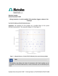
Figure 15 – Overview of the connections for modulated illumination experiments (FRA32M)
The light intensity of the LED array is controlled by setting the driving current
(passing through the LED power plug on the right-hand side). This driving current
is defined by setting the DAC164 #1 output to a value between 0 and 10 V and by
setting the amplitude of the FRA V output to a value between 0 and 0.35 V (RMS).
The difference between the DAC164 output and the FRA V output is converted by
the LED driver to a modulated current using the following relationship:
𝑖𝐿𝐸𝐷 = 𝑖𝐷𝐶 − 𝑖𝐴𝐶 = �
𝑖𝑅𝑎𝑛𝑔𝑒
(𝑉
− 𝑉𝐹𝑅𝐴 𝑉 )�
𝑉𝑅𝑎𝑛𝑔𝑒 𝐷𝐴𝐶164
𝑖𝐿𝐸𝐷 = 100 𝑚𝐴/𝑉 ∙ (𝑉𝐷𝐴𝐶164 − 𝑉𝐹𝑅𝐴 𝑉 )
Where 𝑖𝐿𝐸𝐷 is the output driving current, in mA, 𝑖𝑅𝑎𝑛𝑔𝑒 is the current range of the
LED driver (1000 mA by default), 𝑉𝑅𝑎𝑛𝑔𝑒 is the input range of the LED driver (10 V),
𝑉𝐷𝐴𝐶164 is the output value of the DAC164 #1, in V and 𝑉𝐹𝑅𝐴 𝑉 is the output value
of the FRA V, in V.
Warning
The 𝑉𝐷𝐴𝐶164 value must always be larger than 𝑉𝐹𝑅𝐴 𝑉 so that the 𝑉𝐷𝐴𝐶164 −
𝑉𝐹𝑅𝐴 𝑉 difference is always positive. When this difference is negative, the net
output driving current 𝑖𝐿𝐸𝐷 is 0 mA, regardless of the values of 𝑉𝐷𝐴𝐶164 and
𝑉𝐹𝑅𝐴 𝑉 .
21 | P a g e