1
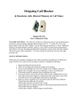
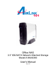
Instruction Manual for A5000 Series of Unit Meters
8.1.15 Frequency Measuring Unit (open collector, logic, and magnet)
Range Measurement
range
11
0.1 to 200Hz
12
1 to 2000Hz
13
0.01 to 20kHz
14
0.1 to 200kHz
Indication
Prescale : 0.001 to 5
Frequency division : 1 to 100
Input type
Input voltage level
Open collector LO : 1 V or less (5 V: 2.2 kΩ pull up)
Logic
LO : 1 V or less, HI: 2.5 to 15 V
Magnet
0.3 to 30Vp-p
Highest
resolution
0.1Hz
1Hz
10Hz
100Hz
Input
impedance
1∼10s
1s
100ms
100ms
Accuracy
±(0.2% of FS)
Maximum permissible input
30V
15V
15V
Duty ratio: 50%
8/8
Instruction Manual for A5000 Series of Unit Meters
8.3.3 Communicating Function
A5000 Series of Unit Meters
(UU-33330)
RS-232C
RS-485
Synchronization system
Start and stop synchronization
Communication system
Full duplex Two-wire half duplex (polling selecting system)
Communication rate
36400bps/19200bps/9600bps/4800bps/2400bps
1bit
Start bit
7 bits/8 bits
Data length
Error detection
Even parity/odd parity/non-parity
BCC (block check character) check sum
1 bit/2 bits
Stop bit
ASCII code
Character code
No procedure
Communication control procedure
Signal name used
TXD,RXD,SG
Non-inversion (+) and inversion (-)
Number of connectable units
1
1 Up to 31 meters
Line length
15m
Up to 500 m (total)
Delimiter
CR+LF/CR
1/8
2. Mounting the Product
2.1 Dimensions for Cutting Panel
Cut the panel for mounting according to the following dimensions.
92 +0.8
-0
+0.6
45 -0
8.1.16 Frequency Measuring Unit (500 Vrms)
8.4 External Dimensions
Range Measurement
range
11
12
13
14
0.1 to 200Hz
1 to 2000Hz
0.01 to 20kHz
0.1 to 200kHz
Indication
Prescale: 0.001 to 5
Frequency division: 1 to 100
Highest
resolution
Indication updatingtime interval
0.1Hz
1Hz
10Hz
100Hz
1 to 10s
1s
100ms
100ms
Accuracy
70 mm
min.
±(0.2% of FS)
! Caution
Input type Input voltage level Max imum permissible input
Voltage 50 to 500Vrms
500V
(1)
Duty ratio : 50%
(2)
8.1.17 Strain Gage Unit
(3)
Sensor power Zero adjusting range Span adjusting range Highest resolution
Accuracy
5V
0.5µV/digit
-0.3 to +2mV/V
1 to 3mV/V
±(0.1% of FS + 2digit)
10V
1µV/digit
Input circuit : Single ended type
Applicable sensor : 350Ω
Sensor power:5 V ± 5% (within 15 mA)or 10 V ± 5%
Operating system :∆Σ conversion
(within 30 mA)
Maximum sampling rate : 12.5 times per second
(4)
(5)
8.1.18 Process Signal Measuring Unit
Range
1V
2A
Measurement
range
1 to 5V
4 to 20mA
120 mm min.
2.2 Mounting the Product to the Panel
To mount the A5000 to the panel, remove its fittings and insert it through the hole
in the front of the panel. From the back of the panel, fix the product to the panel
with the fittings.
1. Before Using the Product
Indication
Input
impedance
Offset : ±9999
About 1 M Ω
Full scale : 0 to ±9999 About 10 Ω
Input circuit : Single ended type
Operating system :∆Σ conversion
Do not apply a voltage or current exceeding the maximum allowable
value; otherwise, it may damage the equipment.
Use a power voltage within the operation range; otherwise, it may result in
a fire, electrical shock, or malfunction.
The contents of this manual are subject to change without notice.
Although the contents of this manual have been prepared with extra care,
if you have any questions, or find errors or missing information, contact
the sales agent from which you purchased the product or Asahi Keiki Co.,
Ltd.
After reading this manual thoroughly, keep it in a convenient place for
future reference.
Maximum
permissible input
±100V
±100mA
Thank you for purchasing the A5000 series. This manual should be passed on to
the person who operates the product. Examine the product for damage caused by
transportation or any other defects. If you find any damage or defects, contact the
sales agent from which you purchased the product or Asahi Keiki Co., Ltd.
Accuracy
±(0.2% of FS)
Maximum sampling rate : 12.5 times per second
Noise rejection ratio : NMR 50 dB or more (50 Hz or 60 Hz)
1.1 Model Codes
8.2 Common Specifications
The model lineup of the A5000 series is shown below. Check that the model code
and specifications of your product match those you specified when ordering.
Display : 7-segment LED display (character height : 14.2 mm on main display and 8 mm on sub-display)
Polarity indication : Automatically indicated when the calculated result is negative.
Indication range : -9999 to 9999
Over-range alarm : OL or -OL for input signals outside the indication range
A 5XXX - XX
Decimal point : Can be set at an arbitrary digit.
Zero indication : Leading zero suppression
Input unit
01: DC voltage measuring unit
(range 11: ±99.99 mV)
External control : HOLD, PH, DZ (reset for frequency measuring unit)
Operating temperature and humidity range : 0 to 50°C, 35 to 83% RH (non-condensing)
Storage temperature and humidity range : -10 to 70°C, 60% RH or less
Power supply : 100 to 240 V AC ±10% for AC power supply unit
9 to 50 V DC for DC power supply unit
Power consumption : Approx. 5 W
External dimensions : 96 mm (W) x 48 mm (H) x 146.5 mm (D)
Note: Depth (D) denotes the maximum value.
Weight : Approx. 450 g
Withstand voltage : 2000 V AC for 1 min. between power terminals and input terminal, and between power terminals and
each output terminal (AC power supply)
Withstand voltage : 500 V DC for 1 min. between power terminals and input terminal, and between power terminals and each
output terminal (DC power supply)
Withstand voltage : 500 V DC for 1 min. between input terminal and each output terminal, and between analog output
terminal and communication terminals
2000 V AC for 1 min. between case and each terminal (common to both AC and DC supply)
Insulation resistance : 100 M Ω between the above terminals when 500 V DC is applied
8.3 Output Specifications
8.3.1 Output for Comparison
Conditions for comparison
Judgment result
Indicated value > Upper limit judgment value
HI
Low er limit judgment value ≤ Indicated value ≤ Upper limit judgment value
Low er limit judgment value > Indicated value
GO
LO
9. Warranty and After-service
9.1 Warranty
The warranty period shall be one year from the date of delivery. Any failure that
arises during this period and the cause thereof is judged to be obviously attributable to Asahi Keiki Co., Ltd. shall be remedied at no cost.
9.2 After-service
This product is manufactured, tested, inspected, and then shipped under
stringent quality control. Should the product fail, however, contact (or send the
product to) your vendor or Asahi Keiki directly. (It is advisable that you send a
memo describing the failure in as much detail as possible along with the
product returned.)
For details on the handling of A5000 meters, either purchase the optional "A5000
User's Manual" or download it from Asahi Keiki's Web site.
Control system : Micro computer operating system
Judgment value setup range : -9999 to 9999
Hysteresis : Can be set in the range of 1 to 999 digits for each judgment value
Operating speed : Depends on the sampling rate.
ASAHI KEIKI CO.,LTD.
Output method : Relay contact output (Make and break contacts for HI and LO and make contacts for GO)
Output rating :240 V AC, 8 A (resistive load) and 30 V DC, 8 A (resistive load)
TOKYO HEAD OFFICE
8.3.2 Analog Output
Output type Load resistance
Accuracy
Ripple
0 to 1V
10 k Ω or more
±50mVpp
0 to 10V
10 k Ω or more
±(0.5% of FS )
1 to 5V
10 k Ω or more
4 to 20mA
550 Ω or less
±25mVpp
Conversion system: PWM conversion
Resolution: Equivalent to 13 bits
Scaling: Digital scaling
Response speed: About 0.5 second
! Caution
33-6, YAGUCHI 2-CHOME, OHTA-KU,
TOKYO, 146-8505, JAPAN
FAX:
(813)-3757-2989
PHONE: (813)-3579-3893
OSAKA OFFICE
20-13, CHOEIJI, HIGASHI-OSAKA-SHI,
OSAKA, 577-0055, JAPAN
FAX:
(816)-6783-6149
PHONE: (816)-6783-7292
NAGOYA OFFICE
29-1, KAMI-YASHIRO 4-CHOME, MEITO-KU,
NAGOYA-SHI, AICHI PREF, 465-0025, JAPAN
FAX:
(8152)-701-9700
PHONE: (8152)-701-9671
http://www.asahikeiki.co.jp
Note: The ripple ratings for the 4-20 mA output
are when the load resistance of 250 Ω and the
output current of 20 mA are applied.
Homepage
(1)
02: DC voltage measuring unit
(range 12: ±999.9 mV; range 13: ±9.999 mV)
(range 14: ±99.99 mV; range 15: ±9.999 mV)
03: DC current measuring unit
(range 23: ±9.999 mA; range 24: ±99.99 mA; range 25: ±999.9 mA)
04: AC voltage measuring unit (average rms)
(range 11: 99.99 mV; range 12: 999.9 mV; range 13: 9.999 V)
05: AC voltage measuring unit (average rms)
(range 14: 99.99 V; range 15: 600 V)
06: AC voltage measuring unit (true rms)
(range 11: 99.99 mV; range 12: 999.9 mV; range 13: 9.999 V)
07: AC voltage measuring unit (true rms)
(range 14: 99.99 V; range 15: 600 V)
08: AC current measuring unit (average rms)
(range 23: 9.999 mA; range 24: 99.99 mA; range 25: 999.9 mA)
09: AC current measuring unit (average rms)
(range 26: 5 A)
10: AC current measuring unit (true rms)
(range 23: 9.999 mA; range 24: 99.99 mA; range 25: 999.9 mA)
(2)
(3)
Mount the product to a panel that is strong enough to hold the product. If the
panel is not strong enough or the product is not fixed tightly, it may fall down and
cause injury.
The A5000 does not have a power switch, and will thus be immediately ready for
operation upon connecting it to a power supply.
If the product is installed inside other equipment, provide sufficient heat
dissipation to ensure that the temperature inside the equipment does not exceed
50°C.
3. Terminal Arrangement
Comparison
output
Serial
communication
12 13 14 15 16 17 18 19
11: AC current measuring unit (true rms)
(range 26: 5 A)
12: Resistance measuring unit
13: Temperature measuring unit (TC)
14: Temperature measuring unit (RTD)
15: Frequency measuring unit
(inputs: open collector, logic, and magnet)
16: Frequency measuring unit
(input: 50 to 500 Vrms)
17: Strain gauze input unit (load cell)
18: Process signal measuring unit (4 to 20 mA or 1 to 5 V)
Display unit
1: Single display
2: Multi display
Power unit
1: 100 to 240 V AC ±10%
2: 9 to 60 V DC
Output unit
0: None
1: Comparison
2: Analog
3: RS-232C
4: RS-485
5: Comparison and analog
6: Comparison, analog, and RS232C
7: Comparison, analog, and RS-485
Analog output
20 22
24 25 26
21 23
6
Input (the shape depends on the unit.)
Asahi Keiki Co., Ltd
7
8
9
External
control
10 11
Power
connector
UU-33330
2002.04
Instruction Manual for A5000 Series of Unit Meters
3.3.9 Temperature Measuring Unit (TC)
3.1 Power
Terminal No.
10
2/8
11
Name
Description
10
POWER P ower terminal without polarity for both DC and AC
11
POWER P ower terminal without polarity for both DC and AC
1
3.2 External Controls
6
7
8
Nam e
1
2
3
+
NC
-
Name
6
HOLD
Description
Positive terminal for thermocouple
Do not connect this terminal.
Negative terminal for thermocouple
3
7
Description
Control for hold function. Enabled when short-circuited or at
the same potential as COM.
Control for digital zero function. Enabled when shortcircuited or at the same potential as COM.
Control for peak hold function. Enabled when shortcircuited or at the same potential as COM.
Common for all external control terminals.
DZ
8
PH
9
COM
1
2
Terminal No.
Name
1
2
3
A
B
C
3
Description
Resistance sensor wire
Resistance sensor wire
Elimination of wire resistance
Connection of three-wire sensor
3.3 Input Signals
3.3.1 DC Voltage Measuring Unit (Range 11)
1
2
Terminal
No.
Name
1
2
3
HI
NC
LO
3.3.11 Frequency Measuring Unit (Open collector, logic, and magnet)
Description
Positive input terminal
Do not connect this terminal.
Negative input terminal
2
3
4
5
Terminal
No.
Name
1
2
3
4
5
12
13
14
15
LO
1
2
3
4
5
Te r m i n al
No .
Name
1
2
3
4
5
23
24
25
LO
LO
Terminal
No.
2
3
2
3
4
HI
LO
+15 V
0V
COM
5
Positive input terminal for range 12 (±999.9 mV)
Positive input terminal for range 13 (±9.999 V)
Positive input terminal for range 14 (±99.99 V)
Positive input terminal for range 15 (±600 V)
Negative input terminal
1
2
1
11-12
2
3
13
LO
Terminal
No.
Name
1
2
3
HI
NC
LO
Description
Input terminal
Do not connect this terminal.
Input terminal
3
Description
Positive input terminal for range 23 (±9.999 mA)
Positive input terminal for range 24 (±99.99 mA)
Positive input terminal for range 25 (±999.9 mA)
Negative input terminal
Negative input terminal
Name
Positive input terminal
Negative input terminal
Power output for sensor (positive)
Power output for sensor (negative)
Common terminal (grounding terminal for input circuit)
1
2
3
4
Terminal
No .
Nam e
1
2
3
4
5
+SIG
-SIG
+EXC
-EXC
COM
5
Description
Description
Positive input terminal
Negative input terminal
Power output for sensor (positive)
Power output for sensor (negative)
Common terminal (grounding terminal for input circuit)
1
3.3.5 AC Voltage Measuring Unit (Ranges 14 and 15)
2
Terminal
No.
Name
1
2
3
V-IN
A-IN
LO
Description
Positive input terminal for 1 to 5 V range
Positive input terminal for 4 to 20 mA range
Negative input terminal
3
1
2
Name
1
2
3
14
15
LO
Description
Positive input terminal for range 14 (99.99 V)
Positive input terminal for range 15 (600 V)
Common input terminal
3
12 13 14 15
Terminal
No.
Name
12
13
14
15
16
17
18
19
LO-b
LO-c
LO-a
GO-c
GO-a
HI-b
HI-c
HI-a
16 17 18 19
3.3.6 AC Current Measuring Unit (Ranges 23 to 25)
1
2
3
4
5
Terminal
No.
Name
1
2
3
4
5
23
24
25
LO
LO
Description
Positive input terminal for range 23 (±9.999 mA)
Positive input terminal for range 24 (±99.99 mA)
Positive input terminal for range 25 (±999.9 mA)
Negative input terminal
Negative input terminal
24
25
26
1
2
HI
LO
5.8 mm
min.
!
1
2
3
4
5
Name
1
2
HI
LO
3
+S
4
-S
5
COM
COM Common terminal for analog output
A-OUT Current output terminal (4 to 20 mA)
V-OUT Voltage output terminal (1 to 5 V, 0 to 1 V, and 0 to 10 V)
Description
Input terminal for all ranges
Input terminal for all ranges
Constant current for four-wire resistance measurement
(positive)
Constant current for four-wire resistance measurement
(negative)
Common terminal (grounding terminal for input circuit)
The A5000 series can be equipped with an RS-485 interface (when the meter is
provided with an RS-485 unit). For details on the RS-485 function, see the separate manual on communication functions.
7.4 RS-232C Interface Function
The A5000 series can be equipped with an RS-232C interface (when the meter is
provided with an RS-232C unit). For details on the RS-232C function, see the
separate manual on communication functions.
8. Specifications and External Dimensions
Terminal
No .
Name
20
21
22
23
RXD(+)
TXD(-)
NC
SG
Indication
Description
RS-232C: transmission; RS-485: Non-reverse output
RS-232C: reception; RS-485: Reverse output
Do not connect this terminal.
Common terminal for communications
Caution
(1) Use 12 to 28 AWG wire for the power, input (except for range 26), external control, and
comparison output connectors.
(2) Tighten the screws for the power, input (except for range 26), external control, and comparison
output connectors to a torque of 0.5 to 0.6 Nm.
(3) Use 16 to 28 AWG wire for the analog output connector.
(4) Tighten the screws of analog output connector to a torque of 0.22 to 0.25 Nm.
Highest
Input
resolution
impedance
10mV
1 MΩ or more
100mV
1 MΩ or more
Offset: ±9999
Full scale: 0 to ±9999
Maximum
permissible input
250V
600V
Accuracy
±(0.2% of rdg + 20digit)
±(0.3% of rdg + 20digit)
Input circuit : Single ended type
Response speed : About 1 secon
Operating system:∆Σ conversion
Crest factor : 4:1 at full scale
Maximum sampling rate : 12.5 times per second Dead zone : 0 to 99 digits
Frequency range : 40 Hz to 1 kHz
8.1.7 AC Voltage Measuring Unit (true rms value: ranges 14 and 15)
23
24
25
Measurement
range
9.999mA
99.99mA
999.9mA
Indication
Highest
resolution
1µA
10µA
100µA
Offset: ±9999
Full scale : 0 to ±9999
Input circuit : Single ended type
Operating system :∆Σ conversion
Maximum sampling rate : 12.5 times per second
Input
impedance
A bout 10 Ω
About 1 Ω
About 0.1 Ω
Maximum
permissible input
100mA
500mA
3A
Accuracy
±(0.5% of rdg + 10digit)
Frequency range : 40 Hz to 1 kHz
Response speed : About 1 second
Dead zone : 0 to 99 digits
8.1.8 AC Current Measuring Unit (average value detection: ranges 23 to 25)
Range Measurement
range
26
7.3 RS-485 Interface Function
Indication
Highest
resolution
Input
impedance
Maximum
permissible input
Accuracy
1mA
(CT)
8A
±(0.5% of rdg + 10digit)
Offset: ±9999
Full scale : 0 to ±9999
5A
Input circuit : CT isolation type
Frequency range : 50 Hz or 60 Hz
Operating system :∆Σ conversion
Response speed : About 1 second
Maximum sampling rate : 12.5 times per second Dead zone : 0 to 99 digits
8.1.9 AC Current Measuring Unit (average value detection: range 26)
Range Measurement
range
23
9.999mA
24
99.99mA
25
999.9mA
Indication
Offset: ±9999
Full scale : 0 to ±9999
Highest
resolution
1µA
10µA
100µA
Input
impedance
About 10 Ω
About 1 Ω
About 0.1 Ω
Maximum
permissible input
100mA
500mA
3A
Accuracy
±(0.5% of rdg + 20digit)
Input circuit : Single ended type
Response speed : About 1 second
Operating system :∆Σ conversion
Crest factor : 4:1 at full scale
Maximum sampling rate : 12.5 times per second Dead zone : 0 to 99 digits
Frequency range : 40 Hz to 1 kHz
8.1 Input Specifications
8.1.10 AC Current Measuring Unit (true rms value: ranges 23 to 25)
8.1.1 DC Voltage Measuring Unit (range 11)
11
±99.99mV
Indication
Offset : ±9999
Full scale : 0 to ±9999
Input circuit : Single ended type
Operating system :∆Σ conversion
Highest
resolution
Input
impedance
Maximum
permissible input
Accuracy
10µV
About 100 MΩ
±100V
±(0.1% of FS)
Maximum sampling rate : 12.5 times per second
Noise rejection ratio :
NMR (normal mode rejection) 50 dB or more (50 or 60 Hz)
Range Measurement
range
12
±999.9mV
13
±9.999V
14
±9.999V
15
±600V
Indication
Highest
Input
Maximum
resolution
impedance permissible input
100µV
About 100 Ω
±100V
1mV
About 1 MΩ
±250V
10mV
About 10 M Ω
±250V
100mV About 10 M Ω
±600V
Offset: ±9999
Full scale : 0 to ±9999
Input circuit: Single ended type
Operating system :∆Σ conversion
Accuracy
±(0.1% of FS)
±(0.15% of FS)
Maximum sampling rate : 12.5 times per second
Noise rejection ratio: NMR 50 dB or more (50 or 60 Hz)
Offset: ±9999
Full scale : 0 to ±9999
Input circuit : Single ended type
Operating system :∆Σ conversion
Highest
resolution
1µA
10µA
11µA
Input
impedanc e
About 10 Ω
About 1 Ω
Αβουτ 0.1 Ω
Maximum
permissible input
±100mA
±500mA
±3A
Accurac y
Indication
Offset: ±9999
Full scale : 0 to ±9999
±(0.3% of FS)
Maximum sampling rate : 12.5 times per second
Noise rejection ratio : NMR 50 dB or more (50 or 60 Hz)
Highest
resolution
10µV
100µV
1mV
Input
Maximum
Accuracy
impedance permissible input
1 MΩ or more
100V
±(0.2% of rdg + 10digit)
1 MΩ or more
100V
250V
1 ΜΩ ορ µορε
Frequency range : 40 Hz to 1 kHz
Response speed : About 1 second
Dead zone : 0 to 99 digits
8.1.5 AC Voltage Measuring Unit (average value detection: ranges 14 and
15)
Range Measurement
range
14
99.99V
15
600V
Indication
Offset: ±9999
Full scale : 0 to ±9999
Highest
Input
Maximum
resolution
impedance permissible input
10mV
1 MΩ or more
250V
100mV
600V
1 ΜΩ or more
Accuracy
±(0.2% of rdg + 10digit)
±(0.3% of rdg + 10digit)
Indication
Offset: ±9999
Full scale : 0 to ±9999
Highest
resolution
10µV
100µV
1mV
Input
impedance
1 MΩ or more
1 MΩ or more
1 MΩ or more
Maximum
permissible input
100V
100V
250V
Input circuit:Single ended type
Response speed : About 1 second
Operating system :∆Σ conversion
Crest factor : 4:1 at full scale
Maximum sampling rate : 12.5 times per second Dead zone : 0 to 99 digits
Frequency range : 40 Hz to 1 kHz
5A
Range
11
12
13
14
1mA
(CT)
Maximum
permissible input
Accuracy
8A
±(0.5% of rdg + 20digit)
About 1 second
1 at full scale
0 to 99 digits
Measurement
range
99.99Ω
999.9Ω
9.999kΩ
99.99k
Indication
Offset: ±9999
Full scale : 0 to ±9999
Highest
Maximum
resolution permissible input
10mΩ
About 5 mA
0.1Ω
About 0.5 mA
1Ω
About 50 µA
10Ω
About 5 µA
Accuracy
±(0.2% of FS)
8.1.12 Resistance Measuring Unit
Range
Accuracy
±(0.2% of rdg + 20digit)
Input
sensor
KA
K
KB
K
J
J
T
T
S
S
R
R
B
B
Indication
-50.0 to 199.9°C
(-58.0 to 391.8°F)
-50 to 1200°C
(-58 to 2192°F)
-50 to 1000°C
(-58 to 1832°F)
-50 to 400°C
(-58 to 752°F)
0 to 1700°C
(32 to 3092°F)
-10 to 1700°C
(14 to 3092°F)
100 to 1800°C
(212 to 3272°F)
Highest
resolution
0.1°C
(0.1°F)
Accuracy
±(0.5% of FS)
±(0.2% of FS)
1°C
(1°F)
±(0.6% of FS)
±(0.4% of FS)
Note : The accuracy of range B
is applicable to temperatures of
500°C or more.
Input circuit : Single ended type
Internal resistance of sensor : 50 Ω or less
Operating system :∆Σ conversion
Linearizer : Digital linearizer
Maximum sampling rate : 12.5 times per second Burnout alarm : N/A
Cold junction compensation error : ±1°C(at 10 through 40°C )
8.1.13 Temperature Measuring Unit (TC)
Range
Frequency range: 40 Hz to 1 kHz
Response speed : About 1 second
Dead zone : 0 to 99 digits
8.1.6 AC Voltage Measuring Unit (true rms value: ranges 11 to 13)
Range Measurement
range
11
99.99mV
12
999.9mV
13
9.999V
Input
impedance
Input circuit : CT isolation type
Response speed:
Operating system : DS conversion
Crest factor: 4:
Maximum sampling rate : 12.5 times per second Dead zone:
Frequency range:
50 Hz or 60 Hz
±(0.2% of FS)
8.1.4 AC Voltage Measuring Unit (average value detection: ranges 11 to 13)
Range Measurement
range
11
99.99mV
12
999.9mV
13
9.999V
Highest
resolution
Input circuit : Single ended type
Measuring system : Two-wire system or four-wire system
(internal socket change-over)
Operating system :∆Σ conversion
Maximum sampling rate : 12.5 times per second Open-circuit voltage : About 5 V
8.1.3 DC Current Measuring Unit
Indication
26
Indication
Offset: ±9999
Full scale : 0 to ±9999
8.1.11 AC Current Measuring Unit (true rms value: range 26)
8.1.2 DC Voltage Measuring Unit (ranges 12 to 15)
Input circuit : Single ended type
Operating system :∆Σ conversion
Maximum sampling rate : 12.5 times per second
20 21 22 23
3.3.8 Resistance Measuring Unit
Terminal No.
Description
3.6 Serial Communication
Input terminal
Input terminal
Applicable solderless terminals
2
LO output terminal (b contact)
Common terminal for LO output
LO output terminal (a contact)
Common terminal for GO output
GO output terminal (a contact)
HI output terminal (b contact)
Common terminal for HI output
HI output terminal (a contact)
Description
5.8 mm
min.
1
Name
Name
Range Measurement
range
14
99.99V
15
600V
Range
The A5000 series of unit meters can output an analog signal for an indicated
value (when the meter is equipped with an analog output unit). There are four
output ranges, 0 to 1 V/0 to 10 V/1 to 5 V/4 to 20 mA, from which a selection can
be made using the condition data. In addition, the analog output of the A5000
series allows for arbitrary output scaling. This scaling can be achieved by setting
the indication value for an output of the maximum scale value (20 mA for 4–20
mA output range) in the AOHI parameter of the scaling data.
Input circuit : Single ended type
Operating system :∆Σ conversion
Maximum sampling rate : 12.5 times per second
Terminal
No.
24 25 26
Terminal
No.
Description
3.5 Analog Output
3.3.7 AC Current Measuring Unit (Range 26)
7.2 Analog Output Function
Range Measurement
range
23
±9.999mA
24
±99.99mA
25
±999.9mA
3.4 Comparison Output
Terminal
No.
The A5000 series of unit meters is designed so that the two judgment values HI
and LO can be set for the measured (indicated) value to provide the results of
judgment as relay contact output. (This function is effective when the meter is
equipped with a comparison output unit.) For details on the contact ratings and
other specifications, refer to the section “Output Specifications.”
Range Measurement
range
3.3.14 Process Signal Measuring Unit
Positive input terminal for ranges 11 (99.99 mV) and
12 (999.9 mV)
Positive input terminal for range 13 (9.999 V)
Common input terminal
7.1 Comparison Output Function
Range Measurement
range
3.3.13 Strain Gauge Input Unit (Load cell)
3.3.4 AC Voltage Measuring Unit (Ranges 11 to 13)
1
1
2
3
4
5
Description
3.3.12 Frequency Measuring Unit (500 Vrms)
Description
3.3.3 DC Current Measuring Unit
1
Name
3
3.3.2 DC Voltage Measuring Unit (Range 12)
1
Terminal
No.
7/8
7. Output Function
3.3.10 Temperature Measuring Unit (RTD)
Terminal No.
9
2
Terminal No.
Instruction Manual for A5000 Series of Unit Meters
PA
JPA
PB
JPB
Input
sensor
PT100 Ω
JPt100 Ω
PT100 Ω
JPt100 Ω
Indication
-100.0 to 199.9°C
(-148.0 to 391.8°F)
-100.0 to 600°C
(-148.0 to 391.8°F)
Highest
Accuracy
resolution
0.1°C
±(0.15% of FS)
(0.1°F)
1°C
±(0.3% of FS)
(1°F)
Input circui t: Single ended type
External resistance : 10Ω or less per wire
Operating system :∆Σ conversion
Linearizer : Digital linearizer
Maximum sampling rate :12.5 times per second Burnout alarm : N/A
Current through RTD : About 1 mA
8.1.14 Temperature Measuring Unit (RTD)
Instruction Manual for A5000 Series of Unit Meters
5.4.4 Method of Setting Calibration Data
5.4.4.1 Actual Load Calibration
Actual load calibration means that calibration is carried out by applying actually
measured pressure to a sensor such as a load cell connected to the meter.
6/8
5.4.5 Method of Setting Linearization Data
The linearization function means a function that changes the slope of straight lines in the
relationship between the input and indication by correcting the relations at arbitrary points.
Linearization data are set using the input value (indicated value before correction) and the
output value (indicated value after correction) at each arbitrary point.
Instruction Manual for A5000 Series of Unit Meters
4.
Components and their Functions
5.
The front panel design of the A5000 series of unit meters differs depending on the
display unit selected. The names and functions of each unit are as shown below.
Multi-display unit
Single display unit
Parameter Setup
5.1 Differences between Display Units
5.1.1 Multi-display Unit
4.1 Multi-display Unit
(4)
(2)
Multi-display unit
3/8
Single display unit
(1)
(5)
(3)
(1) Press the Mode key and the Enter key during
measurement.
(1) Press the Shift, Increment, and Enter keys
together during measurement.
(6)
No.
(2) Press the Shift key a few times to move to the
linearization data menu.
(2) Press the Mode key to change to the actual
load calibration mode.
(1)
(3) Press the Mode key to move to the setup for the
number of data to be corrected.
(3) Press the Mode key while applying pressure
that will cause the display to show zero.
(4) Press the Shift key (change digit) and the
Increment key (change numeric value) and then press
the Mode Key to after the number of data to be
corrected has been set.
&
(4) For a single display unit, press the Mode key
to change to the parameter information indication.
Note: The decimal point in the selected digit
flashes.
(5) For a single display unit, press the Mode key to
change to the parameter information indication.
&
or
(5) Press the Shift key (change digit) and
Increment key (change numeric value) to set
8000.
Note:The decimal point in the selected digit
flashes.
RE
(6) Press the Enter or Mode key to return to the
measurement mode.
DZ
&
Note: For a single display unit, RE flashes when
the input value is set and DZ flashes when the
output value is set.
(7) Press the Shift key (change digit) and Increment
key (change numeric value) and then press the Mode
key after the N-01 output value has been set.
(8) Press the Mode key to display the setup for output
values of the data to be corrected.
RE
Multi-display unit
Single display unit
&
(4) Sub-display 1
(5) Sub-display 2
(6) Enter key
(7) Mode key
(8) Shift key
(9) Increment key
Repeat steps (5) to (9) until all the settings have
been made.
(1) Press the Shift, Increment, and Enter key together
during measurement.
(10) When all the settings have been made, press the
Enter key to return to the measurement mode.
(2) Press the Increment key to select the equivalent
calibration mode.
(4) Press the Shift key to display the zero-input setup
mode.
Note:For a single display unit, the unit
automatically returns to ZERO indication if there is
no key operation for about 8 seconds. In such a
case, press the Mode key to return to the numerical
value indication.
&
(5) Press the Shift key (change digit) and the
Increment key (change numeric value) to set 0.004.
Note:The decimal point in the selected digit flashes.
(6) Press the Mode key to change to the span input
value setup mode.
(7) For a single display unit, press the mode key to
display the parameter information indication.
&
(8) Press the Shift key (change digit) and the
Increment key (change numeric value) to set 1.002.
(9) Press the Mode key to change to the span
indicating value setup mode.
(10) For a single display unit, press the Mode key to
display the parameter information indication.
&
(11) Press the Shift key (change digit) and the
Increment key (change numeric value) to set 2000.
Note:The decimal point in the selected digit flashes.
or
(12) Press the Enter or Mode key to return to the
measurement mode.
Note:
6.
Returns to the measurement mode.
Selects the item to be set.
Parameter name
Note: Pressing the Mode key displays the next parameter.
5.1.2 Single Display Unit
Setup contents and parameter name
Note 1: Pressing the mode key with the parameter name shown changes the display to the parameter information indication. If there is no key operation for about one second when the parameter name is shown, the display automatically changes to the parameter information indication (however, this change does not automatically occur for parameters PH/S-HI/
FSC, etc., right after COND/COM/MET is indicated).
Changes the digit to be set.
Changes the value or content of a
selected digit. (Increments the value)
Note 2: Pressing the Mode key when the parameter information indication is
shown results in the next parameter being displayed.
Note 3: If there is no key operation for about 8 seconds with the parameter information indication shown, the display returns to the parameter name indication.
5.2 Moving to the Parameter Setup Mode
Resets the maximum/minimum/(maximum-minimum)/input value
monitoring mode. (Hold down the key for about one second.)
Calibration data
Measurement
4.2 Single Display Unit
(2)
(3) Press the Mode key to move to the equivalent
calibration mode.
Setup contents
During parameter setup
IIndicates information on the parameter
to be set.
Pressing the Enter and Mode keys together changes to the
parameter setting mode.
Pressing the Enter and Increment keys together changes to the
maximum/minimum/(maximum-minimum)/input value monitoring
mode.
Switches from the maximum/minimum/(maximumminimum)/input value monitoring mode to the comparative
judgment reading mode.
Pressing the Mode and Enter keys together changes to the
parameter setting mode.
Pressing the Mode and Shift keys together changes to the shift
function setup mode.
Pressing the Mode and Incremental keys together turns on/off
the “Digital zero” indicator.
Pressing the Shift and Enter keys together changes to the
parameter checking mode. (Comparator data can be set.)
Pressing the Shift and Mode keys together changes to the shift
function setup mode.
Selects from items in the maximum/minimum/(maximumminimum)/input value monitoring mode. (Hold down the key for
about one second.)
Pressing the Increment and Mode keys together turns on/off the
“Digital zero” indicator.
Pressing the Increment and Enter keys changes to the
maximum/minimum/(maximum-minimum)/input value monitoring
mode.
Note: For a single display unit, the unit is
automatically returned to N-02 indication if there is
no key operation for about 8 seconds. In this case,
press the Mode key to return to the numeric value
indication.
(9) Press the Shift key (change digit) and Increment
key (change numeric value) and then press the Mode
key after the N-02 input value has been set.
(9)
HI Indicates the result of judgment and turns on if the measured
value > HI judgment value.
GO Indicates the result of judgment and turns on if LO judgment
value ≤ the measured value ≤ HI judgment value.
LO Indicates the result of judgment and turns on if the measured
value < LO judgment value.
ME Turns on if “digital zero backup” is on.
PH Turns on if “peak hold/valley hold/peak - valley hold” is on.
DZ Turns on if “digital zero” is on.
RE Turns on if remote control is being performed through RS-232C
or RS-485 interface.
Indicates the HI side judgment value.
Indicates the item in the maximum/minimum/(maximumminimum)/input value monitoring mode.
Indicates the LO side judgment value.
Indicates the item to be set.
Indicates information on the item in the
maximum/minimum/(maximum-minimum)/input value monitoring
mode.
(6) Press the Shift key (change digit) and Increment
key (change numeric value) and then press the Mode
key after the N-01 input value has been set.
&
5.4.4.2 Equivalent Calibration
Equivalent calibration means that calibration is carried out according to the ratings (specifications) of such a sensor as a load cell. It is not necessary to connect
the sensor or to apply pressure to the sensor.
Note: For a single display unit, the unit
automatically returns to N-01 indication if there is
no key operation for about 8 seconds. In this case,
press the Mode key to return to the numeric value
indication.
(3) Function
indicators
(8)
During measurement
Indicates the measured value.
Main display
(2) Judgment
indicators
(7)
Main Functions
Name
(1)
(3)
(1)
(3)
The setup conditions are N-1 < N-2 … N-15 < N-16.
Control Functions
6.1 Hold Function
The Hold function temporarily retains the indication. The hold function is enabled by
shortcircuiting the HOLD and COM terminals or setting both terminals to the same
voltage level. As a result the display unit retains the indication given at that moment.
(6)
No.
(2) Judgment
indicators
PH
DZ
ME
RE
(7) Mode key
(8) Shift key
6.3 Peak Hold Function
The Peak Hold function retains one of the maximum (peak hold)/minimum (valley
hold)/maximum - minimum (peak-valley hold) values and provides output for that
value. Selection from these values is made using the condition data. The peak hold
function is enabled by shortcircuiting the PH and COM terminals or setting both
terminals to the same voltage level.
HI
LO
(6) Enter key
(9) Increment key
(9)
(6)
(7)
(8)
(9)
During measurement
Indicates the measured value.
GO
(3) Function
indicators
(8)
Main functions
Name
(1) Main display
6.2 Digital Zero Function
The Digital Zero function zeros the indication given at an arbitrary timing. Thereafter, the function shows the amount of change from the point of zeroing. However, this function serves as an indication resetting function for a frequency measuring unit. Thus, the Digital Zero function can be used to reset the indication
when there is no input signal at all.
Note that, the on/off control of the Digital Zero function can be achieved by means
of terminal control or front panel keys. In the case of terminal control, the Digital
Zero function is turned on by shortcircuiting the DZ and COM terminals or setting
both terminals to the same voltage level. The indication at that moment is zeroed.
In the case of control with the front panel keys, hold down the Mode key and press
the Increment key for about 1 second to zero the indication at that moment.
Note: Operation with the control terminals takes priority over operation
with the front panel keys. The Digital Zero function is disabled if the
control terminals are made to go through the off-on-off sequence with
the function enabled by means of the front panel keys.
(7)
Indicates information on the item in the
maximum/minimum/(maximum-minimum)/input value monitoring
mode.
Indicates the result of judgment and turns on if the measured
value > HI judgment value.
Indicates the result of judgment and turns on if LO judgment
value ≤ the measured value ≤ HI judgment value.
Indicates the result of judgment and turns on if the measured
value < LO judgment value.
Turns on if “peak hold/valley hold/peak - valley hold” is on.
Turns on if “digital zero” is on.
Flashes when linearization data output values are set.
Turns on if “peak hold/valley hold/peak - valley hold” is on.
Turns on if remote control is being performed through RS-232C
or RS-485 interface.
Flashes when linearization data input values are set.
Pressing the Mode and Enter keys together changes to the
parameter setting mode.
Pressing the Increment and Enter keys together changes to the
maximum/minimum/(maximum-minimum)/input value monitoring
mode.
Switches from the maximum/minimum/(maximumminimum)/input value monitoring mode to the comparative
judgment reading mode.
Pressing the Mode and Enter keys together changes to the
parameter setting mode.
Pressing the Shift and Mode keys together changes to the shift
function setup mode.
Pressing the Increment and Mode keys together turns on/off the
“Digital zero” indicator.
Pressing the Shift and Enter keys together changes to the
parameter checking mode. (Comparator data can be set.)
Pressing the Shift and Mode keys together changes to the shift
function setup mode.
Holding down the Shift key for about one second moves to the
HI judgment value indicator.
Selects from items in the maximum/minimum/(maximumminimum)/input value monitoring mode. (Hold down the key for
about one second.)
Pressing the Increment and Mode keys together turns on/off the
“Digital zero” indicator.
Holding down the Increment key for about one second moves to
the LO judgment value indicator.
Pressing the Increment and Enter keys together changes to the
maximum/minimum/(maximum-minimum)/input value monitoring
mode.
Resets the maximum/minimum/(maximum-minimum)/input value
monitoring mode. (Hold down the key for about one second.)
During parameter setup
Indicates information on the parameter
to be set.
Returns to the measurement mode.
Condition data
Comparator data
Scaling data
Linearization data
Selects the item to be set.
Pressing the ENTER key saves the data and returns to the measurement mode.
(Data are backed up with EEPROM even when the power is turned off.)
Changes the digit to be set.
Changes the value or content of a
selected digit. (Increments the value)
Instruction Manual for A5000 Series of Unit Meters
4/8
5.3 Data Lists and Default Settings
Indication
Default Equipped
value
as
Name
Condition data
PVH Peak hold setup
PH
RANG Measurement range setup
AVG
1
MAV
OFF
¡
1
OFF
C
9600
7
E
2
CR.LF
00
OFF
OFF
CLR
OC
00
01
10
OFF
OFF
ON
¡
¡
FSC
Full scale indication value setup
FIN
Full scale input value setup
OFS
Offset indication value setup
OIN
5.4.2 Method of Setting Comparator Data
01
02
03
04
05
06
07
08
r
11
¡
r
15
¡
¡
25
¡
¡
13
¡
¡
15
¡
¡
13
¡
¡
15
¡
¡
25
¡
13
14
15
16
17
18
¡
14
¡
¡
B
¡
¡
JPB
¡
¡
14
r
¡
14
r
r
¡
2A
¡
r
26
¡
¡
25
¡
r
26
¡
¡
*1
*1
*1
Offset input value setup
Name
7
Single display unit
This section explains comparator data and shows a typical example of setting the
HI side judgment value. The same method applies to all other parameters.
¡
¡
¡
¡
¡
HI side judgment value
HI side hysteresis value
LO side judgment value
LO side hysteresis value
:
:
:
:
(1) Press the Mode and Enter keys together
during measurement.
900
200
300
150
(2) Press the Shift key a few times to change to
the scaling data menu.
r
r
r
r
r
r
r
r
r
r
r
r
r
¡
¡
¡
¡
¡
¡
r
r
¡
¡
¡
¡
¡
¡
r
r
r
r
r
r
r
¡
¡
¡
¡
¡
¡
r
¡
¡
¡
¡
¡
¡
¡
¡
HI side judgment value
1000
900
r
r
r
r
r
r
r
r
r
r
r
r
r
r
r
r
r
r
r
r
r
r
r
r
r
r
r
¡
r
r
r
r
r
r
r
r
r
¡
1/2/4/8/10/20/40/80
r
Default
value
r
r
r
r
r
r
r
r
r
r
r
r
r
r
r
r
r
r
r
r
r
r
r
r
¡
¡
¡
¡
r
r
¡
¡
¡
¡
r
r
r
r
r
r
r
r
r
r
r
r
¡
¡
¡
¡
¡
¡
¡
¡
¡
¡
¡
○
GO
HI
1
1(1digit)/2(2digit)/5(5digit)/0(10digit)
OFF/B-3/B-2/B-1/ON
C/F
9600/4800/2400/384(38400)/192(19200)
7(7bit)/8(8bit)
E (even number), O (odd number), N (none)
2(2bit)/1(1bit)
CR.LF(CR+LF)/CR
01 to 99
OFF/0-1(0 to 1V)/0-10(0 to 10V)/1-5(1 to 5V)/4-20(4 to 20mA)
OFF/ON
OFF/ON
OC (open collector)/LGC (logic)/MAG (magnet)
00 to 99
00 to 99
10(10V)/05(5V)
OFF/ON
OFF/1 to 30
OFF/ON
1
OFF
C
9600
7bit
E
2
CRLF
00
OFF
OFF
CLR
O.C
00
01
10
OFF
OFF
ON
-9999 to 9999
-9999 to 9999
-9999 to 9999
-9999 to 9999
1000
500
0
0
-9999 to 9999
-9999 to 9999
-9999 to 9999
-9999 to 9999
0.001 to 5.000
1 to 100
-9999 to 9999
-9999 to 9999
*1
*1
*1
*1
1.000
1
9999
-9999
-9999 to 9999
9999
GO
LO
GO
Multi-display unit
(1) Press the Mode and Enter keys together
during measurement.
(2) Press the Shift key a few times to display the
comparator data menu.
r
r
¡
¡
r
r
r
r
¡
¡
¡
¡
*2
0.000
2.000
9000
For the process signal measuring unit, set the full scale input value to
5.000 for the 1 V range and to 20.00 for the 2 A range, and set the offset
input value to 1.000 for the 1 V range and to 4.00 for the 2 A range.
The following explains the frequency measuring unit. (The same method applies
to the full scale indication parameter.)
¡
¡
(3) Press the Mode key a few times to display the
parameter to be set.
Determining the revolution speed (rpm) using the rotary encoder set to 30 pulses per minute:
(1)Determine the measurement range by calculating the maximum frequency.
r
r
r
r
r
r
r
r
r
r
r
r
r
r
r
r
r
r
r
r
r
r
r
r
r
r
r
r
r
r
¡
¡
¡
r
r
r
(4) For a single display unit, press the Mode key
to change to the parameter information indication.
(The display automatically changes to this
indication in about 1 second, except for parameter
S-HI right after COM is indicated.)
The figure below show s an example w here the revolution rises to a maximum speed of about 100 rpm.
30
r
100
÷
60
=
50
Number of pulses per second
(5) Press the Shift key (change digit) and pres s
the Increment key (change numeric value) to set
to 10.
Note:The decimal point in the selected digit
flashes.
&
( 6 ) P r e s s t h e E n t e r k e y to return to the
measurement mode (Pressing the Mode key
changes to the next parameter).
or
This section shows a typical example of setting the peak hold parameter. The
same method applies to other parameters.
Note:
Multi-display unit
Single display unit
(1) Press the Mode and Enter keys together
during measurement.
The setup conditions are HI side judgment value > LO side judgment
value, HI side judgment value ≥ LO side judgment value + LO side hysteresis, and LO side judgment value ≤ HI side judgment value-HI side
hysteresis. If these conditions are not satisfied, an error indication appears and the display returns to the HI side judgment value setup.
5.4.3 Method of Setting Scaling Data
(2) Press the Mode key to change to the peak
hold setup mode.
Revolution speed per second
Number of pulses per revolution at the rotary encoder
(2)Since the number of pulses determined in (1) is 50 per second (50 Hz), set the range to range 11 .
(for how to set the range, see the section on setting condition data)
(3)The display unit show s 500 if 50 Hz pulse input is measured under range 11 (w hen PS=1 and PPR=1 by
default). Therefore, the parameters should be set as PS=2 and PPR=1 so that the decimal point is positioned
in the 1 01 digit (100.0 is indicated 50 Hz input).
This section explains comparator data and shows a typical example of setting the
Note:
For the frequency measuring unit, set the relationship between the input
and indication using the PS and PPR parameters (parameters of FSC,
FIN, OFS, and OIN are not indicated).
The following explains the scaling of analog output (The same method applies to
the full scale indication parameter.)
full scale indication parameter. The same method applies to all other parameters.
Output
(3) For a single display unit, press the Mode key
to change to the parameter information indication.
(The display automatically changes to this
indication in about 1 second, except right after
COND is indicated.)
(4) Press the Increment key a few times to set to
Valley Hold.
Indication : 0.0 to 500.0
Output
: 4 to 20mA
Indication
AOHI : 5000
AOLO : 0
or
(5) Press the Enter key to return to measurement
mode. (Pressing the Mode key changes to the
next parameter).
20mA
Input voltage : 0 to 10V
Indication
: 0 to 5.000
5000
FSC
F I N
OFS
OIN
DLHI
DLLO
DEP
:
:
:
:
:
:
:
5000
9999
0
0
3000
-2000
The place of 10
3000
4mA
Indication
DLHI
0
Input
0
3
is lit.
-2000
10V
DLLO
Note:
5000
For analog output scaling, set the indication value for an output current
of 20 mA in the AOHI parameter and set the indication value for an
output current of 4 mA in the AOLO parameter (for 4-20 mA output).
0
None
(6) Press the Enter key to return to the
measurement mode (Pressing the Mode key
changes to the next parameter).
Single display unit
Note:
r
r
(5) Press the Shift key (change digit) and press
the Increment key (change numeric value) to set
to 10.
Note:The decimal point in the selected digit
flashes.
or
¡
9999
¡
*3
¡
0
¡
*4
r
r
PH
*1
OFF
-9999 to 9999
¡
9999
¡
9999
¡
0
¡
0
r
r
(4) For a single display unit, press the Mode key
to change to the parameter information indication.
(The display automatically changes to this
indication in about 1 second, except for parameter
FSC right after MET is indicated.)
&
5.4.1Method
5.4.1
Method of Setting Condition Data
OFF/2/4/8/16/32
None/place of 100/place of 101/place of 102/place of 103
¡
9999
¡
9999
¡
0
¡
0
r
r
r
r
LO side hysteresis
150 range
LO side judgment value
r
r
r
r
¡
9999
¡
9999
¡
0
¡
0
r
r
r
r
(3) Press the Mode key a few times to display the
parameter to be set.
0
Judgment
¡
¡
¡
¡
¡
¡
¡
¡
¡
9999 9999 9999 9999 9999 9999 9999 9999 9999
¡
¡
¡
¡
¡
¡
¡
¡
¡
9999 9999 9999 9999 9999 9999 9999 9999 9999
¡
¡
¡
¡
¡
¡
¡
¡
¡
0
0
0
0
0
0
0
0
0
¡
¡
¡
¡
¡
¡
¡
¡
¡
0
0
0
0
0
0
0
0
0
r
r
r
r
r
r
r
r
r
r
r
r
r
r
r
r
r
r
r
r
r
r
r
r
r
r
r
r
r
r
HI side hysteresis
200 range
500
300
r
Setup options
*2
Output unit number
2 3 4 5 6
¡
¡
¡
PH (peak hold)/VH (valley hold)/PVH (peak-valley hold)
*1
-0.300 to 2.000
1.000 to 3.000
0 to 9999
1
Multi-display unit
Indicated value
1000
500
0
0
*1
0
r
r
r
r
r
r
r
5.4 Information on Each Parameter
Indication
12
¡
PS
Pre-scaling value setup
1
PPR Frequency division setup
1
DLHI Digital limiter HI value setup
9999
¡
DLLO Digital limiter LO value setup
-9999
¡
AOHI Analog output HI indication setup
9999
AOLO Analog output LO indication setup
0
¡
DEP Decimal point position setup
None
Linearization data
*5
¡
Calibration data
ZERO Zero input value*6
0
r
r
r
r
r
r
SPIN Span input value*6
2000
r
r
r
r
r
r
SPAN Span indication
9000
r
r
r
r
r
r
*1
Each value in the lower part of a cell in the columns on the right is the default value.
*2
Tracking zero width setup parameter is not indicated if the tracking time is set to OFF(0).
*3
5000 for 1 V range and 2000 for 2 A range
*4
1000 for 1 V range and 400 for 2 A range
*5
Linearization data are not set up for the default values.
*6
This value is not indicated if calibration is done using an actual load.
The shaded parts show the parameters that must be set for each unit.
Condition data
PVH
Peak hold setup
RANG Measurement range setup
Number of averaging operations
AVG
setup
Number of moving average
MAV
operations setup
S.UD
Step width setup
BLNK Indication blank setup
UNIT
Unit setup
BAUD Baud rate setup
DATA
Data length setup
P.BIT Parity bit setup
S.BIT Stop bit setup
TDelimiter setup
ADR
Equipment ID setup
A.OUT Analog output setup
B.UP
Digital zero backup setup
LINE
Linearization setup
I.SEL Input selection
TR T
Tracking zeroing time setup
TR V
Tracking zeroing width setup *2
SNSR Sensor power setup
PON
Power-on delay time setup
PRO
Protect setup
U-NO. Unit number indication setup
Comparator data
S-HI
HI side judgment value setup
S-LO
LO side judgment value setup
H-HI
HI side hysteresis setup
H-LO
LO side hysteresis setup
Scaling data
FSC
Full scale indication value setup
FIN
Full scale input value setup
OFS
Offset indication value setup
OIN
Offset input value setup
PS
Pre-scaling value setup
PPR
Frequency division setup
DLHI
Digital limiter HI value setup
DLLO Digital limiter LO value setup
Analog output HI indication
AOHI
setup
Analog output LO indication
AOLO
setup
Decimal point indication position
DEP
setup
Linearization data
Calibration data
ZERO Zero input value
SPIN
Span input value
SPAN Span indication
Input unit number
09
10
11
5/8
¡
*1
Number of averaging
Number of moving average
operations setup
S.UD Step width setup
BLNK Indication blank setup
UNIT Unit setup
BAUD Baud rate setup
DATA Data length setup
P.BIT Parity bit setup
S.BIT Stop bit setup
TDelimiter setup
ADR Equipment ID setup
A.OUT Analog output setup
B.UP Digital zero backup setup
LINE Linearization setup
I.SEL Input selection
TR T Tracking zeroing time setup
TR V Tracking zeroing width setup*2
SNSR Sensor power setup
PON Power-on delay time setup
PRO Protect setup
U-NO. Unit number indication setup
Comparator data
S-HI HI side judgment value setup
S-LO LO side judgment value setup
H-HI HI side hysteresis setup
H-LO LO side hysteresis setup
Scaling data
Instruction Manual for A5000 Series of Unit Meters
Note:
For the Digital limiter, values larger than the DLHI setpoint are not indicated even if signals greater that the value set in the DLHI parameter are
input (for DLLO parameter, values smaller than the DLLO setpoint are
not indicated).