1
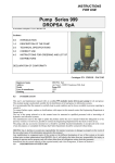
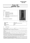
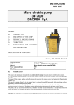
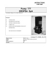
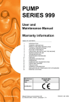
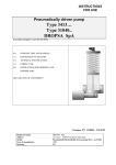
INSTRUCTIONS
FOR USE
Pneumatically driven pump
Type 233000 & 234000
DROPSA SpA
In accordance with point 1.7.4, to I, Dir. 98/37 CE
Sections:
0.0
INTRODUCTION AND WARNING
1.0
DESCRIPTION OF THE PUMP
2.0
TECHNICAL SPECIFICATIONS
3.0
CORRECT USE
4.0
DISTRIBUTORS
DECLARATION OF CONFORMITY
Catalogue P/N C2017IE - Wk 23/02
Registered name
Address
Model
Year of manufacture
Marking
0.0
DROPSA SpA
via Croce 1, 20090 Vimodrone (MI), Italy
Pneumatically driven pump 233000 & 234000
1999
CE
INTRODUCTION AND WARNING
This user’s and maintenance manual refers to series 233000 & 234000 pneumatically driven pumps, for use in
mineral oil or grease lubrication systems.
It is recommended that this manual is carefully kept in good condition and is always available to persons requiring to
consult it.
To request further copies, updates or clarifications with respect to this manual contact the Engineering Department at
Dropsa SpA.
The use of the pump referred to in this manual must be entrusted to qualified personnel with a knowledge of
hydraulics, mechanical and electrical systems; the non-observance of the information given in this manual or the
improper use of the equipment by non-qualified or non-authorised personnel can put persons or the environment at
risk due to the escape of fluids under pressure.
It is of extreme importance that the instructions for use are read and understood both by the operators and
maintenance personnel, in cases of doubt please contact the area representative or our “Customer Service”
department.
The manufacturer reserves the right to update the product and/or the user’s manual without the obligation to revise
previous versions. It is however, possible to contact the Engineering Department for the latest revision in use.
It is the responsibility of the installer to utilise tubing suitable for the system; the use of unsuitable tubing can
generate problems with the pump, risks to persons and cause pollution.
The loosening of connections can cause serious safety problems and all such connections should be checked before
and after installation and tightened if necessary.
Never exceed the maximum operating pressure values allowed for the pump and the components to which it is
connected.
Before any maintenance or cleaning operations, close off the air supply and release the pressure from the pump and
the tubing to which it is connected.
Do not subject the pump, the tubing or other parts under pressure to violent impacts; damaged tubing or connections
are dangerous and should be replaced.
After prolonged periods of inactivity, ensure the tightness of all connections subjected to pressure.
It is required that personnel make use of protection devices, clothing and necessary tools, suitable to the place and
employment of the pump both while in operation and during the undertaking of maintenance tasks.
The pump, and any accessories mounted on it, should be carefully checked immediately on receipt and in the event
of any discrepancy or complaint the Dropsa SpA Sales Department should be contacted without delay.
DROPSA S.p.A. declines to accept any responsibility for injuries to persons or damage to property in the event of
the non-observance of the information presented in this manual.
Any modification to component parts of the system or the different destination of use of this system or its parts
without prior written authorisation from DROPSA S.p.A. will absolve the latter from any responsibility for injury or
damage to persons and/or property and will release them from all obligations arising from the guarantee.
The list of importers and instructions for ordering the required model are shown in Section 4.
1.0
DESCRIPTION OF THE PUMP
These powerful, robust and long lasting pumps, mounted on commercial drums, are used for transferring light
greases, lubricants and other non-corrosive fluids or, fitted with a flexible hose and gun, for filling grease cups or
small tanks in the industrial and automotive fields.
Another interesting application of this type of pump is in the lubrication field where its capacity to deliver large
quantities at a high working pressure renders it particularly suitable for feeding centralised progressive systems.
The pump is made up of a motor assembly with a synthetic rubber piston, particularly resistant to abrasion, moved
from top to bottom (and vice-versa) by a compressed air jet, and a pump rod with a chromed piston, connected to the
motor piston.
The lubricant is primed on the upstroke of the piston filling the lower chamber of the pump rod or the priming
chamber and from here, through a non-return valve, passes to the upper chamber (high pressure chamber).
In the successive downstroke phase, the piston forces this quantity of lubricant through the pump outlet and,
simultaneously, refills the priming chamber so repeating the cycle.
The pressure with which the lubricant is delivered is 40 times that of the command air, while the flow rate, at a
temperature of 20°C, with an air pressure of 10 bar, is in the order of 400 grams of lubricant a minute.
The following accessories can be supplied on request:
Pressure disk – to be used when the pump is mounted directly on a commercial grease drum. This disk acts to
maintain the grease compact and to avoid the formation of air bubbles in the feed line so prejudicing the the
functioning of the system.
Lid – made for mounting this type of pump, substituting the original drum lid.
Suction filter – to be mounted on the pump dip tube as the lubricants supplied in commercial drums are not always
free from impurities.
Air treatment assemblies – Specifications: double action filter in the air line. Air regulator for a constant air
pressure. Lubricator with a constant air-oil ratio. Control of the oil flow – viscosity of the oil up to 110 cSt.
The versions for double lines are complete with a tank of 5 Kg/lt. In sheet steel, minimum level electrical contact,
filling valve, hydraulic inverter and pressure gauge; these are suitable for the lubrication of small to medium sized
machinery.
1.1
Accessories
Nipple to connect pump to the flexible hose: Part N°. 2513006 - Ø ½” 27 threaded for 1” (flex side)
R ¼ UNI ISO 7/1 (gas) pump side
Connector, rotary: Part N° 2037659
C2017IE - Pneumatically driven pump - Rev. 1
June 2002
Page 2 of 9
Gun, greasing: Part N° 1151000
Filter, suction: Part N° 234063
Snap connector: Part N° 919000
Hose, flexible, air: Part N° 101100 + length in cm (overall) – R ¼ gas, Ø flex 8x17
Hose, flexible, lubricant: Part N° 2513021 + length in cm (overall) - ½ “ 27 threaded for 1”
2.0
TECHNICAL SPECIFICATIONS
Compression ratio:
Command air pressure:
Lubricant outlet :
Compressed air inlet:
Delivery flow rate:
40:1
minimum 4 bar (0.4 MPa) – maximum 10 bar (1 MPa) –
recommended 7 bar (0.7 MPa)
G 1/4 UNI-ISO 228/1 (1/4 Gas)
G 1/4 UNI-ISO 228/1 (1/4 Gas)
400 gr. of grease/min with an air pressure of 10 bar
HYDRAULIC DIAGRAM 233000
2.1
HYDRAULIC DIAGRAM 234000
Methods of commanding the pump
It is possible to command the pump manually with a simple valve or automatically utilising a 2 or 3 way
solenoid valve.
C2017IE - Pneumatically driven pump - Rev. 1
June 2002
Page 3 of 9
2.2
Fixing dimensions
DIMENSIONS 233000
CODE &
TYPE
WEIGH
T
DIMENSIONS
DIMENSIONS 234000
Drum
Part N°
Pump
Part N°
Air Motor
Part N°
Pump rod
Length
Dip tube
Part N°
Lid
Part N°
Pressure
disc
Part N°
pump +
access.
*Pump complete with lid and pressure disc
2.3
Other data
Viscosity of lubricant at operating temperature (oil)
From 15 - 2000 cSt
Max. density of grease which can be pumped at operating NLGI 1
temperature
Operating temperature
+ 5 - + 80 °C
Operating humidity
90 % relative humidity
Storage temperature
- 20 - + 50 °C
Noise pressure level
< 75 dB(A)
C2017IE - Pneumatically driven pump - Rev. 1
June 2002
Page 4 of 9
3.0
CORRECT USE
3.1
Putting into service
♦ The unit may be used, opened and repaired only by specialised personnel.
♦ The pump MUST NOT be submersed in fluids or utilised in environments which are particularly aggressive or
explosive/inflammable if not prepared for this purpose beforehand by the supplier.
♦ For correct fixing verify the distance between centres shown in the diagram in Section 2.2.
♦ Use gloves and safety glasses as required in the lubrication oil safety chart.
♦ DO NOT use aggressive lubricants with NBR gaskets and seals; if in doubt consult the Engineering Department
of Dropsa SpA, who will provide a chart with the details of recommended oils..
♦ DO NOT ignore dangers to health and observe all hygiene standards.
♦ WARNING! All electrical components must be grounded. This refers to both electrical components and control
devices. In this regard ensure that the ground cable is correctly connected. For reasons of safety the ground cable
must be approx. 100 mm longer than the phase cables. In the event of accidental detachment of the cable, the
ground terminal must be the last to be removed.
☞ action to be taken prior to start up
Verify the integrity of the pump;
Insert the pump in the drum ensuring there are no air bubbles in the grease;
Verify that the pump is at operating temperature and the tubing free from air bubbles;
Verify the integrity of the supply line
Check that any electrical connections have been effected correctly (CEI 64/8, IEC 364);
Check that any solenoid valves or level indicators are correctly connected to the control panel.
Unless otherwise specified by the customer, the minimum level is supplied with the contacts normally
closed. Where the user requires the contacts to be normally open it is necessary to open the tank and to
invert the operating direction if the float.
3.2
Use
1.
2.
3.
4.
5.
3.3
verify the settings on the control panel, where fitted;
press the start button of the machine to which the pump is connected;
verify the starting of the pump;
verify the adequate lubrication of the machine (if doubt exists as to the correct functioning consult the
Engineering Department of Dropsa SpA to request test procedures).
Where used as a transfer pump verify that the flow of the lubricant is continuous and constant.
Transport and storage
Transport and storage is effected in a cardboard package.
No particular precautions are required except as noted on the package itself.
Handling can be effected by one person.
!
Lift the unit with taking account of the right way up indicated on the cardboard carton
!
The machine components can withstand temperatures, during storage, from -20 to +50°C; however, in
order to avoid damage, starting of the machine should occur at a minimum temperature of -5°C.
3.4
Assembly/Disassembly
C2017IE - Pneumatically driven pump - Rev. 1
June 2002
Page 5 of 9
Assembly:
No provisions are made for the disassembly of the pump.
1.
2.
3.
4.
5.
6.
Carefully check the integrity of the drum, any dents could impend the movement of the pressure disc.
Open the lid of the drum and level the surface of the grease
Clamp the pump to the appropriate the drum lid.
Place the lid with the pump on the drum taking care to secure it with the clamping screws.
Connect the flexible hose to the delivery outlet of the pump; check that it is suitable for the operating
pressure and flow rate.
Connect the pump to the compressed air supply.
Disassembly:
The pump has been designed and constructed to require the minimum of maintenance.
1.
2.
3.
Disconnect the air supply and the lubricant delivery hose from the pump;
if required the pump rod can be emptied by operating the pump with the rod uppermost. DANGER!
(ensure hands are not near the suction inlet during the pump operation).
Clamp the pneumatic motor head in a vice and unscrew the dip tube; take care of the joint lockpin
which can easily come out and be lost in the lubricant.
Separate the 2 components; both can be overhauled or replaced without any difficulties.
Where the machine is to be scrapped, do not dispose of potentially polluting parts in the environment,
following local regulations for their correct disposal.
At the time of the machine being scrapped it is necessary to remove and destroy the identification plate and all other
relative documents.
3.5
Regulation
The only parameter which can be modified is the pressure; to modify the value increase or decrease the pressure of
the command air supply.
3.6
Maintenance
!
Locate the machine in conditions which facilitate easy access.
Utilise individual protection to avoid contact with mineral oil or grease.
Having undergone rigorous testing by ourselves, the pump does not require any further maintenance. The use of
lubricants free from impurities is recommended and the periodic careful cleaning of the component parts of the
pump and inspection for any signs of damage.
The machine does not require any special tools to carry out checks or maintenance tasks, However, it is
recommended that only tools suitable for the tasks and in good condition should be utilised (DPR 547/55) to avoid
injury to persons or damage to machine parts.
3.7
Repairs
The following diagnostic table indicates the main anomalies which may be encountered, the probable causes and
possible solutions.
The anomalies shown are:
• the pneumatic motor fails to function
• the pneumatic motor functions but fails to deliver product
• the pump fails to maintain pressure
In case of doubts and/or problems which cannot be resolved do not attempt to disassemble parts of the machine but
contact the Engineering Department of DROPSA S.p.A.
C2017IE - Pneumatically driven pump - Rev. 1
June 2002
Page 6 of 9
PROBABLE CAUSE
SYMPTOM
The pneumatic motor fails
to function.
REMEDY
•
Problems with the supply
line.
•
Check the air supply connections. Check
the air treatment assembly.
•
Pump rod blocked
•
Remove the rod and check that it slides
freely. Dissemble and clean if necessary.
•
Internal damage
•
Disconnect the rod and check that the
motor functions; if necessary disassemble,
clean and replace any damaged parts.
The pneumatic motor
•
functions but fails to deliver
product
•
lack of lubricant in the drum •
The pump fails to maintain
pressure.
3.8
Refill or replace the drum
•
Disassemble the rod and clean internally.
•
The suction is impeded by
impurities
Valve or seals worn.
•
Disassemble the rod, clean internally and
replace any worn components.
•
Valves or seals worn.
•
Disassemble the rod, clean internally and
replace any worn components.
Dangers present in use
The verification of conformity with the essential safety requirements and regulations of the Machine Directive is
effected by means of the compilation of a check list which has been pre-prepared and is contained in the technical
file.
The lists which are utilised are of three types:
•
list of dangers (as in EN 414 referring to EN 292)
•
application of essential safety requirements (Machine Dir. - att. 1, part 1)
•
electrical safety requirements (EN 60204-1)
The following is a list of dangers which have not been fully eliminated but which are considered acceptable:
♦
it is possible to encounter low pressure oil squirts during maintenance (for this reason appropriate
protective clothing must be worn).
♦
contact with oil -> see the requirements for the use of suitable personal protective clothing.
♦
pre-loaded springs in the control cylinder and, where fitted, in the tank.
♦
use of unsuitable lubricant -> the characteristics of the fluid are shown on the pump and in the manual
(in case of doubt contact the Eng. Dept of Dropsa Spa)
♦
protection against direct and indirect contact must be provided by the user
♦
given the purpose of the pump it must always be functioning; for this reason it is necessary to pay
attention to the electrical connections which, in the case of a power failure, the customer’s machine is
restarted only by means of a reset, while the lubrication pump is able to restart.
♦
During installation and maintenance stages there exists the danger of cutting with the suction fitting.
C2017IE - Pneumatically driven pump - Rev. 1
June 2002
Page 7 of 9
INADMISSIBLE FLUIDS
Fluids
Lubricants with abrasive additives
Lubricants with silicon additives
Petrol – solvents – inflammable liquids
Corrosive products
Water
Food products
4.0
Danger
High wear rate of contacted parts
Seizure of the pump
Fire – explosion – damage to seals
Corrosion of the pump – injury to persons
Oxidation of the pump
Contamination of the product itself
Instructions for ordering and distributors
Versions available
Part N°
pump
234000
For drums
of Kg/lt
5
Syst
Lubricant
to be pumped
Grease NLGI 1
Part N°
dip tube
234050
Pump
weight
5.5 kg
26
234150
20
26
Grease NLGI 1
234160
6 kg
234200
56
26
Grease NLGI 1
234210
7 kg
234250
180
26
Grease NLGI 1
234260
7.5 kg
234125
234126
233310
233330
233300
20
180
5 supplied
5 supplied
5 supplied
26
26
26
26
Grease NLGI 1
Grease NLGI 1
Grease NLGI 1
Oil 1500 cst
02
Grease NLGI 1
234160
234260
234050
234050
234050
9 Kg
23 Kg
18.3 Kg
18.5 Kg
25 kg
233305
5 supplied
02
Oil 1500 cst
234050
20 kg
254500
20 supplied
26
Grease NLGI 1
234160
35 Kg
C2017IE - Pneumatically driven pump - Rev. 1
June 2002
Note
Air attachment with snap connector
(supplied)
Air attachment with snap connector
(supplied)
Air attachment with snap connector
(supplied)
Air attachment with snap connector
(supplied)
With lid and pressure disc
With lid and pressure disc
With minimum level
With minimum level & 2 way valve
With hydraulic inverter, min level &
gauge
With hydraulic inverter, min level &
gauge
Con trolley, 2 m hose & gun
Page 8 of 9
CE Declaration Of Conformity
Manufacturer :
DROPSA SpA
Company
Via Croce, 1 - 20090 Vimodrone (MI), Italy
Address
02 - 250791
Telephone
It is certified that:
Pneumatically driven pump series 233000 and 234000
The machine:
∗ is manufactured in conformity with the DIRECTIVE OF THE COUNCIL OF THE EUROPEAN COMMUNITY concerning
∗
the harmonisation of member states legislation relative to machines (98/37 CE + 91/368/CEE), EMC (89/336/CEE) and BT
(73/23/CEE) and relative amendments.
is manufactured in accordance with the following standards and harmonised technical specifications:
EN 292/1, EN 292/2, EN 50081-2, EN 50082-2, CEI EN 60204-1, EN 1050.
Technical manager
Product manager
DROPSA SpA
Company
Ing. Walter Divisi
Name
- Vimodrone (MI) - Italy
February 1999
Date
Signature
DROPSA DISTRIBUTORS
C2017IE - Pneumatically driven pump - Rev. 1
June 2002
Page 9 of 9