1
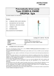
INSTRUCTIONS
FOR USE
Pneumatically driven pump
Type 3413…
Type 31040..
DROPSA SpA
In accordance with point 1.7.4, to I, Dir. CEE 89/392
0.0
INTRODUCTION AND WARNING
1.0
DESCRIPTION OF THE PUMP
2.0
TECHNICAL SPECIFICATIONS
3.0
CORRECT USE
4.0
INSTRUCTIONS FOR ORDERING AND
DISTRIBUTORS
DECLARATION OF CONFORMITY
Catalogue P/N C2008IE - Wk 05/99
Registered name
Address
Model
Year of manufacture
Marking
DROPSA SpA
via Croce 1, 20090 Vimodrone (MI), Italy
Pneumatically/hydraulically driven pump 3413--- & 31040
1990
CE
0.0
INTRODUCTION AND WARNING
This user’s and maintenance manual refers to series 3413--- and 31040 pneumatically driven pumps, for use in
mineral oil or grease lubrication systems.
It is recommended that this manual is carefully kept in good condition and is always available to persons requiring
to consult it.
To request further copies, updates or clarifications with respect to this manual contact the Engineering Department
at Dropsa SpA.
The use of the pump referred to in this manual must be entrusted to qualified personnel with a knowledge of
hydraulics, mechanical and electrical systems; the non-observance of the information given in this manual or the
improper use of the equipment by non-qualified or non-authorised personnel can put persons or the environment at
risk due to the escape of fluids under pressure.
It is of extreme importance that the instructions for use are read and understood both by the operators and
maintenance personnel, in cases of doubt please contact the area representative or our “Customer Service”
department.
The manufacturer reserves the right to update the product and/or the user’s manual without the obligation to revise
previous versions. It is however, possible to contact the Engineering Department for the latest revision in use.
It is the responsibility of the installer to utilise tubing suitable for the system; the use of unsuitable tubing can
generate problems with the pump, risks to persons and cause pollution.
The loosening of connections can cause serious safety problems and all such connections should be checked before
and after installation and tightened if necessary.
Never exceed the maximum operating pressure values allowed for the pump and the components to which it is
connected.
Before any maintenance or cleaning operations, close off the air supply and release the pressure from the pump and
the tubing to which it is connected.
Do not subject the pump, the tubing or other parts under pressure to violent impacts; damaged tubing or
connections are dangerous and should be replaced.
After prolonged periods of inactivity, ensure the tightness of all connections subjected to pressure.
It is required that personnel make use of protection devices, clothing and necessary tools, suitable to the place and
employment of the pump both while in operation and during the undertaking of maintenance tasks.
The pump, and any accessories mounted on it, should be carefully checked immediately on receipt and in the event
of any discrepancy or complaint the Dropsa SpA Sales Department should be contacted without delay.
DROPSA S.p.A. declines to accept any responsibility for injuries to persons or damage to property in the event of
the non-observance of the information presented in this manual.
Any modification to component parts of the system or the different destination of use of this system or its parts
without prior written authorisation from DROPSA S.p.A. will absolve the latter from any responsibility for injury or
damage to persons and/or property and will release them from all obligations arising from the guarantee.
The list of importers and instructions for ordering the required model are shown in Section 4.
1.0
DESCRIPTION OF THE PUMP
These pumps utilise compressed air to control the delivery of the lubricant and are ideal for lubrication systems
installed on machines already supplied with compressed air.
The solenoid control valve must be:
3 way (line-cylinder-discharge) for single action pumps
4 way (line-cylinder-discharges) for double action pumps
Deliverable lubricant: mineral, not containing abrasive substances.
Compressed air supply pressure: min. 4 bar (0.4 MPa) – max 8 bar (0.8 MPa)
Tank filling valve: G 1/2 UNI-ISO 228/1 – only for pump 3413026 hydraulic connection
Lubricant outlet: Rp 1/4 UNI-ISO 7/1
Compressed air inlet:
for pump type 3413… G 1/8 UNI-ISO 228/1 fitting for 6 mm tube
for pump type 31040.. G 1/4 UNI-ISO 228/1 fitting for 8 mm tube
Filter for oil recovery (where fitted) in metal and/or paper.
Magnet type electrical minimum oil level indicator. Maximum operating temperature: +80 °C
C20008IE – Pneumatically driven pump - Rev. 0
February 99
Page 2 of 9
1.1
2.0
Accessories
As per specific request.
TECHNICAL SPECIFICATIONS
2.1
Methods of commanding the pump
Manual push-button control
Supply
Discharge
3-way solenoid valve control
Supply
Discharge
Mechanical roller or cam bar control
Supply
Discharge
C20008IE – Pneumatically driven pump - Rev. 0
February 99
Page 3 of 9
2.2
Fixing dimensions
2.3
Other data
NLGI grease rating at working temperature
Viscosity of the lubricant at working temperature
Working temperature
Working humidity
Preservation temperature
Sound pressure level
3.0
CORRECT USE
3.1
Putting into service
see table at sub-section 4.0
Between 15 - 2000 cSt
+ 5 - + 80 °C
90 % relative humidity.
- 20 - + 50 °C
< 70 dB(A)
♦ The unit may be used, opened and repaired only by specialised personnel.
♦ The pump MUST NOT be submersed in fluids or utilised in environments which are particularly aggressive or
explosive/inflammable if not prepared for this purpose beforehand by the supplier.
♦ For correct fixing verify the distance between centres shown in the diagram in Section 2.2.
♦ Use gloves and safety glasses as required in the lubrication oil safety chart.
♦ DO NOT use aggressive lubricants with NBR gaskets and seals; if in doubt consult the Engineering Department
of Dropsa SpA, who will provide a chart with the details of recommended oils.
♦ DO NOT ignore dangers to health and observe all hygiene standards.
♦ WARNING! All electrical components must be grounded. This refers to both electrical components and control
devices. In this regard ensure that the ground cable is correctly connected. For reasons of safety the ground cable
must be approx. 100 mm longer than the phase cables. In the event of accidental detachment of the cable, the
ground terminal must be the last to be removed.
C20008IE – Pneumatically driven pump - Rev. 0
February 99
Page 4 of 9
+
action to be taken prior to start up
Verify the integrity of the pump;
Fill the tank with suitable lubricant (min/max indication on the tank);
Verify that the pump is at operating temperature and the tubing free from air bubbles;
Check that the electrical connections have been effected correctly (CEI 64/8, IEC 364);
Verify the correct connections of any level and pressure switches to the control panel
3.2
Use
1.
2.
3.
4.
3.3
verify the settings on the control panel, where fitted;
press the start button of the machine to which the pump is connected;
verify the starting of the pump;
verify the adequate lubrication of the machine (if doubt exists as to the correct functioning consult the
Engineering Department of Dropsa SpA to request test procedures).
Transport and storage
Transport and storage is effected in a cardboard package.
No particular precautions are required except as noted on the package itself.
Handling can be effected by one person.
!
Lift the unit with taking account of the right way up indicated on the cardboard carton
!
The machine components can withstand temperatures, during storage, from -20 to +50°C; however, in
order to avoid damage, starting of the machine should occur at a minimum temperature of -5°C..
3.4
Assembly/Disassembly
No pump assembly operations are envisaged.
For wall or floor mounting ensure adequate space is available (as shown in the installation diagram) to avoid
abnormal postures and possible impacts; four fixing holes are provided with different characteristics depending on
the version (see section 2.2)
Subsequently it will be necessary, as previously described, to connect the pump to the machine hydraulically and
then to connect the control panel.
During the disassembly phase ensure the tank is empty.
Disconnect the electrical, hydraulic and pneumatic parts.
Where the machine is to be scrapped, do not dispose of potentially polluting parts in the environment,
following local regulations for their correct disposal.
At the time of the machine being scrapped it is necessary to remove and destroy the identification plate and all
other relative documents.
3.5
Regulation
The only parameter which can be modified is the pressure; to modify the value increase or decrease the pressure of
the command air/hydraulic supply.
3.6
Maintenance
!
Locate the machine in conditions which facilitate easy access.
Utilise individual protection to avoid contact with mineral oil or grease.
Having undergone rigorous testing by ourselves, the pump does not require any further maintenance. The use of
lubricants free from impurities is recommended and the periodic careful cleaning of the component parts of the
pump.
C20008IE – Pneumatically driven pump - Rev. 0
February 99
Page 5 of 9
Disassembly must be effected in the following manner:
1.
2.
3.
4.
disconnect the tubing attached to the pump.
remove the fixing screws and remove the tank, paying PARTICULAR ATTENTION to models containing a
grease pressure loading spring (it could be under pressure– in this case empty the remaining lubricant
first).
remove the pump and any filters.
unscrew the pneumatic cylinder of the pump paying PARTICULAR ATTENTION to the loading of the
spring; the component parts of the pump unit can then be disassembled.
In this way all component parts of the pump unit can be removed allowing the disassembly and cleaning of the
release and suction valves.
All pieces should be washed in petrol and lubricated prior to reassembly.
The following should be checked periodically:
VERIFY
The state of lubrication
The oil level
The cleanliness of the suction filter
The cleanliness of the loading/return filter
That the tank is clean and the bottom free from
deposits
WORK CYCLES
100
200
400
400
600
The machine does not require any special tools to carry out checks or maintenance tasks, However, it is
recommended that only tools suitable for the tasks and in good condition should be utilised (DPR 547/55) to avoid
injury to persons or damage to machine parts.
3.7
Repairs
The following diagnostic table indicates the main anomalies which may be encountered, the probable causes and
possible solutions.
The anomalies shown are:
• the pump fails to deliver sufficient oil or no oil at all
• the pump fails to deliver oil at the prescribed pressure
In case of doubts and/or problems which cannot be resolved do not attempt to disassemble parts of the machine but
contact the Engineering Department of DROPSA S.p.A.
C20008IE – Pneumatically driven pump - Rev. 0
February 99
Page 6 of 9
INDICATION
The pump does not deliver oil or
does not deliver oil in the exact
quantity prescribed
PROBABLE CAUSE
REMEDY
•The oil in the tank is below the
minimum level
• Fill the tank with oil without
exceeding the MAX level line
•The suction filter is dirty or
blocked
• Remove the pump from the
tank, remove the filter, wash it
and blow it through with
compressed air.
•The pump control valve fails to
discharge
• Check that the pump control
valve is a 3-way type for the
single action pump and 4 way
for the double action; verify that
the valve regularly discharges
compressed air oil from the
pump chamber.
• The internal connections are loose • Tighten all connections
ensuring there are no leaks
The pump does not deliver oil at
the prescribed pressure
3.8
•Incorrect regulation of the
supply air/oil.
• Regulate the pressure of the
oil/air within the range shown
in the general characteristics,
taking into account the
compression ratio.
Dangers present in use
The verification of conformity with the essential safety requirements and regulations of the Machine Directive is
effected by means of the compilation of a check list which has been pre-prepared and is contained in the technical
file.
The lists which are utilised are of three types:
•
list of dangers (as in EN 414 referring to EN 292)
•
application of essential safety requirements (Machine Dir. - att. 1, part 1)
•
electrical safety requirements (EN 60204-1)
The following is a list of dangers which have not been fully eliminated but which are considered acceptable:
♦
it is possible to encounter low pressure oil squirts during maintenance (for this reason appropriate
protective clothing must be worn).
♦
contact with oil -> see the requirements for the use of suitable personal protective clothing.
♦
pre-loaded springs in the control cylinder and, where fitted, in the tank.
♦
use of unsuitable lubricant -> the characteristics of the fluid are shown on the pump and in the manual
(in case of doubt contact the Eng. Dept of Dropsa Spa)
♦
protection against direct and indirect contact must be provided by the user
♦
given the purpose of the pump it must always be functioning; for this reason it is necessary to pay
attention to the electrical connections which, in the case of a power failure, the customer’s machine is
restarted only by means of a reset, while the lubrication pump is able to restart.
♦
take care NOT TO clean with alcohol
C20008IE – Pneumatically driven pump - Rev. 0
February 99
Page 7 of 9
INADMISSIBLE FLUIDS
Fluids
Lubricants with abrasive additives
Lubricants with silicone based additives
Petrol – solvents – inflammable liquids
Corrosive products
Water
Food substances
Danger
High wear rate of contacted parts
Seizure of the pump
Fire – explosion – damage to seals
Corrosion of the pump– injury to persons
Oxidation of the pump
Contamination of the substances themselves
4.0 Instructions for ordering and distributors
Part
number
Control
Suitable
for
Lub.
Ratio
3413001
Pneum. S.A.
NLGI 2
30/1
3413002
Pneum. S.A.
NLGI1
30/1
3413003
Pneum. S.A.
NLGI2
30/1
3413005
Pneum. S.A.
NLGI3
30/1
3413007
Pneum. S.A.
NLGI1
30/1
3413012
Pneum. S.A.
NLGI1
30/1
3413014
Pneum. S.A.
NLGI1
30/1
3413016
Pneum. S.A.
NLGI1
30/1
3413018
Pneum. S.A.
NLGI1
30/1
3413019
Pneum. S.A.
NLGI3
30/1
3413026
Pneum. S.A.
NLGI2
30/1
3103014
Pneum. D.A.
OIL
25/1
3104030
Pneum. D.A.
NLGI3
25/1
3104040
Pneum. D.A.
NLGI3
25/1
3104050
Pneum. D.A.
NLGI1
25/1
S.A. = single action - D.A. = double action
Tank
Flow
min.
L/Kg
cm³
level
2
5
1
5
1
5
10
5
3
10
2
5
5
10
5
0.5-2
0.5-2
0.5-2
0.5-2
0.5-2
0.5-2
0.5-2
0.5-2
0.5-2
0.5-2
2
6-15
6-15
6-15
6-15
NO
YES
NO
YES
NO
YES
NO
YES
YES
YES
YES
YES
YES
YES
YES
Part
Height
Length
number
mm
mm
3413001
579/864*
280
3413002
524/754*
280
3413003
357/454*
280
3413005
680
280
3413007
334/474*
280
3413012
558
280
3413014
885
280
3413016
558
280
3413018
498
280
3413019
990
280
3413026
470
280
3103014
485
346
3104030
690
346
3104040
995
346
3104050
590/820*
346
* the two height values refer to tank empty/tank full
C20008IE – Pneumatically driven pump - Rev. 0
Characteristics
with spring
with spring
pressurised tank
with loading filter
pressurised tank
fixed flow, transp. tank with spring
max. level indicator
pressurised tank
pressurised tank
Depth
mm
150
170
150
192
150
160
310
170
160
192
160
120
192
192
170
February 99
Weight
Kg
7.7
11.5
6.2
19.5
5.3
11.8
26.5
12
11.2
27.3
9.8
15.5
27.5
35.5
19.5
Page 8 of 9
CE Declaration Of Conformity
Manufacturer :
DROPSA SpA
Company
Via Croce, 1 - 20090 Vimodrone (MI), Italy
Address
02 - 250791
Telephone
The machine:
It is certified that:
Pneumatically driven pump, type 3413… and 31030..
∗ is manufactured in conformity with the DIRECTIVE OF THE COUNCIL OF THE EUROPEAN COMMUNITY concerning
the harmonisation of member states legislation relative to machines (89/392/CEE + 91/368/CEE), EMC (89/336/CEE) and
BT (73/23/CEE) and relative amendments.
∗ is manufactured in accordance with the following standards and harmonised technical specifications:
EN 292/1, EN 292/2, EN 50081-2, EN 50082-2, CEI EN 60204-1, EN 1050.
Technical manager
Product manager
DROPSA SpA
Company
Ing. Walter Divisi
Name
- Vimodrone (MI) - Italy
February 1999
Date
Signature
DROPSA DISTRIBUTORS
C20008IE – Pneumatically driven pump - Rev. 0
February 99
Page 9 of 9