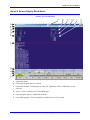
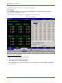
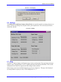
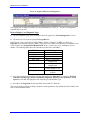
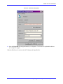
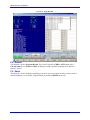
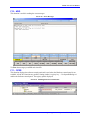
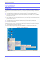
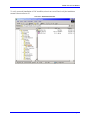
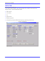
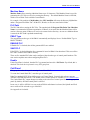
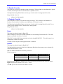
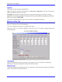
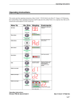
1
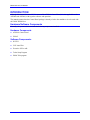
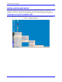
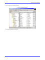
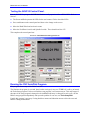
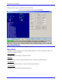
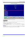
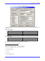
^1 USER MANUAL
^2 PMAC NC-32
^3 Operating Instructions
^4 3Ax-ACC33N-xUxO
^5 April 23, 2003
Single Source Machine Control
Power // Flexibility // Ease of Use
21314 Lassen Street Chatsworth, CA 91311 // Tel. (818) 998-2095 Fax. (818) 998-7807 // www.deltatau.com
PMAC NC-32 User Manual
Table of Contents
INTRODUCTION .......................................................................................................................................................1
Hardware/Software Components...............................................................................................................................1
Hardware Components .........................................................................................................................................1
Software Components:..........................................................................................................................................1
INSTALLATION AND SETUP .................................................................................................................................3
Verification of the NC Installation S/W ....................................................................................................................3
Testing the ADV810 Control Panel. .........................................................................................................................5
Running the CNC AutoPilot Program. ......................................................................................................................5
OPERATING INSTRUCTIONS FOR DELTA TAU NC FOR WINDOWS........................................................7
Getting Started...........................................................................................................................................................7
General Screen Display Breakdown..........................................................................................................................8
Function Keys .........................................................................................................................................................10
F2 – Pos..............................................................................................................................................................10
F3 – Prog............................................................................................................................................................11
F4 -- Offset..........................................................................................................................................................11
F5 – Tools...........................................................................................................................................................13
F6 – Settings .......................................................................................................................................................14
F7 – Diag............................................................................................................................................................14
F8 – Rewind........................................................................................................................................................17
F9 – Editor..........................................................................................................................................................17
F10 – MSG..........................................................................................................................................................18
F11 – OPER........................................................................................................................................................18
Operational Modes ..................................................................................................................................................19
Manual Mode......................................................................................................................................................19
Auto Mode...........................................................................................................................................................20
MDI Mode...........................................................................................................................................................22
DNC Mode..........................................................................................................................................................23
OPERATING INSTRUCTIONS FOR ADV810 CONTROL PANEL .................................................................27
CNC AUTOPILOT....................................................................................................................................................29
Introduction .............................................................................................................................................................29
How to Use CNC AutoPilot ....................................................................................................................................31
Axis - Motor Definitions .....................................................................................................................................32
Position Units .....................................................................................................................................................32
Display Format...................................................................................................................................................32
Reset All..................................................................................................................................................................32
Std PLC TAB ..........................................................................................................................................................33
Machine Name ....................................................................................................................................................34
PLC Path ............................................................................................................................................................34
PMAC Type.........................................................................................................................................................34
ENABLE PLC .....................................................................................................................................................34
SAVE PLC...........................................................................................................................................................34
Enable.................................................................................................................................................................34
Cntl Panel ................................................................................................................................................................34
Adv. Settings .......................................................................................................................................................35
Override..............................................................................................................................................................35
% Spindle Override.............................................................................................................................................36
% Feedrate Override ..........................................................................................................................................36
Home...................................................................................................................................................................36
Handle ................................................................................................................................................................36
Spindle ................................................................................................................................................................37
Machine Setup Tab..................................................................................................................................................37
Table of Contents
i
PMAC NC-32 User Manual
Jog Speed............................................................................................................................................................37
Rapid Speed ........................................................................................................................................................37
Positive S/W Limit...............................................................................................................................................38
Negative S/W Limit .............................................................................................................................................38
Home Offset ........................................................................................................................................................38
Home Speed ........................................................................................................................................................38
Positive Limit Switch ..........................................................................................................................................38
Negative Limit Switch .........................................................................................................................................38
Home Switch .......................................................................................................................................................38
Home on ‘C’ Channel.........................................................................................................................................38
CS Setup..................................................................................................................................................................38
Feed Rate............................................................................................................................................................38
Following Error..................................................................................................................................................38
In Position Band .................................................................................................................................................38
LookAhead ON....................................................................................................................................................38
Function Buttons .....................................................................................................................................................39
PMAC_Setup ......................................................................................................................................................39
Update ................................................................................................................................................................39
Build ...................................................................................................................................................................39
Build & Download..............................................................................................................................................39
CNC AutoPilot- Example........................................................................................................................................40
MyMachine.CFG ................................................................................................................................................42
AUTOPILOT Files..................................................................................................................................................43
MyMachine.H .....................................................................................................................................................43
NC_I_VAR.IVR ...................................................................................................................................................43
INITIALIZE.PLC ................................................................................................................................................43
CNTLPANEL.PLC ..............................................................................................................................................43
OVERRIDE.PLC.................................................................................................................................................43
HOME.PLC ........................................................................................................................................................43
HANDLE.PLC ....................................................................................................................................................43
SPINDLE.PLC....................................................................................................................................................44
OEM.H................................................................................................................................................................44
NCPLC.H............................................................................................................................................................44
ADVCNTLU.H ....................................................................................................................................................44
APPENDIX A.............................................................................................................................................................45
ii
Table of Contents
PMAC NC-32 User Manual
INTRODUCTION
Although this manual discusses NC-2 in terms of the ADV810 Control Panel, it is also applicable to the
ADV800 and ADV600, with regard to software and operation.
The manual assumes that the Control Panel package is already wired to the machine or is to be used with
the UMAC DEMO box.
Hardware/Software Components
Normally, the system is delivered with the following components installed:
Hardware Components
•
ADV810 Control Panel
•
UMAC
Software Components:
•
NCUI32
•
CNC Auto Pilot
•
Executive S/W to talk
•
Turbo Setup Program
•
PMAC Plot program
Introduction
1
PMAC NC-32 User Manual
2
Introduction
PMAC NC-32 User Manual
INSTALLATION AND SETUP
Verify the installation according to the following sections. If the NCUI32 software is not already
installed, use DeltaTau’s NC software CD to install it. The installation software gives step-by-step
instructions. NCUI can be installed for Mill (Machining Center) or Lathe (Turning Center) application.
Verification of the NC Installation S/W
Screen 1 displays the different applications that can be selected after successful installation of the CD.
Screen 1. Available Applications
Installation and Setup
3
PMAC NC-32 User Manual
Screen 2 displays the installation structure.
Screen 2. Installation Structure
This completes installation verification.
4
Installation and Setup
PMAC NC-32 User Manual
Testing the ADV810 Control Panel.
Run the SOCLB Test program SOCLB 810 Check to verify operation of the ADV810H/W. Refer to
Screen 3.
•
The Green and Red represent the LEDs for the user buttons. Click to check the LEDs.
•
Press each button on the control panel and observe the change on the screen.
•
Move the Hand Wheel and see that it counts.
•
Move the Feed Rate Override and Spindle Override. These should read 0 to 255.
This completes the control panel test.
Screen 3. SOCLB 810 Check Program Screen
Running the CNC AutoPilot Program.
This program allows setup of the PMAC and NC.
The first time the program is executed, based on the card type (in our case TURBO 2) it will try to launch
the Turbo Setup program. If it does not find the setup program, it will return an error. This may happen if
the name of the setup program is changed or the installation directory is changed. In such a case, run the
PMAC setup program independently and report the problem. In our case, run TurboSetupPRO.
Usually this program is necessary if using brushless motors and induction motors to drive the axes and
PMAC is doing commutation.
Installation and Setup
5
PMAC NC-32 User Manual
On successful return from TurboSetupPRO, finish the remaining AutoPilot Program. This involves
setting up the –
•
Axis – Motor relation
•
PLC Configuration
•
Machine Setup Parameters Configuration
•
PLC to PMAC Build, or Build and Download
For more information, read the CNC AutoPilot manual.
The next step is to RUN NCUI32. This will show basic functionality working and includes:
•
Mode selection
•
AXIS selection
•
Jog
•
Speed selection
•
Handwheel operation
•
All function keys from the ADV810 Panel – Single Step, Optional Stop, Block Del, etc.
This completes the NC Installation and Setup.
6
Installation and Setup
PMAC NC-32 User Manual
OPERATING INSTRUCTIONS FOR
DELTA TAU NC FOR WINDOWS
This section describes the operational interface for Delta Tau NC for windows. It gives a detailed
explanation of each screen and the keys associated with it.
Getting Started
On startup the splash screen is displayed. This includes the software version number and its release date.
This information is useful in reporting any problem to Delta Tau Data Systems’ support team.
Screen 4. PMAC NC-32 Startup Screen
Operating Instructions for Delta Tau NC for Windows
7
PMAC NC-32 User Manual
General Screen Display Breakdown
This section discusses the screen components. Refer to Screen 5.
Screen 5. Screen Components
A. Application Name.
B. Current part program file for execution.
C. Current tool number. On Startup this is always T0. Updated in AUTO or MDI mode on tool
selection.
D. Active G codes. Updated in AUTO and MDI mode.
E. Current program position. Updated in all modes.
F. Current Part program. The red rectangle box marks the line to be executed.
8
Operating Instructions for Delta Tau NC for Windows
PMAC NC-32 User Manual
G. Feed rate. This horizontal line has six boxes, as follows:
1 Current feed rate value from Part program. (F code).
2 Actual feed rate. This value may not be the accurate measure, as NC displays the sum of
the actual velocities over the axis.
3 Feed rate mode, feed rate per minute.
4 Current program mode. This can be Cut (G1, G2 etc) or RPD (GO).
5 Current feed rate and rapid override values. These values are same, as there is only one
Feed rate override control.
6
H. Spindle. This horizontal line has six boxes, as follows:
1 Current spindle mode (CW or CCW).
2 Current selected spindle speed (S code).
3 Maximum allowed spindle speed.
4 Current actual spindle speed. This value is accurate if the spindle is close loop.
5 Special spindle mode constant surface speed. If the mode is on, it will display ON.
6 Current spindle override value.
I.
Mode. This horizontal line has four boxes, displaying the current mode, Auto, Manual or MDI.
1 The first, second, and third box display the different information in Manual and AUTO /
MDI. If the mode is AUTO/MDI then these are Single Block, Block Delete and
2
Optional Stop. When the button is selected for one of these functions, the corresponding
3 box is highlighted. If the mode is Manual, then the first box displays current selected
Axis (X, Y, etc.), The second box displays manual sub mode Continuous (CONT) jog,
Handle, Home. The third box displays current speed selection for the Manual sub mode
CONT and HANDLE. These are High, Medium, Low or 0.01, 0.001 or 0.0001.
4 The fourth box displays the current active modal codes in AUTO/MDI, and is empty in
Manual mode.
Operating Instructions for Delta Tau NC for Windows
9
PMAC NC-32 User Manual
J.
Current Status. This last horizontal line can be Warning, Ready, Inhibit, Message or Alarm. It
has five active blocks, as follows:
1 The first and second boxes are active in AUTO or MDI mode. The first box displays the
status of the current part program: Run, Hold, or Stop. The second box displays the
2
motor status, In Position (IPOS) only if all the axes are IN POSITION.
3 The third box displays the program buffer status. If it shows BUF OPEN then the CNC
is ready to load the part program for execution. The BUF OPEN is shown only in
AUTO or MDI mode. In manual mode, this shows BUF CLS (Close).
4 The fourth box displays the type of standard code supported by Delta Tau NC, RS274.
5 The fifth box displays the status of dual port memory, which is an essential component
of Delta Tau NC. If it displays DPR BIN, then the memory is active for loading the part
program. If it displays NO BUFFER, then the part program cannot be loaded.
K. Distance to go. Updated in AUTO or MDI mode.
L. Current execution line number.
M. Active tool length offset number and tool offset number. Updated in AUTO and MDI mode.
N. Active M codes. Updated in AUTO and MDI mode.
O. Current feed rate selection in user unit. Updated in AUTO and MDI mode.
P. Partial part program execution status, repeat count, and number of lines remaining in the
program.
The manual will be referring to M, N, O, and P sections extensively for explaining different NC modes.
Function Keys
There are 12 function keys on the screen, labeled F1 to F12. These function keys are available on every
screen. F1 and F12 keys are smaller in appearance, and are assigned as Menu Navigators. F1 is used to
select the SUB MENU of the selected function key. F12 selects the operation for the current menu.
F2 through F11 are discussed below:
F2 – Pos
Position Display function. On Pressing F1, Machine, Operator, Commanded, Distance-To-Go, &
overall Position Displays are accessed.
Program:
Program Position = Current Machine Positon – Work Offset (G54 – G59) – G92 Offset – Active Tool Offset.
The Program Position display is meaningful only when operating a part program.
Operator:
Operator Position = Current Machine Position – Work Offset
Machine:
The Machine Position is equal to the current axis distance away from the home position.
Commanded:
The Commanded Position is equal to the end position of the current move in program coordinates.
10
Operating Instructions for Delta Tau NC for Windows
PMAC NC-32 User Manual
Dist To Go:
The Dist To Go Position is equal to the difference between the Commanded Position and the Program
Position.
Follow Error:
The Follow Error Position is equal to the difference between the instantaneous desired position and the
actual machine position.
F3 – Prog
Program Display function. This function displays the current selected part program. On restarting the NC,
it displays the last selected part program. On pressing F1, Text, Check and DNC functions are available.
Check displays the part program and other NC display parameters such as Distance-to-Go or Active G
code, etc.
Text displays only the part program.
On selecting the DNC function, NC will accept the the DNC file input on the serial (COM) port. The
properties for the communication port can be set with the Motion/NcRegistry application program.
On pressing F12, two functions are possible: Open and Search.
Open is used for loading a new part program file.
Search is used to search the string in the part program. This can be used to start the program in the middle
or recover the program from the same point where it left stopped. All the non-motion codes are executed.
This can be treated as the MID PROGRAM START function.
F4 -- Offset
F4 allows the machine operator to quickly and easily establish G54 through G59 machine work
coordinate (sometimes referred to as fixture offsets) values.
On pressing F12, Set X, Set Y, Set Z and Set All functions are available to set the work offset.
The work offset G54 to G59 can be select by moving Left or Right Arrow or Tab key.
Operating Instructions for Delta Tau NC for Windows
11
PMAC NC-32 User Manual
Screen 6. Position Display
How to Set the Work Offset
The offset can be changed only in Manual Mode.
1. Move to the appropriate axis position.
2. Select the required Work Offset (G54 to G59).
3. Press F12 to go to offset setting page.
4. Press the appropriate SET button to set the offset. NC software will need confirmation. Press OK to
SET or CANCEL to previous value.
Screen 7. Work Offset Query
12
Operating Instructions for Delta Tau NC for Windows
PMAC NC-32 User Manual
The SET ALL button will set the work offset for all the axes.
F5 – Tools
The Tool Offset Screen allows quick and easy establishment of tool length definitions, gage block
height, and cutter compensation values.
Press the F12 key (function toggle key). Set Z appears on the F2 button.
Screen 8. Tool Offset
How to Set the Tool Offset
The offset can be changed only in Manual Mode.
1. Move to the appropriate Z height position.
2. Press F12 to go to Tool offset setting page.
3. Press SET Z to set the offset. NC software will need confirmation. Press OK to SET or CANCEL to
previous value.
Operating Instructions for Delta Tau NC for Windows
13
PMAC NC-32 User Manual
Screen 9. Z-Axis Query
F6 – Settings
The Setting Screen with Parts Counter & Parts Total screen provides machine operating and power-on
totals, cycle time and cutting time, and parts counter, parts required total. This screen also provides the
current time and date.
Screen 10. Settings
F7 – Diag
The DIAG F7 function displays the Diagnostic page. It shows real time data. This page displays dual port
RAM raw data, Command Status overview, Spindle information and Homing information. This is useful
information for the Delta Tau support team when calling in with a problem.
Delta Tau has created a user definable diagnostic page for user diagnostics. This page can be displayed
by setting Windows registry key entry “UseNewDiagnostics” to ‘1.’
14
Operating Instructions for Delta Tau NC for Windows
PMAC NC-32 User Manual
Screen 11. Registry Editor/UseNewDiagnostics
The registry path is displayed with the key. By default this key is set to ‘0’. It is the User/Integrator's
responsibility to set it to 1.
How to Display User Diagnostic Page
•
The user diagnostic page can be displayed only if the registry key UseNewDiagnostics is set to 1.
•
The next step is to select the appropriate Pages.Dat file.
Delta Tau NC can be used with any kind of PMAC, PMAC1, PMAC2, TURBO, etc. There is a
Pages.Dat file associated with every PMAC. These files are available from the NCUI32 installation, and
can be found in “C:\Program Files\Delta Tau\NC X.xx ,“ where X & x is NC installation version
number. The following table shows the association of these files with PMAC.
File Name
PMAC Type
Pages_1.Dat
Pages_2.Dat
Pages_3.Dat
PMAC 1
PMAC 2
PMAC UltraLite
Pages_5.Dat
PMAC 1 with TURBO
Daughter Card.
PMAC 2 with TURBO
Daughter Card.
PMAC UltraLite with
TURBO Daughter Card.
UMAC with USB –
ADV810
Pages_6.Dat
Pages_7.Dat
Pages_8.Dat
•
Once the appropriate file has been selected, then rename it to Pages.dat. For example: ADV 810
controller - the file Pages_8.Dat is renamed as Pages.Dat. This step is not required for NC4.0
software. It will take the appropriate file depending on which PMAC type.
•
Save/Move the Pages.Dat file into the folder from which NC “Starts In.”
This can be checked easily by looking at properties of the application. By default, the start in folder is the
same as the Installation folder.
Operating Instructions for Delta Tau NC for Windows
15
PMAC NC-32 User Manual
Screen 12. NCUI32.exe Properties
•
Open the Pages.Dat file and append/modify it for diagnostic. The file itself is explainable and there
are examples to support.
When the DIAG mode is selected, the NCUI displays the Pages.Dat file.
16
Operating Instructions for Delta Tau NC for Windows
PMAC NC-32 User Manual
Screen 13. Pages.Dat File
F8 – Rewind
This function is used in Program Rewind. The rewind is possible in MDI or AUTO mode only if
Current Status shows STOP and IPOS. In addition, rewind is possible in Manual mode. (Refer to
Screen 5, item J.)
F9 – Editor
This function is used in loading or modifying a current or new part program. Advance features such as
Search and Replace are available. Program editing is possible in Manual mode only.
Operating Instructions for Delta Tau NC for Windows
17
PMAC NC-32 User Manual
F10 – MSG
This function is useful in reading the error messages.
Screen 14. Error Messages
To Clear the messages press F12 and select F2.
F11 – OPER
This function displays the software control panel and is used when the Hardware control panel is not
available. All the NC functions are possible. Setting window’s registry key — UseOperatorDialog to 1
enables the Software control panel. The registry path is displayed.
Screen 15. Enabling Software Control Panel
18
Operating Instructions for Delta Tau NC for Windows
PMAC NC-32 User Manual
When the software panel is enabled, the NC will look like…
Screen 16. NC Control Screen, Software Panel Enabled
Operational Modes
Delta Tau NC operates in Manual, Auto, MDI or DNC mode.
Manual Mode
This mode is used for setting the part, which includes settings of the work offset and tool offset. The
possible axis operations include…
Axis Selection
The axis can be selected using Axis Selector switch.
Axis JOG
Axis JOG (CONT) is used to jog the selected axis. JOG+ and JOG- are possible choices.
Axis HOME
Axis HOME (Machine Reference) is used to reference the selected axis.
Axis HANDLE
Axis Handle is used for fine and controlled jog moves.
Operating Instructions for Delta Tau NC for Windows
19
PMAC NC-32 User Manual
Auto Mode
Typically, this mode is used for running the part program. Select/Press AUTO to switch to AUTO mode.
The AUTO can be selected from Manual mode if all the axes are stationary, or from MDI mode if the
program is not running and the Current Status (See Screen 5, item J) displays HOLD and IPOS (In
Position). It is not advisable to change the mode while axes are moving or program is running.
How to LOAD a New Program for Execution
The program can be loaded from Auto mode or Manual mode.
NC always loads the last executed part program.
To load a new part program, press F3 – F12 and F2. This will open the dialog Box for loading the file.
Select the required file and close the dialog box by pressing OPEN.
Screen 17. Open File
The Look In folder is the folder set by the NC application to Start In. (See F7 – Diag for information)
It is advisable to END a part program by M2 or M30 code.
Mid Program Start
This is allowed only in AUTO Mode. To start the program in the middle, press F3 – F12 and F3
(Search). The Search Dialog box will appear. Enter the label/string nearest to the required location of
program start and Press Find Next.
20
Operating Instructions for Delta Tau NC for Windows
PMAC NC-32 User Manual
Screen 18. Find
The search will find the label/string and the execution pointer will point to the required program start
location. In the display, it is shown as a blank red square. The solid red band (Screen 19) specifies the last
executed line.
Operating Instructions for Delta Tau NC for Windows
21
PMAC NC-32 User Manual
Screen 19. Last Executed Line
On Cycle Start all the non-motion codes will be executed.
Program Rewind
Program Rewind rewinds the current program and initializes the program counter to the first line of the
program.
Program Rewind is allowed in Manual mode without any condition.
It is allowed in AUTO mode if the program is not running and the Current Status (Screen 5, item J)
displays STOP and IPOS (In Position).
It is allowed in MDI mode if the program is not running and the Current Status displays STOP/HOLD.
MDI Mode
This is similar to AUTO mode and is used to execute the program. The MDI (Manual Data Input) Editor
Screen provides the ability to manually program and execute G code programs.
22
Operating Instructions for Delta Tau NC for Windows
PMAC NC-32 User Manual
Screen 20. Typical MDI Mode
The display shows the typical MDI mode screen. Press Write to Buffer to load the program for
execution.
DNC Mode
Distributed Numerical Control. This mode is used to transfer NC programs from one host computer to
another via serial communications. This mode is not applicable to NC4.0 version.
How to Set Up the Communication Properties for DNC
To transfer the files from a different computer, first set up the communication properties for the Delta Tau
NC controller and then match the same properties for the other computer.
Operating Instructions for Delta Tau NC for Windows
23
PMAC NC-32 User Manual
Screen 21. Coordinate System
Open the NC Registry (NC 3.0 onwards)/Motion Application (V2.36 or older) and select Coord Sys. Set
the parameter as:
DNC Port Group Box
Port
Baud Rate
Data Bits
Stop Bits
Parity
COM1 or COM2 whichever is available.
9600
7
2
None
DNC Flow Control
DTR
Flow
RTS
Disable
Software
Disable
This finishes the COM port setting for the destination /NC controller.
Use the same settings on the source computer.
How to transfer the file using DNC
Make sure the COM port settings are the same on both sides.
Delta Tau used Predator software to test for file transfer.
•
Select Manual Mode
•
Press F3
•
Press F1
•
Press F3 (DNC mode)
24
Operating Instructions for Delta Tau NC for Windows
PMAC NC-32 User Manual
On selecting DNC mode a dialog box will be displayed. Press Yes to confirm the mode.
•
Press F12
•
Press F2 (OPEN)
On selecting OPEN, the DNC buffer will be open for the communication.
•
Prepare for file transfer on the source computer and Transfer the file.
On successful file transfer, the program will be displayed on the screen.
This completes the file transfer; operate the NC.
How to Disconnect from DNC mode
To come out of DNC mode, take the following steps:
•
Press F3 (PROG)
•
Press F1
•
Press F3 (DNC)
On selecting DNC mode a dialog box will be displayed. Press Yes to confirm the mode.
•
Press F12
•
Press F2 (OPEN)
This will exit DNC mode and the regular file open dialog box will appear.
Operating Instructions for Delta Tau NC for Windows
25
PMAC NC-32 User Manual
26
Operating Instructions for Delta Tau NC for Windows
PMAC NC-32 User Manual
OPERATING INSTRUCTIONS FOR ADV810 CONTROL PANEL
These procedures are helpful when a CNC AutoPilot program is used to create a Delta Tau standard PLC.
On the ADV810 Control Panel, there are 24 push buttons, two Analog pots for % override, axis selection
switch and hand wheel. The NC uses the 16 pushbuttons and the remaining eight pushbuttons can be
used. The Emergency switch is available on the panel, but to use it, connect it in the machine electrical
logic.
Function
Axis Select
Axis Home
Push Button /
Switch
AXIS Rotary
Switch.
Machine Zero
Speed Select
High/0.01
Medium/0.001
Low 0.0001
Axis Jog
JOG+, JOG-
HandWheel
Handwheel
Manual Mode
selection
HOLD and
Handwheel or
Active In
Mode
Manual
Manual –
Home
Manual
Manual–
cont.
Manual–
Handle
AUTO or
MDI
MANUAL (only for
NC 4.0 version)
Auto mode
selection
AUTO MODE
Manual or
MDI
MDI mode
selection
MDI
Manual or
AUTO
Program Start
CYCLE START
Program Hold
FEED HOLD
Single Step
SINGLE STEP
AUTO or
MDI
AUTO or
MDI
AUTO or
MDI
AUTO or
MDI
COOLANT
% Feedrate
override
FEED-RATE
AUTO or
MDI
% Spindle
override
SPINDLE
AUTO or
MDI
Operating Instructions for ADV810 Control Panel
Comments
The axes, which are assigned to the motor, are
displayed on NC screen.
Select the axis using the axis rotary switch and
press the key.
Set the speed for Jog +, - operations and set the
increment per division in Hand wheel mode. The
high, medium and low are the speeds in jog mode
and numeric inputs are in hand wheel mode.
Select axis using the axis rotary switch and press
the key.
1. Select axis using the axis rotary switch. Select
the increment using speed select, and move the
hand wheel.
2. To set the ZERO on hand wheel without
moving the axis, press Hold and then set hand
wheel to ZERO. This is a useful feature for
setting a job.
To switch to manual mode from AUTO or MDI,
press HOLD and then move the handwheel.
This will not move the axis.
Select to switch to Auto mode. To switch from
MDI mode to AUTO, the program must be in
HOLD; otherwise, the command will be ignored.
Select to switch to MDI mode. To switch from
AUTO mode to MDI, the program must be in
HOLD; otherwise, the command will be ignored.
Start the NC Programs. Cycle Start LED will be
ON.
Hold the NC Program. Needs Cycle Start to
continue.
Execution of NC program in single step mode.
Press Cycle Start key.
The key handling is in CNTLPANEL.PLC but
actual I/O handling should be implemented by
the user.
Controls the feed rate in G1, G2 and G3 moves.
Increases or decreases the axis speed
proportionally.
Increases or decreases the spindle speed
proportionally.
27
PMAC NC-32 User Manual
28
Operating Instructions for ADV810 Control Panel
PMAC NC-32 User Manual
CNC AUTOPILOT
Introduction
CNC AutoPilot was developed to assist in setting up basic NC functionality, allowing the integrator to
concentrate more on custom machine software (e.g., tool logic development, ESTOP logic development,
etc.)
•
The program allows configuration of the axis motor relation, PLC, and machining parameter.
•
The program is useful for setting the NCUI32 related parameters, but not PMAC setup. (The PMAC
Setup program is required.)
•
CNC AutoPilot also creates the modular file structure system. This helps in documentation and better
control of machine software.
•
The program removes the requirement of going through NC Registry (Motion Application).
•
The program is user friendly.
Each menu item on the screen is associated with a single line Hint, and details are available by pressing
F1. The hint displays on the bottom of the screen.
The CNC AutoPilot program is a part of NCUI32 installation. It is available from the NC folder.
Screen 22. Available Applications
Control Panel PLC
29
PMAC NC-32 User Manual
To verify successful installation of CNC AutoPilot, select it on screen 22 and verify the installation
structure shown on Screen 23.
Screen 23. Installation Structure
30
CNC Autopilot
PMAC NC-32 User Manual
How to Use CNC AutoPilot
Select the CNC AutoPilot application from NCUI folder as shown in Screen 3. At the start of the
application, the first introduction screen will be displayed, as shown in Screen 24.
Screen 24. AutoPilot Opening Screen
The Application title will display the selected machine type. The machine type is automatically selected,
based on the NC installation.
If trying to select the other application, CNC AutoPilot will give an error message.
Verify the type of application and Press Start to continue. The Axis Motor tab will be displayed.
Screen 25. Axis - Motor
With this tab, enter the Axis/Motor relations to be used for the machine.
Control Panel PLC
31
PMAC NC-32 User Manual
Axis - Motor Definitions
There are three columns under Axis-Motor Definitions: Axis Name, Mtr. No. and Pulses Per Unit. Axis
Name is fixed; Mtr No. and Pulses Per Unit entries are assigned.
•
Mtr No. Any motor can be assigned to any axis. For example, motor 2 can be assigned to axis X or 3
to axis Y, etc. The motor number cannot be duplicated. For example, assignment of motor 1 to axis x
and y will result in an "Invalid Motor Number" error.
The range for Motor Number is 1 to 8.
•
Pulses Per Unit. This is encoder counts per unit. If the machine unit is inch, then it is the number of
encoder counts per inch. To calculate this value, a simple formula can be used:
Pulses per Unit = Decode Control * Encoder Lines * Ballscrew Pitch * Unit conversion factor.
Decode Control = Turbo PMAC I7mn0 parameter value. Default is 4.
Encoder Lines = The number of lines specified by the Encoder manufacturer used for the feedback.
For example-: For standard 5mm-pitch ballscrew and 8192 lines encoders, the pulses per unit value
is:
Pulses Per Unit = 4 cts/Line * 8192 lines/rev * rev/5mm *25.4 mm/inch
= 166461.48 pulses per inch.
Where 4 cts /line is decode control I7mn0 variable of PMAC.
Position Units
The second Group Box is Position Units. This allows defining the Position unit of the machine
(Inch/mm). This setting is for the complete Machine, not for individual motors.
The first time the program is started, Position Units defaults to English (Inch), and English (Inch) is
checked on the screen. Select Metric (mm) and the program will start in Metric (mm) thereafter, until
switched back to English.
Display Format
The third box is Display Format. This allows defining the display format for different Position units.
This display format is used by NCUI 32 to display the axis position. The convention of the format is
##.###; i.e. total number of digits is five, with three of them after the decimal point.
Default format is 9.4, which means total width is nine digits, with four digits after the decimal point.
Reset All
This allows setting all definitions to '0' (zero). As 0 indicates that the axis is not connected, this function
helps setting a new Axis-Motor definition quickly.
32
CNC Autopilot
PMAC NC-32 User Manual
Std PLC TAB
Screen 26 shows the Std PLC tab.
Use the Std. PLC tab to configure, create, and download the PLCs to PMAC, and to start the basic
function of the NC. The basic functionality includes:
•
Mode selection
•
Axis selection
•
Jog
•
Speed selection
•
Handwheel operation
•
All function keys from the ADV810 Panel (single step, optional stop, block del, etc.)
Screen 26. Std. PLC Tab
Control Panel PLC
33
PMAC NC-32 User Manual
Machine Name
Machine Name allows entering a Machine Name up to 15 characters. This Machine Name is used for
generating the .CFG file as well as for creating the directory. The default Machine Name is ADV600,
which is one of Delta Tau's available Control Panels.
For example, if the machine is MyMachine, then CNCAutoPilot will create the directory MyMachine
under c:\Program Files\Delta Tau\. All the PLC, Header, etc files are stored in this folder.
PLC Path
The PLC Path allows storing the PLC files. The standard path C:\Program Files\Delta Tau\<Machine
Name> is recommended for better organization. If Browse is not used, then the Machine Name will be
used as a directory name. If Browse is used, write a name for the directory. As soon as a Machine Name
is entered, the PLC Path is updated automatically.
PMAC Type
The program detects the type of the PMAC automatically and displays it here. Default PMAC Type is
PMAC TURBO 2.
ENABLE PLC
If Enable PLC is checked, then all the generated PLCs are enabled.
SAVE PLC
If SAVE PLC is checked then the Save command is issued to PMAC after download. This saves all the
PLC and I variables in the PMAC memory.
There are five standard PLCs that can be configured, based on the type of control panel hardware. The
next section explains more about configuring these PLCs.
Enable
If this Check Box is checked, then the PLC is generated and stored in <PLC Path>. By default, this is
checked. This check box is present in every PLC group box.
Cntl Panel
This group box takes the input for creating Control Panel PLC.
To create the Control Panel PLC, enter the type of control panel.
Delta Tau standard NCUI 32 has different types of Control Panels. Currently this software supports
ADV600, ADV800 and ADV810. The details of these control panels are available at: www.deltatau.com.
The Control Panel PLC output changes according to the selection of control panel. Select the appropriate
panel. By default, ADV600 control panel is selected.
In our case, it will be ADV810. As soon as the ADV810 radio button is selected, the Spindle and Feed
rate override will be selected as type ANALOG.
See Appendix A for details.
34
CNC Autopilot
PMAC NC-32 User Manual
Adv. Settings
The Adv. Settings function displays the screen shown below. Advance Settings allows setting of some
special features of NC.
Screen 27. Advance Settings
Switch Type
This setting is changed only if the control panel uses binary type switches. Presently, all the Delta Tau
control panels use gray-scale type switches, so there is no need to change this setting.
Display Priority
Display Priority is a standard setting that does not need to change. Display Priority sets the preference for
the NC display. The priority can be set to either Software Panel (F11 Key) or Control Panel. If Software
Panel is selected, then the Software Operator panel will be displayed in NC software. This is only for
those who do not want a Hardware control panel.
No. of I/O Cards
This box is for adding I/O cards. Default control panel PLC reads and writes one I/O card. When the
control panel type is ADV810, then these settings are not available. For ADV810, use I/O M variables
defined in IO810.H file. The file can be found at C:\Program Files\Delta Tau Shared\IO810.h. This
file is already included in the .CFG file output of AutoPilot.
Override
This group box takes the input for machine override parameters.
Control Panel PLC
35
PMAC NC-32 User Manual
% Spindle Override
This group box is used to set Spindle Override percentages. The Speed Min sets the Minimum % Spindle
Override, and the Speed Max sets the Maximum % Spindle Override.
The Digital and Analog Radio Buttons set the type of switch used for setting Spindle Override.
Range: Default 50 to 110
Allowed 0 to 200 (Settable)
% Feedrate Override
This Group Box is used to set Feedrate Override percentages. The Feed Min sets the Minimum %
Feedrate Override and the Feed Max sets the Maximum % Feedrate Override.
The Digital and Analog Radio Buttons set the type of switch used for setting Spindle Override. To use
Analog pots for Spindle Override, then check the Analog button.
Range: Default 0 to 150
Allowed 0 to 200 (Settable)
Home
This group box takes the input for Home PLC.
When Command is selected, the #xHM commands are issued through Control Panel PLC. This radio
button resets Enable check box, if selected.
When PLC is selected, the Home commands are issued through HOME PLC. This radio button is set
automatically if Enable is checked.
Currently, Home using the motion program feature is disabled.
Handle
This group box takes the input for Handle PLC.
The Max handle increment sets Limit for the Maximum Handwheel increment per one revolution. By
default, this increment is 1 inch.
Min sets minimum handwheel increment per division.
Default settings are –
Hand Wheel Revolution
Speed Selection
Position Increment
1
1
High (Max)
Medium
1 Inch
0.1 Inch
1
Low (Min)
0.01 Inch
In this group box, Max is by default set to 0.01. A typical Pulse generator has 100 divisions. Thus in
High setting the motor will move 0.01 *100 = 1 Unit.
The Min specifies the increment when Low is selected.
36
CNC Autopilot
PMAC NC-32 User Manual
Spindle
This group box takes the input for Spindle PLC.
Type: Type allows selection of the spindle type as Close Loop or Open Loop. The Close Loop spindle
requires a feedback; Open Loop does not.
Max RPM: This parameter allows the definition of Maximum Spindle Speed. This input is used by
Spindle PLC for setting proper RPM. The program will not accept an RPM command greater than MAX
RPM; it will clamp it to Max RPM.
This finishes configuring the PLC input. The next step is to set Machine Parameters.
Machine Setup Tab
This menu allows setting of all the basic machine-related settings for NCUI 32, such as Speed, Following
Error, etc. The menu screen is self-explanatory.
The axes are displayed only if they are assigned to the motor.
In Screen 28, only X, Y, Z, and S are displayed. Therefore, only X, Y, Z, and S are assigned to the motor
in Axis-Motor tab.
Screen 28. Machine Setup Tab
Jog Speed
This sets the maximum Axis Jog speed in user-selected units. The user-selected unit is displayed as
Machine Unit. The speed setting can be different for different motors.
Rapid Speed
This sets the maximum Axis Rapid speed in user-selected units. This setting can be different for different
motors. This speed is G0 speed in terms NC.
Control Panel PLC
37
PMAC NC-32 User Manual
Positive S/W Limit
This sets the Positive Software Limit in user-selected units. This setting can be different for different
motors.
Negative S/W Limit
This sets the Negative Software Limit in user-selected units. This setting can be different for different
motors.
Home Offset
This sets the distance in user-selected units to move after machine completes the HOME.
Home Speed
This sets the maximum machine HOME speed in user-selected units. This setting can be different for
different motors. Speed can positive or negative.
Positive Limit Switch
Negative Limit Switch
Home Switch
Home on ‘C’ Channel
This group of radio buttons per axis sets the basic condition for
homing.
For example, if Positive Limit Switch is selected, then Homing
will be done on rising edge of positive limit switch and rising
edge of C channel.
This is the same for the other two switches.
Home on ‘C’ Channel is used if the Homing is to be done on the
rising edge of ‘C’ channel only.
Only one type of condition is selected (Rising Edge).
CS Setup
This group box consists of settings related to the NC coordinate system.
Feed Rate
This sets the maximum Axis Feed Rate in user-selected units. Usually, this is set for a complete machine.
This speed is G1, G2, G3 speed, in terms NC.
Following Error
This sets the maximum following error in user-selected units. This setting is for a complete machine and
not for individual axes.
In Position Band
This sets the In position band in user-selected units. This setting is for a complete machine and not for
individual axes.
LookAhead ON
This check box is true if PMAC type is Turbo. This sets the basic starting parameters for the LookAhead
mode for the NC. These settings depend upon PMAC CPU frequency. The following I variables will be
set for NC Coordinate system 1:
•
I5113 = Move segmentation time.
•
I5187 = Acceleration time.
•
I5120 = No. of segment.
For details on these parameters, refer to the PMAC Turbo Manual.
38
CNC Autopilot
PMAC NC-32 User Manual
Function Buttons
There are four function buttons available on all screens.
PMAC_Setup
This button launches the appropriate PMAC Setup program. In ADV810, it will try to launch Turbo
Setup. This is useful in setting up the PMAC card.
Update
This button updates the Windows registry values used by NCUI32. Registry values must be updated
after the configuration of axes is complete for NCUI 32 to reflect the NC setup configuration. UPDATE
will work only if the NCUI32 application is not running. In addition, registry values will not be updated
if the key is not active; an error will be displayed.
The essential component of this utility is NCUI32 installed with some machine type, either Mill or Lathe.
Build
This function button generates the PLCs that are marked ENABLE. All the PLCs are stored in selected
<PLC PATH>.
The next step is to download these PLCs manually, using PMAC EXECUTIVE software. Use the
<Machine Name>.CFG file for download.
Build & Download
This Function generates the PLCs that are marked ENABLE. All the PLCs are stored in selected <PLC
PATH>. This downloads the <Machine Name> .CFG file to PMAC automatically. If selecting PLC
ENABLE and PLC SAVE, it issues appropriate commands to PMAC.
Control Panel PLC
39
PMAC NC-32 User Manual
CNC AutoPilot- Example
This section will give a description of the CNC AutoPilot Program. Refer to screens 29, 30 and 31, which
show the input for generating the PLC for ADV810 and UMAC combination.
On completion of these steps, the Build or Build & Download button can be selected. If Build &
Download is selected, make sure to check the ENABLE PLC and SAVE PLC box. (If needed)
Screen 29. Set up of Axis/Motor Relationship
40
CNC Autopilot
PMAC NC-32 User Manual
Screen 30. PLC Input
Screen 31. Machine Setup
Control Panel PLC
41
PMAC NC-32 User Manual
For this example, assume that Build is pressed. This creates the PLC.
Screen 32 shows the files generated by the CNC AutoPilot program.
Screen 32. Files Generated
The MyMachine folder is created by the Auto Pilot program, and all the PLCs are stored into this folder.
•
*.PLC ----- PMAC PLC files to be used with ADV810 control panel.
•
*.H
•
Mill.* ----- Machine GMT code files.
•
*.IVR ----- PMAC I variable file.
•
*.CFG ----- Configuration file to be used in downloading the PLC manually by using PEWIN32
software.
----- Header files to be used in download.
Build & Download uses the MyMachine.CFG file to download to the PMAC.
It uses the ADDRESS.H and ADVCNTLU.H files, which are stored under C:\Program Files\Common
Files\Delta Tau Shared folder. Do not alter these files.
MyMachine.CFG
This file is the template file created by AutoPilot to be used in case of manual download. This file can be
used in the future for further downloads. The sample file is displayed on screen 33:
42
CNC Autopilot
PMAC NC-32 User Manual
Screen 33. Sample Configuration File
File names can be added, deleted in the #include files field for additional PLC (e.g., Lube, Coolant, etc.)
and this file can be downloaded manually using PEWIN utility.
AUTOPILOT Files
MyMachine.H
This file is a blank file created by the AutoPilot program. The machine related #defines (Macros) can be
written in this file for better document control and maintainability.
NC_I_VAR.IVR
This file stores all the ‘I’ variables generated by AutoPilot program using Machine Setup input.
INITIALIZE.PLC
This is a one-time execution PLC. This is used to initialize the NC system variables or I/O. Additional
variables can be placed in this file.
CNTLPANEL.PLC
This is the control panel PLC for ADV810.
OVERRIDE.PLC
This is the % override control PLC used for spindle and feed rate.
HOME.PLC
This is the home PLC for all axes.
HANDLE.PLC
This PLC is for Handle.
Control Panel PLC
43
PMAC NC-32 User Manual
SPINDLE.PLC
This PLC is for Spindle. It can be open or closed.
OEM.H
This header file is created by the AutoPilot program for general use, and should not be altered.
MyMachine.H file is to be used for general use.
NCPLC.H
This file is generated by AutoPilot. It consist of the #defines constant based on the user input. MILL.G,
MILL.M, and MILL.T are the G, M, and T code files used in the application.
ADVCNTLU.H
This file is in C:\Program Files\Common Files\Delta Tau Shared folder, and should not be altered. This
will be useful in assigning USER buttons from ADV810 control panel.
44
CNC Autopilot
PMAC NC-32 User Manual
APPENDIX A
Control Panel PLC — Architecture change between NC4.0 and NC2.36/NC3.11.
CNC Autopilot utility comes with NC4.0 and generates CONTROL PANEL PLC.
All settings (e.g., Jog, Speed, Handwheel Increment, etc.) are set through PLC and not from NC software.
The Control Panel PLC is independent of NC software and NC software will not override the values. NC
software will set the bit in PTRM (Command Register) and PLC will take action based on command
register. On completion of the command, PLC will set the DPRAM bit for the status register so that NC
can display the values. In the example, C_FEED_M is the command register and S_FEED_M is the status
register. This is used even with SOFTWARE CONTROL PANEL.
Example code for NC4.0 CONTROL PANEL PLC:
//------ Software based speed selection --------//If the user wants to change the Jog speed THIS IS THE
//SECTION where the speed values can be set.
//--------------------------------------------------------------------------IF (C_FEED_M . 0)
IF (C_FEED_M = SEL_FEED_10000)
I122 = 100
I222 = 100
I322 = 100
S_FEED_M = C_FEED_M
ELSE IF (C_FEED_M = SEL_FEED_1000)
I122 = 75
I222 = 75
I322 = 75
S_FEED_M = C_FEED_M
ELSE IF (C_FEED_M = SEL_FEED_100)
I122 = 50
I222 = 50
I322 = 50
S_FEED_M = C_FEED_M
ELSE IF (C_FEED_M = SEL_FEED_10)
I122 = 25
I222 = 25
I322 = 25
S_FEED_M = C_FEED_M
ELSE IF (C_FEED_M = SEL_FEED_1)
I122 = 10
I222 = 10
I322 = 10
S_FEED_M = C_FEED_M
ENDIF ENDIF ENDIF ENDIF ENDIF
C_FEED_M = O
PREV_1_JOG_SPEED = I122
PREV_2_JOG_SPEED = I222
PREV_3_JOG_SPEED = I322
ENDIF
Control Panel PLC
45