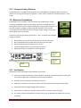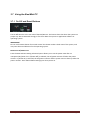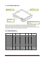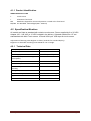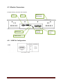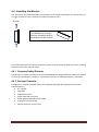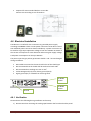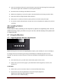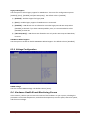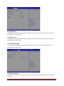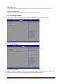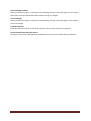
1
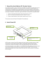
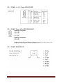
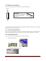
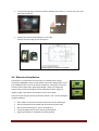
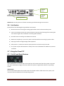
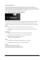
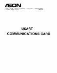
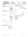
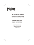
AUTIC SYSTEM MARINE PC Installation and User Manual Autic System Marine PC Rev. 3 January 2015 Disclaimer Only qualified personnel can take care of installing and repairing these products. Autic System AS does not take responsibility for products where the seal is broken by the customer. Claims for errors or omissions with the item must be carried out without undue delay. Autic System AS liability is limited to repair or replacement of the products. Autic System AS is not responsible for replacement costs or other consequential damages. Trademarks Windows 7 and Windows XP are registered trademarks of Microsoft Corporation. Atom N2700 and SGS545 PowerVR are registered trademarks of Intel Corporation. Revisions Rev. No. Date Description Rev. 1 August 2013 Original Rev. 2 March 2014 Corrections and additions have been made on pages 9, 10, 13, 20, 22, 24, 29, 32, 36 and 46-47. Rev. 3 January 2015 Corrections have been made on pages 8, 9, 18, 24, 25, 32, 33, 34, 37 and 39. Addresses Postal address: Box 2099, 3103 Tønsberg, Norway Visiting address: Stoltenbergs gate 48, 3110 Tønsberg, Norway E-mail: Sales: [email protected] Support: [email protected] Telephone: +47 33 30 09 50 Page 2 Rev. 3 Telefax: +47 33 30 09 55 Autic System Marine PC Contents 1 About the Autic Marine PC Product Series ...................................................................................7 2 Autic Panel PC .............................................................................................................................7 2.1 Range of Panel PC products ....................................................................................................8 2.1.1 Product Identification ....................................................................................................8 2.2 Specifications Panel PC ...........................................................................................................8 2.3 Connectors .............................................................................................................................9 2.3.1 COM 2, 4, 5, 6 D-sub 9-Pin RS-232 ............................................................................... 10 2.3.2 COM1 D-sub 9-Pin RS-232/485/422............................................................................. 10 2.3.3 COM3 RJ45 RS-232 ...................................................................................................... 10 2.3.4 Ethernet....................................................................................................................... 11 2.3.5 USB .............................................................................................................................. 11 2.4 Installing the Panel PC .......................................................................................................... 11 2.4.1 Package contents ......................................................................................................... 11 2.5 Mechanical Installation ........................................................................................................ 12 2.5.1 Compass Safety Distance ............................................................................................. 12 2.5.2 Installation Methods .................................................................................................... 12 2.6 Electrical Installation ............................................................................................................ 13 2.6.1 Verification .................................................................................................................. 14 2.7 Using the Panel PC ............................................................................................................... 14 3 2.7.1 On-Off and Reset Buttons ............................................................................................ 14 2.7.2 Monitor Adjustment, High brightness .......................................................................... 15 2.7.3 Monitor Adjustment, Standard Brightness ................................................................... 16 Autic Box PC .............................................................................................................................. 17 3.1 Range of products ................................................................................................................ 18 3.1.1 Product Identification .................................................................................................. 18 3.2 Specifications Box/Mini PC ................................................................................................... 18 3.2.1 Technical data .............................................................................................................. 18 Autic System Marine PC Rev. 3 Page 3 3.3 Connectors ........................................................................................................................... 19 3.3.1 COM2,4,5, 6 D-sub 9-Pin RS-232 .................................................................................. 20 3.3.2 COM1 D-sub 9-Pin RS-232/485/422............................................................................. 20 3.3.3 COM3 RJ45 RS-232 ...................................................................................................... 20 3.3.4 Ethernet....................................................................................................................... 21 3.3.5 USB .............................................................................................................................. 21 3.4 Installing the Box/Mini PC .................................................................................................... 21 3.4.1 Package contents ......................................................................................................... 21 3.5 Mechanical Installation ........................................................................................................ 21 3.5.1 Compass Safety Distance ............................................................................................. 22 3.6 Electrical Installation ............................................................................................................ 22 3.6.1 Verification .................................................................................................................. 22 3.7 Using the Box/Mini PC .......................................................................................................... 23 3.7.1 4 On-Off and Reset Buttons ............................................................................................ 23 Autic Marine Monitors .............................................................................................................. 24 4.1 Range of Products ................................................................................................................ 24 4.1.1 Product Identification .................................................................................................. 25 4.2 Specification Monitors.......................................................................................................... 25 4.2.1 Technical Data ............................................................................................................. 25 4.3 Monitor Connectors ............................................................................................................. 26 4.3.1 USB Pin Configuration .................................................................................................. 26 4.4 Installing the Monitor ........................................................................................................... 27 4.4.1 Compass Safety Distance ............................................................................................. 27 4.4.2 Package Contents......................................................................................................... 27 4.5 Mechanical Installation of the Monitor ................................................................................. 28 4.6 Electrical Installation ............................................................................................................ 29 4.6.1 Verification .................................................................................................................. 29 4.6.2 Installing Options ......................................................................................................... 30 Page 4 Rev. 3 Autic System Marine PC 4.7 Using the Monitors ............................................................................................................... 30 5 4.7.1 High-Brightness Monitor Adjustments ......................................................................... 30 4.7.2 Standard-Brightness Monitor Adjustments .................................................................. 31 Product Dimensions .................................................................................................................. 32 5.1 Panel PC Dimensions ............................................................................................................ 32 5.2 Box/Mini PC Dimension ........................................................................................................ 38 5.3 Monitor Dimensions ............................................................................................................. 38 6 UEFI and Bios Setting ................................................................................................................ 40 6.1 Introduction ......................................................................................................................... 40 6.1.1 UEFI Menu Bar ............................................................................................................. 40 6.1.2 Navigation Keys ........................................................................................................... 41 6.2 Main Screen ......................................................................................................................... 41 6.3 Advanced Screen .................................................................................................................. 42 6.3.1 CPU Configuration........................................................................................................ 43 6.3.2 Chipset Configuration .................................................................................................. 43 6.3.3 Storage Configuration .................................................................................................. 44 6.3.4 Super IO Configuration................................................................................................. 45 6.3.5 Changing from RS232 to RS422/485 ............................................................................. 46 6.3.6 ACPI Configuration ....................................................................................................... 47 6.3.7 USB Configuration ........................................................................................................ 48 6.3.8 Voltage Configuration .................................................................................................. 49 6.4 Hardware Health Event Monitoring Screen ........................................................................... 49 6.5 Boot Screen .......................................................................................................................... 50 6.6 Security Screen..................................................................................................................... 51 6.7 Exit Screen ........................................................................................................................... 51 7 Operating System ...................................................................................................................... 53 7.1 Customer Specified or Trial Version ...................................................................................... 53 7.2 Shutting Down Properly ....................................................................................................... 53 Autic System Marine PC Rev. 3 Page 5 8 Service ...................................................................................................................................... 54 8.1 Return of products to Autic System. ..................................................................................... 54 8.2 Accessories........................................................................................................................... 54 Page 6 Rev. 3 Autic System Marine PC 1 About the Autic Marine PC Product Series Autic System provides a series of Panel PCs, Box/Mini PC and Monitors approved for use in industrial and marine applications. All products got a construction to operate without any moving parts as ventilation fan and hard disk drive. We do give flexibility to select Panel PC with all functions included or Box/Mini PC with external monitor(s). All parts are based on the same base of hardware. Products are approved for Marine use by DNV 2,4 and IEC 60945. 1. Touch-screen Panel PCs with screen sizes from 8,4” to 24” 2. Box PC with identical Motherboard as the Panel PC series. 3. Touch-screen Monitor’s with screen sizes from 8,4” to 24” This manual covers the Panel PC, Box/Mini PC and Monitors. 2 Autic Panel PC Touch screen Front bezel IO and power connectors Membrane keypad for monitor adjustment APPC series is a series Panel PCs designed for Autic System for optimal solution of HMI functionality to marine and industrial markets. Sturdy design based on MIL-specified components. Powerful CPU based on Intel Atom N2700 processor provides maximum performance based on known platform. Intel SGS545 PowerVR graphics processor for quick screen refresh. Multitouch allows screen operation with both hands. The PC provides practical functionality such as easy access to the hard drive and connectors for redundant power supplies. Autic System Marine PC Rev. 3 Page 7 2.1 Range of Panel PC products DNV 2.4 and IEC60945 approved. Display format 4:3 APPC-8427T-AL-FL APPC-10427T-AL-FL APPC-10427T-AL-FLXG APPC-1227T-AL-FL APPC-1227T-AL-FLXG APPC-1527PT-AL-FL APPC-1727PT-AL-FL APPC-1927PT-AL-FL Display format 16:9 APPC-11627T-AL-FL APPC-15627T-AL-FL APPC-2227PT-AL-FL APPC-2427PT-AL-FL Screen size Screen resolution Display brigthness Colors RS-232 RS-232 RS-485 RS-422 USB (2.0) PCI Power consump tion 8” 10.4 ” 10.4 ” 800x600 800x600 1024x768 500 nit LED 300 nit CCFL 300 nit LED 262K 262K 262K 3 5 5 1 1 1 6 6 6 0 0 0 30 W 40 W 40 W 12” 12” 800x600 1024x768 300 nit CCFL 420 nit LED 16.7M 16.7M 5 5 1 1 6 6 0 0 40 W 40 W 15” 17” 19” 1024x768 1280x1024 1280x1024 300 nit CCFL 300 nit CCFL 300 nit CCFL 16.7M 16.7M 16,7M 5 5 5 1 1 1 6 6 6 1 1 1 50 W 60 W 70 W 11,6” 15,6” 22” 24” 1366x768 1920x1080 1920x1080 1920x1080 200 nit LED 300 nit LED 300 nit CCFL 300 nit LED 262K 262K 16.7M 16.7M 2 5 5 5 1 1 1 1 4 6 6 6 0 1 1 1 40 W 50 W 75 W 80 W 2.1.1 Product Identification Product description: APPC-2427PT-AL-FL T P AL FL MK 8N/10N Touch screen PCI slot Aluminum front Bezel Fan-less Membrane keypad for monitor adjustment. Located at the front bezel. Sun readable. LED backlight (800 – 1000 nit) Serial number: 1927T-AMK-10N-DC-SSD60G-1304022-C T AMK 10N DC SSD60G 1304022 C Touch Screen Aluminum bezel with membrane keypad Display brightness. 10N=10 nits, 8N=8 nits, 5N= 5 nits DC power supply built-in 60GB SSD, 250GB HDD etc. 13 = 2013; 04 = April, 022 = 22th unit of this serial number Mechanical version C 2.2 Specifications Panel PC All models are fitted as standard with 4 GB of RAM, 2 LAN ports, mini PCIe slot, resistive touch screen, 120 GB SSD drive. Power supplied by 9 to 32 VDC. Adapter 100 – 240 VAC to 12 VDC included in the delivery. HDMI / VGA output for additional monitor. Page 8 Rev. 3 Autic System Marine PC PCI slot and number of serial ports depend on the size of the Panel PC. Optional equipment Membrane keypad in front for backlight dimming and display adjustment 2 LAN port (Total 4 ports). Sun readable monitor 2 Opto Isolates PCI-slot based serial ports RS-232C or RS-422/485. (DNV approved) Technical Data Front panel protection IP65 Rear panel protection IP22 Power supply +24 VDC (9-32 VDC). Power adapter (Model according to consumption) 100 – 240 VAC to 12 VDC Power consumption 30 to 80 W Ambient temperature. Vertical mounting 0° to +60°C Ambient temperature. Horizontal mounting 0° to +50°C Storage temperature -20°to+80°C Relative humidity 5-85% non-condensing Approvals CE/ FCC/Rohs Marine certification DNV 2.4 and IEC60945 2.3 Connectors COM (RJ45) 4xUSB HDMI COM COM COM MS/KB COM 9-36VDC Power Earthing terminal PCI Slot COM Audio IO 2xLAN 2xUSB VGA ON/OFF and RST button Autic System Marine PC Rev. 3 Page 9 2.3.1 COM 2, 4, 5, 6 D-sub 9-Pin RS-232 2.3.2 COM1 D-sub 9-Pin RS-232/485/422 RS422 pin assignment Pin 1: TX+ Pin 2: RX+ Pin 3: TXPin 4: RXRS485 pin assignment Pin 1: TX+ Pin 3: TXNOTE! Selection of RS232, RS422 or RS485 port is done from Bios setting under Super IO Configuration as described in Chapter 6.3.5. 2.3.3 COM3 RJ45 RS-232 Page 10 Rev. 3 Autic System Marine PC 2.3.4 Ethernet 2.3.5 USB The Panel PC has galvanic isolation against the 24 VDC feed. There is no galvanic isolation between the communication ports for RS-232, RS-422/485 and USB. The Ethernet connection has galvanic isolation. 2.4 Installing the Panel PC 2.4.1 Package contents The Panel PC is shipped in adapted dual layer cardboard packaging with polystyrene protection. Standard delivery: The Panel PC Power cable with connector Power adapter 100 – 240 VAC to 12 VDC Sealing for panel mounting Quik mounting kit CD with drivers for Ethernet and Touch screen When specified, a CD with computer operating system is included Autic System Marine PC Rev. 3 Page 11 2.5 Mechanical Installation Panel PC should be installed in vertical position to prevent overheating. Air flow IMPORTANT! For installation at an angle, the PC must be equipped with a ventilation fan. For product dimensions and cutout dimensions, please refer to Chapter 5. Make the cutout according cutout dimension for the selected model. 2.5.1 Compass Safety Distance The monitor is certified according to DNV 2.4 and IEC60945 for bridge installation. Minimum distance to steering and emergency compass is 1 (one) meter. Distance to standard compass is 1.45 meter. 2.5.2 Installation Methods There are four methods for installation. Quick mounting is standard. Quick mounting fittings. 10 screws with nuts behind front bezel. Page 12 Rev. 3 Autic System Marine PC 4 screws through holes in the front bezel. Suitable when there is no access from rear. This mounting is optional. Prepared for Vesa standard bracket at rear side. Various sizes according to size of Panel PC. Fastening holes in monitor back plate. 2.6 Electrical Installation The Panel PC is certified for the connection to earthed power supply according to EN60950. There are two power connectors allowing the use of two individual power sources to obtain redundancy. One power connector can be used for single input. Operating voltage is from 9 to 36 VDC. Be aware of the current consumption for wire dimension when using low supply voltage. Total power consumption can be up to 80 W. The power input has got polarity protection should + and – be interchanged during installation. Data cables connected to the unit should to be of the shield type. We recommend that the shield shall be earthed on both sides. We recommend using min. 4 mm² earthing wire. Isolate PCB ground (0 V) from chassis ground (earth). Signal ground (0 V) is isolated from chassis ground. Autic System Marine PC Rev. 3 Page 13 9-36VDC Power 9-36VDC Power Earthing terminal NOTE! Make sure the power is off when connecting and disconnecting the connectors. 2.6.1 Verification Please observe the following during installation and startup. 1) Be accurate when mounting the sealing tape between the front bezel and the panel. 2) Cover the ventilation holes with a piece of paper to prevent metal shavings from entering the unit. Remove again after installation to ensure good ventilation. 3) Ground the unit according to installation instruction. 4) Make sure the polarity is correct for power connection before connecting to power outlet. 5) Keep signal cable and high voltage cable separated. 6) After power on, make sure that the system performs a normal startup of the OS. 7) The system may be delivered with a 30 day trial version of Windows OS. Make sure you have a valid OS. 2.7 Using the Panel PC 2.7.1 On-Off and Reset Buttons The On-Off button is at the rear side of the Panel PC. This button shuts down the system in a proper way. We recommend strongly to first shut down the system via application software or operating system. IMPORTANT! Do not use the Reset button for normal restart! This button makes a hard reset of the system, and may cause abnormal behavior for the operating system. Page 14 Rev. 3 Autic System Marine PC Restore on AC/Power Loss From the UEFI and Bios Setting Advanced option allows you to set the power state after an unexpected AC/power loss. If [Power Off] is selected, the AC/power remains off when the power recovers. If [Power On] is selected, the AC/power resumes and the system starts to boot up when the power recovers. Enter UEFI and Bios Setting by F2 when power on. 2.7.2 Monitor Adjustment, High brightness Power indicator and membrane keypad for Panel PC with High Brightness display (Sun readable). For bridge solutions with dimming according to IEC 62288, Sun readable (SR) option must be selected. For operation in other locations on the ship, standard screen brightness can be selected. MENU 1) Press the menu key once, you will see the menu with options on the screen. 2) Under menu, press menu key again, you will be able to select brightness, contrast, and volume, etc. UP & DOWN 1) Under menu, you can use these 2 keys to increase and decrease setting. 2) These buttons are directly dedicated to control the display brightness. 3) Adjustment of Dimming value brighter or darker. (256 levels for Sun readable display.) AUTO 1) Press AUTO key to auto adjust/centralize the picture on the display. 2) Under Menu, AUTO key functions as "exit" to get out of menu. On-Off Switch off the Display part of the Panel PC. The Panel PC is still running when the Display is off. Display ON/OFF function can be disabled from factory. Autic System Marine PC Rev. 3 Page 15 2.7.3 Monitor Adjustment, Standard Brightness Membrane keypad for Panel PC with standard display. These buttons control the speaker volume. These buttons control the display brightness. Adjustment of Dimming value brighter or darker. (16 levels for standard display.) Brightness for this display is not dimmable down to 1 nit as specified in IEC 60945 for use on Bridge Switches off the display part of the Panel PC. The Panel PC is still running when the display is off. Display ON/OFF function can be disabled from factory. Page 16 Rev. 3 Autic System Marine PC 3 Autic Box PC 2x Lan ports 3x COM ports IO and Power connectors PCI slot The AMPC-2700 is a Box (or Mini) PC intended for marine and industrial use. Sturdy design based on MIL-specified components. Powerful CPU based on Intel Atom N2700 processor provides maximum performance based on known platform. Intel SGS545 PowerVR graphics processor for quick screen refresh. The PC is delivered with practical functionality such as easy access to the hard drive and redundant power supply connectors. Autic System Marine PC Rev. 3 Page 17 3.1 Range of products AMPC-2700 LAN RS-232-C RS-232, RS-485, RS-422 USB (2.0) Mini PCIe PCI Power consumption 4 5 1 6 1 1 25 W 3.1.1 Product Identification AMPC-2700 Box/Mini PC. 3.2 Specifications Box/Mini PC As standard fitted with 4 GB of RAM, 4 LAN ports, mini PCIe slot, 120 GB SSD drive. Power supplied by 9 to 32 VDC. Adapter 100 - 240 VAC to 12 VDC included in the delivery. 3.2.1 Technical data IP protection IP22 Power supply +24 VDC (9-32 VDC). Power adapter (Model according to consumption) 110 – 240 VAC to 12 VDC Power consumption 25 W Ambient temperature. Vertical mounting 0° to +60°C Ambient temperature. Horizontal mounting 0° to +50°C Storage temperature -20° to +80°C Relative humidity 5-85% non-condensing Approvals CE/ FCC/Rohs Marine certification DNV 2.4 and IEC60945 Page 18 Rev. 3 Autic System Marine PC 3.3 Connectors COM3 (RJ45) COM (RJ45) COM 2xLAN COM ON/OFF and RST button MS/KB Audio IO 9-36VDC Power Earthing terminal COM 2xUSB PCI Slot VGA 4xUSB HDMI 2xLAN COM Autic System Marine PC Rev. 3 COM COM Page 19 3.3.1 COM2,4,5, 6 D-sub 9-Pin RS-232 3.3.2 COM1 D-sub 9-Pin RS-232/485/422 RS422 pin assignment Pin 1: TX+ Pin 2: RX+ Pin 3: TXPin 4: RXRS485 pin assignment Pin 1: TX+ Pin 3: TXNOTE! Selection of RS232, RS422 or RS485 port is done from Bios setting under Super IO Configuration as described in Chapter 6.3.5. 3.3.3 COM3 RJ45 RS-232 Page 20 Rev. 3 Autic System Marine PC 3.3.4 Ethernet 3.3.5 USB The Box/Mini PC has galvanic isolation against the 24VDC feed. There is no galvanic isolation between the communication ports for RS-232, RS-422/485 and USB. Ethernet connection has galvanic isolation. 3.4 Installing the Box/Mini PC 3.4.1 Package contents The Box/Mini PC is shipped in adapted dual layer cardboard packaging with polystyrene protection. Standard delivery includes: Box/Mini PC Power cable with connector Power adapter 100- 240 VAC to 12 VDC. CD with drivers for Ethernet When specified, computer Operating System is included on CD. 3.5 Mechanical Installation We recommend vertical mounting of the Box/Mini PC for optimal ventilation for the heatsink. For product dimensions, please refer to Chapter 5. Autic System Marine PC Rev. 3 Page 21 3.5.1 Compass Safety Distance The Box/Mini PC is certified according to DNV 2.4 and IEC60945 for bridge installation. Minimum distance to steering and emergency compass is 1 (one) meter. Distance to standard compass is 1,45 meter. 3.6 Electrical Installation The Box/Mini PC is certified for the connection to grounded power supply according to EN60950. There are two power connectors enabling the use of two separate power sources to obtain redundancy. Single power connector can be used. Operation voltage is from 9 to 36 VDC. Be aware of the current consumption for wire dimension when using low supply voltage. Total power consumption can be up to 80 W. The power input has got polarity protection if + and – should be interchanged during installation. Data cables connected to the unit should to be of the shield type. We recommend that the shield shall be earthed on both sides. We recommend using earthing wire min. 4 mm². Isolate PCB ground (0 V) from chassis ground (earth). Signal ground (0 V) is isolated from chassis ground. 9-36 VDC Power 9-36 VDC Power Earth 3.6.1 Verification Please observe the following during installation and startup. 1) Cover the ventilation holes with a piece of paper to prevent metal shavings from entering the unit. Remove again after installation to ensure good ventilation. 2) Ground the unit according to installation instruction. 3) Make sure the polarity is correct for power connection before connecting to power outlet. 4) Keep signal cable and high voltage cable separated. 5) After power on, make sure that the system performs a normal startup of the OS. 6) The system may be delivered with a 30 day trial version of Windows OS. Make sure you have a valid OS. Page 22 Rev. 3 Autic System Marine PC 3.7 Using the Box/Mini PC 3.7.1 On-Off and Reset Buttons The On-Off switch is at the rear side of the Box/Mini PC. This button does shut down the system in a proper way. We recommend strongly to first shut down the system via application software or operating system. IMPORTANT! Do not use the Reset button for normal restart! This button makes a hard reset of the system, and may cause abnormal behavior for the operating system. Restore on AC/Power Loss From the UEFI and Bios Setting Advanced option allows you to set the power state after an unexpected AC/power loss. If [Power Off] is selected, the AC/power remains off when the power recovers. If [Power On] is selected, the AC/power resumes and the system starts to boot up when the power recovers. Enter UEFI and Bios Setting by F2 when power on. Autic System Marine PC Rev. 3 Page 23 4 Autic Marine Monitors Front bezel Touch screen IO and power connectors Membrane keypad for monitor adjustment AMON is a series of monitors designed for Autic System for optimal solution of HMI functionality to marine and industrial markets. Sturdy design based on MIL-specified components. Multitouch allows screen operation with both hands. Monitors are delivered with practical functionality such as redundant power connections. 4.1 Range of Products DNV 2.4 and IEC60945 approved. Display format 4:3 AMON-84T-AL AMON-104T-AL AMON-104T-AL-XG AMON-120T-AL AMON-120T-AL-XG AMON-150PT-AL AMON-170PT-AL AMON-190PT-AL Display format 16:9 AMON-116T-AL AMON-156T-AL AMON-220PT-AL AMON-240PT-AL Page 24 Display size Display Resolution Brigthness Colors Touch Power Consumption 8,4” 10,4 ” 10,4 ” 12” 12” 15” 17” 19” 800x600 800x600 1024x768 800x600 1024x768 1024x768 1280x1024 1280x1024 500 nit LED 300 nit CCFL 300 nit LED 300 nit CCFL 320o nit CCFL 300 nit CCFL 300 nit CCFL 300 nit CCFL 262K 262K 262K 16.7M 16.7M 16.7M 16.7M 16.7M Single Single Single Single Single Multi Multi Multi 10 W 15 W 15 W 25 W 25 W 30 W 30 W 50 W 11,6” 15,6” 21,5” 23,6” 1366x768 1920x1080 1920x1080 1920x1080 200 nit LED 300 nit LED 300 nit CCFL 300 nit LED 262K 262K 16.7M 16.7M Single Single Multi Multi 25 W 30 W 50 W 55 W Rev. 3 Autic System Marine PC 4.1.1 Product Identification AMON-2427PT-AL-FL-MK T L MK 8N/10N Touch Screen Aluminium front bezel Membrane keypad for monitor adjustment. Located at the front bezel. Sun Readable. LED backligth (800 – 1000 nit) 4.2 Specification Monitors All models are fitted as standard with resistive touch screen. Power supplied by 9 to 32 VDC. Adapter 100 – 240 VAC to 12 VDC included in the delivery. Selected models from 15" are standardized with Multi Touch screen. VDI and VGA input. USB input for touch screen. Adjustment of dimming value brighter or darker (16 levels for standard display). Brightness is dimmable according to IEC 60945 for use on bridge. 4.2.1 Technical Data Front panel protection IP65 Rear panel protection IP22 Power supply +24 VDC (9-32VDC). Power adapter (Model according to consumption) 100 – 240 VAC to 12 VDC Power consumption 10 to 55 W Ambient temperature. Vertical mounting 0° to +60°C Ambient temperature. Horizontal mounting 0° to +50°C Storage temperature -20° to +80°C Relative humidity 5 - 85% non-condensing Approvals CE/ FCC/Rohs Marine certification DNV 2.4 and IEC60945 Autic System Marine PC Rev. 3 Page 25 4.3 Monitor Connectors Example drawing. Variation due to Model VGA ON/OFF and Reset button VDI Earthing terminal Audio input 9-36VDC Power USB for Touch 4.3.1 USB Pin Configuration Page 26 Rev. 3 Autic System Marine PC 4.4 Installing the Monitor The monitor can be installed vertically, horizontally or at an angle. If installing at an horizontally or at an angle, make sure there is sufficient ventilation around the unit! Air flow IMPORTANT! For installation at an angle, sufficient ventilation must be provided around the monitor. For product dimensions and cutout dimensions, please refer to Chapter 5. Make the cutout according to dimensions for the selected model. 4.4.1 Compass Safety Distance The Monitor is certified according to DNV 2.4 and IEC60945 for bridge installation. Minimum distance to steering and emergency compass is 1 (one) meter. Distance to standard compass is 1,45 meter. 4.4.2 Package Contents The Monitor is shipped in adapted dual layer cardboard packaging with polystyrene protection. Standard delivery: The monitor VGA cable USB cable for touch Power cable with connector Power adapter 100/200 VAC to 12VDC Sealing for panel mounting CD with drivers for touch screen Autic System Marine PC Rev. 3 Page 27 4.5 Mechanical Installation of the Monitor Make the cutout according cutout dimension for the selected model. There are four methods for installation. Quick mounting is the standard method. Quick mounting fittings 10 screws with nuts behind front bezel. 4 screws through holes in the front bezel. Suitable when there is no access from rear. This mounting is optional. Page 28 Rev. 3 Autic System Marine PC Prepared for Vesa standard bracket at rear side. Various sizes according to size of Panel PC. 4.6 Electrical Installation The Monitor is certified for the connection to grounded power supply according to EN60950. There are two power connectors to be able to use of two individual power sources to obtain redundancy. 1 power connector can be used for single input. Operation Voltage is from 9 to 36 VDC. Be aware of the current consumption for wire dimension when using low supply voltage. Total power consumption can be up to 80 watt. The power input has got polarity protection should + and – be interchanged during installation. Data cables connected to the unit should to be of the shield type. We recommend that the shield shall be earthed on both sides. We recommend use eathing wire min. 4 mm². Isolate PCB ground (0 V) from chassis ground (earth). Signal ground (0 V) is isolated from chassis ground. 9-36VDC Power 9-36VDC Power Ground 4.6.1 Verification Please observe the following during installation and startup. 1) Be accurate when mounting the sealing tape between the front bezel and the panel. Autic System Marine PC Rev. 3 Page 29 2) Cover the ventilation holes with a piece of paper to prevent metal shavings from entering the unit. Remove again after installation to ensure good ventilation. 3) Ground the unit according to installation instruction. 4) Make sure the polarity is correct for power connection before connecting to power outlet. 5) Keep signal cable and high voltage cable separated. 6) After power on, make sure that the system performs a normal startup of the OS. 7) The system may be delivered with a 30 day trial version of Windows OS. Make sure you have a valid OS. 4.6.2 Installing Options IMPORTANT! Please observe that by installing in the computer any options not supplied by Autic, such as additional memory chips, you will do so at your own risk, and the warranty of the product will no longer be valid. 4.7 Using the Monitors 4.7.1 High-Brightness Monitor Adjustments Membrane keypad on monitors with High Brightness display. (Sun readable, for use on the bridge.) For bridge solutions with dimming according to IEC 62288, Sun readable (SR) option must be selected. For operation in other locations on the ship, standard screen brightness can be selected. MENU 1) Press menu key once, you will see the menu with options on the screen. 2) Under menu, press menu key again, you will be able to select brightness, contrast, and volume, etc. UP & DOWN 1) Under menu, you can use these 2 keys to increase and decrease setting. 2) These buttons are directly dedicated to control the display brightness. Adjustment of dimming value brighter or darker. (256 levels for Sun readable display) Page 30 Rev. 3 Autic System Marine PC AUTO 1) Press AUTO key to auto adjust/centralize the picture on the display. 2) Under menu, AUTO key functions as "exit" to leave the menu. ON/OFF Switch off the high-brightness monitor. Note that the monitor ON/OFF function can be disabled from factory. This must be specified when ordering the monitor. 4.7.2 Standard-Brightness Monitor Adjustments Membrane keypad for monitors with standard display (for use in engine room or similar). These buttons adjust the speaker volume. These buttons control the display brightness. Adjustment of dimming value brighter or darker. (16 levels for standard display) Brightness for this display is not dimmable down to 1 nit as specified in IEC 60945 for use on bridge. Switch off the standard-brightness monitor. Note that the monitor ON/OFF function can be disabled from factory. This must be specified when ordering the monitor. Autic System Marine PC Rev. 3 Page 31 5 Product Dimensions 5.1 Panel PC Dimensions L D T A H B Front Frame Dept h Cutout (Cutout dimension are product dimensions plus 3 mm.) Product dimensions in mm Cutout L H D T Weight A B APPC-8427T-AL-FL 255 224 97 6 3 kg 237 207 APPC-10427T-AL-FL 305 260 90 6 4 kg 287 243 APPC-10427T-AL-FL-XGA 305 260 90 6 4 kg 287 243 APPC-1227T-AL-FL 333 285 89 6 5 kg 316 268 APPC-1227T-AL-FL-XGA 333 285 89 6 5 kg 316 268 APPC-1527PT-AL-FL 395 325 76 6 6 kg 378 309 APPC-1727PT-AL-FL 418 368 79 8 7 kg 401 351 APPC-1927PT-AL-FL 454 392 80 8 8 kg 433 375 APPC-11627T-AL-FL 345 252 86 6 5 kg 328 235 APPC-15627T-AL-FL 415 280 71 6 6 kg 398 263 APPC-2227PT-AL-FL 550 360 78 8 9 kg 533 343 APPC-2427PT-AL-FL 600 380 77 6 10 kg 582 363 4:3 models 16:9 models Page 32 Rev. 3 Autic System Marine PC Panel PC 4:3 models APPC-8427T-AL-FL APPC-10427T-AL-FL / APPC-10427T-AL-FL-XG Autic System Marine PC Rev. 3 Page 33 APPC-1227T-AL-FL / APPC-1227T-AL-FL-XG APPC-1527PT-AL-FL Page 34 Rev. 3 Autic System Marine PC APPC-1727PT-AL-FL APPC-1927PT-AL-FL Autic System Marine PC Rev. 3 Page 35 Panel PC 16:9 models APPC-11627T-AL-FL APPC-15627T-AL-FL Page 36 Rev. 3 Autic System Marine PC APPC-2227PT-AL-FL APPC-2427PT-AL-FL Autic System Marine PC Rev. 3 Page 37 5.2 Box/Mini PC Dimension AMPC-2700 5.3 Monitor Dimensions L D T A H Front Frame B Dept h Cutout Monitors have the same physical dimension as the Panel PC models except the depth (D) of the product. D Page 38 Rev. 3 Autic System Marine PC (Cutout dimension are product dimensions plus 3 mm.) Product dimensions in mm Cutout L H D T Weight A B AMON-84T-AL 255 224 70 6 2 kg 237 207 AMON-104T-AL 305 260 73 6 3 kg 287 243 AMON-104T-AL-XG 305 260 73 6 3 kg 287 243 AMON-120T-AL 333 285 72 6 4 kg 316 268 AMON-120T-AL-XG 333 285 72 6 4 kg 316 268 AMON-150T-AL 395 325 76 6 5 kg 378 309 AMON-170T-AL 418 368 77 8 6 kg 401 351 AMON-190T-AL 454 392 78 8 8 kg 433 375 AMON-116T-AL 345 252 68 6 4 kg 328 235 AMON-156T-AL 415 280 65 6 5 kg 398 263 AMON-220T-AL 550 360 78 8 8.5 kg 533 343 AMON-240T-AL 600 380 64 8 9.5 kg 582 363 4:3 models 16:9 models Autic System Marine PC Rev. 3 Page 39 6 UEFI and Bios Setting 6.1 Introduction This section explains how to use the UEFI SETUP UTILITY to configure your system. The UEFI chip on the motherboard stores the UEFI SETUP UTILITY. You may run the UEFI SETUP UTILITY when you start up the computer. 1) Please press <F2> or <Del> during the Power-On-Self-Test (POST) to enter the UEFI SETUP UTILITY, otherwise, POST will continue with its test routines. 2) If you wish to enter the UEFI SETUP UTILITY after POST, restart the system by pressing <Ctl> + <Alt> + <Delete>, or by pressing the reset button on the system chassis. 3) You may also restart by turning the system off and then back on. WARNING! Because the UEFI software is constantly being updated, the following UEFI setup screens and descriptions are for reference purpose only, and they may not exactly match what you see on your screen. 6.1.1 UEFI Menu Bar The top of the screen has a menu bar with the following selections: Main To set up the system time/date information OC Tweaker To set up overclocking features Advanced To set up the advanced UEFI features H/W Monitor To display current hardware status Boot To set up the default system device to locate and load the Operating System Security To set up the security features Exit To exit the current screen or the UEFI SETUP UTILITY Use < > key or <> key to choose among the selections on the menu bar, and then press <Enter> to get into the sub screen. You can also use the mouse to click your required item. Page 40 Rev. 3 Autic System Marine PC 6.1.2 Navigation Keys Please check the following table for the function description of each navigation key. Navigation Key(s) Function Description / Moves cursor left or right to select Screens / Moves cursor up or down to select items +/- To change option for the selected items <F1> To display the General Help Screen <F7> Discard changes <F9> To load optimal default values for all the settings <F10> To save changes and exit the UEFI SETUP UTILITY <F12> Print screen <ESC> To jump to the Exit Screen or exit the current screen 6.2 Main Screen When you enter the UEFI SETUP UTILITY, the Main screen will appear and display the system overview. Autic System Marine PC Rev. 3 Page 41 6.3 Advanced Screen In this section, you may set the configurations for the following items: CPU Configuration, Chipset Configuration, Storage Configuration, Super IO Configuration, ACPI Configuration, USB Configuration and Voltage Configuration. WARNING! Setting wrong values in this section may cause the system to malfunction. Instant Flash Instant Flash is a UEFI flash utility embedded in Flash ROM. This convenient UEFI update tool allows you to update system UEFI without entering operating systems first like MS-DOS or Windows®. Just launch this tool and save the new UEFI file to your USB flash drive, floppy disk or hard drive, then you can update your UEFI only in a few clicks without preparing an additional floppy diskette or other complicated flash utility. Please be noted that the USB flash drive or hard drive must use FAT32/16/12 file system. If you execute Instant Flash utility, the utility will show the UEFI files and their respective information. Select the proper UEFI file to update your UEFI, and reboot your system after UEFI update process completes. Page 42 Rev. 3 Autic System Marine PC 6.3.1 CPU Configuration Intel Hyper Threading Technology To enable this feature, it requires a computer system with an Intel processor that supports HyperThreading technology and an operating system that includes optimization for this technology, such as Windows 7. Set to [Enabled] if using Windows 7. No-Execute Memory Protection No-Execution (NX) Memory Protection Technology is an enhancement to the IA-32 Intel Architecture. An IA-32 processor with “No Execute (NX) Memory Protection” can prevent data pages from being used by malicious software to execute code. 6.3.2 Chipset Configuration Set Panel Type by Use this to configure Set Panel Type. The default value is [UEFI Setup]. Autic System Marine PC Rev. 3 Page 43 Panel Type Selection Use this to select panel type. The default value is [1366x768/18-bit/1-ch/ LED]. ACPI HPET Table Use this item to enable or disable ACPI HPET Table. The default value is [Enabled]. Please set this option to [Enabled] if you plan to use this motherboard to submit Windows® certification. Restore on AC/Power Loss This allows you to set the power state after an unexpected AC/power loss. If [Power Off] is selected, the AC/power remains off when the power recovers. If [Power On] is selected, the AC/power resumes and the system starts to boot up when the power recovers. Onboard HD Audio Select [Auto], [Enabled] or [Disabled] for the onboard HD Audio feature. If you select [Auto], the onboard HD Audio will be disabled when PCI Sound Card is plugged. Front Panel Select [Auto] or [Disabled] for the onboard HD Audio Front Panel. Onboard LAN1 This allows you to enable or disable the “Onboard LAN1” feature. Onboard LAN2 This allows you to enable or disable the “Onboard LAN2” feature. 6.3.3 Storage Configuration Onboard SATAII Mode Use this to select SATA2 mode. Configuration options: [IDE Mode], [AHCI Mode] and [Disabled]. The default value is [IDE Mode]. Page 44 Rev. 3 Autic System Marine PC WARNING! AHCI (Advanced Host Controller Interface) supports NCQ and other new features that will improve SATA disk performance but IDE mode does not have these advantages. Hard Disk S.M.A.R.T. Use this item to enable or disable the S.M.A.R.T. (Self-Monitoring, Analysis, and Reporting Technology) feature. Configuration options: [Disabled] and [Enabled]. Onboard CF This allows users to enable/disable the onboard IDE controller for CF. The default value is [Enabled]. 6.3.4 Super IO Configuration COM1 Configuration Use this to set parameters of COM1. COM2 Configuration Use this to set parameters of COM2. COM3 Configuration Use this to set parameters of COM3. COM4 Configuration Use this to set parameters of COM4. COM5 Configuration Use this to set parameters of COM5. COM6 Configuration Use this to set parameters of COM6. Autic System Marine PC Rev. 3 Page 45 LPT1 Port Configuration Use this set parameters of the onboard parallel port. WDT Timeout Reset This allows users to enable/disable the Watch Dog Timer timeout to reset system. The default value is [Disabled]. 6.3.5 Changing from RS232 to RS422/485 1) Connect a keyboard to the Panel PC or Mini PC. 2) Power on the Panel PC/Mini PC and press F2 to enter BIOS. 3) Select Advanced of main items, and you will see the picture below. Then, select Super IO Configuration and press Enter. 4) Select COM1 Configuration. 5) Move down to Type Select and press Enter. Page 46 Rev. 3 Autic System Marine PC 6) Select the type you want and press Enter. 7) Press F10 and Save. 6.3.6 ACPI Configuration Autic System Marine PC Rev. 3 Page 47 Suspend to RAM Use this item to select whether to auto-detect or disable the Suspend-to- RAM feature. Select [Auto] will enable this feature if the OS supports it. S3 Video Repost Use this to enable/disable S3 Video Repost. The default value is [Enabled]. PS/2 Keyboard Power On Use this item to enable or disable PS/2 keyboard to turn on the system from the power-soft-off mode. PCI Devices Power On Use this item to enable or disable PCI devices to turn on the system from the power-soft-off mode. Ring-In Power On Use this item to enable or disable Ring-In signals to turn on the system from the power-soft-off mode. RTC Alarm Power On Use this item to enable or disable RTC (Real Time Clock) to power on the system. USB Keyboard/Remote Power On Use this item to enable or disable USB Keyboard/Remote to power on the system. USB Mouse Power On Use this item to enable or disable USB Mouse to power on the system. 6.3.7 USB Configuration USB 2.0 Controller Use this item to enable or disable the use of USB 2.0 controller. Page 48 Rev. 3 Autic System Marine PC Legacy USB Support Use this option to select legacy support for USB devices. There are four configuration options: [Enabled], [Auto], [Disabled] and [UEFI Setup Only]. The default value is [Enabled]. 1) [Enabled] – Enables support for legacy USB. 2) [Auto] – Enables legacy support if USB devices are connected. 3) [Disabled] – USB devices are not allowed to use under legacy OS and UEFI setup when [Disabled] is selected. If you have USB compatibility issue, it is recommended to select [Disabled] to enter OS. 4) [UEFI Setup Only] – USB devices are allowed to use only under UEFI setup and Windows / Linux OS. USB Mouse Wheel Support Use this option to enable or disable USB Mouse Wheel Support. The default value is [Disabled]. 6.3.8 Voltage Configuration DRAM Voltage Use this to select DRAM Voltage. The default value is [Auto]. 6.4 Hardware Health Event Monitoring Screen In this section, it allows you to monitor the status of the hardware on your system, including the parameters of the CPU temperature, motherboard temperature, CPU fan speed, chassis fan speed, and the critical voltage. Autic System Marine PC Rev. 3 Page 49 CPU_FAN1 Setting This allows you to set CPU_FAN1’s speed. Configuration options: [Full On] and [Automatic Mode]. The default value is [Full On]. CHA_FAN1 Setting This allows you to set CHA_FAN1’s speed. Configuration options: [Full On] and [Automatic Mode]. The default value is [Full On]. 6.5 Boot Screen In this section, it will display the available devices on your system for you to configure the boot settings and the boot priority. Setup Prompt Timeout This shows the number of seconds to wait for setup activation key. 65535(0XFFFF) means indefinite waiting. Page 50 Rev. 3 Autic System Marine PC Bootup Num-Lock If this item is set to [On], it will automatically activate the Numeric Lock function after boot-up. Boot From Onboard LAN Use this item to enable or disable the Boot From Onboard LAN feature. 6.6 Security Screen In this section, you may set, change or clear the supervisor/user password for the system. 6.7 Exit Screen Save Changes and Exit When you select this option, it will pop-out the following message, “Save configuration changes and exit setup?” Select [OK] to save the changes and exit the UEFI SETUP UTILITY. Autic System Marine PC Rev. 3 Page 51 Discard Changes and Exit When you select this option, it will pop-out the following message, “Discard changes and exit setup?” Select [OK] to exit the UEFI SETUP UTILITY without saving any changes. Discard Changes When you select this option, it will pop-out the following message, “Discard changes?” Select [OK] to discard all changes. Load UEFI Defaults Load UEFI default values for all the setup questions. F9 key can be used for this operation. Launch EFI Shell from filesystem device Attempts to Launch EFI Shell application (Shell64.efi) from one of the available filesystem devices. Page 52 Rev. 3 Autic System Marine PC 7 Operating System 7.1 Customer Specified or Trial Version The computer can be delivered with a customer specified operating system installed. Our standard operating systems are Windows 7, Windows XP or Linux. If no operating system is specified when ordering, a 30-day trial version of Windows 7 is installed. IMPORTANT! Please note that the trial version of Windows 7 stops working after 30 days of operation! 7.2 Shutting Down Properly Shut down the computer in a proper way. If not, the operating system or application software may get interrupted and lose data. Do not switch the power supplies off to shut down the computer, follow the proper shut-down procedure from the operating system. Autic System Marine PC Rev. 3 Page 53 8 Service All service for these products must be done by Autic System AS. 8.1 Return of products to Autic System. Return equipment for service by registering the products via RMA registration at www.autic.no / Support / Returskjema (Return Form). 8.2 Accessories Part name Illustration Comment Power Adapter Specify product Id when ordering. Quick Mounting Kit Set of 10 pcs. Power Connector Set of 2 pcs.. USB Touch Cable For monitor to Box/Mini PC Audio Cable For monitor to Box/Mini PC Page 54 Rev. 3 Autic System Marine PC Autic System Marine PC Rev. 3 January 2015