1
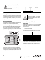
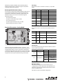
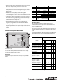
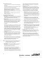
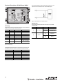
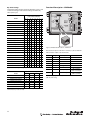
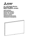
Installation Instructions 45MLA Controller IMPORTANT: SAVE THESE INSTRUCTIONS FOR FUTURE USE. Description The Allen-Bradley 45MLA light array controller drives the photoelectric elements in the light arrays, which are essentially a series of transmitted beam pairs. Five versions of the controller are available, each offering a different communications platform that can be selected to function with a range of PLCs. • 45MLA controller analog model Cat. No. 45MLA-CTRL-ALG • 45MLA controller basic model Cat. No. 45MLA-CTRL-BSC • 45MLA controller I/O model Cat. No. 45MLA-CTRL • 45MLA controller RS485 Cat. No. 45MLA-CTRL-485 Specifications Environmental Certifications cULus and CE Marked for all applicable directives Operating Environment Housing IP54, terminal strip IP20 Operating Temperature [C (F)] 0…+55° (+32…+131°) Storage Temperature [C (F)] -25…+70° (-13…+158°) Relative Humidity 15…95% Optical LED Indicators • 45MLA controller CAN Cat. No. 45MLA-CTRL-CAN The controller includes numerous application features, allowing for customization to the many applications. For instance, the I/O module can be used to configure up to four separate sensing zones with independent outputs and overhang/over-height detection. The basic model has a single on/off output for use in discrete applications. The analog output model offers either a 4…20 mA current or 0…10V output proportional to target height, width, or position. The network communication models (RS485 and CAN) can be used to communicate precise height readings and individual beam status. Features • External controller for 45MLA measuring light arrays Alignment, target present, outputs, inputs, power Electrical Voltage 24V DC ±15% (20.4…27.6V) max. ripple = 5% Current Consumption <300 mA with max. no. of beams to controller, outputs not connected Sensor Protection EN 61000-4-2, EN 61000-4-4 and EN 61000-4-5; short circuit (SCP), reverse polarity and overload Outputs Response Time See the Response Time section on the next page Output Type NPN and PNP (push-pull output) Output Mode Dark operate (when connected as PNP) Output Current 150 mA max. each Input Type Sinking or sourcing (jumper selectable, default is for connection to PNP output) • Height measuring capability Mechanical • Fast reaction time and measurement speed Housing Material ABS (FR) UL94-V0 • Configurable over-height and overhang outputs Cover Material Polycarbonate Connection Types Spring loaded removable terminal strips; 2 x RJ45 (connection to light arrays only); CAN model only: 2 additional RJ45 connectors for CAN comms • Analog model offers either 4…20 mA or 0…10V output proportional to target height, width, or position • Basic models offers single discrete output for use in on/off applications • I/O model features teach button for setting up four height “zones” with individual outputs Accessories Required Accessories 45MLA light arrays (Cat. No. 45MLA-xxxxx0Pxx) • RS485 and CAN communication models provide extra functionality, including: - Connection to RS485 or CAN networks (by model) - Detailed height information - Individual beam status ATTENTION These devices are intended for object recognition only and may not be used for protection of humans (access protection). ATTENTION The cables must be mounted using the provided grommets in order to maintain IP54 standards. Do not allow the cables to be pinched or mechanically stressed in the mounted environment. IMPORTANT For use in NFPA 79 applications only. Pin Signal 1 0V DC Description Power 2 +24V DC Power 3 Ground Ground 4 Not connected Not connected 5 In 2 6 In 1 7 Out 2 8 Out 1 Model specific descriptions Table 1: Controller Terminal Connector Pin Allocation Mounting Instructions This unit can be mounted on a DIN rail either using the mounting brackets on the back or four screws through the holes on the tabs extending from the corners of the housing. In order to reduce the influences of electromagnetic disturbances, ensure that none of the connecting cables are lying next to high power or high frequency circuit cables. Electrical Configuration The controller unit contains a main PCB that controls light array electronics, as well as an extension PCB for additional I/O or communication functionality (model dependent). The emitter and receiver light arrays must be connected to the controller through their respective RJ45 connectors on the main PCB. The grommets (provided) should be installed in the gaps on the side of the controller around the electrical cables. After connecting the cable and placing the grommets, mount the clear plastic cover using the screws provided. ATTENTION The ground connection of the 45 MLA and controller systems can be made either at the light arrays or the controller. Do not ground both the arrays and the controller as that may create ground loops. Functional Description All Models Response Time The measurement or response time (T) can be roughly calculated from the number of beams (n), the scan time per beam (tS) and the analysis time (tA): T = tA + n x tS n = number of optical beams For tS and tA the following approximate values can be assumed: tA (ms) ± 5% tS (ms) ± 5% 45MLA-CTRL-ALG single scan mode (default) 4.1 0.13 45MLA-CTRL-ALG double scan mode 4.1 0.25 45MLA-CTRL-BSC single scan mode (default) 0.6 0.14 45MLA-CTRL-BSC double scan mode 0.8 0.25 45MLA-CTRL 5.3 0.275 45MLA-CTRL-485 2.1 0.275 45MLA-CTRL-CAN 1.0 0.275 S1 Model RJ45 Connector Emitter D2 LED D1 LED Model Specific Extension PCB RJ45 Connector Receiver D3 LED Out 1 D4 LED Out 2 D6 LED In 2 D5 LED In 1 PNP J14 NPN PNP D7 LED - Power NPN Removable In 1 Input Spring-Loaded Connector Logic Jumpers In 2 J2 Pot 2 Pot 1 Out 1 Out 2 In 1 In 2 n. c. Earth. 24 VDC 0 VDC Gaps for cables Figure 1: Controller This main board has two digital inputs and two digital outputs as well as power connections on the terminal connector. The pin descriptions for this connector are listed in Table 1. Any additional connections to be made to the extension PCB are detailed in the model specific sections of this document. 2 Table 2: Response Time Details Double-scan mode can be set with the DIP switches on these models. For example, for a 600 mm array with a 10 mm beam spacing utilizing the I/O model controller, the response time is calculated as follows: T = 5.3 + 60 x 0.275 = 21.8 ms Input Logic LED Indicators The controller inputs are capable of accepting either NPN or PNP outputs. The default setting is configured as a sinking input to connect to a PNP sourcing output. In order to connect the input to an NPN output the jumpers In1 and In2, on the main PCB, must be adjusted as described in Table 3 and Figure 2. The following table indicates the status and description for each LED on the controller’s main PCB. Jumper Connect to PNP Output (Default) Connect to NPN Output In1 Input IN1 active 'high' (+24V) Input IN1 active 'low' (0V) In2 Input IN2 active 'high' (+24V) Input IN2 active 'low' (0V) LED D1 Description Color Meaning Off Target present or light arrays not aligned Green Target not present and light arrays aligned Green flashing Low margin/light intensity inadequate Off Target not present Red Target present Red Flashing System Off Output 1 inactive Light Array OK Table 3: Input Logic as Described by Jumper Settings 24V D2 Light array status 4k3 Input D3 NPN Out1 Green Output 1 active Off Output 2 inactive PNP D4 4k3 Out2 D5 In1 D6 In2 D7 Power Figure 2: Input Logic Sinking/Sourcing Is Defined by the Jumper Setting Output Logic The 45MLA controller uses push-pull outputs that can be connected to either sinking or sourcing input cards. Additionally, the output logic can be inverted using DIP switch S1:5. The procedure to do this is detailed in the sections describing each controller. Green Output 2 active Off Input 1 inactive Green Input 1 active Off Input 2 inactive Green Input 2 active Off Power off Green Power on Table 4: Controller Main Board LED Status DIP Switches DIP switch settings and descriptions are detailed in modelspecific sections in this document. Change DIP switch settings only when the controller power is off. Potentiometer Settings The time settings of outputs Out1 and Out2, overhang duration (t_ot) and minimum output duration (t_out), can be adjusted using the corresponding potentiometers, as described by the following table. Pot Description Direction Limit Value Allowed overhand detection or scan interruption ignore time Counterclockwise t_ot = 0 s Pot 1 Clockwise t_ot = 3.3s Counterclockwise t_out = 0s Clockwise t_out = 3.3s Pot2 Minimum output duration Table 5: Controller Main PCB Potentiometer Adjustments I/O, RS485 and CAN controllers. Basic controller (only when double-scan mode is selected, for example, via DIP switch 4). Potentiometer 1 is not used on the analog controller model. 3 Additionally, the CAN and RS485 controller models offer the flexibility of adjusting these settings through use of specified commands over the serial interface. Resetting Default Parameter Settings All controllers are shipped with default parameter values, that can be changed through the teach process for the I/O model and through serial commands for the RS485 and CAN models. The default parameters can be reset in all models through the following procedure: • Turn controller power off. • Set switch 8 on DIP switch array S1 to ON. Pin Listings The allocation of pins on the main connector, J2, is specified below. Pin Signal Description Remarks 1 0V DC Power — 2 +24V DC Power — 3 Ground Ground — 4 Not connected Not connected — 5 In 2 Not used 6 In 1 7 8 Not used DIP switch S1 (3) = 0 Remote teach DIP switch S1 (3) = 1 Out 2 Error 0V DC = error 24V DC = no error Out 1 Light array interrupted 0V DC = interrupted 24V DC = not interrupted • Turn controller power on. • Set switch eight on DIP switch array S1 to OFF. • Default settings should now be restored. Table 6: J2 Pin Listings S1 Functional Description—Analog Model RJ45 Connector Emitter Analog Teach Extension PushPCB Button D2 LED D1 LED Pin Signal Minimum Maximum 1 I Out 4 mA 20 mA 2 0V DC 3 V Out 0V 10V 4 0V DC RJ45 Connector Receiver D15 LED D13 LED D12 LED D11 LED D10 LED The allocation of pins on the I/O extension PCB is described below. D3 LED Out 1 D4 LED Out 2 D6 LED In 2 D5 LED In 1 J15 D16 LED PNP In 1 NPN PNP D7 LED - Power In 2 NPN Removable Spring-Loaded Connector Input Logic Jumpers Pot 2 Pot 1 Out 1 Out 2 In 1 In 2 n. c. Earth. 24 VDC 0 VDC J2 Table 7: J15 Pin Listings Figure 3: Analog Model The analog controller model offers either 4…20 mA or 0…10V (current or voltage selectable via DIP switch) output proportional to target height, width, or position. The output is automatically scaled to the length of the connected arrays, so most applications do not require additional adjustments. A teach button is available for applications that require customized scaling of the output. LED Indicators The following table describes LED status for LEDs D15 and D16 present on the extension PCB. LED D15 D16 Description Teach Indicator Analog Output Status Status Meaning Off Teach inactive Flashing Teach active Orange Last step of teach process Off V_out = OFF (0V) Flashing Start up (ignore output), over current, or error Green Brightness proportional to analog output Table 8: Analog Board LED Descriptions DIP Switch Settings DIP switches 1 through 6 on the S1 DIP switch array are configured for the various applications described below. If no information is otherwise provided these DIP switches should remain in the OFF position. DIP switch 8 is used to reset default configuration. 4 Note: Once changed, DIP switch settings are only recognized after a power cycle. ATTENTION The following table details DIP switch settings for the I/O board. Please refer to the user manual for further information on the listed functions. Analog—DIP Switch Settings DIP Switch S1 (0: OFF, 1: ON, X: not relevant) 8 7 6 5 4 3 2 1 Default setting Function 0 0 0 0 0 0 0 0 Current output x x x x x x x 0 Voltage output x x x x x x x 1 Absolute mode (position) x x x x x x 0 x Relative mode (size) x x x x x x 1 x Enable remote teach 0 x x x x 1 x x Enable double scan filter 0 x x x 1 x x x Output logic Light Operate = 24V (PNP L.O.) Dark Operate = 0 V (NPN D.O.) 0 x x 0 x x x x Output logic Light Operate = 0 V (NPN L.O.) Dark Operate = 24 V (PNP D.O.) 0 x x 1 x x x x Standard beam counting direction 0 x 0 x x x x x Reverse beam counting direction 0 x 1 x x x x x Normal operation 0 x x x x x x x Set default 1 x x x x x x x Protect the controller from ESD with proper grounding or shunting and the use of static control packaging and materials handling products. Dissipate and neutralize by grounding, ionization, and the use of conductive and dissipative static control materials. The teach button on the extension PCB and the remote teach input (Input 1) both utilize the same teach procedure. Set DIP switch S1:3 to ON (and cycling power) to enable the remote teach input. When using the remote teach, if the instructions indicate “Press and hold teach button for five seconds” the input should be turned ON for at least five seconds. 1. Start teach: Press and hold the teach button for approximately five seconds until LED D15 begins flashing once every three seconds, indicating that the unit is in teach mode. 2. Teach minimum analog output (4 mA or 0V): Place the object that is to be represented by the minimum analog output within the arrays. Press and release the teach button. LED D15 now flashes twice every three seconds, indicating that any interrupted beams have been recognized. If no beams are interrupted, the minimum analog output value (4 mA or 0V) in run mode will indicate that no beams are interrupted. 3. Teach maximum analog output (20 mA or 10V): Place the object that is to be represented by the maximum analog output within the arrays. Press and release the teach button. LED D15 now flashes three times every three seconds, indicating that any interrupted beams have been recognized. If no beams are interrupted, the maximum analog output value (20 mA or 10V) in run mode will indicate that no beams are interrupted. Table 9: Analog Model DIP Switch Settings It is possible to configure the analog controller to ignore short beam interruptions, such as those caused by small particles passing through the detection area. The double scan mode is enabled by turning DIP switch 4 ON. In this mode every beam is evaluated twice (instead of once) and only beams that are interrupted during both evaluations are recognized. This allows very brief beam interruptions to be ignored. When using double scan mode the response time is increased. 4. Complete teach: To complete the teach process, press and hold the teach button until the LED D15 turns off (approximately five seconds), signaling the end of the teach process. The taught values are saved to non-volatile (flash) memory. Alternatively, the newly taught values can be discarded by briefly pressing the teach button. LED D15 turns off (indicating the end of the teach process) and the previous values are restored. Notes on the teach process: Teach Instructions The analog output is automatically scaled to the length of the connected arrays. If no beams are interrupted, the analog output is at the minimum (4 mA or 0V); if the top (last) beam is interrupted (in absolute/position mode) or all the beams are interrupted (in relative/size mode), the analog output is at the maximum (20 mA or 10V) with a straight line slope for conditions in between those states. This means that most applications will not require teaching the device. For applications that do require customized scaling of the output use the following teach steps. • If the controller is set in absolute/position mode (DIP switch S1:2 = OFF), the discrete output (Out 1) will change state only when a beam within the taught area is interrupted. For example, if the minimum analog output is set for beam 10 and the maximum analog output is set for beam 30, blocking only beam 5 or beam 40 will not change the state of the discrete output, while interrupting beam 20 would change the state of the discrete output. The discrete output WILL change state if both beam 40 AND beam 20 are blocked. If the controller is set in relative/size mode (DIP switch S1:2 = ON), the discrete output (Out 1) will change state if any beam is interrupted. • Instead of using the actual object to be detected for the teach process, the appropriate beams may be interrupted by other means during the teach process, such as a metal flag. 5 • Turning off power at any time during the teach process cancels the process. The previously stored values remain valid. • The analog output is active during the teach process and the output value represents the actual state based on the current interrupted beams and the values taught during the current teach process. Pin Signal Description 1 0V DC Power Remarks — 2 +24V DC Power — Ground Ground — 4 Not connected Not connected — • Default values (analog output scaled to full length of connected light arrays) can be reset by setting DIP switch 1:8 to ON and cycling power. 5 In 2 6 In 1 • Connecting a different length light array pair to the controller will result in the analog output being scaled to the full length of the array, thus overwriting any taught values for minimum and maximum analog output value. 7 Out 2 Table 10: J2 Pin Listings • The slope of the analog output can be made positive or negative by changing the order in which the two different sized objects are presented during the teach process. For example, presenting the taller object in step 2 and the shorter object in step 3 will result in a negative slope in the analog output. DIP Switch Settings DIP switches 1 through 6 on the S1 DIP switch array are configured for the various applications described below. If no information is otherwise provided these DIP switches should remain in the OFF position. Functional Description—Basic Model DIP switch 8 is used to reset default configuration. Note that once changed, DIP switch settings are only recognized after a power cycle. S1 3 RJ45 Connector Emitter 8 Out 1 Not used Not used DIP switch S1 (3) = 0 Remote teach DIP switch S1 (3) = 1 Error 0V DC = Error Light array interrupted 0V DC = interrupted 24V DC = not interrupted The following table details DIP switch settings for the I/O board. Please refer to the user manual for further information on the listed functions. D2 LED D1 LED DIP Switch S1 RJ45 Connector Receiver D3 LED Out 1 D4 LED Out 2 D6 LED In 2 D5 LED In 1 PNP In 1 NPN PNP D7 LED - Power In 2 NPN Removable Spring-Loaded Connector Input Logic Jumpers (0: OFF, 1: ON, X: not relevant) Pot 2 Pot 1 8 7 6 5 4 3 2 1 Default setting 0 0 0 0 0 0 0 0 Maximum emitter power (100%) 0 x x x x x 0 0 Reduce emitter power (75% of max.) 0 x x x x x 0 1 Reduce emitter power (60% of max.) 0 x x x x x 1 0 Reduce emitter power (15% of max.) 0 x x x x x 1 1 Enable remote teach 0 x x x x 1 x x Enable double scan filter 0 x x x 1 x x x Output logic Light Operate = 24V (PNP L.O.) Dark Operate = 0V (NPN D.O.) 0 x x 0 x x x x Output logic Light Operate = 0V (NPN L.O.) Dark Operate = 24V (PNP D.O.) 0 x x 1 x x x x Standard beam counting direction 0 x 0 x x x x x Reverse beam counting direction 0 x 1 x x x x x Normal operation 0 x x x x x x x Set default 1 x x x x x x x Function Out 1 Out 2 In 1 In 2 n. c. Earth. 24 VDC 0 VDC J2 Figure 4: Basic Model This controller model provides a basic discrete (on/off ) output indicating the overall state of the arrays. Pin Listings The allocation of pins on the main connector, J2, is specified in Table 10. Table 11: Basic Model DIP Switch Settings 6 It is possible to configure the Basic Controller to ignore short beam interruptions, such as those caused by small particles passing through the detection area. The double-scan mode can be enabled by turning on DIP switch four (and cycling power). In this mode every beam is evaluated twice (instead of once) and only beams that are interrupted during both evaluations are recognized. This allows very brief beam interruptions to be ignored. The response time is increased. When the double-scan mode is enabled, the minimum duration of detection can be made even longer with the use of potentiometer one. This additional time delay can range from 0…3.3 seconds. Functional Description—I/O Model S1 The 45MLA is designed to work with a range of at least 4 m. As a result some translucent targets may not block enough light to be properly detected, especially if the emitter and receiver arrays are placed closer together. With the Basic Controller model it is possible to use DIP switches to decrease the emitter intensity, therefore making it easier to detect translucent objects. The emitter intensity may be set to full power (default setting), 75% of full intensity power, 60%, or 15% by using a combination of DIP switches 1 and 2 according to the above table. RJ45 Connector Emitter I/O Teach Extension PushPCB Button D2 LED D1 LED RJ45 Connector Receiver D3 LED Out 1 D4 LED Out 2 D6 LED In 2 D5 LED In 1 D14 LED D13 LED D12 LED D11 LED D10 LED J14 In 1 NPN PNP D7 LED - Power Removable Spring-Loaded Connector PNP In 2 Input Logic Jumpers NPN Pot 2 Pot 1 Out 1 Out 2 In 1 In 2 n. c. Earth. 24 VDC 0 VDC J2 Figure 5: I/O Model This model of the controller extends the functionality of the 45MLA to offer four additional output signals as well as a teach function. These outputs can be allocated to specific zones or single beams on the light array. Teach Instructions The Basic Controller offer the ability to teach blanked zones which are not evaluated during operation. The user can either configure blanked zones at one or both ends of the array (for example if the arrays are too long for the application); OR one blanked zone in the middle of the array (if an area in the middle is too be ignored). Pin Listings The allocation of pins on the main connector, J2, is specified below. Pin Signal Description Remarks To activate the teach capability DIP switch three must be turned ON (and controller power cycled) to enable the remote teach. Once the remote teach is enabled, the teach process is initiated by turning the discrete input In one ON. Interrupt the beams/zones that are to be ignored and turn the input IN one OFF. The beams that are interrupted while In 1 changes from ON to OFF will determine the blanked zones. 1 0V DC Power — 2 +24V DC Power — 3 Ground Ground — 4 Not connected Not connected — 5 In 2 Trigger and hold DIP switch S1 (7) = 0 Overhang back sensor DIP switch S1 (7) = 1 The blanked zones can be reset with DIP switch eight or by doing the teach process again. 6 In 1 Notes on the teach process: 7 • There cannot be any “holes” in a single blanked zone—all of the beams must be interrupted to define the zone. 8 • The first blanked zone is defined from the first interrupted beam to one less than the first beam that is not blocked. (Beam counting direction is determined by DIP switch six, with the default standard beam counting starting from the cable end of the array.) If (and only if ) the first blanked zone starts with Beam one, a second blanked zone can also be set up. The zone is defined as starting with the next interrupted beam (after the first uninterrupted beam) all the way to the end of the array, regardless of which other beams are interrupted. • For best results, confirm that all beams in the blanked zone are completely blocked. Also if two blanked zones are being set up confirm that the first zone includes beam 1 (based on the beam counting direction determined by DIP switch 6). 7 Not used DIP switch S1 (7) = 0 Overhang front sensor DIP switch S1 (7) = 1 Out 2 Light array interrupted 0V DC = interrupted 24V DC = not interrupted Out 1 Overhang 0V DC = overhang 24V DC = no overhang Or over-height (special function) Table 12: J2 Pin Listings The allocation of pins on the I/O extension PCB is described below. Pin Signal 0V DC +24V DC 1 Out 3 Zone Z1 interrupted Zone Z1 not interrupted 2 Out 4 Zone Z2 interrupted Zone Z2 not interrupted 3 Out 5 Zone Z3 interrupted Zone Z3 not interrupted 4 Out 6 Zone Z4 interrupted Zone Z4 not interrupted Table 13: J14 Pin Listings LED Indicators The following table describes LED statuses for LED’s D10 through D14 present on the I/O extension PCB. LED D10 D11 D12 D13 D14 Description Zone 1 Zone 2 Zone 3 Zone 4 Teach Status Meaning Off Out 3 = OFF (0 VDC) Green Out 3 = ON (24 VDC) DIP Switch S1 (O: OFF, 1: ON, X: not relevant) Function 8 7 6 5 4 3 2 1 Default setting 0 0 0 0 0 0 0 0 Standard beam counting direction 0 X 0 X 0 0 0 0 Reverse beam counting direction 0 X 1 X 0 0 0 0 Output logic (default) active low X X X 0 X X X Output logic active high X X X 1 X X X Overhang monitoring with time delay 0 0 X X 0 0 0 0 Overhang monitoring with trigger sensor 0 1 X X 0 0 0 0 Set Default 1 X X X X X X X Table 15: I/O Board DIP Switch Settings Off Out 4 = OFF (0 VDC) Default Parameters Green Out 4 = ON (24 VDC) Off Out 5 = OFF (0 VDC) Green Out 5 = ON (24 VDC) Table 9 lists the default values for each of the parameters discussed above, that can be reset by use of switch 8 on DIP switch array S1, followed by a power cycle. Off Out 6 = OFF (0 VDC) Green Out 6 = ON (24 VDC) Off Teach inactive Flashing Teach in progress Orange Last teach step Table 14: I/O Board LED Descriptions DIP Switch Settings DIP switches 1 through 6 on the S1 DIP switch array are configured for the various applications described below. If no information is otherwise provided these DIP switches should remain in the OFF position. Parameter Default value (beam no.) zc – Carrier zone 1 1 oh – Over-height 1 1 z1L – Zone 1 Lowest beam 1 1 z1H – Zone 1 Highest beam n/4 n/4 z2L – Zone 2 Lowest beam z1H+1 z1H+1 z2H – Zone 2 Highest beam 2n/4 2n/4 z3L – Zone 3 Lowest beam z2H+1 z2H+1 z3H – Zone 3 Highest beam 3n/4 3n/4 z4L – Zone 4 Lowest beam z3H+1 z3H+1 z4H – Zone 4 Highest beam n n Beam counting mode 0 = first beam cable side DIP switch 7 is used to configure the overhang mode (see user manual for further information) and DIP switch 8 is used to reset default configuration. Note that once changed, DIP switch settings are only recognized after a power cycle. n = total number of beams in the light array Table 15 details DIP switch settings for the I/O board. Please refer to the Programming Guide for further information on the listed functions. Teach Process Table 16: Default Parameters for I/O Model The teach function allows the user to configure the parameters for a number of functions by use of a push button on the I/O extension PCB. The following sections detail the parameters that can be taught to the sensor, as well as the steps associated with this procedure. ATTENTION 8 Protect the controller from ESD with proper grounding or shunting and the use of static control packaging and materials handling products. Dissipate and neutralize by grounding, ionization, and the use of conductive and dissipative static control materials. Before beginning this process: • Verify that the light array is mounted as it will be in the target application. • Turning the power OFF during any stage of the teach cancels the process, restoring previously stored values. • Previous values can also be restored by pressing the teach button repeatedly until the teach process is completed and LED D14 turns off (and is not flashing). • Default parameters can be reset through use of switch eight on DIP switch array S1. At the conclusion of this teach process if any beam starting with “oh” and higher is interrupted, the over-height output (Out 2) will be activated. 5. Setting up zones: If you do not wish to configure specific zones at this point, press and hold the teach button until LED D14 turns off (approximately five seconds), signaling the end of the teach process. If you wish to configure sensing zones (corresponding to Outputs 3…6), press the teach button briefly to enter the zone setup and follow the steps below. i. Zone 1: When you enter the zone setup, LED D10 and D14 will flash, indicating that zone 1 is ready to be taught. Place an object that represents the size of zone 1 into the light array’s range. Now press the teach button to establish the highest and lowest interrupted beams, which will define zone 1. ii. Zone 2: LED D11 and D14 will be flashing after step i, indicating that zone 2 may now be taught. As in step i, place an object that represents the size of zone 2 into the light array’s range and then press the teach button. • By default, each zone is configured as 1/4 of the number of beams in the light array. Step-by-Step Teach Function Guide 1. Start teach: Press and hold the teach button for approximately five seconds until LED D14 begins flashing once every three seconds, indicating that the unit is in teach mode. 2. Blanked beams: Check to confirm that any beams that will normally be interrupted (blanked) in the application are being interrupted. Briefly press the teach button again — the LED D14 now flashes twice approximately every three seconds, indicating that any interrupted (blanked) beams are recognized. Blanked beams are ALWAYS ignored. No other beams or zones can be defined in the blanked beam areas. It is only possible to define blanked beams above and below the detection area — it is not possible to define blanked beams in between sensing zones. The blanked area below the application (towards Beam 1) must include Beam 1 and is defined as Beam 1 to fb_offset. (Beam 1 must be blocked to set up a blanked area below the application detection area.) 3. Carrier zone: Place the carrier (pallet, crate, etc) in the light array’s field and briefly press the teach button again. The LED D14 should now flash three times approximately every three seconds, indicating that all beams interrupted by the carrier have now been recognized. The highest of these beams is set as the “zc” beam (top beam carrier zone). At the conclusion of this teach process all beams between the “fb_offset” (exclusive) and the “zc” beam (inclusive) will be defined as the carrier zone. Note: Setting the carrier zone is only required for applications utilizing over-hang detection. For other applications, press the teach button to skip this step. 4. Over-height: The over-height output (Out 2) is a discrete onoff output that is by default activated when any beam is interrupted. (Default Beam oh = Beam 1) In order to teach the over-height level, place the highest allowed object in the light array’s range and then briefly press the teach button. The LED D14 should now remain on, indicating that the highest allowed object beam has now been set. The next uninterrupted beam will be set as the “oh” beam. 9 iii. Zone 3: LED D12 and D14 will be flashing after step ii, indicating that zone 3 may now be taught. Again, place an object into the light array’s range to represent the size of zone 3 and press the teach button. iv. Zone 4: LED D13 and D14 will be flashing, indicating that zone 4 may now be taught. Place an object into the light array’s range to represents the size of zone 4 and press the teach button. The LED D14 now remains on, acknowledging that all parameters for the zones have been stored temporarily in memory. 6. Complete teach: To complete the teach process, press and hold the teach button until LED D14 turns off (approximately five seconds), signaling the end of the teach process. Note: If it is desired to delete the new settings (thereby restoring previously stored values), instead of pressing and holding the teach button, briefly press the teach button. LED D14 turns off (indicating the end of the teach process) and the previous values are restored. S1 Functional Description—RS 485 Comm. Model RJ45 Connector Emitter D9 Error D8 Com Tx D2 LED D1 LED RJ45 Connector Receiver S2 D3 LED Out 1 D4 LED Out 2 D6 LED In 2 D5 LED In 1 J13 J12 RS485 Extension PCB Removable Spring-Loaded Connector PNP PNP In 1 NPN PNP D7 LED - Power In 2 Input Logic Jumpers NPN Pot 2 Pot 1 Out 1 Out 2 In 1 In 2 n. c. Earth. 24 VDC 0 VDC J2 Figure 7: Input Schematic of the RS485 Terminal Figure 6: RS485 Control Unit Extension PCB Pin Listings The allocation of pins on the main connector, J2, for use with the RS485 controller model is described below. Pin Signal Description Remarks 1 0V DC Power — 2 +24V DC Power — 3 Ground Ground — 4 Not connected Not connected — 5 In 2 Trigger and hold See User Manual 6 In 1 Not used Not used 7 Out 2 Light array interrupted 0V DC = interrupted 24V DC = not interrupted 8 Out 1 Overhang 24V DC = no overhang Or over-height (special function) Table 17: J2 Pin Listings The following table describes the connectivity of connector J16, the RS485 connection, which is located on the extension PCB. Pin 2 Wire 4 Wire 1 0 VDC 0 VDC 2 - Rx+ 3 Shielding Shielding 4 - Rx- 5 B Tx+ 6 A Tx- Table 18: J16 Pin Listings 10 The following figure provides additional information on the impedances associated with each of the RS485 inputs. LED Indicators The following table describes LED D8 and D9 on the RS485 extension PCB. LED D8 D9 Description Data communication Color Meaning Off No communication Green flashing Communication active Off No RS485 error Red RS485 error RS485 Error Table 19: RS485 Controller LED Status Functional Description—CAN Model S1 Dip Switch Settings The following tables describe settings for DIP switch arrays S1 and S2. Note that changes made to these settings take effect only after a power cycle. DIP switch array S1 (0: OFF, 1: ON, X: not relevant) Function RJ45 Connector Emitter D8 LED D10 LED D2 LED D1 LED RJ45 Connector Receiver 8 7 6 5 4 3 2 1 Default 0 0 0 0 0 0 0 0 Offset to address: 0 (00 Hex) X X X X 0 0 0 0 Offset to address: 1 (01 Hex) X X X X 0 0 0 1 Offset to address: 2 (02 Hex) X X X X 0 0 1 0 Offset to address: 3 (03 Hex) X X X X 0 0 1 1 Offset to address: 4 (04 Hex) X X X X 0 1 0 0 Offset to address: 5 (05 Hex) X X X X 0 1 0 1 Offset to address: 6 (06 Hex) X X X X 0 1 1 0 Offset to address: 7 (07 Hex) X X X X 0 1 1 1 Offset to address: 8 (08 Hex) X X X X 1 0 0 0 Offset to address: 9 (09 Hex) X X X X 1 0 0 1 Offset to address: 10 (0A Hex) X X X X 1 0 1 0 Offset to address: 11 (0B Hex) X X X X 1 0 1 1 Offset to address: 12 (0C Hex) X X X X 1 1 0 0 Offset to address: 13 (0D Hex) X X X X 1 1 0 1 Offset to address: 14 (0E Hex) X X X X 1 1 1 0 Offset to address: 15 (0F Hex) X X X X 1 1 1 1 Pin Signal Description Remarks Baud rate 19,200 Baud X X 0 0 X X X X 1 0V DC Power — Baud rate 2,400 Baud X X 0 1 X X X X 2 +24V DC Power — Baud rate 9,600 Baud X X 1 0 X X X X 3 Ground Ground — Not connected Not connected — See User Manual S2 D3 LED Out 1 D4 LED Out 2 D6 LED In 2 D5 LED In 1 CAN Extension PCB J12 PNP J13 NPN PNP D7 LED - Power NPN Removable In 1 Input Spring-Loaded Connector Logic Jumpers In 2 Pot 2 Pot 1 Out 1 Out 2 In 1 In 2 n. c. Earth. 24 VDC 0 VDC J2 Figure 8: CAN Board with Pin Locations, Teach Button The allocation of pins on the main connector, J2, for use with the CAN controller model is described below. Baud rate 57,600 Baud X X 1 1 X X X X 4 Reset to default 1 X X X X X X X 5 In 2 Trigger and hold 6 In 1 Not used Not used Table 20: DIP Switch Array S1 Settings on the Main PCB 7 Out 2 Light array interrupted 0V DC = interrupted 24V DC = not interrupted 8 Out 1 Overhang 0V DC = overhang 24V DC = no overhang DIP switch array S2 Function 4 3 2 1 Default 0 1 0 0 Terminating resistor (135 )OFF X X X 0 Terminating resistor (135 ) ON X X X 1 Terminating resistor 4-wire OFF X X 0 0 Terminating resistor 4-wire ON X X 1 1 Rx 2-wire 0 1 0 X Rx 4-wire 1 0 X X Table 21: DIP Switch Array S2 Settings for 2-Wire (default)/4-Wire Communication (on extension PCB) 11 Or over-height (special function) Table 22: J2 Pin Listings This extension PCB is equipped with two RJ45 connectors, J12 and J13, for the CAN interface. The following table describes pin functions. Pin Signal 1 CAN H 2 CAN L 3 0V DC 4 Not connected 5 Not connected 6 Shield (optional) 7 CAN GND (optional) 8 CAN V+ (optional) Table 23: CAN Standard RJ45 Connection for J12 and J13 Electrical Connection The individual pins from J12 and J13 are connected to each other in series (see Figure 9 below) and are absolutely identical. Two CAN cables can be connected to the two plugs separately, or connected to just one plug. The CAN module is powered internally. The CAN power supply (connector J12 and 13, Pin 7 and 8) is not used, but connected in series. LED Indicators The following table describes the LEDs D8 and D10 on the CAN extension PCB. LED Description D8 CAN Error D10 CAN Communication No CAN error Red CAN error – invalid message Off No communication Green flashing Controller communicating over CAN Table 24: CAN Controller LED Status Dip Switch Settings The following tables describe DIP-switch settings for the CAN model. DIP switch array S2 (1-4), located on the extension PCB, sets the address offset, affecting all basic addresses from the CAN standard mode and extended CAN mode. Note that DIP-switch setting changes only take effect after a power cycle. DIP switch number on array S1 Function 8 7 6 5 4 3 2 1 Default 0 0 0 0 0 0 0 0 0 X X X 0 0 0 0 Offset to address: 1 (01 Hex) 0 X X X 0 0 0 1 Offset to address: 2 (02 Hex) 0 X X X 0 0 1 0 C. GND 3 Offset to address: 3 (03 Hex) 0 X X X 0 0 1 1 4 Offset to address: 4 (04 Hex) 0 X X X 0 1 0 0 5 Offset to address: 5 (05 Hex) 0 X X X 0 1 0 1 Offset to address: 6 (06 Hex) 0 X X X 0 1 1 0 Offset to address: 7 (07 Hex) 0 X X X 0 1 1 1 Offset to address: 8 (08 Hex) 0 X X X 1 0 0 0 Offset to address: 9 (09 Hex) 0 X X X 1 0 0 1 Offset to address: 10 (0A Hex) 0 X X X 1 0 1 0 Offset to address: 11 (0B Hex) 0 X X X 1 0 1 1 CAN L 2 C. SHIELD 6 C. GND 7 CAN V+ 8 CAN H 1 CAN L 2 C. GND 3 Offset to address: 12 (0C Hex) 0 X X X 1 1 0 0 Offset to address: 13 (0D Hex) 0 X X X 1 1 0 1 Offset to address: 14 (0E Hex) 0 X X X 1 1 1 0 Offset to address: 15 (0F Hex) 0 X X X 1 1 1 1 4 Baud rate CAN: 125k 0 X 0 0 X X X X 5 Baud rate CAN: 250k 0 X 0 1 X X X X Baud rate CAN: 500k 0 X 1 0 X X X X C. SHIELD 6 C. GND 7 CAN V+ 8 Baud rate CAN: 1M 0 X 1 1 X X X X Standard CAN mode 0 0 X X X X X X Extended CAN mode 0 1 X X X X X X Set default configuration 1 X X X X X X X Table 25: DIP Switch Array S1 Setting 12 Meaning Off Offset to address: 0 (00 Hex) CAN H 1 Figure 9 Colour DIP switch number on array S2 Dimensions [mm (in.)] Function 4 3 2 1 200 (7.9) 188 (7.4) Default 0 0 0 0 Terminating resistor (135 ) OFF X X X 0 Terminating resistor (135 ) ON X X X 1 176 (6.9) Table 26: DIP Switch Array S2 Settings (extension PCB) (0: OFF, 1: ON, X: not relevant), DIP 2-4 not used Default Parameters The termination resistor must be set according to the CAN architecture in each application and can be switched on through use of switch 1 on DIP switch array S2. The baud rate and address offset can be set with DIP switch array S1 (on the main PCB). 128 120 80 (5.0) (4.7) (3.1) 4.5 (0.18)4x Table 20 lists the default values for additional parameters discussed above (for both RJ485 and CAN models), that can be reset by use of switch 8 on DIP switch array S1, followed by a power cycle. 31 (1.2) 2x 160 (6.3) 130 (5.1) 5.0 (0.2) 4x Parameter Setting Default Beam counting mode Command 1C (Hex), Par 46 0 = First beam cable side Pitch factor Command 1C (Hex), Par 45 1 Blanked Beams Command 1C (Hex), Par 43 and 44 0 Output logic overhang Command 1C (Hex), Par 24 0 = Active "Low" Over-height Command 1C (Hex), Par 25 1 Output logic over-height Command 1C (Hex), Par 26 0 = Active "Low" Overhang carrier zone Command 1C (Hex), Par 23 1 Overhang trigger mode Command 1C (Hex), Par 49 0 = time delay mode Delay times Command 1C (Hex), Par 63, 64 and 65 0 45 (1.8) Accessories Light arrays from the 45MLA family (Cat. No. 45MLA-xxx00Pxx) are sold as transmitted beam pairs. Receiver Array Emitter Array 45MLA Controller Table 27: Default Parameter Settings for CAN model 13 www.rockwel lautomation.com Power, Control and Information Solutions Headquarters Americas: Rockwell Automation, 1201 South Second Street, Milwaukee, WI 53204-2496 USA, Tel: (1) 414.382.2000, Fax: (1) 414.382.4444 Europe/Middle East/Africa: Rockwell Automation NV, Pegasus Park, De Kleetlaan 12a, 1831 Diegem, Belgium, Tel: (32) 2 663 0600, Fax: (32) 2 663 0640 Asia Pacific: Rockwell Automation, Level 14, Core F, Cyberport 3, 100 Cyberport Road, Hong Kong, Tel: (852) 2887 4788, Fax: (852) 2508 1846 Publication 45MLA-IN002A-EN-P July 2013 10000110164 Ver 01 © 2013 Rockwell Automation, Inc. All rights reserved. Printed in USA