1
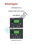
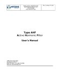
User’s Manual Sinexcel AHF One-Set and Multi-Set System (25~600A) Sinexcel AHF One-Set and Multi-Set System (25~600A) User’s Manual Version: V2.0 Filed date: Aug-21-2012 BOM No.: A81150060 Sinexcel Electric Co., Ltd. provides full technical supports for clients. Users may contact the local agent or customer service center of the company, or the headquarters directly for help. Sinexcel Electric Co., Ltd. All rights reserved, the contents of this manual shall be subject to change without any further notice. Sinexcel Electric Co., Ltd. Address: 6th floor, D1 R&D Building, International E City, 1001# Zhongshan Yuan Road, Nanshan District, Shenzhen Zip Code: 518054 Http://www.sinexcel.com Customer Service Hotline: 86-755-86511588 Fax: 86-755-86513100 E-mail: [email protected] Following components and parts are mentioned in this manual Module Description Sinexcel XXX AHF 4 3L/R L Sinexcel AHF module rating: 25A/35A/50A/60A/75A/100A L:LCD R:Rack mounting H:Wall mounting 3L:3 Phase 3 Line 4L:3 Phase 4 Line For example: Sinexcel XXX AHF 4 3L/R L The rating of Sinexcel AHF is 25A/35A/ 50A/60A/75A/100A, the rated voltage is 400V, the network configuration is 3 phases 4 wires. R means the rack mounting, L means LCD display. Options 4:400V 6:690V AHF:Active Harmonic Filter Rating: 025/035/050/060/075/100 25A/35A/50A/60A/75A/100A Sinexcel:AHF Brand Name Models External CT components Selected by customer CT cable components Decided by using conditions LCD and monitoring components Optional Notes There are several kinds of specifications for LCD models, and the specifications within 150:5-10000:5 are available for LCD models. The quantity of unit is decided by the quantity of seprated machines of the Multi-Set or the installation method, see CT cable components for details. LCD panel is a standard product Notices Please describe the installation method (racking or wall-mounting) when ordering Sinexcel AHF! Safety Precautions This manual describes the installation and operation methods of Sinexcel AHF. Please read the manual carefully before installation. The commissioning and maintenance of Sinexcel AHF shall be conducted by engineer(s) appointed by the manufacturer or the agent, otherwise personal injury and device damages might be caused; the maker shall not be responsible for such kinds of damages. Sinexcel AHF is only for commercial/industrial use, it can’t be used as energy-saving equipment related with any life-support devices. The product is grade A AHF equipment. Wireless disturbance might be caused when it is used as energy-saving equipment, thus additional measures are required in this condition. Normative References This equipment meets CE 73/23 & 93/68 (low voltage safety) , 89/336 (EMC), and the EMC standards (C-Tick) of Austrilia and New Zealand: See Chapter VII Product Specifications for the details. Please install the equipment according to requirements stated above and use the accessaries appointed by the manufacturer. Warning: Heavy Electric Leakage Please connect the ground wire correctly before connecting the equipment to the power supply. The leakage current to ground shall be in the range of 3.5 mA-1,000mA. The steady state and transient state leakage currents produced when starting shall be taken into consideration when you choose instantaneous release RCCB and RCD components. It’s advised to select residual current circuit breakers (RCCBs) that is not sensitive to unidirectional DC pulse (A-grade) and transient current pulse. The leakage current to the ground flows through RCCB or RCD too. The earthing of the equipment must meet local electric regulations. User Serviceable Parts The maintenance of the internal parts of the equipment shall be conducted upon some tools by professional personnel. All compoments and parts that are kept in the protected containers and must be opened by tools, are user nonserviceable. This AHF fully meets the equipment’s safety standards in working zone. There is dangerous voltage with AHF but that only maintenance personnel can access. As the components with dangerous voltage has protective cap which must be opened by tools, thus the possibility of touching dangerous high voltage is very small. There is no any danger when you operate the equipment according to relevant regulations and the procedures specifed in the manual. Dust network maintenance Please according to the site environment choose whether installation anti-dust mesh, dust bigger when must be installed dust network; Such as the installation of dust network, it is required to clean dust and regularly to ensure smooth ventilation, suggest cleaning frequ ency for 1 times/month, the longest cleaning time interval must not exceed 3 months. Contents Chapter I One-Set System Installation .............................................................................................................................................1 1.1 Introduction .................................................................................................................................................................. 1 1.2 Initial Check ................................................................................................................................................................. 1 1.3 Position Selection ......................................................................................................................................................... 1 1.3.1 AHF Installation Position................................................................................................................................... 1 1.3.2 Storage.............................................................................................................................................................. 2 1.4 Positioning.................................................................................................................................................................... 2 1.4.1 Sinexcel AHF .................................................................................................................................................... 2 1.4.2 Cabinet Transport .............................................................................................................................................. 2 1.4.3 Working Space .................................................................................................................................................. 2 1.4.4 Final Positioning ............................................................................................................................................... 2 1.4.5 1.5 Cable-in Method................................................................................................................................................ 3 External Protective Devices........................................................................................................................................... 3 1.6 Power Cable ................................................................................................................................................................. 3 1.7 Monitoring Module ....................................................................................................................................................... 4 Chapter II Multi-Set System Installation..........................................................................................................................................5 2.1 Introduction .................................................................................................................................................................. 5 2.2 AHF One-sets of Multi-Set System................................................................................................................................ 5 2.2.1 Install Multi-Set System .................................................................................................................................... 5 2.2.2 External Protective Devices ............................................................................................................................... 6 2.2.3 Power Cable & Control Cable ............................................................................................................................ 6 2.3 Features of Multi-Set System......................................................................................................................................... 6 2.4 Sinexcel Parallel Connection Requirements ................................................................................................................... 7 Chapter III Installation Diagram .....................................................................................................................................................8 3.1 Introduction .................................................................................................................................................................. 8 3.1.1 Racking module with LCD............................................................................................................................. 8 3.1.2 Wall-mount module with LCD ..................................................................................................................... 11 3.1.1 System terminal........................................................................................................................................... 14 Chapter IV Running and Operating Steps ......................................................................................................................................16 4.1 System Setup and Wiring........................................................................................................................................... 16 4.1.1 System Setup................................................................................................................................................... 16 4.1.2 System Wiring................................................................................................................................................. 16 4.2 Sinexcel AHF Power ON/OFF .................................................................................................................................... 16 4.2.1 Power ON Steps .............................................................................................................................................. 16 4.2.2 Power-OFF Steps ............................................................................................................................................ 17 4.2.3 Automatic startup ............................................................................................................................................ 17 Chapter V Operation and Control Panel ........................................................................................................................................18 5.1 Introduction ................................................................................................................................................................ 18 5.1.1 System Parameters and Waveforms Inquiry...................................................................................................... 18 5.1.2 System Setup................................................................................................................................................... 20 5.1.3 Language Setup ............................................................................................................................................... 20 5.1.4 History Records............................................................................................................................................... 21 5.1.5 Menu Description ............................................................................................................................................ 21 5.1.6 Faults Description........................................................................................................................................ 22 5.2 Power-Saving Mode.................................................................................................................................................... 22 Chapter VI Accessaries.................................................................................................................................................................24 6.1 Current Transformer.................................................................................................................................................... 24 6.2 CT Cable................................................................................................................................................................... 28 6.3 6.4 Connection of Current Transformer............................................................................................................................ 28 6.3.1 CT Installation Direction.............................................................................................................................. 29 6.3.2 CT Terminal Block ...................................................................................................................................... 29 LCD and Monitoring Module..................................................................................................................................... 30 Chapter VII Background monitoring .............................................................................................................................................31 7.1 Introduction ................................................................................................................................................................ 31 7.2 Sinexcel AHF monitoring mode .................................................................................................................................. 31 7.2.1 RS485 interface ............................................................................................................................................... 31 7.2.2 Sinexcel AHF Ethernet monitoring................................................................................................................... 31 7.3 Sinexcel AHF background monitoring software ........................................................................................................... 32 7.4 Sinexcel AHF background monitoring system structure................................................................................................ 33 Chapter VIII Product Specifications ..............................................................................................................................................34 8.1 Standards .................................................................................................................................................................... 34 8.2 Technical Specifications.............................................................................................................................................. 34 Appendix .....................................................................................................................................................................................35 Appendix 1:3P4W network configuration main wiring diagram.......................................................................................... 35 Appendix 2:3P3W network configuration main wiring diagram.......................................................................................... 35 Appendix 3:Selection table................................................................................................................................................ 35 INSTALLATION LOG ................................................................................................................................................................36 Chapter I One-Set System Installation 1 Chapter I One-Set System Installation 1.1 Introduction In this chapter, we shall introduce Sinexcel AHF and the requirements of position selection and wiring of related equipments. As different sites have different conditions, only the general installation procedures and methods shall be introduced for installation personnel. Please install the device according to the actual conditions of the site. Warning: Professional Installation It is not allowed to electrify the AHF unless getting the consent of the engineer after commissioning. AHF shall be installed according to the manual by qualified engineer(s). The specifications and installation instructions of other devices shall be provided when delivery. Note: 3P4W and 3p3w System Power Supply Standard Sinexcel AHF system can be connected with three-phase four-wire (earthing) TN, TT, IT AC distribution system (IEC60364-3) and three-phase four-wire system . For IT AC distribution system, a 4-polar breaker is needed for input, see relevant IT system standards for details. 1.2 Initial Check Before installing AHF, please check the product as follows: 1. Check whether the outside and inside of AHF is damaged in transportation. If there is any damage, please inform the carrier immediately. 2. Check label to confirm the equipment. There is a label affixed on the side of the equipment with AHF model, capacity and other parameters. 1.3 Position Selection 1.3.1 AHF Installation Position Sinexcel AHF is designed to use in the house and should be installed in a clean site with good ventilation to ensure that the environment temperature meets the requirements of the equipment (see table 8-2). Sinexcel AHF is equipped with a built-in fan that provides forced air cooling. The cool air will enter the inside of AHF through the wind grids in front of AHF casing, and the hot air will be discharged through the wind grids at the back of AHF. Do NOT block the vents. Notices If wall-mounting mode is selected, 150mm must be kept at least for air ventilation between the air inlet/outlet and the wall! If standard rack mounting mode is selected, please select the rack that the air can flow through both of the front and back doors. If necessary, the indoor ventilating fan should be installed to avoid room temperature increasing. And air strainer is needed if there is too much dust in the air. Note: Sinexcel AHF can only be installed on the surface of concrete or other nonflammable materials. Three installation methods are available including rack mounting installation, flat mounting installation and wall mounting installation. 2 Chapter I One-Set System Installation 1.3.2 Storage If it is unnecessary to install Sinexcel AHF immediately, it shall be stored in the house and avoid high humidity and high temperature (see table 8-2). 1.4 Positioning Module design is adopted for the case of Sinexcel AHF, which is convenient to the positioning and transport of the equipment. To prolong the service life, the location of Sinexcel AHF shall meet following requirements: Easy to connect wires; Enough operating space; Good ventilation to satisfy the heat emission requirement; No corrosive gas in the air; No devices of producing high humidity and high temperature; Not dusty environment; Satisfy fire control requirement; Working temperature: -5℃—+45℃. Open the upper cover of Sinexcel AHF, you may see power supply terminals and CT input wiring terminals. The control panel in the front of AHF is equipped to display the basic operating states and warning information. For rack mounting installation, the air inlet is in the front and the air outlet is at the back of the equipment; for wall-mounting installation, air inlet is at the lower and the air outlet is at the upper. 1.4.1 Sinexcel AHF As a modular design, in 25 A / 35 A AHF,the height is 200 mm and width is 260 mm. It is very flexible to install with the small dimensions and light weight. In 50 A / 60 A AHF, the height is 200 mm, and in 75 A / 100 A AHF, the height is 232 mm. In both of them, the width are standard 19 inches cabinet size, so the AHF can be chose to install in the 19 inches cabinet shared with the other equipment. It can also be placed in other cooling cabinet equipment above, in order to save a space, recommend direct articulated near the wall of the load. 1.4.2 Cabinet Transport Warning As each Sinexcel AHF module is about 16kg~40kg, two persons are enough for short-distance transport; but for long-distance transport, the transport equipments shall be needed. Make sure that the weight of Sinexcel AHF is within the loading capacity of small transport equipment, see table 8-5 Small trailer or other similar transport equipment can be used to transport Sinexcel AHF. 1.4.3 Working Space There are grids on both sides of Sinexcel AHF, proper space is needed to be left. If it will be installed in the standard 19-inch cabinet, the space stated above is unnecessary. To fix the power supply terminals inside the AHF during normal operation, the installation must meet the local regulations, and there should be enough space at the back of AHF for the work of maintenance personnel. After all wires are connected, there must be enough space (150mm at least) to keep good ventilation. 1.4.4 Final Positioning In the front of Sinexcel AHF case, there are some joints to connect the case and the cabinet. On the side of the case, there are structures used to fix the case on the wall. Before the final position, please select the proper installation position and method in advance. Chapter I One-Set System Installation 3 1.4.5 Cable-in Method Back Cable-in method and upper Cable-in method are provided, the selection of Cable-in method is decided by the installation method of AHF. During wiring, remove the upper cover to access to the Cable-in hole and connection terminals. 1.5 External Protective Devices A breaker or other protectors shall be installed at the place of external AC power supply input of Sinexcel AHF system. This chapter provides general instructions for qualified installation engineer, who shall learn about the local installation regulations of equipments to be installed. Overcurrent A proper overcurrent protector shall be installed for the electric supply input distribution, and the current capacity and overload capacity of power cable shall be taken into consideration. When the current is 125% of that stated in Figure 1-1, thermomagnetic breaker of IEC 60947-2 tripping curve C (normal) is advised. Notice For IT electric-net system, four-polar protector is needed to be installed for external input distribution and external output distribution of Sinexcel AHF. Earth leakage current (RCD) Residual current device (RCD) for previous input distribution of Sinexcel AHF must meet following requirements: Being sensitive to the unidirectional DC pulse (A-grade) of distribution network Being insensitive to transient current Having common sensitivity and the value can be adjusted within range of 0.3-1A Figure 1-1 Signs of Leakage Current Breaker (RCCB) To avoid wrong warning when the earth leakage current tester is used in the Multi-Set system, the earth leakage current tester shall be installed on the previous input distribution terminal. The filter RFI inside AHF shall have an earth leakage current within the value range from 3.5mA to 300mA. Please confirm the sensitivity of each differential of previous input distribution and next distribution (to load). 1.6 Power Cable Designing the cable according to instructions stated in this chapter and the local wiring regulations, and taking the environment conditions into consideration. Warning Before the wiring of Sinexcel AHF, please make sure you clearly know the position and state of the switches connecting AHF’s input power and electric supply distribution. Make sure these switches are in off state, and affix warning labels to avoid other people’s operations to these swithes. Table 1-1 Power cable connection fixed bolt and moment model Voltage class/terminal Sinexcel 025/035 AHF Sinexcel 050/060/075/100 AHF Bolt specifications Bolt specifications Input cable Torque Input cable Torque 4 Chapter I One-Set System Installation 380V/400V bolt aperture(mm) (Nm) bolt aperture(mm) (Nm) A/B/C/PE M6 6 4 M8 8 6 N M6 6 4 M8 8 6 Note: 1. The current of neutral cable may exceed rated current, generally it’s 1.732 times of the rated current, and the system shall be designed by 3 times of the rated current. 2. Protective earth wire: When connecting the cabinet and the main earth system, the shortest length wiring method should be adopted. Earth wire should be selected with available cross sectional area according to power failure class, cable length and protective type. According to AS / IEC 60950-1, 16mm2 is advised. 3. See Chapter III Installation Diagram for positions of connection terminals. Warning Violation of earth requirements might cause electromagnetic interference, electric shock and fire. Table 1-2 Distance between Joint Point of Equipement and the Floor AHF Sinexcel AHF Minimum Distance (mm) Input Terminal 284 Important The operations stated in this section must be conducted by authorized persons. Please contact the customer service department of our company if there is any problem. After final positioning of the equipment, please refer to the wiring diagram in Chapter III to connect the power cables as per the following steps: 1. Confirm that all the distribution switches of Sinexcel AHF are turned off, and affix warning labels beside these switches to avoid other people’s operations. 2. Open the upper cover of Sinexcel AHF to access to the terminal base connecting power cable. 3. Connect the protective earth and other earth cables to the earth connection point PE of Sinexcel AHF (PE is on the same PCBA with connection base of input cable). All the AHF cabinets shall be earthed). Note: the wiring of earth wire and central wire must meet related local and national regulations. 4. Mark and connect the input cables according to installation type. Warning If the AHF hasn’t been installed when the debugging engineer arrives, please make safe insulation to the power cables that are used t connect to the AHF. 5. Re-fit all protective covers. 1.7 Monitoring Module According to the detailed requirements of site, auxiliary connections may be needed to realize functions of man-machine communication, warning signal provided to external equipments, and remote emergent stop, etc. These functions can be realized through monitoring panel on the side of the front panel of AHF. There are following ports and interfaces on the monitoring panel: User communication port (used to set up parameters and realize background monitoring function); Internet port. Note: these function shall be valid only after setting through software, password is needed to complete relevant settings. Chapter II Multi-Set System Installation 5 Chapter II Multi-Set System Installation 2.1 Introduction Please install Multi-Set system according to the installation steps of one-set system and the requirements hereunder. 2.2 AHF One-sets of Multi-Set System The basic installation steps of Multi-Set system are as same as one-set system. The different installation steps between multi-Set system and one-set system shall be described in following sections. 2.2.1 Install Multi-Set System Place all one-sets in a row and connect them according to Figure 2-1. For the convenience of maintenance and system testing, electric power distribution cabinet is advised. Theoretically speaking, the quantity of Sinexcel AHF in Multi-Set system isn’t been limited. However, in consideration of the circuit testing precision, six units are advised at most, and thus a better equal current of each AHF in the Multi-Set system can be realized. Figure 2-1 Installation Diagram of N units of AHF in Multi-Set System Figure 2-2 and 2-3 describe the installation diagram of rack mounting AHF parallel connection in cabinets, including 6 units of Sinexcel 050 AHF (total capacity of 300A) or 6 units of Sinexcel 100 AHF (total capacity of 600A). Figure 2-4 describes the installation diagram of units of wall mounting AHF parallel connection. 6 Chapter II Multi-Set System Installation Figure 2-2 Installation Diagram of rack mounting AHF parallel connection ( 6 units of 50A) Figure 2-3 Installation Diagram of rack mounting AHF parallel connection ( 6 units of 100A) Figure 2-4 Wall-mounting Parallel Connection Diagram (N units) 2.2.2 External Protective Devices See Chapter I One-set System Installation 2.2.3 Power Cable & Control Cable The power cable layout is as same as that of one-set system. Note: the power cables’ length and specifications of each one-set should be same; especially, the length of the control cables’ from the external CT to each one-set must be same to realize equal current flow. The length in 5m, 10m and 15m of cabels are provided for selection. If you need cable longer than 15m, the cable needs some special treatment (such as sstrengthen the shield or use smaller resistivity cable). If you need cable longer than 30m, please contact Sinexcel Electric in advance. 2.3 Features of Multi-Set System 1. For Multi-Set system, the hardware and software of Sinexcel AHF are as same as that of one-set system and the configuration of Multi-Set system can be made by parameters setup software. Chapter II Multi-Set System Installation 7 2. It’s easy to control the wire connection, which contributes to the reliability improvement of the system and convenience for maintenance on site. 3. The user can read the total loads of the Multi-Set system through the LCD of each one-set. 2.4 Sinexcel Parallel Connection Requirements An AHF system comprising multiple one-sets functions as a large AHF system, however, the Multi-Set system has higher system reliability. To ensure that all one-sets are to be used equally under related wiring regulations, following requirements should be met: 1. All the one-sets must be the same model made by the same manufacturer. 2. If the residual current device (RCD) is needed, after correct setup, it must be installed before the same central cable input terminal. Or the device must monitor the leakage current of the protected ground of the Multi-Set system. See “Warning: Heavy Electric Leakage”. 3. The output of all the Sinexcel one-sets shall be connected to the common output terminal. 8 Chapter III Installation Diagram Chapter III Installation Diagram 3.1 Introduction In this chapter we shall mainly introduce the installation size of Sinexcel AHF series so as to provide convenience for the user to fix and install. To satisfy the requirements of different users, two kinds of different appearance designs are provided, including Racking module with LCD and wall-mount module with LCD. 3.1.1 Racking module with LCD In Figure 3-1, Racking with LCD of Sinexcel 025/035 AHF’s size and installation position are described; the user may design fixing holes and install the equipment according to the sizes in the Figure. The 3D view is shown in Figure 3-5. 260 89 200 40 455 486 Figure 3-1 Racking with LCD of Sinexcel 025/035 AHF’s Size and Installation Diagram In Figure 3-2, Racking module with LCD of Sinexcel 050/060 AHF’s size and installation position are described; the user may design fixing holes and install the equipment according to the sizes in the Figure. The 3D view is shown in Figure 3-6. Chapter III Installation Diagram Figure 3-2 Racking with LCD of Sinexcel 050/060 AHF’s Size and Installation Diagram In Figure 3-3, Racking module with LCD of Sinexcel 075 AHF’s size and installation position are described; the user may design fixing holes and install the equipment according to the sizes in the Figure. The 3D view is shown in Figure 3-7. 484 466 440 R3,5 232 89 71,5 575 606 Figure 3-3 Racking with LCD of Sinexcel 075 AHF’s Size and Installation Diagram In Figure 3-4, Racking module with LCD of Sinexcel 100 AHF’s size and installation position are described; the user may design fixing holes and install the equipment according to the sizes in the Figure. The 3D view is shown in Figure 3-8. 9 10 Chapter III Installation Diagram 484 466 R3,5 440 89 232 71,5 575 606 Figure 3-4 Racking with LCD of Sinexcel 100 AHF’s Size and Installation Diagram Figure 3-5 Racking with LCD of Sinexcel 025/035 AHF’s 3D view Figure 3-6 Racking with LCD of Sinexcel 050/060 AHF’s 3D view Chapter III Installation Diagram Figure 3-7 Racking with LCD of Sinexcel 075 AHF’s 3D view 3.1.2 11 Figure 3-8 Racking with LCD of Sinexcel 100 AHF’s 3D view Wall-mount module with LCD In Figure 3-9, Wall-mount module with LCD of Sinexcel 025/035 AHF’s size and installation position are described; the user may design fixing holes and install the equipment according to the sizes in the Figure. The 3D view is shown in Figure 3-13. 260 200 436 460 180 Figure 3-9 Wall-mount with LCD of Sinexcel 025/035 AHF’s Size and Installation Diagram In Figure 3-10, Wall-mount module with LCD of Sinexcel 050/060 AHF’s size and installation position are described; the user may design fixing holes and install the equipment according to the sizes in the Figure. The 3D view is shown in Figure 3-14. 12 Chapter III Installation Diagram Figure 3-10 Wall-mount with LCD of Sinexcel 050/060 AHF’s Size and Installation Diagram In Figure 3-11, Wall-mount module with LCD of Sinexcel 075 AHF’s size and installation position are described; the user may design fixing holes and install the equipment according to the sizes in the Figure. The 3D view is shown in Figure 3-15. 440 232 235 601 625 360 Figure 3-11 Wall-mount with LCD of Sinexcel 075 AHF’s Size and Installation Diagram Chapter III Installation Diagram In Figure 3-12, Wall-mount module with LCD of Sinexcel 100 AHF’s size and installation position are described; the user may design fixing holes and install the equipment according to the sizes in the Figure. The 3D view is shown in Figure 3-16. 440 232 601 235 625 360 Figure 3-12 Wall-mount with LCD of Sinexcel 100 AHF’s Size and Installation Diagram Figure 3-13 Wall-mount Sinexcel 025/035 AHF’s 3D view Figure 3-14 Wall-mount Sinexcel 050/060 AHF’s 3D view 13 14 Chapter III Installation Diagram Figure 3-15 Wall-mount Sinexcel 075 AHF’s 3D view 3.1.1 Figure 3-16 Wall-mount Sinexcel 100 AHF’s 3D view System terminal Figure 3-17 and 3-18 are Sinexcel 025/035 AHF’s wiring diagrams, from which we can see the positions of terminals of power cable and CT cable. CT_C CT_B CT_A CT_C CT_B CT_A CT_C_GND CT_B_GND CT_C_GND CT_B_GND CT_A_GND CT_A_GND PE PE NN CB NN A Figure 3-17 Racking Sinexcel 025/035 AHF’s wiring diagram CB A Figure 3-18 Wall-mount Sinexcel 025/035 AHF’s wiring diagram Figure 3-19 and 3-20 are Sinexcel 025/035 AHF’s wiring diagrams, from which we can see the positions of terminals of power cable and CT cable. CT_C CT_B CT_A CT_C CT_B CT_A CT_A_GND CT_C_GND CT_B_GND CT_A_GND PE CT_A_GND CT_A_GND PE N C B A Figure 3-19 Racking Sinexcel 050/060 AHF’s wiring diagram N C B A Figure 3-20 Wall-mount Sinexcel 050/060 AHF’s wiring diagram Figure 3-21 and 3-22 are Sinexcel 075 AHF’s wiring diagrams, from which we can see the positions of terminals of power cable and CT Chapter III Installation Diagram 15 cable. CT_C CT_C CT_B CT_A CT_B CT_A CT_C_GND CT_B_GND CT_A_GND PE CT_C_GND CT_B_GND CT_A_GND PE N C B N C B A Figure 3-21 Racking Sinexcel 075 AHF’s wiring diagram A Figure 3-22 Wall-mount Sinexcel 075 AHF’s wiring diagram Figure 3-23 and 3-24 are Sinexcel 100 AHF’s wiring diagrams, from which we can see the positions of terminals of power cable and CT cable. CT_C CT_C CT_B CT_A CT_B CT_A CT_C_GND CT_B_GND CT_A_GND PE CT_C_GND CT_B_GND CT_A_GND PE N C B N C B A Figure 3-23 Racking Sinexcel 100 AHF’s wiring diagram A Figure 3-24 Wall-mount Sinexcel 100 AHF’s wiring diagram Chapter IV Running and Operating Steps 16 Chapter IV Running and Operating Steps Warning: Electric shock danger behind the protective cover. No user serviceable parts inside the protective cover. Only the qualified personnel are allowed to open the cover. Suggestion: it’s advised to use a breaker between AHF and power supply! 4.1 System Setup and Wiring 4.1.1 System Setup The external CT transformation ratio and the operation mode of Sinexcel AHF should be set through the LCD screen in the front of AHF case. The detail is show in chapter V The Operation and Control Panel. 4.1.2 System Wiring Sinexcel AHF has six main wiring terminals with outside; refer to 3.1.3 System Wiring Terminal for details. Input A—A phase input terminal Input B—B phase input terminal Input C—C phase input terminal N—Neutral input terminal PE—system earth terminal, as the housing of the system is metallic, in order to avoid personal accident, please connect the earth via this terminal before powering on the system. J14, J15 or J36 or J67, J68 - external CT vice edge terminals, J14, J15 (50A / 60A) or J36 (25A/ 35A) or J67, J68 (75A/ 100A) terminal from the outside joint in maximum allowable current for 5A J14, J15 or J36 or J67, J68 has six wiring positions in total and refer to table 4-1 for details: Table 4-1 External CT terminal corresponding table J14、J15 terminal J36 terminal J67、J68 terminal Label Description J14-3 J36-1 J67-3 CT_A S1 terminal connecting to A phase CT J14-2 J36-2 J67-2 CT_A_GND S2 terminal connecting to A phase CT J14-1 J36-3 J67-1 CT_B S1 terminal connecting to B phase CT J15-3 J36-4 J68-3 CT_B_GND S2 terminal connecting to B phase CT J15-2 J36-5 J68-2 CT_C S1 terminal connecting to C phase CT J15-1 J36-6 J68-1 CT_C_GND S2 terminal connecting to C phase CT Refer to chapter VI for the installation of CT. 4.2 Sinexcel AHF Power ON/OFF After installation and commissioning by the engineer, the user may power on Sinexcel AHF. 4.2.1 Power ON Steps It’s applicable to the power-on operation when AHF is in power-off state. The operating steps are described as follows: 1. Fix the upper cover of Sinexcel AHF. Chapter IV Running and Operating Steps 17 Warning AHF output terminal shall be electrified when powering on AHF. If the load is connected to AHF output terminal, please confirm whether it’s safe to electrify the load. If the load is not ready to be electrified, DO keep the load away from AHF output terminal. 2. Close the disconnecting switch which disconnecting the power supply and AHF The LCD screen will be light and the LED indicator light flickers in green color by doing so. And about 20 seconds later, the indicator light will be green in steady. If there are faults in equipment, the LED indicator will be red, and the AHF cannot be power on. 4.2.2 Power-OFF Steps There are two kinds of power-off modes, one is to disconnect the switch of AHF and power supply, in this mode, the system shall be thoroughly powered off and it may conduct maintenance and setup work, the other one is to press the switch button on LED panel, in this mode, it shall close the power parts of the system only and the bus bar and auxiliary power still exist, the control system is in standby status, further press the switch button to start AHF directly. In this mode, it’s not allowed to conduct maintenance and setup work. Warning In order to avoid personal hurt, if you want to repair or dismantle the housing after powering off, please test the input terminal by the multimeter to ensure no power inside! It’s advised to open the cover five minutes later after powering off. 4.2.3 Automatic startup If the occurrence of power cut or abnormal voltage or frequency, Sinexcel AHF shall be automatically powered off and stop outputting the compensation current. If the following requirements are met, Sinexcel AHF shall be automatically restarted: Power supply is normal Sinexcel has set in the auto start function After prolonging via auto start (default 10 seconds) If Sinexcel AHF has not set up the auto start function, the user may start AHF by pressing ON/OFF key. 18 Chapter V Operation and Control Panel Chapter V Operation and Control Panel 5.1 Introduction This chapter mainly introduces the LCD display and setup parameters, the user may operate and control the device through LCD. LCD user-friendly interface has 320*240 dot matrix display, LCD may give real-time alarm message and provide 500 alarm records for inquiry that are reliable basis for fault diagnosis. The user may make operations through LCD panel, view the input/output/load parameters and waves, and get the current working status and alarm message of Sinexcel AHF. The LCD can also display the version information of system software and monitoring software. The panel has two functional parts: LCD display and menu/operation keys. Sinexcel AHF-50-400-4L 2010-12-01 M130D180 09:00:00 Normal Voltage Current Harmonics Analysls Temperature Settings Alarm Events Power ON/OFF Sinexcel Electric Co., Ltd. Up Down Enter Esc Normal Alarm Figure 5-1 Sinexcel AHF operation and control panel Table 5-1 Sinexcel AHF operation and control panel parts description Buttons/Indicators Up Down Enter Esc Normal Alarm Functions Move upwards Move downwards Confirm key Cancel key System is normal System fault Additional instructions of the buttons: Press the Up and Down simultaneously, turn into the Power OFF menu; Press the Up and Enter simultaneously, the LCD screen will be lighter; Press the Down and Enter simultaneously, the LCD screen will be darker; Press the Esc and Enter simultaneously for 10 seconds, turn into the senior parameter settings menu (the function only for special personnel). 5.1.1 System Parameters and Waveforms Inquiry We can inquiry following system parameters by the LCD screen: grid voltage, frequency, load current, compensated current and THDI, load harmonic current and the spectrum. Figure 5-2 is the menu of voltage. Chapter V Operation and Control Panel Sinexcel 2010-12-01 09:00:00 AHF-50-400-4L M130D180 Normal Phase A Voltage 224.78V 19 Frequency THDU 49.95Hz 2.3% RMS Voltage L1-Voltage Waveform L2-Voltage Waveform L3-Voltage Waveform Sinexcel Electric Co., Ltd. Figure 5-2 voltage Figure 5-3 voltage waveform We can see the 3-phase grid voltage, frequency as well as the THDU of from the interface as figure 5-2 shown. We can see the phase voltage information from the menu in figure 5-3 by pressing the Enter button. Sinexcel 2010-12-01 09:00:00 AHF-50-400-4L M130D180 Normal Sinexcel 2010-12-01 09:00:00 AHF-50-400-4L M130D180 Normal Load Current RMS Load Current Comp.Current L1-Current Waveform L2-Current Waveform Grid Current Sinexcel Electric Co., Ltd. Figure 5-4 current L3-Current Waveform Sinexcel Electric Co., Ltd. Figure 5-5 RMS load current Select Current in the main interface to enter the current selection interface as figure 5-4 shown to view the parameters and waveforms, select Load Current option to enter the corresponding interface as figure 5-5 shown to view the 3-phase current and THDI, if you want to view the waveforms, select the corresponding phase and then press Enter to view. In the same way, If we want to view harmonic analysis, please press the Enter button to enter the interface as figure 5-6 shown. Sinexcel 2010-12-01 09:00:00 AHF-50-400-4L M130D180 Normal L1 load THDI 65.6% Grid THDI 1.9% THD Voltage&Current L1-Harmonic Spectrum L2-Harmonic Spectrum 1 5 10 15 20 25 30 35 40 45 50 L3-Harmonic Spectrum Sinexcel Electric Co., Ltd. Figure 5-6 harmonic analysis 1 5 10 15 20 25 30 35 40 45 50 Figure 5-7 harmonic spectrums From figure5-6, we can view the information about grid voltage THDU, load current THDI and grid current THDI by selecting the THDI voltage & current. Also we can view the relevant harmonic spectrums by press the Enter button if we want to know the spectrums. For example, if we want to view the THDI of L1, please select L1 – harmonic spectrum and press the Enter button to enter the interface 20 Chapter V Operation and Control Panel as 5-7 shown. We can clear know that the comparison of L1 load current THDI of before compensation and after compensation. We can know the difference between before compensation and after compensation. Select the temperature and press the Enter button to enter the interface as figure 5-8 shown. Sinexcel AHF-50-400-4L Internal Internal Internal Internal Internal Internal 2010-12-01 M130D180 09:00:00 Normal Temp.[1]:65℃ Temp.[2]:65℃ Temp.[3]:65℃ Temp.[4]:65℃ Temp.[5]:65℃ Temp.[6]:65℃ Sinexcel Electric Co., Ltd. Figure 5-8 temperature From figure 5-8, we can know that there 6 temperature in all. The internal temp.1 to 3 show the temperature of inverters in L1 to L3. The temperature 4 to 6 show the partial temperature in the AHF. We can clear know the status of temperature in the internal AHF. 5.1.2 System Setup There are 3 kinds of settings in the system settings as shown in figure 5-9. The user may enter the interface by entering the password, the people who haven’t password shall not be allowed to enter, only the personnel who are trained by Sinexcel can operate! In this interface, there are many settings options including system parameters, system display, and system communication. We can enter each menu by selecting the submenu and pressing the Enter button. Entering the system display settings interface as the figure 5-10 shown, we can move the cursor by pressing the Up/Down button, then the cursor is blinking, so the settings will be changed by pressing the Up/Down button, and the press the Enter to finish the settings. Other settings is no longer to introduce in the section, all the settings shall be saved in the system. Sinexcel 2010-12-01 09:00:00 AHF-50-400-4L M130D180 Normal System Display Setting LCD Brightness:23 System Parameter Setting Time:09:00:00 System Display Setting System Communication Setting Date:2010-12-01 Language:English Sinexcel Electric Co., Ltd. Figure 5-9 system settings 5.1.3 Figure 5-10 system display settings Language Setup Sinexcel AHF there are two national languages are available, before they leave the factory default Settings for Chinese, users can on the spot according to the need for the corresponding Settings, two languages respectively is: Chinese and English. Chapter V Operation and Control Panel 5.1.4 21 History Records The history records shall record all faults in running including the fault types, starting time and ending time, to facilitate the maintenance personnel to find the fault and make proper maintenance. General the history records are not allowed to be cleared. 5.1.5 Menu Description Detailed description of the LCD display window as shown in figure 5-1. Sinexcel AHF system information window: to display the basic information of AHF including time, date, AHF name and the configuration and status. It’s unnecessary for the user to operate. The details are described as follows: Table 5-2 AHF system information window items description Display Description AHF name Date (format: Y-M-D) Time (format: 24H, H:M:S) 25/35/50/60/75/100: means ther rated output current is 25/35/50/60/75/100A; 400: means the rated voltage is 400V; 4L: means the network configuration is 3P4W, 3L means the 3P3L. M: monitoring version; D: control software version Normal: AHF is normally working Stop: AHF is in standby mode Fault: AHF fuse or hardware has fault Sinexcel 2012-05-29 15: 02:30 AHF-25/35/50/60/75/100-400-4L M130D180 (Status) Normal,Stop, Fault AHF menu window and data window Use UP/DOWN/ENTER/ESC key to select. Table 5-3 AHF menu window and data window items description Menu Name Voltage Items Voltage (V) RMS Voltage Frequency (Hz) THDU (%) Phase voltage Frequency Total harmonic distortion of Voltage L1/L2/L3 - Waveform Phase voltage waveform Load Current (A) RMS Load Current Load I Load PF Load phase current Power factor of load phase THDI Load phase current THDi Waveform Current Compens ated Current (A) Grid Current (A) Harmonic Analysis Temperature RMS Comp. Current current waveform of L1/L2/L3 Comp. I System compensated current of L1/L2/L3 Load Rate Proportion of the compensation current in the rated output current Grid I Grid PF THDI Current waveform of L1/L2/L3 Grid phase current Power factor of grid phase Grid phase current THDi Current waveform of L1/L2/L3 Waveform RMS Grid Current Waveform THD Voltage & Current Grid THDI Grid phase current THDi Load THDI THDU Load phase current THDi Load THDi and column diagram Harmonic Spectrum Harmonic spectrum before and after compensation Internal Temp. [1] to [3] The inverters temp. of L1/L2/L3 Internal Temp. [4] to [6] The partial temperature of inductance board Op. Mode Settings Description System Parameter Settings CT Ratio CT Location PT Ration Harmonic comp. setting Setup the operation mode of AHF, harmonic compesation, harmonic and reactive power compersation, load balancing and auto-aging (this mode CANNOT be selected by costomers). External CT ration , such as 300:5 or 600: 5... Should be selected in the load side or supply side The ration of the transformer Should be selected in sequential, intelligent or all. 22 Chapter V Operation and Control Panel Menu Name Alarm Events Power ON/OFF 5.1.6 Items Individual Slave Module Quantity Total Capacity Setting Power ON Mode Setting LCD Brightness Setting System Display Time Settings Date language RS485 Adress RS485 Band Rate System RS485 Protocol Communication Settings IP Address Gateway IP Subnetmask IP Active Alarm Events History Alarm Events Description Selecte the 2nd to 50th order harmonic Power ON Confirm power ON Power OFF Confirm power OFF Clear Fault Clear the fault in order to restar the AHF Setup the quantity of slave module The total capacity of milt-set system Should be selected in auto or manual Adjust the LCD screen brightness Setup the time Setup the date Chinese or English are available Monitoring address The transformation times of carrier wave in unit time China TelCom or Modbus are available Matches to the setting in computer Matches to the setting in computer Matches to the setting in computer The active alarm events No., name and occurrence time The history alarm events No., name, occurrence time and end time Faults Description Table 5-4 is the faults of Sinexcel 050 AHF with LCD, it shall help the user easily find the fault and solve. Table 5-4 AHF Faults Description Voltage Abnormal Frequency Abnormal Output Overload Inverter Fault Inverter Over-temperature Fan Fault Power Fault Fuse Fault Inverter Over-current CT Fault Busbar Over-voltage The input voltage is not within the range of 132V-264V The AV input frequency is not within the range of 40-70Hz The load end adds overload or overload short circuit Busbar voltage is too low or too high The temperature of the radiator of inverter is too high and the inverter stops working. The alarm is given by the temperature monitoring signal at the outlet of radiator of inverter. After the temperature is lowered down in 5 minutes, AHF shall be automatically run. If the temperature is too high, please check: 1. Whether the environmental temperature is too high; 2. Whether the outlet is blocked; 3. Whether the fan has fault. There is at least one fan having fault Auxiliary power board has fault There is at least one fuse breaking, the system is powered off. The pulse width module of the inverter is over-current The setup of CT transformation ratio is not correct DC busbar voltage is too high and the system is powered off, after the fault is solved, the inverter shall be started again. 5.2 Power-Saving Mode If no any operation is made within two minutes, the system shall enter power-saving mode and the backlight shall be turned off. Press any one key to activate the screen display. Chapter V Operation and Control Panel Figure 5-11 Power-saving mode 23 24 Chapter VI Accessaries Chapter VI Accessaries 6.1 Current Transformer As an external part of Sinexcel AHF, the current transformer plays a key role in the running of AHF, it’s very important for AHF to select a proper current transformer. In Sinexcel AHF series, the minimum CT transformation ratio is 150: 5 and the maximum is 10000:5. For the AHF series with LCD and monitoring modules, the transformation ratio of CT may be set up from 150:5 to 10000:5. Notices When buying CT, DO check the transformation ratio of CT is allowed by Sinexcel, and check whether the external CT ratio is consistent to the actual CT ratio, if it’s not, it might cause abnormity or bad effect. The precision of external current transformer is required higher than 0.2, if lower one is selected, the compensation precision of Sinexcel might be affected. Notices When selecting CT transformation ratio, it’s advised to select according to the load current, as it may make better harmonic compensation to produce better effect. It is recommended that the input current of CT is 2~4 times to the load current. For example, if the maximum load current is 1000A, 2000:5~4000:5 is the better selection. External CT is required to select three in 3-phase 4-wire to respectively install on L1, L2 and L3, required to select two in 3-phase 3-wire to respectively install on L1 and L3. As an optional part, the user may select split or fix type current transformer, and the split CT is easy to be installed, while fix CT must be installed in case of power disconnection of customer terminal. Note: external CT of Sinexcel AHF is advised to be installed at the load side, namely CT is installed between Sinexcel AHF and the load, in this way, only three CTs can meet the demand, as shown in figure 6-1: refer to table 4-2 for the detailed wiring numbers. CT S1 SOURCE LOAD S2 Sinexcel AHF Figure 6-1 CT installation diagram (load side) There are three ways to choose if the CTs are installed at the load side with the capacitance in the input side of load, as shown in figure 6-2. Chapter VI Accessaries 25 CT S1 SOURCE LOAD S2 CT S1 S2 C Sinexcel AHF Figure 6-2(1) CT installation diagram (load side) CT S1 SOURCE LOAD S2 C Sinexcel AHF Figure 6-2(2) CT installation diagram (load side) CT S1 SOURCE LOAD S2 C Sinexcel AHF Figure 6-2(3) CT installation diagram (load side) It is suggested that the CTs can be installed at the supply side if the load side is not suitable for the CT installation. Three CTs are installed on phase A, B and C, as shown in figure 6-3. The arrows direction is the positive direction which should keep the same with the one in the shell of CT. 26 Chapter VI Accessaries CT S1 LOAD SOURCE S2 Sinexcel AHF Figure 6-3 CT installation diagram (supply side) There are two ways to choose if the CTs are installed at the supply side with the capacitance in the input side of load, as shown in figure 6-4. CT S1 LOAD SOURCE S2 C Sinexcel AHF Figure 6-4(1) CT installation diagram (supply side) CT S1 SOURCE LOAD S2 1 S1 S2 CT C Sinexcel AHF Figure 6-4(2) CT installation diagram (supply side) The way to install CTs with the capacitance in the input side of load is shown in figure 6-5. Chapter VI Accessaries 27 CT S11 LOAD SOURCE S22 CT S1 S2 C Sinexcel AHF Figure 6-5 CT installation diagram (supply side) The parallel connection of two CTs’ output side is shown in figure 6-6: S2 S1 Sinexcel AHF S1 S2 Figure 6-6 CT output side connections diagram (load side) CT S1 LOAD SOURCE S2 A S1 S2 CT Sinexcel AHF B 1# Sinexcel AHF C N# Figure 6-7 CT output side connections diagram (load side) In the parallel connection system, if the current transformer can be installed between Sinexcel and load, it’s allowed to install two current transformers that have consistent transformation ratio, one is installed at the power side and the other one is installed at the output 28 Chapter VI Accessaries terminal of the system. And then connect the two CT output terminals in parallel and install on J14/J15/J36/J67/J78 terminal of Sinexcel, the installation mode of two CTs is described as figure 6-7 shown, the arrowhead’s direction must be consistent to the arrowhead’s direction on the housing of CT. and the length of signal cable AB must be equal to AC. Remark: Load side and supply side are both suitable for single AHF. But in parallel configuration system, only the load side is suggested. 6.2 CT Cable In Sinexcel AHF products, CT cable is also an optional part. All of the cables are twisted line, each group comprises six cables: yellow + black, green + black and red + black. Notices Six cables have same length in each group for accurate work of the system. Each phase of cable is required to use twisted-pair, the shield twisted-pair is better, to avoid the interruption of other signals! For parallel connection of CT output side: Please note that when multiple sets are connected, the selection of CT cables is very important, as multiple Sinexcel AHFs use one external CT, consequently the CT cables connecting to each Sinexcel AHF should have same length, if one set uses 10 meters long cable, and then other five sets must also use 10 meters long cables, which shall ensure consistent communication and realize the optimal effect. Meanwhile when multiple sets are connected, it requires the CT cable of each set should be connected to the CT wiring terminal from external CT terminal, as shown in figure 6-8. L1 and L2 have same length. For series connection of CT output side: It’s allowed to directly connect one to another, as shown in figure 6-9. Sinexcel AHF S1 L1 S1 S2 Sinexcel AHF S1 S2 L2 S2 Figure 6-8 parallel connection of CT output side Sinexcel AHF S1 S1 S2 S1 Sinexcel AHF S2 S2 Figure 6-9 series connection of CT output side The CT cable specification depends on the length. The STP cable RVVSP 2×2.5 should be suggested for Sinexcel AHF while the length is less than 15m, the RVVSP 2×4 should be suggested for Sinexcel AHF while the length is more than 15m and less than 30m, and please contact Sinexcel Electric while the length is more than 30m. 6.3 Connection of Current Transformer When connecting and installing external CT, it’s specified to connect yellow line to L1, green line to L2 and red line to L3. Take yellow line as example, connect the yellow line to S1 terminal of CT1 and black to S2 terminal of CT1, as the same, connect green line to S1 Chapter VI Accessaries 29 terminal of CT2, black to S2 terminal of CT2, red line to S1 terminal of CT3, and black to S2 terminal of CT3. The connection of yellow/green/red twisted line and Sinexcel AHF is referred to table 4-2. 6.3.1 CT Installation Direction We have marked the CT installation direction in the figures of 6.1, and here we shall further detail the cable-in direction as figure 6-10 shown. PE P2 P1 L1 P2 L2 P2 L3 P1 P1 Neutral Figure 6-10 CT cable-in direction diagram 6.3.2 CT Terminal Block When external CT is connected to the system, the terminal of CT auxiliary cable must be shortly connected as figure 6-11 shown, it can’t be disconnected until the CT auxiliary cables is connected to the corresponding terminal of Sinexcel AHF. The short circuit device is not provided and the user should buy additionally when connecting CT. For safety, please assure that the output side of CT in short circuit status and connect to the PE line. L1 L2 L3 Shortcircuit Sinexcel AHF Figure 6-10 CT cable connection diagram 30 6.4 Chapter VI Accessaries LCD and Monitoring Module The standard Sinexcel AHF products are equipped with LCD and it’s unnecessary for the user to buy additionally. Refer to chapter V for the operation and functions of LCD. Chapter VII Background monitoring 31 Chapter VII Background monitoring 7.1 Introduction As is known to all, DSP technology is wide use with its high ability in digital processing. Sinexcel AHF background monitoring system based on the DSP, which can complete the high rate data processing and meet the system real time requirement. 7.2 Sinexcel AHF monitoring mode China TelCom and Modbus protocols are available in AHF communication using RS 485 communication interface and the Et hernet communication interface as figure 7-1 shown Figure 7-1 Sinexcel 050/060 AHF Communication interface diagram Note:Only one used for serial communication, the other two used for centralized monitoring. 7.2.1 RS485 interface RS485 interface: the optimal serial interface due to the advantage in excellent resistance to noise interference, long transmission distance and multistation ability RS485 communication interface was shown in figure 7-2. Figure 7-2 RS 485 communication interface diagram Note:PIN3 to RS 485+,Pin 4 to RS 485-,Pin 5 to GND,the AHF is fixed the male head. Sinexcel 025/035 AHF has a serial port of standard RS485 interface. Sinexcel 050/060 AHF has three serial ports of standard RS485 interface. 7.2.2 Sinexcel AHF Ethernet monitoring Sinexcel AHF monitoring system can realizing data acquisition, real time control and network communication base on TI Company’s 32-bit TMS470 chip, embedded UC/OS - Ⅱ operating system, with all kinds of control program. Monitoring board is similar to a PC machine by integrating Ethernet interface, supporting the TCP/IP protocol, having its own IP 32 Chapter VII Background monitoring address. We can monitor and control the status of AHF by input the IP Address through IE browser, because of there is an embedded Webserver in the AHF. Ethernet (LAN): Ethernet connection needs switch, setting up the fixed IP address and using connecting cable named twisted pair (namely network cable). The expansion board is integrated in the AHF, which provides 1 RJ485 interface, 2 input interfaces and 2 output interfaces. The expansion is shown in figure 7-3. Figure7-3 Expansion board Generally, we name the ports from left to right as 1 # ~ 11 #, the specific functions each port is describe as table 7-4 shown: Table 7-4 the function of expansion board Port number Terminal interface 1# RJ45 interface 2# 1st output relay normally closed contacts 3# 1st output relay intermediate contact 4# 1st output relay normally open contacts 5# 2nd output relay normally closed contacts 6# 2nd output relay intermediate contact 7# 2nd output relay normally open contacts 8# 1st input positive 9# 1st input negative 10# 2nd input positive 11# 2nd input negative The output port allows maximum DC current of 8A, the maximum DC voltage of 28 V and maximum AC voltage of 277V. The input port allows minimum DC voltage of 12V, the maximum DC voltage of 24 V. 7.3 Sinexcel AHF background monitoring software Sinexcel AHF background monitoring software is remote control software. Using the remote control, the client need to input the user name and password to identity verification to use the remote control. The main features include: 1. Remote real-time monitoring 2. waveform 3. harmonic analysis 4. Reading and setting up parameters 5. Database function Chapter VII Background monitoring 7.4 33 Sinexcel AHF background monitoring system structure With the help of computer network, Sinexcel AHF background monitoring system provides a great convenience in operating and controlling the AHF. The whole monitoring system is shown as figure 7-5. Figure.7-5 background monitoring system structure 34 Chapter VIII Product Specifications Chapter VIII Product Specifications 8.1 Standards Sinexcel AHF completely meets the following standards: Table 8-1 European and Chinese standards Items General safety requirements of AHF operating area Standards EN 50178:1997/IEC 50178:1997 EN 61000_6_2(2005)/EN55011,GROUP1,CALSSA IEC 61000_6_2(1999)/CISPR11,GROUP1,CLASSA EN 50091-3/IEC 62040-3/AS 62040-3(VFI SS 111) AHF EMC requirements AHF performance confirmation and test requirements The standards described in table 8-1 quotes the related articles from IEC and EN in terms of safety (60950), electromagnetic radiation and immunity to interference (IEC/EN/AS61000 series) and structure (IEC/EN/AS60146 series and 60529) 8.2 Technical Specifications Table 8-2 Environmental Parameters Rate Power Noise within 1m Altitude Unit dB m Sinexcel 025/035/050/060/075/100 AHF 56 <1500m, use as per GB/ T3859.2 above 1500m Relative humidity - 5%~95%, No condensation Working temperature ℃ -5~45 Storage & transport temperature ℃ -20~70 Table 8-3 AHF AC Input (electric supply) Rate Power Rated AC input voltage Vac Unit 380/400/415 Sinexcel 025/035/050/060/075/100 AHF Input voltage range Vac 132V~264V Frequency Hz 50/60Hz(45Hz~66Hz) Note: also can be used in 480V/600V/690V/1000V voltage, need to add a transformer and setting up by software. Table 8-4 Efficiency, consumption and air exchange Rate Power Power supply mode Unit Sinexcel 025/035/050/060/075/100 AHF % >97 Rate Power Normal mode (full load) Heat exchange and air quantity (ventilation) kVA Sinexcel 025/035/050/060/075/100 AHF kW Less than 0.45/0.63/0.9/1.08/1.35/1.8 Cooling air requirement L/sec 75/75/151/151/300/300 Table 8-5 AHF mechanical parameters Rate Power Unit Sinexcel 025/035/050/060/075/100 AHF Sinexcel 025/035 AHF:260×455×200 Size,W x D x H mm Sinexcel 050/060 AHF:440×590×200 Sinexcel 075/100 AHF:440×575×232 Weight Weight (with package) Color Protection class kg kg N/A 16/16/35/35/40/40 18/18/37/37/42/42 Black (EC572C) IP20 Appendix 35 Appendix Appendix 1:3P4W network configuration main wiring diagram Appendix 2:3P3W network configuration main wiring diagram Appendix 3:Selection table Rated current 25A/35A 50A 60A/75A 100A A/B/C/PE:10mm2 A/B/C/PE:16mm2 A/B/C/PE:25mm2 A/B/C/PE:35mm2 N:16mm2 N:25mm2 N:35mm2 N:50mm2 Power cable CT cable <15m: RVVSP 2×2.5;15m-30m: RVVSP 2×4; ≥30m: Please contact Sinexcel Electric. CT ratio range 150/5~10000/5 150/5~10000/5 150/5~10000/5 Rated current of MCCB ≥60A ≥120A ≥160A Bulgy screw Remark M8(only for wall mount) M10(only for wall mount) The cable size should be increased if the cable temperature requirements. 36 INSTALLATION LOG INSTALLATION LOG ............................................................................................................................................................................................ ............................................................................................................................................................................................ ............................................................................................................................................................................................ ............................................................................................................................................................................................ ............................................................................................................................................................................................ ............................................................................................................................................................................................ ............................................................................................................................................................................................ ............................................................................................................................................................................................ ............................................................................................................................................................................................ ............................................................................................................................................................................................ ............................................................................................................................................................................................ ............................................................................................................................................................................................ ............................................................................................................................................................................................ ............................................................................................................................................................................................ ............................................................................................................................................................................................ ............................................................................................................................................................................................ ............................................................................................................................................................................................ ............................................................................................................................................................................................ ............................................................................................................................................................................................ ............................................................................................................................................................................................ ............................................................................................................................................................................................ ............................................................................................................................................................................................ ............................................................................................................................................................................................ ............................................................................................................................................................................................ ............................................................................................................................................................................................ ............................................................................................................................................................................................ .................................................................................................................................................................. INSTALLATION LOG 37 ............................................................................................................................................................................................ ............................................................................................................................................................................................ ............................................................................................................................................................................................ ............................................................................................................................................................................................ ............................................................................................................................................................................................ ............................................................................................................................................................................................ ............................................................................................................................................................................................ ............................................................................................................................................................................................ ............................................................................................................................................................................................ ............................................................................................................................................................................................ ............................................................................................................................................................................................ ............................................................................................................................................................................................ ............................................................................................................................................................................................ ............................................................................................................................................................................................ ............................................................................................................................................................................................ ............................................................................................................................................................................................ ............................................................................................................................................................................................ ............................................................................................................................................................................................ ............................................................................................................................................................................................ ............................................................................................................................................................................................ ............................................................................................................................................................................................ ............................................................................................................................................................................................ ............................................................................................................................................................................................ ............................................................................................................................................................................................ ............................................................................................................................................................................................ ............................................................................................................................................................................................ .................................................................................................................................................................. Shenzhen Sinexcel Electric Co.,Ltd. Tel: 86-755-86511588 www.sinexcel.com