1
Building System Video Door Phone
Usermanual
Building system video door phone operation guides
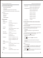
Contents
Chapter 1 Conception … … … … … … … … … … … … … … … … … … … … … 1
Chapter 2 BPQ CAT-5 System ………………………………………………… 1
Section 1
BPQ CAT-5 System Introduction ……………………………… 1
Section 2
BPQ CAT-5 System Outdoor Camera ………………………… 3
Chapter 3
System Setup … … … … … … … … … … … … … … … … … … … … 4
Section 1
Outdoor camera BPQ-888-IS LCD setup … … … … … … … 4
Section 2
Outdoor camera BPQ-881I/II/III setup … … … … … … … … 6
Section 3
Indoor monitor location encoding setup … … … … … … … 7
Section 4
Fence Machine Unlock Setup … … … … … … … … … … … 8
Chapter 4
System Installation Cautions … … … … … … … … … … … … … 9
Chapter 5
Common Fault Handling Methods … … … … … … … … … … … 13
Chapter 6
BPQ CAT-5C Management Center ……………………………… 14
Chapter 7
Indoor Monitor … … … … … … … … … … … … … … … … … … … 18
Chapter 8 Instruction of concentrator ……………………………………… 27
Chapter 9 Power Supply … … … … … … … … … … … … … … … … … … … … 29
Chapter 10
Technical Support and Service … … … … … … … … … … … … 29
Chapter 11 Other Instructions … … … … … … … … … … … … … … … … … … 30
Building system video door phone operation guides
Chapter 1 Conception
Ⅰ Building system video door phone and its project
Building system video door phone is the integrated equipment which is installed in
residential area, unit buildings, office buildings and other buildings. With the function of
identifying visitors by pictures and voice, controlling door release and sending help
messages to management center when encountering emergency situations, and the
management center can also release information to the residents.
Building system video door phone project is the process that combines and adjusts
the building system video door phone by the means of cable transmission according to the
relevant requirement of the weak current and the security project.
Ⅱ How to process the building system video door phone
ⅰ First of all, try to know clearly the performance, specification and installation
methods of all the equipments in the building system video door phone.
ⅱ Select the model and configuration for the system equipment according to the actual
situation and expected function requirements of building or the complex.
ⅲ Check and correct the layout and the electric environment of the building or the
complex according to the configuration and installation requirements.
ⅳ Install and adjust the system according to the installation instruction and relevant
process standard until it is acceptance.
Chapter 2 BPQ CAT-5 System
Section 1
BPQ CAT-5 System Introduction
Our smart building system video door phone is made up of outdoor camera, indoor
monitor, management center, decoder and other auxiliary equipments. Our outdoor
camera (BPQ CAT-5) has kinds of model and function for your option according to your
demands.
System function and character
·with a maximum capacity of 9999 indoor extensions
·Touch button/button, LCD/LED display for option
1
Building system video door phone operation guides
Building system video door phone operation guides
·CCD camera with night vision
brown, brown white, green, green white, blue, blue white, orange, orange white
·Controlled by the microcomputer, with simple circuit and powerful function
7p red
connect with the orange of net cable
·Soft program and decoding way without the influence of building structure
7p yellow
connect with the green white of net cable
·Bus line to the residents, fool style connection, short circuit won't affect the whole
7p green
connect with the green of net cable
system
7p white
connect with the blue and blue white of net cable
·Unlock with password (optional)
7p black
connect with the orange white and metal of net cable
·IC/ID card unlock(outdoor camera with entrance control function)
7p brown
connect with the brown of net cable
·Video and audio compatible, duplex intercom
7p orange
connect with the brown white of net cable
·Publish Chinese and English message
All the 7p plugs in the residential area wiring connection refers to above methods
·Networking function
(Note: red of 7p is power positive (+) and black of 7p is power negative (-).)
BPQ CAT-5 Building video door phone networking connection diagram
Make network crystal jack as below in order: :
Orange white, Orange, Green white, Blue, Blue white, Green, Brown white, Brown
To up floor
Indoor monitor
To up floor
Indoor monitor
Indoor monitor
Orange white
Orange
Green white
Blue
Blue white
Green
Brown white
Brown
Indoor monitor
network cable
network cable
Indoor monitor
Indoor monitor
Indoor monitor
network cable
Indoor monitor
network cable
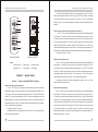
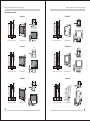
Section 2
Indoor monitor
Indoor monitor
Indoor monitor
Decoder
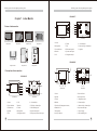
BPQ CAT-5 System Outdoor Camera
Indoor monitor
Decoder
6
6
2
Indoor monitor
Indoor monitor
Indoor monitor
Power supply
Power supply
Electronic Lock
Electronic Lock
2
Indoor monitor
3
Concentrator
Unit outdoor camera
使用说明
1. 输入住户房号,后按“#”键,本机示“CALL”,
并听到回铃声,等候通话开锁。
2. 若按错房号,请按“*”键消除,重新输入。
3. 小区联网系统按“1000”按“#”呼叫管理中心。
3
Unit outdoor camera
Power supply
1A
2B
3C
4D
5E
6F
1A
2B
3C
4D
5E
7G
8H
6F
9I
7G
8H
9I
*
0J
#
*
0J
#
4
4
Electronic Lock
Fence machine
Management center
5
RD
CA
1
5
RD
CA
1
BPQ-887 wiring instructions:
The cable is made up of 4 twisted pair and metal shielded pair, the colors are
2
Model:BPQ-881-IS LCD
Model:BPQ-881-IS LED
3
Building system video door phone operation guides
Building system video door phone operation guides
(2) Delete unlock password: Enter into main setting interface, press “8” to select
delete unlock password, then press “#” button, input “5555”(the outdoor unit display
1111), outdoor camera shows setting success. Then press “*” return to main setting
6
2
2
5
interface. (Note: If you use delete password, all outdoor camera unlock password are
deleted.)
3
1
3
Outdoor camera unit number setup (Such as unit 1, block 11)
1.
1
2
3
*
4
5
6
0
7
8
9
#
2
3
4
5
6
7
8
9
*
0
#
1
4
Press “*” & “#” on outdoor camera at the same time until screen display existing
block number. The outdoor camera enter into setting interface and press “2”(up) or
4
“8”(down) to select block number setting, then press “#” . Input “9027” after hear sound of
“DI”.(note: the screen display 1111 now). The outdoor camera enters into block number
setting. Then input any three numbers from 001 to 199 and press “#” to confirm. The
5
1
6
outdoor camera display operation success. Press “*” return to main setting interface. (The
first and second number means block number and the third number means unit number.)
2. If input wrong, press “*” to return.
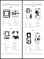
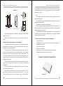
Model: BPQ-881B/C/III
Model: BPQ-881B/C/I
Outdoor camera location setup
Notes:
1.Press “*” & “#” on the outdoor camera at the same time until screen display existing
1. Access control
2. Camera lens
3. Display screen
block number. The outdoor camera enter into setting interface and press “2”(up) or
4. Digital button
5. Loud speaker
6. Microphone
“8”(down) to select monitor serial number setting, then press “#”. Input “7777” after hear
sound of “DI”.(note: the screen display 1111 now). The outdoor camera enters into monitor
Chapter 3
Section 1
System Setup
Outdoor camera BPQ-888-IS LCD setup
serial number setting. Then input “from 1 to 4” and press “#” to confirm. The outdoor
camera display operation success. Press “*” return to main setting interface.
2.If there are two unit door in two different entrance of one block, Use “1” or ”2” to be
on half of different unit door, an so on.
Outdoor camera password unlock setup
1. Press “*” & “#” button on the outdoor camera at the same time until screen display
Indoor monitor check setting
existing block number. The outdoor camera enter into setting interface and press “2”(up)
Press “*” & “#” on the outdoor camera at the same time until screen display existing
or “8”(down) to select unlock password setting, then press “#” . Input “8888” after hear
block number. The outdoor camera enter into setting interface and press “2”(up) or
sound of “DI”.(note: the screen display 1111 now). The outdoor camera enter into unlock
“8”(down) to select indoor camera check setting, then press “#”. Input “6666” after hear
password setting. Then input any three numbers from 001 to 120 add 4 digital user
sound of “DI”.(note: the screen display 1111 now). The outdoor camera enters into indoor
password and press “#” button. The outdoor camera shows password setup is finished.
monitor check setting. Then input “from 01 to 99” start floors and press “#” to confirm, then
Press “*” return to main setting interface.
input “from 01 to 99” stop floors and press “#” to confirm. Input stat room number, press
2. If input wrong, press “*” to return.
“#”to confirm and input stop room number, press “#” to confirm. The outdoor camera
(1) Password unlock: User password unlock: #+XXX (001-120 for option)XXX(four
displays check situation. It will return to main setting interface after finish checking. If do
user password) (7 number total)
4
not want to check, press “*” to return.
5
Building system video door phone operation guides
Indoor monitor check setting
Press “*” & “#” on the outdoor camera at the same time until screen display existing
block number. The outdoor camera enter into setting interface and press “2”(up) or
“8”(down) to select indoor camera check setting, then press “#”. Input “6666” after hear
sound of “DI”.(note: the screen display 1111 now). The outdoor camera enters into indoor
monitor check setting. Then input “from 01 to 99” start floors and press “#” to confirm, then
input “from 01 to 99” stop floors and press “#” to confirm. Input stat room number, press
“#”to confirm and input stop room number, press “#” to confirm. The outdoor camera
displays check situation. It will return to main setting interface after finish checking. If do
not want to check, press “*” to return.
Building system video door phone operation guides
(The first and second number means block number and the third number means unit
number. Then press “#” button and screen will display “CALL”, “FALL”, “OPEN” until light
off, it means the outdoor camera location encoding password setup is finished.)
Outdoor camera location setup
Press '*”& “#” buttons on the outdoor camera at the same time, then power on outdoor
camera.(about 3 seconds) Release your hand when hear the sound of “DI”. Then repress
“#” and will hear the sound of “DI”. Input “7777” (the screen display “1111” now) and screen
will display nothing means enter into outdoor camera location setup status. Next, press “#”
after input “1” (1-4 for option). Then finish the outdoor camera location setup.
If there are two unit door in two different entrance of one block, Use “1” or ”2” to be on
half of different unit door, an so on.
Section 2 Outdoor camera BPQ-881I/II/III setup
Operation of outdoor camera
1.Call indoor monitor: Input two block number and two room number of household. If
Outdoor camera password unlock setup
Step1. Under power on status, press “*” & “#” button on the outdoor camera at the
same time until screen display “CALL”, FALL”, OPEN” and existing block number in order.
Step2. Press “#” button immediately after hear the sound of “DI”. Input “8888”(note:
the screen display nothing now.) to enter into setting interface. Input random three number
among “001 to 120” (These three numbers is the serial number of later input password.).
Then press “#” button and input four numbers for password. Press “#” to finish outdoor
camera password setup.
Step3. Password unlock
User password unlock: #+XXXX (four digital password)
How to delete outdoor camera unlock password
Under power on status, press “*” & “#” button on the outdoor camera at the same time
dial wrong, press”*” to clean and redial. If indoor monitor exist, outdoor unit has back
ringing, related indoor monitor make a ringing. If the indoor monitor answers, the back
ringing of outdoor camera will stop. They start intercom about 60 seconds and hang up
automatically. If no answer, it will hang up automatically after 30 seconds. If dialed number
be cleaned automatically, it means the number is over this machine encode range. If the
numbers are dialed but there is no back ringing, that means this indoor camera is not exist
or has problem.
2.password unlock: Press “#” button first, then input 4 number of password.
3.IC/ID card unlock: Put IC/ID card close to induction window, if the card is authorized
card, the outdoor camera will sound “DI” and unlock. If the card is not authorized, the
outdoor camera will sound “DI” 3 times. (The outdoor camera need install access control
module.)
until screen display “OPEN” and existing block number. Press “#” button immediately after
hear the sound of “DI”. Input “8888”(note: the screen display “1111” now.). Then press
“#+128”, next to press “#+8888” until screen display “OPEN” and existing block number. It
Section 3 Indoor monitor location encoding setup
means the password of outdoor camera unlock is delete successfully. (Note: This
operation will delete all the previous unlock password.)
1. Well connect indoor monitor, open the cap of “SET” and press set button about 3
seconds. The indoor monitor indicate light is on after flash. Then press four room number +
Outdoor camera unit encoding setup
“# " on the outdoor camera and exit by press “*” button after hear the sound of "DU DU". It
Press “*” & “#” button on the outdoor camera at the same time until screen display
means F1 indoor monitor location setup success. The same steps for F2, F3 and F4. (note:
“CALL”, FALL”, OPEN” and existing block number in order. Press “#” button immediately.
do not exchange indoor monitor port or power off in the operation process. The setup
Input “9027” after hear the sound of “DI”.(note: the screen display all is “1” now.) to enter
should finish within 10 seconds since release the “set” button. Otherwise, the system will
into outdoor camera location encoding setting interface. Input “111” and press “#” button.
auto exit and be in standby situation.) Put the cap after 4 indoor monitors location setting
6
7
Building system video door phone operation guides
Building system video door phone operation guides
finish.
order and existing building number, please release press button.)
The next decoder is the same setting method as above. But you can not set the same
room number for different floors.
Step 2 Press “#” at once, input”9027” when hear sound of “DI” (Note: There is four
1111 display on screen.). If there is nothing shown on screen, it means enter into fence
For example, room number 0201(press “0201+”#” on the outdoor camera, and press
“*” after hear the sound of “DU DU”)
machine location setting status, input “XXX” and press “#” (001-250 for option), then finish
the fence machine location setting. (Note: The fence machine location code can not set as
2. The previous data will be auto covered by new setted location code. (Ref the below
alarm number of 110.)
picture)
light
IN
SET
F1
F2
F3
light
IN
F4 OUT
F1
Chapter 4 System Installation Cautions
SET
F2
F3
F4 OUT
Installation adjustment and common faults handling:
1) Please set up outdoor camera number, then set up decoder floor and room number.
outdoor camera
power
2) There's a volume knob on the system board, do not adjust the volume too loud in
case that it makes Whistler. There's a volume limitation of this system indoor monitor, do
not try to adjust it lead to damage the knob.
left: F1:Indoor monitor1 F2:Indoor monitor2 F3:Indoor monitor3 F4:Indoor monitor4
right: F1:Indoor monitor5 F2:Indoor monitor6 F3:Indoor monitor7 F4:Indoor monitor8
3) The wiring connection should be completely correct, otherwise, it will lead the
whole system. The wrong connection of the bus line may bring all of the indoor monitors in
the building into failing to ring the bell. When encountering the above situation, please
power off most of the floor protectors, and check one by one until you find out the fault.
Section 4
Fence Machine Unlock Setup
4) When the outdoor camera calls the indoor monitor, if the outdoor camera display
“CALL” and stop there, it means the bus line cut off or the yellow line is open circuit. If there
Fence Machine Unlock Setup
is no bell ring, it means it fails to detect the indoor monitor. The reason may be the address
Step 1 Press “*” & “#” button on the outdoor camera at the same time, power on fence
code of the outdoor camera does not match with that of the indoor monitor. If it's abnormal
machine (about 3 seconds). When you hear sound of “DI”, then release, next press “#” & “*”
or has no voice when the outdoor camera calls all the indoor monitors, maybe there's some
key immediately (method 2: Under power on status, press “*” & “#” & reset button on main
wrong with the bus line.
board, then release when hear sound of “DI”)
Step 2 Press”#” at once, when hear sound of “DI” ( Note: There is nothing show on
screen at this time), it means enter into fence machine password setup status, input
“XXXX” four digital one time, then press “#” to finished fence machine password setting.
Outdoor camera installation
(1)
Installation on the door
In the unit door, on the fixed side in general, choose a proper position and drill a
Step 2 Password unlock
installation hole, decide the size according to the outdoor station selected. The distance
User password unlock: #+xxxx (four digital password)
between the ground level and the bottom of the outdoor camera is approximately 135cm.
Hole (1) use the Wafer head Self tapping screw (M3X6) to fix the seal, and then get the
Fence machine location encode method setup
Step 1 Press '*”& “#” on the outdoor camera at the same time, power on outdoor
camera (about 3 seconds). When you hear sound of “DI”, then loosen (method 2: Under
power on status, press “*” & “#”, when outdoor camera show “CALL”, “FALL”, “OPEN” in
8
rear cover well fixed by using the self tapping screws (M3X6) according to the direction of
the arrow. Fix the door accessories on the hole (2) by using the self tapping screws.
At last, make an iron box with size of 133*313*38mm, flanging the surroundings and
fix it on the hole of the iron door, to avoid of man made destruction.
9
Building system video door phone operation guides
As below picture shows:
Building system video door phone operation guides
Wall mounting
Drill a hole in the wall according to the below picture, then tuck in the colloidal particle,
133mm
Fix the rear cover to the wall by using the self tapping screw (M3X6), Fix it tight as the arrow
direction shows, use two self tapping screws (M3X20) fix it. The installation of outdoor
camera is shows as below picture.
313mm
Screw holes position
these two gaps should
be displayed in the wall
1A
4D
7G
(1)
*
2B
5E
8H
0J
3C
6F
9I
#
CARD
The iron box is show as the below picture.
Notice: Different type outdoor unit has different installation size and method
Standard Height of Outdoor Camera Installation
78
De
gre
eA
ng
le
1500mm
Lens centre
500mm
(2) Installation on the wall
Make a slot in the proper position of the wall, the size is the same as installation on the
door (as above). The distance between the ground level and the bottom of the outdoor
camera is approximately 135cm. Then put the embedded box into the slot and fix it, take
care of the depth adjustment.
Wiring requirements:
1. All cables of system is adapts twisted shielded networking cable, the sectional area
is equal or more than 0.52 square millimeter.
2.The sectional area of cable from power to outdoor camera and from outdoor camera
to electric lock should be equal or more than 1 square millimeter, and the length shouldn't
be more than 15m, otherwise must enlarge the cable sectional area.
10
11
Building system video door phone operation guides
Building system video door phone operation guides
System installation cautions:
·Please install outdoor camera in good visual level, supposed to be 150cm.(The
Chapter 5 Common Fault Handling Methods
height of camera lens)
·Don't install video intercom system in the following places: direct sunlight, high
temperature, snow, moisture, chemical corrosion and dusty place. (Standard
1.
temperature is 0-45℃)
Fault coverage: unlock circuit
·Far away from the places where strong magnetic field or magnetic interference.
· Select shielded twisted pair CAT 6 for all the networking system, about shielding
layer, select metal weave net.
Can not unlock
Fault remove and analysis
a) Check the line from outdoor camera to electronic lock
b) Check L+, L- whether has about 12V voltage output to electronic lock or not
·Shielding layer should well connected with system and handle well GND.
c) Check electronic lock coil is damaged or not
· Better to connect the system in series , select the iron pipe for the wiring pipe as far
2. Image flapping up and down
as possible, both ends of iron pipe have to be connect to the ground . And keep a distance of
Fault coverage: indoor monitor video circuit
up to 50cm with high voltage cables (Such as, AC 220V, elevator wire, wired television etc)
Fault analysis: Frame is not synchronism, adjust the potentiometer.
to improve anti-jamming and lightning protection ability.
· For system stable and maintenance convenient, all networking connection joint
cannot be put inside pipe or wet place, solder joint should be handled, and packed with
heat shrinkable tube, avoid of water and wet in order to make the system stable and check
it conveniently.
·In outdoor unit wiring entrance should consider connect drip line.
· Do not be installed at a place where noise is over 65dB, otherwise, the noise from
handset of indoor unit will be loud.
3. Outdoor camera can not call indoor monitor
Fault coverage: Decoding part
Fault analysis: Press indoor monitor “monitor” button to check whether can monitor
the outside of outdoor camera or not.
If can, the last four number of indoor camera set is wrong.
If can not, the first three number of indoor monitor room number is wrong or circuit
problem.
4. Have image, no voice
·Don't operate with power during installation.
Fault coverage: intercom line
·After all wires connected, check again and make sure that there is no mistakes then
Fault analysis: confirm is one unit or whole units
you can operate the system.
·When power on, if system is in abnormal situation. Please cut off power at once until
problem solved.
· If system is not normal, cut off the power and check the system part by part
according to <simple troubleshooting>. If cannot check out the problem, please inform
Whole units:
a) Check outdoor camera
b) Outdoor camera intercom circuit
One unit: check indoor monitor
5. Monitor no image
agent or after-sale service department, do not repair by yourself and change parts due to
Fault coverage: video parts
system damage
Fault analysis: whether can intercom and image
·Before you use the IC or ID card for the first time on the outdoor camera with access
control, you should register in the management center.
If can, set up outdoor camera location
If can not, CCD is damaged
6. Outdoor camera display “CALL” and button out of work
Fault coverage: system power
Yellow line of bus line is broken
12
13
Building system video door phone operation guides
Building system video door phone operation guides
3.Technical data
Chapter 6
BPQ CAT-5C Management Center
R F I D
3
1
2
4
5
7
8
*
Type: BPQ CAT-5C
Environment temperature: -20℃-60℃
æaterial: ABS plastic
Input voltage: DC12-18V/2A
Screen size:7” TFT or 4” LCD screen
Standby current: ≤100mA
Resolution: 480x320
Working current: ≤450mA
Contrast: 400:1
Maxi. Output power: ≤6.5W
Brightness: 300cd/m2
Distortion: ≤7%
Operation method: press button
Size:360x210x73mm
6
0
9
Intercom method: Pick up handset receiver
#
4.Operation instruction
1. Management center front and rear instruction
Recognize LCD display
13
14 15 16
3
3
8
1
7
R F I D
2
4
5
7
8
*
2
6
0
6
1. Handset receiver
The previous three numbers are block numbers, the latter four numbers are floor
9
10
3
1
9
and room numbers.
#
12 11 3 4 5
7. LCD screen
13. RJ 45 Jack
2. Card read area
8. Screen
14. RS232 Jack
3. Volume adjust
9. Check
15. Power
4. Color saturation adjust
10. Up
5. Brightness adjust
11. Down
6. Number keys
16. Switch
12. Unlock
Unit number
Room number
(management centre call indoor monitor)
Unit numbers
0000
(management center call outdoor camera)
3
Unit number
3
Room number (Indoor monitor call management centre,
management centre display)
Unit number
0000
(Outdoor camera call management centre,
management centre display)
Call function
2.Function and features
·Call outdoor camera, fence machine, intercom, monitor, unlock function
·Call and intercom with little area
·English menu operation, store 32 latest alarm number
·With R232 serial port for computer controller manage alarm message, monthly
print4
Management centre can call indoor monitor, monitor outdoor camera and other
fence machines.
A. Management centre call indoor monitor
If the unit system of be called indoor monitor is free (not busy), input unit and room
numbers of this indoor monitor on the management center. (total is 7 numbers). Then
press “#” button, the management centre video will be open. Meanwhile, the indoor
monitor is ring on and video is opened. In this case, both of management center or
indoor monitor can off-hook and intercom each other.
14
15
Building system video door phone operation guides
Unit number +Room number
+ #+Off-hook
Management center
Building system video door phone operation guides
Duplex intercom
Off-hook
Indoor monitor monitor
management center
Indoor monitor
If the unit system of be called indoor monitor is busy, it's no use for management centre
to call this indoor monitor.
Store alarm number function
Management center can store latest 32 alarm number (Alert)
Review alarm number function
Pressing “check” button first, then press “up or down” to look up all the stored alarming
B. Management center monitor outdoor camera:
numbers.
If the outdoor camera be called is free (not busy), input unit number and “0000” on the
management center (total is 7 numbers). Then press “#” button, the management centre
Delete alarm numbers function
screen open and display outdoor camera image. Meanwhile, the management can off-
Press “Delete” button to delete displayed alarm number.
hook and intercom with outdoor camera. And press “unlock” button to open the lock of
called outdoor camera.
Alert indicator function
If there are many multifunctional alarm indoor monitors in the system, the probe will
Duplex intercom, display
outdoor camera outside image
Unit number+0000+#+Off-hook
Outdoor camera
Press “unlock” to open the lock
of the called outdoor camera
send alert signal to management centre after activated. And management center not only
display indoor monitor number, but also “infrared” “door contact” “smoke” “gas” and “alert
protection”.
If called outdoor camera is working, it is no use for management centre to call it.
Be called function
Connect with computer function
Management centre can be called by indoor monitor, outdoor camera and fence
With R232 serial port for computer controller manage alarm message, monthly print.
machine in one system.
A.Indoor monitor call management center
Volume adjustment function
Under hang-up status, press “call” button of indoor monitor, management centre will
When management center intercom with outdoor camera or indoor monitor, revolve
display its unit and room numbers, and ring “Ding-Dong” sound. If management center is
the volume adjust knob to adjust hand-free volume.
free, it can intercom with indoor monitor after off-hooking. And indoor monitor screen
display white. If system is busy, the indoor monitor only can send code signal to
Brightness adjust function
management center.
When management center display image normally, revolve brightness adjust knob to
adjust the image brightness.
Call button+ Off-hook
Indoor monitor
Duplex intercom
Off-hook
Indoor monitor displaymanagement Management center
center outside image
Contrast adjust function
When management centre displays outdoor camera image normally, revolve
B.Outdoor camera call management center
contrast adjust knob to adjust the image contrast.
Input “1000” on outdoor camera, then press “#” button to call management center (If it
is direct-press outdoor camera, press “management centre” button.). The management
center will display unit number of outdoor camera + “0000” and ring a sound of “DingDong”. If the management center is free, it can make intercom with outdoor camera after
off-hook. Meanwhile the outdoor camera outside image is displayed on management
center screen, and press “unlock” button to open the lock of calling outdoor camera.
16
17
Building system video door phone operation guides
Chapter 7
Building system video door phone operation guides
BPQ-882CT7
Indoor Monitor
Pictures of indoor monitor
2
3
4
5
6
7
1
8
9
10
11
12
(Front face)
BPQ-882CL7
BPQ-882CQ7
BPQ-882CT7
BPQ-882CU7
1. Screen
13
(Fear face)
6. Unlock
11. Contrast adjust
2. Microphone
7. Talk
12. Intercom/ring volume adjust
3. Power indicator
8. Wall mounting hole
13. Speaker
4. Monitor
9. System connect port
5. Call
10. Brightness adjust
BPQ-882CQ7
BPQ-882CK43
BPQ-882CS4
BPQ-882CF4
1. Description of indoor monitors
9
8
1
2
4
5
6
7
8
9
2
3
3 4
14
(Front face)
18
7
13
10
11
12
5
6
(Front face)
15
(Fear face)
16
11
12
13
BPQ-882CL7
1
10
1.Screen
14 15
(Fear face)
9. Power indicator
2.Speaker
10.DC input socket
3.Unlock
11. Brightness adjust
1. Screen
6. Call
11. Contrast adjust
4.Monitor
12. Contrast adjust
2. Power indicator
7. Monitor
12. Talk/ring volume adjust
5.Function( Call management center)
13. Intercom/ring volume adjust
3.Talk indicator
8. Unlock
13. Wall mounting hole
6.Handfree/Call
14.System connect port
4. Speaker
9. Microphone
14. System connect port
7. Microphone
15. Power supply
5. Talk
10. Brightness adjust
15. Emergency button connect port
8.Activity indicator
16. Wall mounting hole
19
Building system video door phone operation guides
Building system video door phone operation guides
BPQ-882CS4
BPQ-882CU7
3
4
5
6
7
8
9
1
2
1
8
13
10
11
12
13
14
15
(Front face)
14
7
6
5
4
3
2
(Fear face)
1. Screen
6. Talk
2. Speaker
12
11 10 9
11.Contrast adjust
7. Monitor
(Front face)
12.Brightness adjust
3. Microphone
8. Unlock
13.Intercom/ring volume adjust
4. Power indicator
9.Microphone
14. System connect port
5. Call
10. Wall mounting hole
15. Emergency button connect port
BPQ-882CK43
(Fear face)
6. Call
11. Brightness adjust
2. Microphone
7. Power indicator
12. Wall mounting hole
3. Talk
8. Speaker
13. System connect port
4. Unlock
9. Intercom/ring volume adjust
14. Emergency button connect port
5. Monitor
10. Contrast adjust
1. Screen
BPQ-882CF4
10
1
1
8
9
14
15
2
3
4
5
6
7
(Front face)
(Fear face)
1.Screen
9.Activity indicator
2.Speaker
10.Wall mounting hole
3.Unlock
11.Intercom/ring volume adjust
4.Monitor
12. Brightness adjust
2
3
4
8
5
7
6
(Front face)
1. Screen
13
14
9
10
11
6. Microphone
(Fear face)
11. Brightness adjust
5.Function(Call manager center)
13. Contrast adjust
2. Speaker
7. Talk
12. Wall mounting hole
6.Handfree/call
14. System connect port
3. Monitor
8. Power indicator
13. System connect port
7.Micorphone
15. Emergency button connect port
4. Unlock
9. Intercom/ring volume adjust
14. Emergency button connect port
5. Call
10. Contrast adjust
8.Power indicator
20
11 12 13
12
21
Building system video door phone operation guides
2. Function and feature of all indoor monitors
Building system video door phone operation guides
BPQ-882CL7:12 melodies, BPQ-882CK43:16 melodies,
Operation method:
BPQ-882CF4:12 melodies, BPQ-882CS4:12 melodies
·Monitor outdoor camera outside image
Outward appearance size: BPQ-882CT7:touch button, BPQ-882CU7: button,
·Call manage center
·Accept outdoor camera, management center, fence machine calling
BPQ-882CL7:button, BPQ-882CK43:button,
· Hold conversation with outdoor camera, fence machine, control outdoor camera
BPQ-882CF4:button, BPQ-882CS4:button
BPQ-882CT7: 215x140x18mm,
electronic lock
BPQ-882CU7: 238x146x23mm,
·Accept four defense zone
·Buttons removal
BPQ-882CL7: 229x164x33mm,
·Message sink
BPQ-882CK43: 156x108x21mm,
BPQ-882CF4: 133x208x28mm,
·Chinese menu operation )
BPQ-882CS4: 191x213x51mm
3.Technical parameter:
Material:
4. Operation method: (Note: All indoor monitors are the same as below)
Working temperature:
All is -10℃-60℃
Screen size:
BPQ-882CT7\ BPQ-882CU7\ BPQ-882CL7 (7”);
1) Installation fix:
BPQ-882CK43 (4.3”);
Firstly fix the wall mounting bracket on the wall, then well connect with system, and put
Input voltage:
All is DC12-18V/2A
indoor monitor on the bracket last.
Note: The room number has been set up by the local dealer or project dealer. If need
Resolution:
BPQ-882CT7\BPQ-882CU7\BPQ-882CL7 is 480x320;
modify it, please consult estate management, local dealer or project dealer.
BPQ-882CF4\BPQ-882CS4 (4”).
BPQ-882CK43 is480x272;
BPQ-882CF4\BPQ-882CS4 is480x234.
Standby current:
All is ≤3mA
Wide and height ratio:
BPQ-882CT7,BPQ-882CU7,BPQ-882CL7,
BPQ-882CK43 is16:9;
Working current:
Contrast:
After hear the sound of “Ding Dong” , press “
” button to talk with visitor.
3) Unlock:
When visitor call the user, the user can talk with visitors by press “
”after hear the
sound of “Ding Dong”, and press “
”button to unlock for visitor.
Note: The door can not be unlocked without user answer.
BPQ-882CF\BPQ-882CS4 is 4:3
4) Melody select:
Press “
BPQ-882CL7:≤150mA; BPQ-882CK43: ≤120mA;
5) Volume adjust:
”button first, then press “
”button to select melody.
BPQ-882CF4: ≤130mA; BPQ-882CS4: ≤120mA
Users can revolve the volume potentiometer adjust intercom and ring volume.
All is 400:1
6) Image adjust:
BPQ-882CT7, BPQ-882CU7, BPQ-882CL7 is 300cd/m2,
Users can revolve the brightness and contrast potentiometer to adjust the definition
of image.
BPQ-882CK43 is 220cd/m2,
7) Call management center:
BPQ-882CF4, BPQ-882CS4 is 250cd/m2
Users press “
Distortion:
All is ≤7%
Installation method:
All is wall mounting
Melody:
2) Users answer:
BPQ-882CT7: ≤150mA; BPQ-882CU7: ≤160mA;
The Maximum output power: All is ≤5W
Brightness:
22
All is hand free
Intercom method:
All is ABS plastic
BPQ-882CT7:16 melodies, BPQ-882CU7:12 melodies,
”button to call management center, management can pick up
handset to talk with users. (Note: This function is useful only the system is networking.)
6) Monitoring outdoor camera
Users press “
”button to monitor outdoor camera outside image and press it again
to stop. (The image will auto shut down 15seconds later.)
23
Building system video door phone operation guides
Building system video door phone operation guides
5. Installation instruction
BPQ-882CL7
BPQ-882CU7
6c m
6cm
wall mounting bracket
screen center
23.8cm
3c
m
wall mounting bracket
50cm
outward appearance size
Standard height of indoor monitor
Standard height of indoor monitor
BPQ-882CT7
outward appearance size
BPQ-882CK43
6.2cm
2.1cm
screen center
screen center
15.6cm
10.8cm
14cm
wall mounting bracket
145c m - 160c m
1.8cm
145cm-160cm
21.5cm
outward appearance size
Standard height of indoor monitor
BPQ-882CQ7
outward appearance size
BPQ-882CS4
6cm
2.4cm
15.7cm
145cm-160cm
23.7c m
wall mounting bracket
50cm
3cm
screen center
cm
19.1
5.1
cm
21.3cm
screen center
145cm-160cm
3cm
6cm
24
wall mounting bracket
50cm
50cm
Standard height of indoor monitor
Standard height of indoor monitor
8.3cm
6cm
8.3cm
50cm
2.
14.6cm
16.4cm
1 4 5c m - 1 60 cm
22.9cm
1 4 5c m - 1 60 cm
3 cm
3.3cm
screen center
50cm
outward appearance size
Standard height of indoor monitor
outward appearance size
25
Building system video door phone operation guides
Building system video door phone operation guides
(" 0 " is set)→press “monitor” button 8 times)→press “unlock” button (number " 8 " is set)→
BPQ-882CF4
press “unlock” button (number " 0 " is set)→press “monitor” button 1 time→press “unlock”
5.7cm
screen center
8cm
button (number " 1 " is set)。
2.8cm
13.3cm
Notes:
1 4 5c m - 1 60 cm
1、 Press button one time, the status indicator on and off one time. It means the each
20.8cm
wall mounting bracket
pressing of button is efficient.
2、The time between two pressing of button should less than 10seconds, otherwise, it will
return to static state automatically.
3. The new location code will auto coverage the old ones.
4. If the system is not networking, the block number is default as 111. The first unit of one
5 0cm
Standard height of indoor monitor
Standard height of indoor monitor
block, the unit number is 1. The second unit of one block, the unit number is 2. The third unit of
one block, the unit number is 3, and so on.
5. The all of 7 numbers of location codes should be input, otherwise, the location code is
(1) Fix the wall mounting bracket on the wall with 3 self tapping screws at the standard
height of 145-160cm.
not validity. If you quit in the midway, the numbers that set are not validity. The default
location code of indoor unit is “1111111”.
(2) Insert the connector on the back of indoor monitor and put indoor monitor on the
bracket.
7. The indoor monitor should far away the following places:
·Direct sunlight shooting
6. Setup of indoor monitor location code (room number)
1.Under standby situation with power on, press “unlock” button about 5 seconds, the
status indicator is not on first, then it will flash 2 times and off, release “unlock” button. It
means enter into room number setup status.
2. The 7 numbers of location codes is auto start from block number (the first one). The
“monitor” button is counting button. Press it one time means number “1”, press it two time
·High temperature or low temperature environment(standard temperature0-45℃)
·Leaking or moist environment
·Dust or air pollution serious
·Back noise more than 65dB
·Strong magnetic field (such as near loud speaker without shielding)
·Electromagnetic interference serious (such as motor)
means number “2”, and so on. If do not press “monitor” button, it means number “0”. The
“unlock” button is confirm button. Please press “unlock” button one time after press
“monitor” button to confirm number value, now the line busy indicator flash 2 seconds, it
Chapter 8 Instruction of concentrator
means this code is confirmed.
3. When you finish the location code setup, the status indicator will auto flash 5 times
and on long time. It means that the setting is success and return to standby status
automatically.
For example: the location code is 0680801(It means block 6, unit 8, room number
0801). Please setup as below steps.
Press “unlock” button about 5 seconds→press “unlock” button (number " 0 " is set)→
press “monitor” button 6 times→ press “unlock” button (number " 6 " is set)→ press
“monitor” button 8 times→ press” unlock” button (number " 8 " is set)→ press “unlock button
26
Concentrator
27
Building system video door phone operation guides
Building system video door phone operation guides
Plane graph
Connect graph
J1
J2
J3
J4
IN
主机1 主机2 主机3 主机4
J2
J3
J4
IN
J2
J3
J4
1. Picture of power supply
DC18V电源
J1
J1
Chapter 9 Power Supply
DC18V电源
18DCVpower
IN
主机5 主机6 主机7
LED
management
center
short circuit needle
J1:outdoor unit
J2:outdoor unit
J3:outdoor unit
J4:outdoor unit
J2:outdoor unit
J3:outdoor unit
J4:outdoor unit
Wiring of concentrator
Wiring instruction
1
2
3
4
5
6
7
2. Specifications:
metal
metal
Input Voltage: AC 220-240V
Output Voltage: DC 12-18V
metal
metal
Working Temperature: -20~60℃
(1)White yellow line: connect with electric control or electromagnetic lock
yellow
Protection Rate: IP33
white(+)
white
no polarity
电控锁2芯对应接头
yellow(-)
have polarity
磁力锁2芯对应接头
(2) Red black line: connect with power
red(+)
black(-)
have polarity
1.IN Port:
Connect with bus line, the port of J1, J2, J3, J4 connect with outdoor unit and fence
machine.
2.If need 2 or more concentrators, it can connect in serial.
Method: Take one port among of J1, J2, J3,J4 of the concentrator that connect with
management center as output port for next concentrator. And it is the similar way for more
concentrator connection.
The management center has been setup before delivery.
If need down load concentrator data, please visit our company website of
www.szauskay.com to down load.
28
Output Power: 50W
Chapter 10 Technical Support and Service
1.“Auskay” products insist on pre-sale, sale, after-sale service policy in the whole
process. Before confirm the project solution, please read this manual instruction
carefully, then consult and confirm with technical person of our branch office or agent,
large area networking or special project can consult directly with head office technical
support center.
2.When install and adjustment these products, please conduct according to this
manual instruction strictly. If there is difficulty, please contact with our branch office or
agent. For special problem, please contact with our technical person of head office.
3.The explanation rights of this manual instruction is own to Shezhen Auskay Smart
Electricity Co., Ltd. Any question in the process of using on engineering guidance, please
call our market service center
4.Technical support hotline
Tel: +86-0755-89496513
Fax: +86-0755-89494542
29
Building system video door phone operation guides
Chapter 11 Other Instructions
Transportation:
This products should be transport in the condition of good package, do not transport
unpacked. Avoid of bBPQ, snow, dust and mechanical damage.
Store
Well packed products should stored in environment temperature of 10°C~40°C.
Relative humidity no more than 80%, no corrosive gas, ventilated indoor or warehouse.
Statement
Although our product is a kind of advanced alarm equipment, but if there is artificial
damage or system failure will influence system work. According to the alarm information
from this equipment, only can reduce suffer loss from theft, rob, fire, gas leak etc, but not
guarantee no mistake. Our company assume no responsibility of user's suffer loss from
theft, fire etc. for relative reason to claim for compensation from our company. The
maximum compensation limit is less than products prices.
30