1
User’s
Manual
AQ6150/AQ6151
Optical Wavelength Meter
IM AQ6150-01EN
1st Edition
Thank you for purchasing the AQ6150/AQ6151 Optical Wavelength Meter. The AQ6150/
AQ6151 is a high-speed wavelength measuring instrument for LD and LED light sources.
This user’s manual explains the features, operating procedures, and handling
precautions of the AQ6150/AQ6151.
To ensure correct use, please read this manual thoroughly before beginning operation.
Keep this manual in a safe place for quick reference in the event that a question arises.
The following manuals, including this one, are provided as manuals for the AQ6150/
AQ6151. Please read all manuals.
AQ6150/AQ6151
Manual Title
AQ6150/AQ6151
Optical Wavelength Meter
User’s Manual
AQ6150/AQ6151
Optical Wavelength Meter
Getting Started Guide
AQ6150/AQ6151
Optical Wavelength Meter
Remote Control
User’s Manual
Manual No.
IM AQ6150-01EN
IM AQ6150-02EN
IM AQ6150-17EN
Description
This manual. The manual explains all the
AQ6150/AQ6151 features other than the remote
control features.
Provided as a printed manual. This guide explains
the handling precautions, basic operations, and
specifications of the AQ6150/AQ6151.
This manual explains the AQ6150/AQ6151
communication interface features and how to use
them.
PDF files of all the manuals above are included in the accompanying CD.
Notes
Trademarks
Revisions
• The contents of this manual are subject to change without prior notice as a result
of continuing improvements to the instrument’s performance and functionality. The
figures given in this manual may differ from those that actually appear on your screen.
• Every effort has been made in the preparation of this manual to ensure the accuracy
of its contents. However, should you have any questions or find any errors, please
contact your nearest YOKOGAWA dealer.
• Copying or reproducing all or any part of the contents of this manual without the
permission of YOKOGAWA is strictly prohibited.
• Microsoft, Internet Explorer, MS-DOS, Windows, Windows NT, and Windows XP are
either registered trademarks or trademarks of Microsoft Corporation in the United
States and/or other countries.
• Adobe and Acrobat are either registered trademarks or trademarks of Adobe Systems
Incorporated.
• Ethernet is a registered trademark of Fuji Xerox Corporation.
• In this manual, the TM and ® symbols do not accompany their respective registered
trademark or trademark names.
• Other company and product names are registered trademarks or trademarks of their
respective holders.
• 1st Edition: December 2012
1st Edition : December 2012 (YMI)
All Rights Reserved, Copyright © 2012 Yokogawa Meters & Instruments Corporation
IM AQ6150-01EN
Safety Precautions
This instrument is an IEC safety class I instrument (provided with a terminal for protective
earth grounding).
The general safety precautions described herein must be observed during all phases
of operation. If the instrument is used in a manner not specified in this manual, the
protection provided by the instrument may be impaired. YOKOGAWA assumes no liability
for the customer’s failure to comply with these requirements.
The following symbols are used on this instrument.
Warning: handle with care. Refer to the user’s manual or service manual.
This symbol appears on dangerous locations on the instrument which require
special instructions for proper handling or use. The same symbol appears in the
corresponding place in the manual to identify those instructions.)
Alternating current
ON (power)
OFF (power)
ii
IM AQ6150-01EN
Conventions Used in This Manual
Notes
The notes and cautions in this manual are categorized using the following symbols.
Improper handling or use can lead to injury to the user or damage
to the instrument. This symbol appears on the instrument to indicate
that the user must refer to the user’s manual for special instructions.
The same symbol appears in the corresponding place in the user’s
manual to identify those instructions. In the user’s manual, the symbol
is used in conjunction with the word “WARNING” or “CAUTION.”
WARNING
Calls attention to actions or conditions that could cause serious or
fatal injury to the user, and precautions that can be taken to prevent
such occurrences.
CAUTION
Calls attention to actions or conditions that could cause light injury
to the user or cause damage to the instrument or user’s data, and
precautions that can be taken to prevent such occurrences.
Note
Calls attention to information that is important for proper operation of
the instrument.
Notations Used in the Procedural Explanations
The contents of the procedural explanations are indicated using the following symbols,
notations, and terminology.
Procedure
Carry out the procedure according to the step numbers. All
procedures are written under the assumption that you are starting
operation at the beginning of the procedure, so you may not need
to carry out all the steps in a procedure when you are changing the
settings.
Explanation This section describes the setup items and the limitations regarding
the procedures.
Characters and Terminology Used in Procedural Explanations
Panel Keys and Soft Keys
Bold alphanumeric characters in procedural explanations indicate panel keys that are used in the
procedure and soft keys and menu items that appear on the screen.
Unit
IM AQ6150-01EN
k
Denotes 1000. Example: 12 kg, 100 kHz
K
Denotes 1024. Example: 459 KB (file size)
iii
Contents
Safety Precautions............................................................................................................................. ii
Conventions Used in This Manual.................................................................................................... iii
Chapter 1 Component Names and Functions
1.1
1.2
1.3
1.4
Front Panel........................................................................................................................ 1-1
Rear Panel........................................................................................................................ 1-2
Keys.................................................................................................................................. 1-3
Screens............................................................................................................................. 1-5
Chapter 2 Measurement Setup
2.1
2.2
2.3
2.4
2.5
2.6
Setting the Peak Detection Threshold and Excursion Values........................................... 2-1
Setting the Medium (Vacuum or Standard Air) That Light Travels Through...................... 2-4
Setting the Wavelength and Power Units.......................................................................... 2-5
Configuring the CW Light (DFB-LD and FP-LD) Measurement........................................ 2-7
Configuring the Modulated Light (10G or 40G modulation, LED) Measurement............... 2-9
Turning Auto Wavelength or Power Searching On and Off..............................................2-11
Chapter 3 Executing Measurements
3.1
3.2
3.3
3.4
3.5
Single Measurement......................................................................................................... 3-1
Repeat Measurement........................................................................................................ 3-2
Averaged Measurement.................................................................................................... 3-3
Drift Measurement............................................................................................................. 3-5
Measuring Only a Specific Wavelength............................................................................. 3-9
Chapter 4 Displaying Measured Results
4.1
4.2
4.3
4.4
4.5
Displaying Only One Pair of Values.................................................................................. 4-1
Displaying Values in a List................................................................................................. 4-2
Displaying Reference and Relative Values in a List.......................................................... 4-3
Displaying Waveforms....................................................................................................... 4-5
Creating Labels............................................................................................................... 4-10
Chapter 5 Searching Measured Results
5.1
5.2
Searching for Peaks and Power........................................................................................ 5-1
Searching for Peaks with the Next Highest or Lowest Wavelength or Power Values....... 5-2
Chapter 6 Saving and Loading Data
6.1
6.2
6.3
6.4
6.5
USB Storage Media........................................................................................................... 6-1
Saving and Loading Measured Results............................................................................. 6-2
Saving and Loading Setup Data........................................................................................ 6-6
Saving Screen Capture Data............................................................................................. 6-8
File Operation.................................................................................................................. 6-10
Chapter 7 Other Features
7.1
7.2
7.3
7.4
7.5
iv
Turning the Display and Buzzer On and Off...................................................................... 7-1
Display Color..................................................................................................................... 7-3
System Information........................................................................................................... 7-4
Turning the Internal Reference Light Source (He-Ne Laser) On and Off.......................... 7-5
Initializing the Settings....................................................................................................... 7-7
IM AQ6150-01EN
Contents
Chapter 8 Maintenance, Inspection, and Storage
8.1
8.2
8.4
8.5
Appendix
Messages.......................................................................................................................... 8-1
Updating the Firmware...................................................................................................... 8-3
Routine Maintenance........................................................................................................ 8-6
Storage Precautions.......................................................................................................... 8-7
Appendix 1
Appendix 2
Appendix 3
Soft Key Tree Diagram.................................................................................... App-1
FP-LD Analysis................................................................................................ App-7
Spurious Noise................................................................................................ App-8
1
2
3
4
Index
5
6
7
8
Index
App
IM AQ6150-01EN
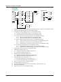
Chapter 1
1.1
Component Names and Functions
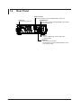
Front Panel
1
Component Names and Functions
2
Display
Displays measured waveforms, measurement conditions, measured values, etc.
Soft key section
Control the functions that are assigned to soft keys,
which appear on the right of the LCD display.
3
FUNCTION section
Set all features including measurement, setup, and display.
4
DATA ENTRY section
Enter measurement condition parameters and labels.
5
POWER
OPTICAL INPUT
Connect the optical input signal here.
6
PRT SCN key
Saves a screen capture
7
LOCAL key
Clears remote mode
REF LASER STATUS LED
Indicates the internal reference light source status
POWER switch
A switch for starting and stopping the AQ6150/AQ6151
8
USB port
Connect a USB storage medium, USB mouse, or USB keyboard.
Index
App
IM AQ6150-01EN
1-1
1.2
Rear Panel
GP-IB connector
Use this connector to control the AQ6150/AQ6151 from a PC.
Power inlet
Connect the power cord.
ETHERNET port
Use this port to connect the AQ6150/AQ6151 to a network.
(10/100/1000BASE-TX)
USB port
Connect a USB storage medium, USB mouse,
or USB keyboard.
VIDEO OUT
Video signal (VGA) terminal
Use this terminal to view the AQ6150/AQ6151 screen
on an external display.
1-2
IM AQ6150-01EN
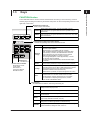
1.3
Keys
1
Component Names and Functions
FUNCTION Section
2
The FUNCTION section consists of three measurement control keys, six function keys, and two
auxiliary keys. Pressing a function key shows the setup menu for the corresponding function on the
right side of the screen.
3
Measurement control keys
Starts or stops measurement
Starts repeat measurements. The key illuminates while the
REPEAT measurement is in progress. Measurement is repeated until you
press STOP.
Starts a single measurement. The key illuminates while the
SINGLE measurement is in progress. Measurement automatically stops after
one measurement.
STOP
4
Stops the measurement.
5
Internal reference light source status display
Indicates the operating status of the internal He-Ne laser
Off
The laser is not being output. Measurement is not possible.
Blinking
orange
Laser output is in preparation. This indicates the status until
the laser output stabilizes.
Measurement is not possible while the message
“REF LASER STARTING” is displayed. If this status lasts
approximately 5 minutes, the AQ6150/AQ6151 assumes
that a malfunction has occurred and turns the LED red.
When the AQ6150/AQ6151 is ready to measure,
the message disappears. It takes approximately 1 minute
for the laser output to stabilize.
To make accurate measurements, wait for the laser output
to stabilize.
Auxiliary key
See section 1.1.
Remote control indicator
Illuminates in remote
control mode.
See section 1.2
in the User’s Manual
IM AQ6150-17EN.
Green
Normal status (stable laser output). Measurement is possible.
Orange
When the light source approaches its service life, the message
“It is about time to plan for REF LASER replacement" appears.
The operating time of the laser output has reached the
replacement reference time (30,000 hours).
Measurement is possible, but replace the light source quickly.
Red
If a malfunction occurs, the message “REF LASER or
interferometer is out of order. Please contact our sales
representatives” appears. Measurement is not possible.
For information on replacing the light source, contact
your nearest YOKOGAWA dealer.
6
7
8
Index
App
Function keys
Set measurement conditions, data saving and loading, etc.
DISPLAY
Displays a setup menu for selecting measurement screens and
setting waveform display scales
SEARCH
Displays a setup menu for searching measured peaks
ANALYSIS Displays a setup menu for taking drift measurements and performing
FP-LD analysis
IM AQ6150-01EN
SETUP
Displays a setup menu for setting measurement conditions
(type of light, detection threshold, unit, etc.)
FILE
Displays a setup menu for saving and loading measured data and
settings from a USB storage device or internal memory
SYSTEM
Displays a setup menu for setting network parameters, showing
system information, setting the clock, and so on
1-3
1.3 Keys
DATA ENTRY Section
You can enter various measurement parameters from the DATA ENTRY section.
You can enter parameters using the arrow keys or numeric keypad.
COARSE key
Turn this key on to select the next higher digit or increases the step by
which the value changes.
Each time you press the key, the setting toggles between on and off.
When set to on, the key illuminates.
Arrow keys
Increase or decrease values, move the cursor (up and down) in file lists,
move the cursor (up, down, left, and right) in the character selection area
of character input screens, enter numeric keypad values (left and right),
and so on.
To increase a value: ▲ or ► key
To decrease a value: ▼ or ◄ key
BACK SPACE key
Press this key to erase the key before the cursor.
The last entered number (at the right end) is erased, and you can enter
the correct number.
If you press BACK SPACE repeatedly and the numeric keypad input area
becomes empty, the numeric keypad input area disappears.
ENTER key
Confirms the value that you have entered with the numeric keypad,
in the parameter input window, or character input screen.
Numeric keypad
You can use the numeric keypad to enter values directly in parameter input windows.
If you press a soft key that has a parameter, the current value appears in a parameter
value display area. If you press a key on the numeric keypad in this condition, the number
that you selected appears in the area.
If the value that you enter with the numeric keypad is outside the allowed range, it is reset
to the closest value within the range.
1-4
IM AQ6150-01EN
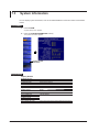
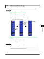
1.4
Screens
1
Component Names and Functions
2
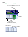
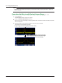
Main Screen
Measurement result display
Displays the peak window, peak list window, and spectrum window.
The display varies depending on the VIEW mode. Details are given later.
3
Measurement summary
Displays the number of detected peaks
(PEAK), center wavelength (CTR WL),
and total power (TOTAL PWR)
Label
You can display text of
your choice using up to
52 characters.
4
Date and time
Measurement parameter value input
5
Numeric keypad screen
If you connect a mouse to the AQ6150/AQ6151,
you can perform the same operations that
you can using the front panel’s numeric keypad.
Setup menu
6
7
Light type setting
(Narrow or Broad)
Peak detection threshold
and excursion values
8
Averaging count
Measurement control keys
Indicates the state of the measurement control keys.
If you connect a mouse to the AQ6150/AQ6151, you
can click these keys to perform the same operations
that you can using the front panel’s measurement
control keys.
RPT: Repeat measurement
SGL: Single measurement
STP: Stop measurement
The medium setting (vacuum or air)
Illuminates when measurement wavelength range
limit is on (see section 3.5)
Illuminates when the power offset is not zero
(see section 2.7 of the Getting Started Guide, IM AQ6150-02EN.)
Illuminates when the auto peak search feature is on
IM AQ6150-01EN
1-5
Index
App
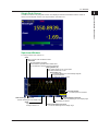
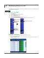
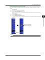
1.4 Screens
Multi Peak Screen for Absolute Values
For the procedure, see section 4.2.
Current peak number/the number of detected peaks
Indicates which peak among the detected peaks is shown in the peak window.
Example: 10th peak among the 32 peaks detected
Wavelength
The wavelength of the current peak
Peak value
Indicates that the current peak is the maximum (power)
Power bar
The ratio of the power value
Power
The power the current peak
Peak window
Peak list window
A list of detected peaks
Power bar
Ratio of the power of each peak relative
to the maximum measurable power
Power
The power of each peak
Wavelength
The wavelength of each peak
Number
Numbers automatically assigned to all detected peaks
Cursor display
Move the cursor to select the peak (current peak) to show in the peak window.
Multi Peak Screen for Relative Values
The peak window is the same as with the multi peak screen for absolute values, shown above. For the
procedure, see section 4.3.
ΔWL
Wavelength relative to the reference (REF) peak
ΔPW
Power relative to the reference (REF) peak
1-6
IM AQ6150-01EN
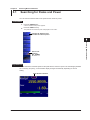
1.4 Screens
1
Single Peak Screen
Component Names and Functions
A screen that shows only the peak window. The displayed contents and features are the same as
those of the multi peak screens. For the procedure, see section 4.1.
2
3
4
5
6
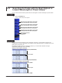
Spectrum Window
For the procedure, see section 4.4.
7
Scale
Displays a power scale of absolute values
Threshold
The peak detection threshold.
If the threshold is specified with a relative value,
it is converted to an absolute value and displayed.
Moving marker (▼)
This marker appears on the current peak.
The marker is filled with a color.
8
Fixed marker ( )
A numbered marker that is automatically assigned
during peak detection
The maximum number is 1024.
Index
App
Overview window
The entire spectrum waveform
Start wavelength of the scale
The start wavelength of the display range
Zoom
Appears when the spectrum
is being zoomed in on
IM AQ6150-01EN
Stop wavelength of the scale
The stop wavelength of the display range
Wavelength per division
Center wavelength of the scale
The center wavelength of the display range
1-7
Chapter 2
2.1
Measurement Setup
Setting the Peak Detection Threshold and
Excursion Values
1
2
Measurement Setup
Set the parameters for detecting wavelengths.
• Peak Threshold
• Peak Excursion
Procedure
3
Peak Thresh Type
Set whether to use an absolute value or relative value to specify the threshold.
4
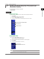
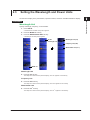
1. Press SETUP.
A measurement condition setup menu appears.
2. Press the PEAK THRESH TYPE soft key.
Each time you press the soft key, the setting toggles between REL and ABS.
5
Threshold definition mode (REL, ABS)
6
Set the threshold.
7
Set peak excursion.
8
Index
Peak Thresh Value
App
Set the threshold as a value.
3. Press the PEAK THRESH VALUE soft key.
A screen for setting the threshold level appears.
4. Enter the threshold using the arrow keys or numeric keypad.
5. Press ENTER.
The specified threshold appears on the soft key.
Enter the value.
You do not have to enter a unit.
Note
The unit changes automatically according to the mode setting.
In REL mode, the unit is dB. In ABS mode, the unit is dBm.
IM AQ6150-01EN
2-1
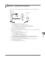
2.1 Setting the Threshold for Peak Detection
Peak Excursion
Set the amount of power change from the peak value (the difference between the peak and valley) as
a value. The peak power is automatically measured.
2. Press the PEAK EXCURSION soft key.
A screen for setting the power difference appears.
3. Enter the value using the arrow keys or numeric keypad.
Enter the value.
You do not have to enter a unit.
4. Press ENTER.
The power difference that you enter appears on the soft key.
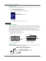
Explanation
Peak Threshold
Set the power threshold for detecting wavelengths. Set the threshold using a relative value from the
power peak (when PEAK THRESH TYPE is REL) or an absolute power value (when PEAK THRESH
TYPE is ABS). If you specify –30 dB using a relative value, the threshold is set to a value that is 30 dB
less than the peak value. Wavelengths that exceed this threshold power are measured.
The range of threshold values that you can specify are shown below. If you specify a value greater
than the upper limit, the threshold is set to the upper limit. If you specify a value less than the lower
limit, the threshold is set to the lower limit.
• ABS (absolute value): –40.0 dBm to 10.0 dBm
• REL (relative value): 0 dB to 40.0 dB
10.0
10.0
–10.0
–10.0
dBm
Peak value
30 dB
dBm
–30.0
Threshold
(THR)
–50.0
Threshold
(THR)
–30.0
–50.0
THR = –30 dBm in ABS mode
THR = 30 dB in REL mode
Peak Excursion
Peaks whose amount of power changes from the peak value (the difference between the peak and
valley) is greater than the specified value are measured.
This peak is detected (because the difference
between the peak and valley is greater than 3 dB).
4 dB
2 dB
This peak is not detected
(because the difference between the peak
and valley is less than 3 dB).
1 dB
Example: When peak excursion is
set to 3 dB
2-2
IM AQ6150-01EN
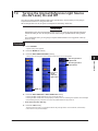
2.1 Setting the Threshold for Peak Detection
1
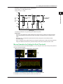
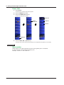
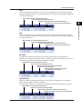
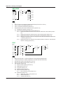
Example of Setting Peak Detection Parameters
Peak Thresh = 10 dB (Relative mode)
Peak Excursion = 15 dB
-5
Power (dBm)
-15
-20
(C)
(A)
Peak Excursion
= 15 dB
Peak Excursion
= 15 dB
3
Peak Threshold
= 10 dB (REL)
(D)
(B)
Measurement Setup
-10
2
Peak Excursion
= 15 dB
-25
4
(E)
-30
5
Wavelength
In the above example, only (A) and (C) are detected as peaks.
Explanation
• (A) and (C) are detected as peaks because their peak powers are within the Peak Threshold
range and the differences between the peak and valley are greater than the Peak Excursion
value.
• (B) and (E) are not detected as peaks because their peak powers are outside the Peak
Threshold range.
• (D) is not detected as a peak because even though its peak power is within the Peak Threshold
range, the difference between the peak and valley is less than the Peak Excursion value.
6
7
8
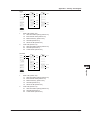
Mouse Operation for Setting the Peak Threshold
If you connect a mouse to the AQ6150/AQ6151, you can drag the cursor from the top of the spectrum
window to set the threshold.
Index
When the cursor changes to a hand cursor, you can drag.
App
Drag
For details on connecting a mouse, see section 2.5 in IM AQ6150-02EN.
For details on how to use the spectrum window, see section 4.3.
IM AQ6150-01EN
2-3
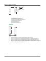
2.2
Setting the Medium (Vacuum or Standard Air)
That Light Travels Through
Set the actual medium in which the light under measurement will be used.
Procedure
Setting the Medium
Set the medium to vacuum or standard air.
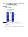
1. Press SETUP.
A measurement condition setup menu appears.
2. Press the MORE 1/2 soft key.
3. Press the MEAS WL soft key.
Each time you press the soft key, the setting toggles between AIR and VACUUM.
Medium type
(AIR, VACUUM)
MORE 1/2
Explanation
The wavelength of light varies depending on the medium that it travels through.
To accurately measure the wavelength, set the actual medium in which the light will be used.
If you specify AIR (standard air), measured results will be converted for the following conditions.
• Air pressure 760 torr
• Temperature 15°C
• Humidity
0%
Even if the actual ambient temperature is 25°C, the AQ6150/AQ6151 converts the measured results
for 15°C.
2-4
IM AQ6150-01EN
2.3
Setting the Wavelength and Power Units
1
Set the unit to display in the peak window, spectrum window, and list on the AQ6150/AQ6151 display.
Measurement Setup
Procedure
2
Wavelength Unit
3
Specify wavelength, frequency, or wavenumber.
1. Press SETUP.
A measurement condition setup menu appears.
4
2. Press the MORE 1/2 soft key.
3. Press the WAVELENGTH UNIT soft key.
A wavelength unit setup menu appears.
Set the
wavelength unit.
5
Wavelength unit (nm)
Frequency unit (THz)
Wavenumber unit (cm–1)
6
7
8
Index
MORE 1/2
Wavelength Unit
App
4. Press the nm soft key.
The setup menu returns to the previous display, and “nm” appears on the soft key.
Frequency Unit
4. Press the THz soft key.
The setup menu returns to the previous display, and “THz” appears on the soft key.
Wavenumber Unit
-1
4. Press the cm soft key.
-1
The setup menu returns to the previous display, and “cm ” appears on the soft key.
IM AQ6150-01EN
2-5
2.3 Setting the Wavelength and Power Units
Power Unit
1. Press SETUP.
A measurement condition setup menu appears.
2. Press the MORE 1/2 soft key.
3. Press the POWER UNIT soft key.
A power unit setup menu appears.
dBm unit
Set the
power unit.
mW unit
µW unit
MORE 1/2
4. Press the dBm, mW, or µW soft key.
The setup menu returns to the previous display, and the specified unit appears on the soft key.
Explanation
Wavenumber
Wavenumber is a unit that expresses how many waves (peaks) are in a centimeter.
It is the reciprocal of the wavelength divided by 100.
Example: 1/1550 nm ÷ 100 ≈ 6452 cm-1
2-6
IM AQ6150-01EN
2.4
Configuring the CW Light (DFB-LD and FP-LD)
Measurement
1
2
Select the light type for measuring an LD light source.
Measurement Setup
Procedure
Light Type
3
1. Press SETUP.
A measurement condition setup menu appears.
2. Press the DEVICE TYPE soft key.
4
A light type setup menu appears.
3. Press the CW(NARROW) soft key.
The setup menu returns to the previous display, and “CW” appears on the soft key.
Light type
(CW, MODULATED)
5
Set the CW light.
6
7
8
Index
Note
• If the output of the light source under measurement is not stable, set averaging as necessary. For details
on averaging, see section 3.3.
• To measure the peak under measurement separately from the side modes that appear near it, set a limit
on the range of measured wavelength. For details, see section 3.5.
IM AQ6150-01EN
2-7
App
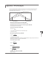
2.4 Configuring the CW Light (DFB-LD and FP-LD) Measurement
FP-LD Analysis
The AQ6150/AQ6151 can automatically perform FP-LD (Fabry-Perot) analysis for each measurement
and display the results.
1. Press the ANALYSIS key.
An analysis setup menu appears.
2. Press the FABRY-PEROT LASER soft key.
A screen for displaying FP-LD analysis results appears.
Set the
FP-LD
analysis.
FP-LD analysis results
Explanation
FP-LD Analysis
In FP-LD analysis, the following items are computed, and their results are displayed.
• Peak Power (maximum peak value): PEAK PWR
• Peak Wavelength (wavelength at maximum peak): PEAK WL
• Total Power (total peak): TOTAL PWR
• Mode Spacing (peak spacing): ΔλMODE
• Center Wavelength (mean wavelength): CTR WL
• Full Width at Half Maximum (FWHM): FWHM
• Sigma (Σ): σ
For detailed equations, see appendix 2.
Wavelength and Power Measurement of a Peak in a CW Light
(Narrow)
The value on the horizontal scale where the peak optical power is maximum is assumed to be the
peak’s wavelength, frequency, or wavenumber.
The value on the vertical scale where the peak optical power is maximum is assumed to be the peak’s
power.
Maximum power
Wavelength, frequency, or wavenumber
2-8
IM AQ6150-01EN
2.5
Configuring the Modulated Light
(10G or 40G modulation, LED) Measurement
1
2
Select the light type for measuring a modulated light or LED.
Measurement Setup
Procedure
Light Type
3
1. Press SETUP.
A measurement condition setup menu appears.
2. Press the DEVICE TYPE soft key.
4
A light type setup menu appears.
3. Press the MODULATED(BROAD) soft key.
The setup menu returns to the previous display, and “MODULATED” appears on the soft key.
5
Light type
(CW, MODULATED)
Set the modulated
light.
6
Set peak excursion.
7
Set averaging.
8
Index
Peak Excursion
The wavelength and power of a modulated light are determined by the power difference from the peak
value. Peak Excursion is also used to detect peaks. For the procedure, see section 2.1.
For details on the measured values of optical wavelength and power, see the explanation.
IM AQ6150-01EN
2-9
App
2.4 Configuring the CW Light (DFB-LD and FP-LD) Measurement
Explanation
Wavelength and Power Measurement of a Peak in a Modulated
Light (Broad)
Computation range
Maximum power
Peak
excursion
value
The area of the hatched section (integral)
is the power P.
P
f1
fcenter
fn
• Wavelength, Frequency, or Wavenumber
The center-of-gravity value of the horizontal bandwidth defined by the value where the peak
optical power is maximum to the value where the power is peak excursion value (dB) less than
the maximum power is assumed to be the peak’s wavelength, frequency, or wavenumber.
The center-of-gravity value (fcenter) is computed with the following equation.
n
fcenter =
∑ (Pi x fi)
i=1
n
∑ Pi
i=1
Pi = Power at each measurement point within the computation range
fi = F
requency at each measurement point within the computation range
• Power
The integral value calculated over the horizontal bandwidth (f1 to fn), which is defined by the
value where the peak optical power is maximum to the value where the power is peak excursion
value (dB) less than the maximum power, is assumed to be the peak’s power.
2-10
IM AQ6150-01EN
2.6
1
During single or repeat measurement, the auto wavelength or power search feature automatically
searches for the peak with the maximum power and displays the peak on the screen. To search the
peak manually, see section 5.1.
2
Procedure
Measurement Setup
Turning Auto Wavelength or Power Searching
On and Off
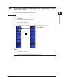
3
Turning Auto Search On or Off
1. Press the SEARCH key.
4
A search condition setup menu appears.
2. Press the MORE 1/2 soft key.
3. Press the AUTO PEAK SEARCH soft key.
Each time you press the soft key, the setting toggles between OFF and ON.
5
Turns auto search
on and off
6
7
8
Index
MORE 1/2
App
Explanation
Auto Search
Auto Search always searches for the peak with the maximum power.
IM AQ6150-01EN
2-11
Chapter 3
3.1
Executing Measurements
Single Measurement
1
2
Under the conditions specified in chapter 2, the AQ6150/AQ6151 measures once and displays the
results on the screen.
CAUTION
3
Executing Measurements
• Do not apply light that is +18 dBm or greater to the optical connector of the AQ6150/
AQ6151. Doing so may damage the optical components in the AQ6150/AQ6151.
• If you want to use a light that is +18 dBm or greater, use an optical attenuator to adjust the
light to less than +18 dBm.
4
Procedure
5
1. Press the SINGLE key.
The SINGLE key illuminates to indicate that a measurement has started. When the measurement is
complete, the SINGLE key turns off.
6
Note
• If the AQ6150/AQ6151 detects an optical input power that exceeds the allowable limit, the message
“Input power too high” appears on the screen, and the measurement stops. For details on messages, see
section 8.1.
• If you change the power offset, redo the measurement.
• If averaging is enabled, the AQ6150/AQ6151 measures for the specified number of times and completes
the single measurement. For details on how to set averaging, see section 3.3.
7
8
Explanation
Measurement Range
In a single measurement, the AQ6150/AQ6151 sweeps the measurement range of 1270 nm to 1650
nm once. You cannot stop the measurement while sweeping is in progress. If you press STOP, the
measurement will stop after the current sweeping is finished.
To change the measurement range, see section 3.5.
Peak Detection
When peaks that exceed the threshold power are present in the measurement range, the AQ6150/
AQ6151 measures their wavelengths and power values and displays the results on the screen. The
AQ6150/AQ6151 can display up to 1024 peaks.
If the AQ6150/AQ6151 detects no peaks, the “No Signal” message appears on the screen.
In such cases, check the threshold and peak excursion values (see section 2.1).
Spurious Noise
Spurious noise may be measured depending on the measurement conditions. For details, see
appendix 3.
IM AQ6150-01EN
3-1
Index
App
3.2
Repeat Measurement
Under the conditions specified in chapter 2, the AQ6150/AQ6151 makes repeated measurements and
updates the measurement results on the screen.
CAUTION
• Do not apply light that is +18 dBm or greater to the optical connector of the AQ6150/
AQ6151. Doing so may damage the optical components in the AQ6150/AQ6151.
• If you want to use a light that is +18 dBm or greater, use an optical attenuator to adjust the
light to less than +18 dBm.
Procedure
1. Press the REPEAT key.
The REPEAT key illuminates to indicate that a measurement has started. Measurement is repeated until
you press STOP.
Note
• If the AQ6150/AQ6151 detects an optical input power that exceeds the allowable limit, the message
“Input power too high” appears on the screen, and the measurement stops. For details on messages, see
section 8.1.
• If you change the power offset after a measurement, redo the measurement.
• If averaging is enabled, the AQ6150/AQ6151 measures for the specified number of times and updates the
measured results. For details on how to set averaging, see section 3.3.
Explanation
Measurement Range
In a repeat measurement, the AQ6150/AQ6151 sweeps the measurement range of 1270 nm to
1650 nm repeatedly. You cannot stop the measurement while sweeping is in progress. If you press
STOP, the measurement will stop after the current sweeping is finished.
To change the measurement range, see section 3.5.
Peak Detection
When peaks that exceed the threshold power are present in the measurement range, the AQ6150/
AQ6151 measures their wavelengths and power values and updates the results on the screen. The
AQ6150/AQ6151 can display up to 1024 peaks.
If the AQ6150/AQ6151 detects no peaks, the “No Signal” message appears on the screen.
In such cases, check the threshold and peak excursion values (see section 2.1).
Spurious Noise
Spurious noise may be measured depending on the measurement conditions. For details, see
appendix 3.
3-2
IM AQ6150-01EN
3.3
Averaged Measurement
1
Under the conditions specified in section 3.1 or 3.2, the AQ6150/AQ6151 averages the measured data
of multiple sweeps and displays the measured results.
Procedure
Setting Averaging
1. Press SETUP.
3
Executing Measurements
The AQ6150/AQ6151 measures for the specified number of times, averages the measured values, and
displays the results. The following procedure is for setting the measurement count (Average Times).
2
4
A measurement condition setup menu appears.
2. Press the AVERAGE TIMES soft key.
A screen for setting the measurement count appears.
3. Enter the measurement count using the arrow keys or numeric keypad.
5
Enter the value.
6
7
4. Press ENTER.
The specified measurement count appears on the soft key.
8
Note
• Simply changing the average setting will not change the results that have already been measured
according to the procedure in section 3.1 or 3.2.
Redo the measurements explained in section 3.1 or 3.2.
• If you press STOP while a measurement explained in section 3.1 or 3.2 is in progress, the measurement
will stop even if the specified measurement count has not been reached.
• If the AQ6150/AQ6151 detects an optical input power that exceeds the allowable limit while a
measurement explained in section 3.1 or 3.2 is in progress, the measurement will stop even if the
specified measurement count has not been reached.
• If you switch between single measurement and repeat measurement or change measurement conditions
during averaged measurement, the averaged data up to that point is discarded, and measurement is
performed again for the specified number of times.
Explanation
Averaging
If the measurement count (Average Times) is set to 2 or higher, the AQ6150/AQ6151 computes the
average wavelength and power of the measured results.
In a single measurement, the AQ6150/AQ6151 measures for the specified number of times, computes
and displays the average values, and then stops the measurement.
In a repeat measurement, the AQ6150/AQ6151 computes the moving averages with the most recent
measurement and the specified number of measurements and updates the values on the screen.
Averaging can be performed over 2 to 100 times. If the measurement count is set to 1, averaging is
not performed.
Averaging for single and repeat measurements are based on the peaks that are detected in the first
sweep. If the peaks that are detected in subsequent sweeps differ from those of the first sweep,
averaging is processed in the following manner.
• Additional peaks (peaks that are not detected in the first sweep) are not averaged.
IM AQ6150-01EN
3-3
Index
App
3.4 Drift Measurement
• Dropped peaks (peaks that are detected in the first sweep but are not in subsequent sweeps) are
not averaged. For such peaks, “DROP” appears on the screen.
For details on single measurement, see section 3.1.
For details on repeat measurement, see section 3.2.
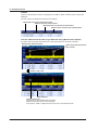
Display during Averaged Measurement
Averaged peaks
The most recent measured
data is displayed in gray.
Shows averaged peak measurements
Display When a Peak Is No Longer Detected during Averaged Measurement
DROP indication
The No. 1 peak is lost.
If a peak is lost from the most recent measured data (gray), averaged measurement on the peak is aborted.
The peak (averaged measurement result) before it was lost remains on the screen, but averaging is not
performed after it is lost. If this happens, “DROP” is displayed for the power value in the measured results.
3-4
IM AQ6150-01EN
3.4
Drift Measurement
1
2
Under the conditions specified in section 3.1 or 3.2, the AQ6150/AQ6151 measures the amount of
change in the peaks’ wavelength and power values.
Procedure
3
Turning Drift Measurement On or Off
Executing Measurements
1. Press the ANALYSIS key.
An analysis setup menu appears.
4
2. Press the DRIFT MEASURMENT soft key.
A drift measurement parameter setup menu and a result screen appear.
5
Configure
the drift
measurement.
6
7
8
Reference (No. 1 in this example)
Peak wavelength and power
Index
Drift measurement results
The reference area shows the values for the peak that the cursor is on in the drift measurement
result display (list display).
You can select what to display for the drift measurement results by following the procedure on
the next page. The example above shows the screen when wavelength (difference from the
reference, maximum, and minimum) is specified. The display contents can be changed even
after a measurement is finished.
Note
Averaged measurement cannot be performed during drift measurement. If you enable drift measurement, the
measurement count for averaging (AVERAGE TIMES) will be set to 1.
IM AQ6150-01EN
3-5
App
3.4 Drift Measurement
Selecting the Measurement Item
Select the item that you want to show for the drift measurement results.
3. Press the PARAMETER SETTING soft key.
A DISPLAY MODE setup menu appears.
4. Press the DISPLAY MODE soft key.
A display item setup menu appears.
Difference from the reference
(wavelength and power)
Initializes
the reference
Maximum value since the start of
measurement (wavelength and power)
Select the
measurement
item.
Minimum value since the start of
measurement (wavelength and power)
Difference between the maximum and
minimum since the start of measurement
(wavelength and power)
Wavelength
(Difference, maximum, and minimum)
Initializes
the settings
Power
(Difference, maximum, and minimum)
Initializing the Reference Value
You can initialize (clear) the peak reference values (wavelength and power values).
3. Press the REF SET soft key.
All peak reference values are cleared.
Explanation
Selecting the Measurement Item
DELTA
The differences between the current measurement peak and the reference peak are displayed.
The wavelength and power values are displayed. The units of wavelength, frequency, or
wavenumber and power are displayed according to the settings.
Wavelength of the current measurement result
Power of the current measurement result
Difference from the reference wavelength
3-6
Difference from the reference power
IM AQ6150-01EN
3.4 Drift Measurement
MAX
The maximum values since the start of measurement are displayed. The wavelength and power
values are displayed. The units of wavelength, frequency, or wavenumber and power are displayed
according to the settings.
Wavelength of the current measurement result
1
2
Power of the current measurement result
Maximum wavelength since the start of measurement
3
Maximum power since the start of measurement
Executing Measurements
4
MIN
The minimum values since the start of measurement are displayed. The wavelength and power
values are displayed. The units of wavelength, frequency, or wavenumber and power are displayed
according to the settings.
Wavelength of the current measurement result
5
6
Power of the current measurement result
Minimum wavelength since the start of measurement
Minimum power since the start of measurement
7
8
MAX-MIN
The differences between the maximum and minimum since the start of measurement are
displayed. The wavelength and power values are displayed. The units of wavelength, frequency, or
wavenumber and power are displayed according to the settings.
Wavelength of the current measurement result
Index
Power of the current measurement result
Maximum amount of change in the wavelength
since the start of measurement
App
Maximum amount of change in the power
since the start of measurement
WAVELENGTH
Only the measured wavelengths, frequencies, or wavenumbers are displayed. The measured
values of DELTA, MAX, and MIN are displayed.
The wavelength, frequency, or wavenumber is displayed automatically according to the settings.
Wavelength of the current measurement result
Difference from the reference wavelength
Maximum wavelength since the start of measurement
IM AQ6150-01EN
Minimum wavelength since the start of measurement
3-7
3.4 Drift Measurement
POWER
Only the measured power values are displayed. The DELTA, MAX, and MIN values of power are
displayed.
The unit of power is displayed according to the settings.
Wavelength of the current measurement result
Difference from the reference power
Maximum power since the start of measurement
Minimum power since the start of measurement
Indication When Peaks Are No Longer Detected during Measurement (DROP)
If a peak is lost during drift measurement, the drift measurement of that peak is aborted.
Display during drift measurement
Peaks during drift measurement
(No.1 to No.4)
The No. 1 peak is lost.
DROP indication
The No. 1 peak is lost.
If the peak is lost, its drift measurement is aborted.
Measured values after the loss are not displayed.
If this happens, “DROP” is displayed for the power value in the measured results.
3-8
IM AQ6150-01EN
3.5
Measuring Only a Specific Wavelength
1
2
When making measurements under the conditions specified in section 3.1 or 3.2, you can limit the
measurement range in which to detect peaks.
Procedure
3
Turning On or Off the Measurement Range Limit
Executing Measurements
1. Press SETUP.
A measurement condition setup menu appears.
4
2. Press the WAVELENGTH LIMIT soft key.
A measurement range limit setup menu appears.
3. Press the LIMITING MODE soft key.
Each time you press the soft key, the setting toggles between ON and OFF. When set to ON, the
measurement range can be limited.
5
Turns on or off the
measurement range limit
6
Set the start wavelength of
the measurement range limit.
Set the stop wavelength of
the measurement range limit.
7
Measurement
range limit
8
Index
App
Setting the Limit Start Wavelength
4. Press the LIMIT START WL soft key.
A screen for setting the start wavelength appears.
Enter the value.
You do not have to enter a unit.
5. Enter the start wavelength using the arrow keys or numeric keypad.
6. Press ENTER.
The specified start wavelength appears on the soft key.
IM AQ6150-01EN
3-9
3.5 Measuring Only a Specific Wavelength
Setting the Limit Stop Wavelength
4. Press the LIMIT STOP WL soft key.
A screen for setting the stop wavelength appears.
Enter the value.
You do not have to enter a unit.
5. Enter the stop wavelength using the arrow keys or numeric keypad.
6. Press ENTER.
The specified stop wavelength appears on the soft key.
Note
The soft key name and value are displayed according to the wavelength (vacuum), frequency, or
wavenumber settings.
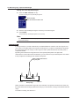
Explanation
In a single sweep of a normal measurement, the AQ6150/AQ6151 measures over the range of 1270
nm to 1650 nm to detect peaks and compute the total power. If you place a measurement range limit,
the sweep range does not change, but the range over which peaks are detected and total power is
computed is limited.
By limiting the measurement range when there are superimposed peaks in the light under
measurement or when side modes are detected, you can measure only the desired peak. This makes
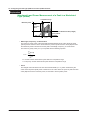
it easy to adjust the wavelength and check the total power.
Want to adjust and measure
only this peak
Measurement range
1270 nm
Sweep range
1650 nm
Peaks outside the measurement range will not be detected. The spectrum waveform will consist only
the peaks within the limit range (measurement range). In this situation, scaling is also limited within the
range.
For details on scaling, see section 4.4.
3-10
IM AQ6150-01EN
Chapter 4
4.1
Displaying Measured Results
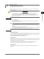
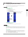
Displaying Only One Pair of Values
1
2
You can select to display only one pair (wavelength and power) of peak measurement results. For
details on the screen, see “Single Peak Screen” in section 1.4.
Procedure
3
Setting the View Mode
1. Press DISPLAY.
2. Press the VIEW MODE soft key.
4
3. Press the SINGLE WAVELENGTH soft key.
Displaying Measured Results
A screen display condition setup menu appears.
A view mode setup menu appears.
The setup menu returns to the previous display, and “SINGLE-WL” appears on the soft key.
Set the view mode.
5
Sets the single peak display
6
7
8
Sets the sort
condition
(WL, POWER)
Index
Setting the Sort Condition
App
2. Press the LIST BY soft key.
Each time you press the soft key, the setting toggles between WL and POWER.
Explanation
View Mode
When the AQ6150/AQ6151 detects multiple peaks during measurement, it retains data for up to 1024
peaks. The view mode specifies how to display these peaks. This section explains how to display one
pair of measurement results for the current peak. To display multiple measurement results, see section
4.2.
Sort Condition
You can sort the measured results in the AQ6150/AQ6151 in descending order by wavelength or
power. Peak and peak power searching is performed in accordance with this sort order. For details on
how to search for peaks or peak power, see chapter 5.
WL: Peaks are displayed in ascending order by wavelength (frequency or wavenumber)
POWER: Peaks are displayed in descending order by power.
IM AQ6150-01EN
4-1
4.2
Displaying Values in a List
You can display peak measurement results in a list. For details on the screen, see “Multi Peak Screen
for Absolute Values” in section 1.4.
Procedure
Setting the View Mode
1. Press DISPLAY.
A screen display condition setup menu appears.
2. Press the VIEW MODE soft key.
A view mode setup menu appears.
3. Press the MULTI WAVELENGTH soft key.
The setup menu returns to the previous display, and “MULTI-WL” appears on the soft key.
Set the view mode.
Turns on or off
the fullscreen
list display
Sets the multi peak display
Sets the sort
condition
(WL, POWER)
► section 4.1
Fullscreen List Display
You can select to display only the list by clearing the peak window display.
4. Press the LIST ONLY soft key.
Each time you press the soft key, the setting toggles between ON and OFF. When set to ON, the list is
displayed in fullscreen.
4-2
IM AQ6150-01EN
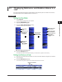
4.3
Displaying Reference and Relative Values in a
List
1
You can list the measured results of values relative to the reference peak. For details on the screen,
see “Multi Peak Screen for Relative Values” in section 1.4.
2
Procedure
3
Setting the View Mode
1. Press DISPLAY.
A screen display condition setup menu appears.
4
2. Press the VIEW MODE soft key.
A view mode setup menu appears.
A reference peak setup menu appears.
Moves the cursor
on the list up
Set the view
mode.
Turns on or off
the fullscreen
list display
► section 4.2
Sets the multi
peak display
(relative value)
Moves the cursor
on the list down
Sets the reference
to the peak
selected by the
cursor
Displaying Measured Results
3. Press the DELTA WAVELENGTH soft key.
5
6
7
8
Sets the sort
condition
(WL, POWER)
► section 4.1
Index
App
• When Not Setting the Reference
4. Press the RETURN soft key.
The setup menu returns to the previous display, and “DELTA-WL” appears on the soft key.
Setting the Reference Peak
4. Move the cursor in the list to the peak you want to set as the reference using the up and down
arrow soft keys.
5. Press the REF SELECT soft key.
The character string “REF” appears in the relative value columns in the list.
Reference indication
IM AQ6150-01EN
4-3
4.3 Displaying Reference and Absolute Values in a List
Explanation
Relative Value Computation
Relative values ΔWL and ΔPW are computed as follows:
• ΔWL
(wavelength of the current peak) – (wavelength of the reference peak)
• ΔPW
(power of the current peak) – (power of the reference peak)
4-4
IM AQ6150-01EN
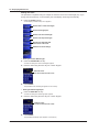
4.4
Displaying Waveforms
1
The AQ6150/AQ6151 displays peak measurement results as spectrum waveforms. For details on the
screen, see “Spectrum Window” in section 1.4.
Procedure
2
3
Displaying the Spectrum Window
1. Press DISPLAY.
A screen display condition setup menu appears.
2. Press the SPECTRUM DISPLAY soft key.
4
Displaying Measured Results
Each time you press the soft key, the setting toggles between ON and OFF. When set to ON, the spectrum
window is displayed.
5
6
Turns on or off the spectrum window
Executes auto scaling
7
Set the scale.
8
Index
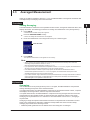
Adjusting (Scaling) the Waveform Display
Executing Auto Scaling
App
3. Press the AUTO SCALE soft key.
The spectrum waveform display is automatically optimized. When you execute auto scaling, a scale display
condition setup menu will appear. For details, see “Setting the Scale.”
Waveform display optimization
with auto scaling
IM AQ6150-01EN
Detected peaks
4-5
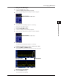
4.4 Displaying Waveforms
Setting the Scale
The procedure is explained using an example in which the unit is set to wavelength (nm). If you
change the unit (frequency or wavenumber), the scale display will change automatically.
3. Press the SCALE soft key.
A scale display condition setup menu appears.
Set the scale’s center wavelength.
Set the wavelength span.
Set the scale start wavelength.
Set the scale stop wavelength.
Displays the maximum peak
in the center of the scale
Initializes the scale settings
• Setting the Center Wavelength
4. Press the CENTER WL soft key.
A screen for setting the center wavelength appears.
5. Enter the value using the arrow keys or numeric keypad.
Enter the value.
You do not have to enter a unit.
6. Press ENTER.
The specified center wavelength appears on the soft key.
• Setting the Wavelength Span
4. Press the SPAN WL soft key.
A screen for setting the wavelength span appears.
5. Enter the value using the arrow keys or numeric keypad.
Enter the value.
You do not have to enter a unit.
6. Press ENTER.
The specified wavelength span appears on the soft key.
4-6
IM AQ6150-01EN
4.4 Displaying Waveforms
1
• Setting the Start Wavelength
4. Press the START WL soft key.
A screen for setting the start wavelength appears.
5. Enter the value using the arrow keys or numeric keypad.
2
Enter the value.
You do not have to enter a unit.
3
4
Displaying Measured Results
6. Press ENTER.
The specified start wavelength appears on the soft key.
5
• Setting the Stop Wavelength
4. Press the STOP WL soft key.
A screen for setting the stop wavelength appears.
6
5. Enter the value using the arrow keys or numeric keypad.
Enter the value.
You do not have to enter a unit.
7
8
6. Press ENTER.
The specified stop wavelength appears on the soft key.
Index
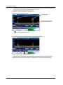
• Displaying the Maximum Peak in the Center of the Scale
4. Press the PEAK -> CENTER soft key.
The peak with the maximum power moves to the center of the scale.
App
Moves the peak to
the center of the scale
Detected peak
• Initializing the Scale Settings
4. Press the INITIAL soft key.
The scale settings are initialized.
IM AQ6150-01EN
4-7
4.4 Displaying Waveforms
Note
Scale settings are automatically changed if you execute auto scaling or display the maximum peak in the
center of the scale.
Expanding the Wavelength Display Using a Mouse
If you connect a USB mouse, you can specify the range to expand by dragging the cursor.
1. Press DISPLAY.
A screen display condition setup menu appears.
2. Press the SPECTRUM DISPLAY soft key.
Each time you press the soft key, the setting toggles between ON and OFF. When set to ON, the spectrum
window is displayed.
3. Drag the range on the spectrum waveform that you want to expand.
The waveform will be displayed expanded.
Drag the range you want to expand (broken-line frame).
4-8
The waveform is expanded so that the left edge
of the broken-line frame is the start wavelength
and the right edge is the stop wavelength.
IM AQ6150-01EN
4.4 Displaying Waveforms
1
Displaying the Overview Window
Even if you change the scale settings by expanding the waveform display, executing auto scaling, and
so on, you can display the waveform over the entire sweep range (1270 nm to 1650 nm) in a small
window.
1. Press DISPLAY.
2
A screen display condition setup menu appears.
2. Press the SPECTRUM DISPLAY soft key.
Each time you press the soft key, the setting toggles between ON and OFF. When set to ON, the spectrum
window is displayed.
3
3. Press the MORE 1/2 soft key.
4. Press the OVER VIEW DISPLAY soft key.
4
Displaying Measured Results
Each time you press the soft key, the setting changes between OFF, L (displayed on the left), and R (displayed
on the right).
5
6
Set the overview window
display mode (OFF, L, R)
7
8
MORE 1/2
Index
Note
For an example of the overview window, see “Spectrum Window” in section 1.4.
App
IM AQ6150-01EN
4-9
4.5
Creating Labels
Procedure
Creating a Label
It is convenient to write information, such as what has been measured and measurement conditions,
on a label when you save measured results.
1. Press DISPLAY.
A screen display condition setup menu appears.
2. Press the MORE 1/2 soft key.
3. Press the LABEL soft key.
A setup menu and a character input screen for entering characters appear.
Create a
label.
Clears the
display
MORE 1/2
Character input screen
Note
• For instructions on how to enter text, see section 3.3 in the Getting Started Guide, IM AQ6150-02EN.
• For the label display position, see “Main Screen” in section 1.4.
4-10
IM AQ6150-01EN
Chapter 5
5.1
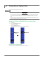
Searching Measured Results
Searching for Peaks and Power
1
You can search measured data for the peak with the maximum power.
2
Procedure
1. Press the SEARCH key.
3
A search condition setup menu appears.
2. Press the PEAK soft key.
The peak with the maximum power is displayed on the screen.
4
Executes the detection of the
peak with the maximum power
5
Searching Measured Results
6
Sets the sort
condition
(WL, POWER)
► section 4.1
7
8
Explanation
You can search the measured peaks for the peak with the maximum power. The wavelength (standard
air or vacuum), frequency, or wavenumber display changes automatically depending on the unit
setting.
App
Peak detection indication
IM AQ6150-01EN
Index
5-1
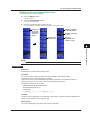
5.2
Searching for Peaks with the Next Highest or
Lowest Wavelength or Power Values
You can search measure data for peaks with the next highest or lowest wavelength or power values.
Procedure
1. Press the SEARCH key.
A search condition setup menu appears.
Searches for the peak with the next lowest
power value after that of the current peak
Searches for the peak with the next highest
power value after that of the current peak
Searches for the peak with the next shortest
wavelength after that of the current peak
Searches for the peak with the next longest
wavelength after that of the current peak
Sets the sort condition
(WL, POWER)
► section 4.1
Explanation
The next and previous searches for the wavelength, frequency, or wavenumber and power are
convenient if you set the appropriate sort condition on the multi peak screen. For details on the multi
peak screen, see section 4.2.
The PREV and NEXT soft keys’ wavelength, frequency, or wavenumber indication changes
automatically depending on the unit setting.
When the Sort Condition Is Set to WL
PREV WL(FREQ/WNUM)
Current peak
NEXT WL(FREQ/WNUM)
When the Sort Condition Is Set to POWER
PREV POWER
Current peak
NEXT POWER
5-2
IM AQ6150-01EN
Chapter 6
6.1
Saving and Loading Data
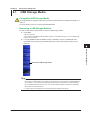
USB Storage Media
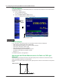
1
Compatible USB Storage Media
The AQ6150/AQ6151 supports USB memory media and USB hard drives compliant with USB 1.0 or
USB 2.0.
For more details, contact your nearest YOKOGAWA dealer.
2
3
Removing a USB Storage Medium
Be sure to follow the procedure below to remove a USB storage medium.
1. Press FILE.
4
2. If not (the REMOVE USB STORAGE soft key is available), press it. The REMOVE USB
5
A file menu appears.
Check whether the REMOVE USB STORAGE soft key is unavailable (dimmed). If it is, the USB storage
medium can be removed.
STORAGE soft key becomes unavailable (dimmed), and the USB storage medium can be
removed.
6
Saving and Loading Data
7
8
Removes the USB storage medium
Index
App
Note
• If there are multiple connected USB storage devices, the AQ6150/AQ6151 detects only the one connected
first. If there is a USB storage device already connected and you connect another, the AQ6150/AQ6151
will not detect it. If you remove the USB storage device that was connected first, the AQ6150/AQ6151
will not automatically detect the other one. If you want the AQ6150/AQ6151 to detect the other device,
disconnect it once and reconnect it.
• For other notes, see the instruction manual supplied with the USB memory device.
IM AQ6150-01EN
6-1
6.2
Saving and Loading Measured Results
You can save measured peak data to a USB storage medium and load data from it.
Procedure
CAUTION
Do not remove the USB storage medium or turn off the power when the USB storage media
access indicator is blinking. Doing so may damage the USB storage medium or corrupt its
data.
Before you remove a USB storage medium, be sure to follow the procedure in section 6.1 to
make the USB storage medium ready to be removed.
Setting the File Type to DATA (Measured Data)
1. Press FILE.
2. Press the ITEM SELECT soft key.
The setup menu changes.
3. Press the DATA soft key.
DATA is selected, and the menu returns to the previous level.
Save or load
measured data.
Set what to
save or load.
6-2
IM AQ6150-01EN
6.2 Saving and Loading Measured Results
1
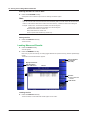
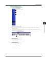
Saving Measured Results
4. Press the WRITE soft key.
A file list appears.
5. Press the MEMORY soft key.
Each time you press the soft key, the setting toggles between INT (internal memory) and EXT (USB storage
media).
The file list of the selected medium appears. The internal memory is the E drive; the USB storage medium
is the F drive.
Sets the
storage medium
(INT, EXT)
Displays the file list
and setup menu of
the save destination
File list
2
3
4
Enter the
file name.
Make a directory.
► section 6.5
5
Sort files.
Saves the data
6
Saving and Loading Data
7
8
Character input screen
Index
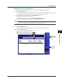
Sorting the File List
If necessary, change the sort order of the file list.
6. Press the FILE SORT soft key.
App
A sort condition setup menu appears.
7. Press the appropriate sort condition soft key. The files are sorted accordingly.
Sorts by file name
Sorts by date and time
Sorts by label
For the label display, see “Main Screen” in section 1.4.
For entering labels, see section 4.5.
IM AQ6150-01EN
6-3
6.2 Saving and Loading Measured Results
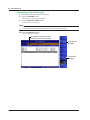
Entering the Name of a File to Save
6. Press the FILE NAME soft key.
A setup menu and a character input screen for entering characters appear.
Note
•
•
For instructions on how to enter text, see section 3.3 in the Getting Started Guide, IM AQ6150-02EN.
If you do not enter a file name, the file name will automatically take on a serial number as describe below.
If there is a file with the same serial number in the same directory, a different number will be assigned.
Example: If 0000, 0001, and 0002 are available, 0003 will be assigned.
If 0000, 0002, and 0003 are available, 0001 will be assigned.
Measured data: D0000.csv, D0001.csv. . .
Setup data: S0000.ws1, S0001.ws1. . .
Screen capture data: G0000.bmp, G0001.bmp. . .
Saving the File
7. Press the EXECUTE soft key.
The file is saved.
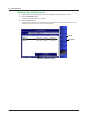
Loading Measured Results
4. Press the READ soft key.
A file list appears.
5. Press the MEMORY soft key.
Each time you press the soft key, the setting toggles between INT (internal memory) and EXT (USB storage
media).
The file list of the selected medium appears.
Displays the file list
and setup menu
of the load source
Sets the medium
to load from
(INT, EXT)
File list
Sort files.
► Saving Measured
Results
Loads the file
Loading the File
6. Press the EXECUTE soft key.
The file is loaded, and the measured results appear on the screen.
6-4
IM AQ6150-01EN
6.2 Saving and Loading Measured Results
1
Explanation
Extension
The extension for measured data is .csv.
2
File Name
You can save files by having their names assigned automatically or with specific names.
Automatic file names range from D0000 to D9999.
To specify the name, use characters that are allowed by MS-DOS. The maximum number of
characters that you can use for file names is 52 (excluding the extension).
The following characters can be used.
ABCDEFGHIJKLMNOPQRSTUVWXYZ
abcdefghijklmnopqrstuvwxyz
0123456789
!! “ # $ % & ‘ ( ) * + , – . / : ; < = > ? @ [ \ ] ^ _ ~ { | }
3
4
5
File Size
The file size varies depending on the data that you are saving. Check that there is sufficient space
on the storage medium before saving the data.
Saving and Loading Data
Sorting Files
You can sort the file list by file name, date and time, and label.
7
Data Format
AQ6150 DATA
R00.25.00
S/N
0123456789
// AQ6150 OPTICAL WAVELENGTH METER //
2012/10/17
14:40:19
DATA TYPE
MULTI WAVELENGTH
DEVICE TYPE
BROADBAND
PEAK TH ABS
-20.0dBm
PEAK EXCURSION 15dB
AVG
1
10
MEDIUM AIR
X UNIT WL
Y UNIT dBm
POWER OFFSET 0.0dB
FP-LD ANALYSIS
PEAK WL[nm]
1549.5698
MEAN WL[nm]
1551.1188
MODE SPACING [nm]
0.1
FWHM [nm]
2.1727
PEAK PWR[dBm] 1.44
TOTAL PWR[dBm] 16.44
SIGMA [nm]
0.9226
Header (measured data) and firmware version
Serial number
Label
Date and time
8
Index
Measurement setup details
App
FP-LD analysis results
(displayed only when executed)
PEAKS 32
AVERAGE WL[nm] 1551.1188
TOTAL PWR[dBm] 16.44
NO.
1
2
3
4
5
IM AQ6150-01EN
WL[nm] PWR[dBm]
1549.5698
1.44
1550.4698
1.44
1551.4694
1.43
1550.5696
1.43
1552.3691
1.43
6
Peak measurement results
6-5
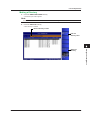
6.3
Saving and Loading Setup Data
You can save the AQ6150/AQ6151 measurement conditions and soft key states to a file in binary
format.
Procedure
CAUTION
Do not remove the USB storage medium or turn off the power when the USB storage media
access indicator is blinking. Doing so may damage the USB storage medium or corrupt its
data.
Before you remove a USB storage medium, be sure to follow the procedure in section 6.1 to
make the USB storage medium ready to be removed.
Setting the File Type to SETTING (Setup Data)
1. Press FILE.
2. Press the ITEM SELECT soft key.
The setup menu changes.
3. Press the SETTING soft key.
SETTING is selected, and the menu returns to the previous level.
Save or load setup data.
Set what to
save or load.
Saving Setup Data
For the procedure, see “Saving Measured Results” in section 6.2.
Loading Setup Data
For the procedure, see “Loading Measured Results” in section 6.2.
6-6
IM AQ6150-01EN
6.3 Saving and Loading Setup Data
1
Explanation
Extension
The extension for setup data is .ws1.
2
File Name
You can save files by having their names assigned automatically or with specific names.
Automatic file names range from S0000 to S9999.
To specify the name, use characters that are allowed by MS-DOS. The maximum number of
characters that you can use for file names is 52 (excluding the extension).
The following characters can be used.
ABCDEFGHIJKLMNOPQRSTUVWXYZ
abcdefghijklmnopqrstuvwxyz
0123456789
!! “ # $ % & ‘ ( ) * + , – . / : ; < = > ? @ [ \ ] ^ _ ~ { | }
3
4
5
File Size
The file size varies depending on the data that you are saving. Check that there is sufficient space
on the storage medium before saving the data.
Saving and Loading Data
Sorting Files
6
You can sort the file list by file name, date and time, and label.
7
8
Index
App
IM AQ6150-01EN
6-7
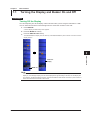
6.4
Saving Screen Capture Data
You can capture the screen and save it as a file.
Procedure
CAUTION
Do not remove the USB storage medium or turn off the power when the USB storage media
access indicator is blinking. Doing so may damage the USB storage medium or corrupt its
data.
Before you remove a USB storage medium, be sure to follow the procedure in section 6.1 to
make the USB storage medium ready to be removed.
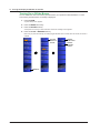
Setting the File Type to GRAPHICS (Screen Capture Data)
1. Press FILE.
2. Press the ITEM SELECT soft key.
The setup menu changes.
3. Press the GRAPHICS soft key.
GRAPHICS is selected, and the menu returns to the previous level.
Set the item
that you want
to save.
Select screen
capture data.
Saving Screen Capture Data
For the procedure, see “Saving Measured Results” in section 6.2.
6-8
IM AQ6150-01EN
6.4 Saving Screen Capture Data
1
Setting the Screen Capture Data Color
Set the color for saving screen captures.
4. Press the WRITE soft key.
2
A file list appears.
5. Press the COLOR MODE soft key.
A color setup menu appears.
6. Press the appropriate color condition soft key.
3
The color condition is selected, and the menu returns to the previous level.
Displays everything
in black and white
Displays the
file list and
setup menu
of the load
source
4
Displays everything
in color
Set the screen
capture color.
Displays
waveforms and
markers in color
5
6
Saving and Loading Data
7
8
Note
For details on the color setting of the AQ6150/AQ6151 display, see section 7.2.
Explanation
Index
Extension
The extension for screen capture data is .bmp.
App
File Name
You can save files by assigning their names automatically or with specific names.
Automatic file names range from G0000 to G9999.
To specify the name, use characters that are allowed by MS-DOS. The maximum number of
characters that you can use for file names is 48 (excluding the extension).
The following characters can be used.
ABCDEFGHIJKLMNOPQRSTUVWXYZ
abcdefghijklmnopqrstuvwxyz
0123456789
!! “ # $ % & ‘ ( ) * + , – . / : ; < = > ? @ [ \ ] ^ _ ~ { | }
File Size
The file size varies depending on the data that you are saving. Check that there is sufficient space
on the storage medium before saving the data.
Sorting Files
You can sort the file list by file name, date and time, and label.
IM AQ6150-01EN
6-9
6.5
File Operation
You can perform file operations such as renaming and copying files.
Procedure
CAUTION
Do not remove the USB storage medium or turn off the power when the USB storage media
access indicator is blinking. Doing so may damage the USB storage medium or corrupt its
data.
Before you remove a USB storage medium, be sure to follow the procedure in section 6.1 to
make the USB storage medium ready to be removed.
Displaying the File Operation Screen
1. Press FILE.
2. Press the FILE OPERATION soft key.
A file operation setup menu and file list appear.
The selected file name and directory
or the specified file name
Displays file
operations
Directory
Sets the medium
► section 6.2
Delete files.
Copy files.
Rename a file.
Make a directory.
Select files.
Moves to the parent directory
Selecting a File or Directory
4. Select files or directories using the arrow keys.
6-10
To move to a child directory, select the directory, and press ENTER.
To move to the parent directory, select “..” and press ENTER.
IM AQ6150-01EN
6.5 File Operations
1
Selecting Multiple Files
4. Press the FILE SELECT soft key.
A file selection menu appears.
2
Select one file at a time.
Selects all files
3
Clears all selections
4
5
6
Saving and Loading Data
• Selecting Files One at a Time
7
5. Move the cursor to the file that you want to select using the arrow keys. Then, press the
SELECT soft key.
The background of the file name where the cursor is at turns gray to show that it is selected. To select
additional files, repeat this procedure.
8
Files that are selected
Index
Cursor
App
• Selecting All Files
5. Press the ALL SELECT soft key.
All files are selected.
• Unselecting All Files
6. Press the ALL CLEAR soft key.
The file selection is cleared.
IM AQ6150-01EN
6-11
6.5 File Operations
Deleting Files and Directories
6. Select the files and directories that you want to delete according to steps 4 and 5.
7. Press the DELETE soft key.
A deletion confirmation setup menu appears.
8. Press the YES soft key.
The selected files and directories are deleted. If you press the NO soft key, the files and folders are not
deleted, and the setup menu returns to the previous display.
Delete
Not delete
Deletion confirmation message
6-12
IM AQ6150-01EN
6.5 File Operations
1
Copying Files and Directories
6. Select the files and directories that you want to copy according to steps 4 and 5.
7. Press the COPY soft key.
A copy operation setup menu and file list appear. If the copy destination medium is different from the copy
source medium, press the MEMORY soft key to select the medium (see section 6.2).
2
8. To paste with the same name, press the EXECUTE soft key.
The selected files and directories are pasted.
3
To paste with a different name, press the NEW FILE NAME soft key.
A setup menu and a character input screen for entering characters appear.
Note
• For instructions on how to enter text, see section 3.3 in the Getting Started Guide, IM AQ6150-02EN.
• When you copy multiple files and directories, you cannot change their names.
9. Press the DONE soft key.
4
5
The file or folder name is confirmed, and the setup menu returns to the previous display.
10.Press the EXECUTE soft key.
The file or directory is pasted with the specified name.
6
Copy destination file and directory names
Paste with a
different file
name.
Saving and Loading Data
Copy source file and directory names
7
8
Executes
pasting
Index
App
IM AQ6150-01EN
6-13
6.5 File Operations
Renaming a File or Directory
4. Select a file or directory using the arrow keys.
5. Press the RENAME soft key.
A setup menu for entering characters appear.
6. Press the NEW FILE NAME soft key.
A character input screen appears.
Note
• For instructions on how to enter text, see section 3.3 in the Getting Started Guide, IM AQ6150-02EN.
• If you select a file or directory with the FILE SELECT soft key, you cannot rename it.
10.Press the EXECUTE soft key.
The file or directory is renamed.
The new file and directory names
before the file is actually renamed
Enter the new
file name.
Executes file
renaming
6-14
IM AQ6150-01EN
6.5 File Operations
1
Making a Directory
3. Press the DIRECTORY NAME soft key.
A character input screen appears.
Note
2
4. Press the EXECUTE soft key.
3
For instructions on how to enter text, see section 3.3 in the Getting Started Guide, IM AQ6150-02EN.
A new directory is created.
Name of directory to make
Enter the
directory name.
4
5
6
Saving and Loading Data
Makes the
directory
7
8
Index
App
IM AQ6150-01EN
6-15
Chapter 7
7.1
Other Features
Turning the Display and Buzzer On and Off
1
2
Procedure
Turning Off the Display
You can temporarily turn off the display. Use this function when you are using the instrument in a dark
room or similar environment in which the light from the screen has an effect on the work.
1. Press DISPLAY.
3
A screen display condition setup menu appears.
2. Press the MORE 1/2 soft key.
4
3. Press the DISPLAY OFF soft key.
The AQ6150/AQ6151 display turns off. Use any of the AQ6150/AQ6151 panel controls or mouse to turn the
display back on.
5
6
7
Other Features
8
Clears the
display
Index
MORE 1/2
Note
If the DISPLAY OFF remote command has been executed, even if you use a panel key or mouse to turn the
display on, the message “Display turn off” will be displayed for approximately 5 seconds, and the display will
turn off again. To keep the display turned on, execute the DISPLAY ON remote command, or press LOCAL to
switch the instrument from remote to local mode.
IM AQ6150-01EN
7-1
App
7.1 Turning the Display and Buzzer On and Off
Turning On or Off the Buzzer
You can enable the click sound that is generated when you operate the AQ6150/AQ6151 or other
sound that is generated when a message is displayed.
1. Press SYSTEM.
A system setup menu appears.
2. Press the MORE 1/2 soft key.
3. Press the BUZZER soft key.
A setup menu for turning on and off the click sound and message sound appears.
4. Press the CLICK or WARNING soft key.
Each time you press the soft key, the setting toggles between OFF and ON. When set to ON, the sound is
enabled.
Turn the
buzzer on
and off.
Sets the
click sound
Sets the
message
sound
MORE 1/2
7-2
IM AQ6150-01EN
7.2
Display Color
1
2
You can set the display color.
Procedure
1. Press SYSTEM.
3
A system setup menu appears.
2. Press the MORE 1/2 soft key.
3. Press the COLOR MODE soft key.
4
Each time you press the soft key, the setting toggles between COLOR and B&W.
5
Sets the screen color
(COLOR, B&W)
6
7
Other Features
8
MORE 1/2
Index
Explanation
The procedure in this section sets the colors on the display. To set the colors for saving screen
captures, see section 6.4. Even if you set the display color to B&W, if the screen capture data color is
set to SCREEN COLOR, screen captures will be saved in color.
IM AQ6150-01EN
7-3
App
7.3
System Information
You can display system information, such as the AQ6150/AQ6151 instrument number and firmware
version.
Procedure
1. Press SYSTEM.
A system setup menu appears.
2. Press the SYSTEM INFORMATION soft key.
The system information appears.
Displays system
information
Explanation
Display Details
Software Version
MAIN(PRG)
CONTROL(PRG)
FPGA
OS
System Information
MODEL CODE
SERIAL NO.
MAC ADDRESS
DHCP ENABLED
IP ADDRESS
SUBNET MASK
DEFAULT GATEWAY
REF LASER ON TIME
7-4
Firmware Version
Device Driver Version
FPGA Data Version
Operating System Version
Model
Instrument number
Ethernet port’s MAC address
TCP/IP settings
Total running time of the internal reference light source
IM AQ6150-01EN
7.4
Turning the Internal Reference Light Source
(He-Ne Laser) On and Off
1
You can turn off the internal reference light source (He-Ne laser), such as when you are going to
suspend measurement for a long period of time.
When the light source is off, the power consumption is reduced by about 20%.
2
3
CAUTION
Repetitively turning the internal reference light source on and off at short intervals reduces its
service life. After you turn off the light source, wait as long as possible before turning it back
on.
Turn off the laser when you are going to suspend measurements for a long period of time (6
hours or more).
4
5
Procedure
1. Press SYSTEM.
A system setup menu appears.
6
2. Press the MORE 1/2 soft key.
3. Press the REF LASER CONTROL soft key.
A setup menu for turning the internal reference light source on and off appears.
7
Other Features
Sets the light source
output to ON
Sets the light source
output to OFF
8
Turn on or
off the
reference
light source.
Index
App
MORE 1/2
4. Press the REF LASER ON or REF LASER OFF soft key.
Pressing the REF LASER ON soft key turns on the light source.
Pressing the REF LASER OFF soft key displays a setup menu for confirming the operation and a message
recommending that you provide as much time as possible before turning it back on.
• If You Press the OFF Soft Key
5. Press the YES soft key.
The light source turns off. If you press the NO soft key, the light source is not turned off, and the setup
menu returns to the previous display.
IM AQ6150-01EN
7-5
7.4 Turning the Internal Reference Light Source (He-Ne Laser) On and Off
Message recommending not to turn the light source
on and off frequently
Sets the light
source to OFF
Cancels setting the
light source to OFF
Execution confirmation message
Note
When the light source turns off, a message recommending that you provide as much time as possible before
turning it back on appears (see below).
7-6
IM AQ6150-01EN
7.5
Initializing the Settings
1
2
You can initialize the measurement conditions and system settings to their factory defaults.
Procedure
Initializing Measurement Conditions
3
1. Press SYSTEM.
A system setup menu appears.
2. Press the PARAMETER INITIALIZE soft key.
4
A setup menu for setting the range to initialize appears.
3. Press the MEAS PARAM CLEAR soft key.
A setup menu for initializing the measurement conditions appears.
4. Press the EXECUTE soft key.
5
The measurement conditions are initialized.
Initialize
measurement
conditions.
Executes
initialization
6
Clear all
settings.
7
Other Features
Initialize
settings.
8
Index
App
Initializing All Settings (Measurement Conditions and System
Settings)
3. Press the ALL PARAM CLEAR soft key.
A setup menu for initializing all settings appears.
4. Press the EXECUTE soft key.
All settings are initialized.
Explanation
The range of settings that is initialized is as follows.
• Measurement condition initialization: Conditions that have been set with the DISPLAY, SEARCH,
ANALYSIS, and SETUP keys.
• Initialization of all settings: All conditions except for the internal memory contents and the running
time information of the internal reference light source
IM AQ6150-01EN
7-7
Chapter 8
8.1
Maintenance, Inspection, and Storage
Messages
1
Messages may appear on the screen while you are using this instrument. This section describes the
error messages and their causes. If a message that indicates an error or malfunction warning appears,
turn the power off and then turn it back on. If the same message appears after you restart the AQ6150/
AQ6151, contact your nearest YOKOGAWA dealer.
IM AQ6150-01EN
8-1
3
4
5
6
7
8
Maintenance, Inspection, and Storage
No. Message
Cause
No.1 to 19 Messages that appear when a function is executed
1
Peak number limit exceeded
The number of detected peaks exceeded the measurable limit. The upper limit is 1024.
2
<AVERAGE TIMES> set to 1
An execution of drift measurement was selected when the averaging measurement
count was set to 2 or higher. The count has been set to 1.
No. 20 to 69 Messages that indicate the reasons for not being able to execute a function
20
Input power too high
Measurement is not possible because the optical input power is too high.
21
Invalid port number
The port number for remote control cannot be set to 20001.
22
Invalid character
A character that cannot be used for the computer name was entered.
23
Invalid address
A value that cannot be used as part of the IP address was specified.
24
Network configuration failure
Network configuration failed.
30
USB Storage not inserted
A USB storage device is not inserted.
31
USB Storage not initialized
The USB storage device is not initialized.
32
USB Storage write-protected
The USB storage device is write protected.
33
File not found
The specified load file does not exist.
34
Invalid directory name
Unable to make the directory because the directory name is invalid.
35
Invalid file name
Unable to save the file because the file name is invalid.
36
Directory already exists
Unable to make the directory because a directory with the same name already exists.
37
Copy failed
Unable to copy because a directory or file with the same name already exists.
38
File write-protected
Unable to overwrite or delete the file because the file attribute is set to read only.
39
Storage full
Unable to save the file because there is not enough free space on the USB storage
device.
40
Directory ful
Unable to create the file because the number of files in the directory has reached the
upper limit.
41
No data
There is no data to save.
42
File is not data file
Unable to load the file because it is not a DATA file (CSV format).
43
File is not setting file
Unable to load the file because it is not a SETTING file (.WS1 extension).
45
File already exists
Unable to rename the file because a file with the same name already exists.
46
System data not saved properly
Failed to save the file containing setup parameters and instrument information.
50
Incompatible firmware version
Unable to install because the firmware is not compatible.
51
Update file read error
Failed to read the update file.
• The file may be corrupt.
• There are multiple files.
• There are no files.
No. 70 to 79 Messages that indicate errors in measurement processing
70
Hardware error(motor timeout)
The internal motor is not operating normally.
71
Measurement error(setup)
Hardware setup failed.
72
Measurement error(data sampling)
Hardware data sampling failed.
73
Measurement error(amp ranging)
The internal amplifier range cannot be set properly.
74
Measurement error(sequence)
Measurement processing did not complete within the proper time.
No. 80 to 99 Warnings that indicate hardware malfunction
80
Fan1 motor stopped!
The cooling fan has stopped. The AQ6150/AQ6151 will shut down in 10 seconds.
81
Fan2 motor stopped!
The CPU cooling fan has stopped. The AQ6150/AQ6151 will shut down in 10 seconds.
82
Calibration data failed!
Calibration data is abnormal.
83
Internal Temparature warning!
The internal interferometer temperature is high (exceeds 40°C).
84
Internal temparature too high
The internal interferometer temperature is high (exceeds 45°C).
The AQ6150/AQ6151 will shut down in 10 seconds.
85
Hardware error (Ref Laser timeout) The internal reference light source (He-Ne laser) failed to start.
90
Hardware error(PCI device)
Failed to initialize the PCI device at startup.
91
Hardware error(motor Initialize)
Failed to initialize the internal motor at startup.
No. 100 and higher Message that indicate remote control errors
113 Undefined header
Undefined command. Check the command type.
200 Execution error
Failed to execute the command. Check the setup conditions.
2
Index
App
8.1 Messages
220
222
Parameter error
Data out of range
350
Queue overflow
400
410
440
Query error
Query INTERRUPTED
Query UNTERMINATED
8-2
Check the parameter because it is incorrect.
The parameter range has been exceeded.
Check the ranges of the settings.
The amount of data in the queue has reached its upper limit. Query error information
with the :SYST:ERR? command to reduce the amount of error in the error queue.
Unable to respond to the query.
The response to the query has been overwritten by a response to another query.
There was no response to the query.
IM AQ6150-01EN
8.2
Updating the Firmware
1
When there is a firmware update, such as when new functions are added, you can update the firmware
in the AQ6150/AQ6151. Download the update firmware from the YOKOGAWA website.
http://www.yokogawa.com/ymi/
2
3
CAUTION
• When the firmware is being updated, do not turn off the power. If you do, you may not be
able to start the AQ6150/AQ6151.
• If there are multiple update firmware files in the USB memory device, the AQ6150/AQ6151
will not update.
4
5
Preparing to Update the Firmware
The AQ6150/AQ6151 can read the update firmware (.UPD extension) in one of two ways. Prepare
the update firmware according to your environment.
6
• Reading the Firmware from a USB Memory Device
Create a directory named “UPDATE” in the USB memory device, and save the update firmware
in that directory.
Check that the AQ6150/AQ6151 is not connected to a network. If it is, you will not be able to
update.
• Reading the Firmware from a PC
Save the update firmware in a PC, and connect the PC to the AQ6150/AQ6151 over a network.
Index
Reading the Firmware from a USB Memory Device
1. Press SYSTEM.
A system setup menu appears.
App
2. Press the SYSTEM INFORMATION soft key.
A setup menu for version information and updating appears. For details on version information, see section
7.3.
3. Press the UPDATE(USB) soft key.
The “Insert Update Files” message appears.
4. Connect a USB memory device containing the update firmware to the AQ6150/AQ6151.
5. Press the CONTINUE soft key.
A list of update firmware files and an update execution setup menu appear. The message “Please remove
USB storage device” appears.
6. Remove the USB memory device. If the AQ6150/AQ6151 is connected to a network, disconnect
the network cable from the AQ6150/AQ6151.
The soft key for executing the update operation becomes available.
Note
Do not reconnect the network cable that you removed from the AQ6150/AQ6151 ETHERNET port until the
updating is complete.
IM AQ6150-01EN
8
Maintenance, Inspection, and Storage
Procedure
7
8-3
8.2 Updating the Firmware
Load the update
firmware.
Species to load
from a USB
memory device
Display the
system
information.
Specifies to load
from an external
PC over the
network
Executes updating
A list of update files
7. Press the EXECUTE soft key.
The AQ6150/AQ6151 automatically restarts and starts updating. During updating, the screen shows that
updating is in progress. When updating is complete, the AQ6150/AQ6151 automatically shuts down. This
completes the update procedure. Turn the power on, and the AQ6150/AQ6151 will start normally.
Note
Once updating starts, you cannot abort the process until it is complete. You can cancel using the CANCEL
soft key or another key in any of the steps before step 6.
Screen displayed during updating
8-4
IM AQ6150-01EN
8.2 Updating the Firmware
1
Reading the Firmware from a PC
1. Press SYSTEM.
A system setup menu appears.
2
2. Press the SYSTEM INFORMATION soft key.
A setup menu for version information and updating appears.
3. Press the UPDATE(NETWORK) soft key.
The “Insert Update Files (NETWORK)” message appears.
3
4. Connect the PC containing the update firmware to the AQ6150/AQ6151 over a network.
5. Use a file management software on the PC to copy the update software in the UPDATE
directory of the AQ6150/AQ6151 internal memory.
6. For the remaining of the procedure, follow the steps from step 5 in “Reading the Firmware from
a USB Memory Device.”
Note
4
5
When you update the firmware, the setup data will be initialized.
If necessary, save the setup data. For the procedure, see section 6.3.
6
7
8
Maintenance, Inspection, and Storage
Index
App
IM AQ6150-01EN
8-5
8.4
Routine Maintenance
To use this instrument for as long as possible and to prevent problems or malfunctions, routine
maintenance is necessary.
CAUTION
• Turn the instrument off before starting maintenance. Otherwise, you may damage the
instrument.
• Do not use chemicals such as thinner, benzene, or alcohol. Doing so may cause
discoloration and deformation.
• Using dirty cleaners can damage the optical input.
• Using dirty cotton swabs can damage the optical input.
• When you attach or detach the connector adapter, be sure not to damage the ferrule end
face or the connector adapter.
Cleaning the Instrument Exterior
When you clean the case or the operation panel, first remove the power cord from the outlet, and
then wipe with a dry, soft, clean cloth.
Cleaning the Optical Connector of the Connector Adapter
We recommend that you use a stick-type cleaner to clean the optical connector of the connector
adapter.
1 Open the optical connector cover, which is on the front panel of the AQ6150/AQ6151.
2 Clean the optical connector with a cleaner.
Insert the cleaner straight into the optical connector and turn it to clean.
When you do this, hold the support area of the cleaner as much as possible.
Optical input
Connector adapter
Optical connector
Cleaner (stick type)
Support
AQ6150/AQ6151 panel
Cleaning the Ferrule End Face of the Optical Input
1 Turn off the power. Then, remove the connector adapter from the AQ6150/AQ6151.
For the removal procedure, see section 2.5 in the Getting Started Guide, IM AQ6150-02EN.
2 Clean the ferrule end face using a cotton swab moistened with a small amount of absolute
alcohol.
Always use a new cotton swab.
3 When you finish cleaning, attach the connector adapter to the AQ6150/AQ6151.
Optical input
Connector adapter
Optical connector
Lock lever
Cotton swab
AQ6150/AQ6151 panel
8-6
IM AQ6150-01EN
8.5
Storage Precautions
1
2
This section contains precautions for storing the AQ6150/AQ6151 for an extended period of time.
Before Storage
Clean the AQ6150/AQ6151 before storage. For details on cleaning, see section 8.4.
3
Storage Conditions
Do not store the instrument in the following locations.
• In direct sunlight or in a place with an abundance of dust
• In a place that is subject to water drops or a place that has a high humidity that may cause water
drops to form
• In a place with active gases or a place in which the device may rust
• In a place where the temperature and humidity change greatly over a day
• In a place whose temperature and humidity are as indicated below
• A temperature greater than 50°C
• A temperature less than –10°C
• Humidity greater than 85%
• Humidity less than 20%
4
5
6
7
8
Maintenance, Inspection, and Storage
Index
App
IM AQ6150-01EN
8-7
Appendix
Appendix 1 Soft Key Tree Diagram
1
The menu structure of the AQ6150/AQ6151 is illustrated below. Some menus have been omitted.
2
DISPLAY
1
1-1
5-1
2
1-2
5-2
3
1-3
5-3
4
5
6
3
DISPLAY (2/2)
DISPLAY (1/2)
5-4
7
5-5
8
5-6
9
4
5
IM AQ6150-01EN
App-1
6
7
8
Index
Appendix
1 Set the display mode for measured values.
1-1 Sets the display mode to single peak (section 4.1)
1-2 Sets the display mode to multi peak (absolute values) (section 4.2)
1-3 Sets the display mode to multi peak (relative values) (section 4.3)
2 Turns on or off the list display (section 4.2)
3 Turns on or off the spectrum window (section 4.4)
4Automatically sets the display scale to a setting suitable for the current measured values (section
4.4)
5 Set the display scale (section 4.4).
5-1 Set the display center wavelength (section 4.4).
5-2 Set the display span (section 4.4).
5-3 Set the display start wavelength (section 4.4).
5-4 Set the display stop wavelength (section 4.4).
5-5Sets the peak with the maximum level to the center of the display (section 4.4)
5-6 Initializes the display scale and displays the entire measurement range (section 4.4)
6 Sets the sort order of the peak display (section 4.1)
7 Turns on or off the overview window (when the spectrum window is on) (section 4.4)
8 Set label information (section 4.5).
9 Turns off the display temporarily (section 7.1)
App
Appendix 1 Soft Key Tree Diagram
ANALYSIS
1
4-1
4-2-1
2
4-2
4-2-2
3
4-2-3
4-2-3
4-2-4
4
4-2-5
1 Turns off the FP-LD analysis and drift measurement (sections 2.4 and 3.4)
2 Turns on the FP-LD analysis (section 2.4)
3 Turns on the drift measurement (section 3.4)
4 Set parameters (when drift measurement is on) (section 3.4).
4-1 Initializes the reference (section 3.4)
4-2 Set the drift measurement display format (section 3.4).
4-2-1Displays the difference between the reference values and current values (section
3.4)
4-2-2 Displays the maximum values since the start of measurement (section 3.4)
4-2-3 Displays the minimum values since the start of measurement (section 3.4)
4-2-4Displays the maximum amount of change since the start of measurement (maximum
– minimum) (section 3.4)
4-2-5Displays the amount of change in level values (maximum, minimum, and maximum
amount of change) (section 3.4)
FILE
FILE
1
5-1
2
5-2
3
5-3
5-6-1
5-3-1
5-5-1
5-6-2
5-6-3
5-4
4
5-5
5
5-6
1 Save a file (see item 1 in DATA, GRAPHICS, and SETTING described later).
2 Load a file (see item 2 in DATA, GRAPHICS, and SETTING described later).
3 Set what file to load or save (sections 6.2 to 6.4).
4 Removes the USB storage medium (section 6.1)
5 File operation (section 6.5)
5-1 Sets the medium (drive) (section 6.5)
5-2 Delete files (section 6.5).
5-3 Copy files (section 6.5).
5-4 Rename a file (section 6.5).
5-5 Make a directory (section 6.5).
5-5-1 Enter a directory name (section 6.5).
5-6 Select files (section 6.5).
5-6-1 Select files one at a time (section 6.5).
5-6-2 Selects all files (6.5)
5-6-3 Unselects all files (6.5)
App-2
IM AQ6150-01EN
Appendix 1 Soft Key Tree Diagram
1
DATA
1
1-1
2
1-2
2-1
2
1-3
1
2
1-4
2-2
1-5
2-3
3
4
Save a file (section 6.2).
1-1 Sets the medium (drive) (section 6.2)
1-2 Enter the file name (section 6.2).
1-3 Make a directory (section 6.5).
1-4 Sort files (section 6.2).
1-5 Saves the file (section 6.2)
Load a file (section 6.2).
2-1 Sets the medium (drive) (section 6.2)
2-2 Sort files (section 6.2).
2-3 Loads the file (section 6.2)
5
6
7
SETTING
1-1
2
1-2
2-1
8
1-3
1-4
2-2
1-5
2-3
Index
Appendix
1
2
IM AQ6150-01EN
1
App
Save a file (section 6.2).
1-1 Sets the medium (drive) (section 6.2)
1-2 Enter the file name (section 6.2).
1-3 Make a directory (section 6.5).
1-4 Sort files (section 6.2).
1-5 Saves the file (section 6.2)
Load a file (section 6.2).
2-1 Sets the medium (drive) (section 6.2)
2-2 Sort files (section 6.2).
2-3 Loads the file (section 6.2)
App-3
Appendix 1 Soft Key Tree Diagram
GRAPHICS
1
1-1
1-3-1
1-2
1-3-2
1-3
1-3-3
1-4
1-5
1-6
1
Save a file (section 6.2).
1-1 Sets the medium (drive) (section 6.2)
1-2 Enter the file name (section 6.2).
1-3 Set the screen capture color (section 6.4).
1-3 Make a directory (section 6.5).
1-4 Sort files (section 6.2).
1-5 Saves the file (section 6.2)
SEARCH
SEARCH
1
7
2
3
4
5
6
1
2
3
4
5
6
7
App-4
Executes the detection of the peak with the maximum power (section 5.1)
Searches for the peak with the next lowest power value after the current level (section 5.2)
Searches for the peak with the next highest power value after the current level (section 5.2)
Searches for the peak with the next shortest wavelength after the current wavelength (section 5.2)
Searches for the peak with the next longest wavelength after the current wavelength (section 5.2)
Sets the sort order of the peak display (section 4.1)
Turns auto searching on and off (section 2.6)
IM AQ6150-01EN
Appendix 1 Soft Key Tree Diagram
1
SETUP
SETUP (2/2)
SETUP (1/2)
1
1-1
7
7-1
2
1-2
8
7-2
9
7-3
3
4
5
5-1
8-1
6
5-2
8-2
5-3
8-3
3
4
Set the light type (sections 2.4 and 2.5)
1-1 Specifies the CW light (NARROW) (section 2.4)
1-2 Specifies the modulated light (BROAD) (section 2.5)
Sets the threshold definition mode (section 2.1)
Enter the threshold (section 2.1).
Set peak excursion (section 2.1).
Limit the measurement range (section 3.5).
5-1 Turns on or off the measurement range limit (section 3.5)
5-2 Set the start wavelength of the measurement range limit (section 3.5).
5-3 Set the stop wavelength of the measurement range limit (section 3.5).
Set averaging (sections 2.4 and 3.3).
Set the wavelength unit (section 2.3).
7-1 Specifies the wavelength unit (nm) (section 2.3)
7-2 Specifies the frequency unit (THz) (section 2.3)
7-3 Specifies the wavenumber unit (cm–1) (section 2.3)
Set the level unit (section 2.3).
8-1 Sets the level unit to dBm (section 2.3)
8-2 Sets the level unit to mW (section 2.3)
8-3 Sets the level unit to µW (section 2.3)
Sets the medium (standard air or vacuum) (section 2.2)
5
6
7
8
Index
Appendix
1
2
3
4
5
6
7
8
9
IM AQ6150-01EN
2
App
App-5
Appendix 1 Soft Key Tree Diagram
SYSTEM
SYSTEM (1/2)
SYSTEM (2/2)
1
3-1
3-3-1
3-5-1
7
7-1
2
3-2
3-3-2
3-5-2
8
7-2
3
3-3
4
5
3-4
6
3-5
3-4-1
3-4-2
3-4-3
9
10
10-1
11
10-2
12
5-1
5-2
6-1
6-2
1 Configure the remote interface (GP-IB, ETHERNET) (sections 2.4 and 3.2 in IM AQ6150-17EN).
2 Set the GP-IB address (section 2.4 in IM AQ6150-17EN).
3 Configure the network settings (section 3.2 in IM AQ6150-17EN).
3-1 Configure TCP/IP settings (section 3.2 in IM AQ6150-17EN).
3-2 Set the remote port number (section 3.2 in IM AQ6150-17EN).
3-3 Set the user name and password (section 3.2 in IM AQ6150-17EN).
3-3-1 Set the user name (section 3.2 in IM AQ6150-17EN).
3-3-2 Set the password (section 3.2 in IM AQ6150-17EN).
3-4 Set the remote monitor function (section 3.2 in IM AQ6150-17EN).
3-4-1 Sets the remote monitor on and off (section 3.2 in IM AQ6150-17EN)
3-4-2 Set the port number (section 3.2 in IM AQ6150-17EN).
3-4-3 Disconnects the monitor connection (section 3.2 in IM AQ6150-17EN)
3-5 Set directory sharing (section 3.2 in IM AQ6150-17EN).
3-5-1 Disable directory sharing (section 3.2 in IM AQ6150-17EN).
3-5-2 Enable directory sharing (read only) (section 3.2 in IM AQ6150-17EN).
4 Set the power offset (section 3.2 in IM AQ6150-17EN).
5 Initialize the settings (section 7.5).
5-1 Initializes measurement conditions (section 7.5)
5-2 Initializes all settings (section 7.5)
6 Displays system information (section 7.3)
6-1 Updates the firmware (USB memory) (section 7.3)
6-2 Updates the firmware (via network) (section 7.3)
7 Turn the buzzers on and off (section 7.1).
7-1 Turns the click sound on and off (section 7.1)
7-2 Turns the message sound on and off (section 7.1)
8 Set the clock (section 2.8 in IM AQ6150-02EN).
9 Sets the display color (section 7.2)
10 Turn the internal reference light source (He-Ne laser) on and off (section 7.4)
11 Manufacturer adjustment
12 Shuts down (section 2.4 in IM AQ6150-02EN)
App-6
IM AQ6150-01EN
Appendix 2 FP-LD Analysis
1
The FP-LD analysis algorithm equations are shown below. The peak that are analyzed are those
that are detected within the measurement range limits (λ1 to λn). For the procedure to limit the
measurement range, see section 3.5.
Maximum peak value
2
3
4
5
λ1 (Measurement range limit
start frequency)
λn (Measurement range limit
stop frequency)
6
Peak Power (maximum peak value): PEAK PWR
The maximum peak value detected in the measurement range
Peak Wavelength (wavelength at the maximum peak): PEAK WL
7
The wavelength of the maximum peak
Total Power (total peak): TOTAL PWR
n
TOTAL PWR =
8
∑ Pi
i=1
n: The number of peak detected in the measurement range
P: Peak level (in mW)
Index
Mode Spacing (peak spacing): ΔλMODE
App
λn: Wavelength of the nth peak
The equation example is for the wavelength. The AQ6150/AQ6151 displays analysis results for the
specified unit (wavelength, frequency, or wavenumber).
Center Wavelength: CTR WL
n
∑ (Pi x λi)
i=1
CTR WL =
n
∑ Pi
i=1
Sigma (Σ): σ
n
σ=
(Pi x λi 2)
∑
i =1
n
Pi
∑
i =1
– CTR WL2
Full Width at Half Maximum:FWHM
FWHM = 2.355×σ
IM AQ6150-01EN
Appendix
λn–λ1
n–1
Δλ MODE =
App-7
Appendix 3 Spurious Noise
When Measuring Modulated Light
The AQ6150/AQ6151 cannot accurately measure the wavelength of modulated light whose repetition
period is long. For example, if you measure a modulated light that is a few hundred kilohertz or less,
spurious noise will clearly appear on both side of the measured peak. This is not a malfunction.
Spurious noise
During Warm-up and Changes in Ambient Temperature
Due to the characteristics of the AQ6150/AQ6151, spurious noise may appear on both sides of the
measured peak during warm-up or when the ambient temperature fluctuates. The spurious noise
intensity will be suppressed by approximately 35 dB of the optical input power. If the optical input
power is small, the spurious noise intensity will also be small. When making measurements, reduce
the peak detection threshold appropriately (see section 2.1) to prevent erroneous detection of spurious
noise.
Optical input power
Approx. 35 dB
Noise power
Spurious noise
When Optical Power Input Is –10 dBm or Higher
Due to the characteristics of the AQ6150/AQ6151, spurious noise may appear if you apply optical
power that is approximately –10 dBm or higher. The spurious noise intensity will be suppressed
by approximately 35 dB of the optical input power. If the optical input power is small, the spurious
noise intensity will also be small. When making measurements, reduce the peak detection threshold
appropriately (see section 2.1) to prevent erroneous detection of spurious noise.
Spurious noise
App-8
IM AQ6150-01EN
Index
A
1
Page
ABS....................................................................................... 2-2
AIR (standard air).................................................................. 2-4
ANALYSIS......................................................................... App-2
auto search........................................................................... 2-11
averaging............................................................................... 3-3
C
Page
connector adaptor, cleaning the optical connector................ 8-6
CW light, wavelength and power measurement of a peak.... 2-8
D
Page
DATA (measured data).......................................................... 6-2
DATA ENTRY section............................................................ 1-4
DISPLAY............................................................................ App-1
DROP.................................................................................... 3-8
F
Page
FILE................................................................................... App-2
firmware version.................................................................... 7-4
FP-LD analysis...................................................................... 2-8
FUNCTION section................................................................ 1-3
G
Page
GRAPHICS (screen capture data)........................................ 6-8
I
Page
initialization of all settings...................................................... 7-7
instrument number................................................................ 7-4
L
R
Page
reference peak......................................................................
reference value, initializing....................................................
REL........................................................................................
relative value computation.....................................................
S
4-3
3-6
2-2
4-4
Page
USB storage medium, removing........................................... 6-1
V
wavelength display, expanding.............................................. 4-8
wavelength unit..................................................................... 2-5
wavenumber.......................................................................... 2-6
Page
IM AQ6150-01EN
8
Index
Page
Page
peak.......................................................................................
peak detection.......................................................................
Peak Excursion.....................................................................
Peak Threshold.....................................................................
Peak Thresh Type.................................................................
Peak Thresh Value................................................................
power unit..............................................................................
7
App
Page
optical input, cleaning the ferrule end face............................ 8-6
P
6
Index
measurement condition initialization..................................... 7-7
measurement range (repeat measurement).......................... 3-2
measurement range (single measurement).......................... 3-1
measurement range limit....................................................... 3-9
medium, setting..................................................................... 2-4
modulated light, wavelength and power measurement of a peak
2-10
multi peak screen for absolute values................................... 1-6
multi peak screen for relative values..................................... 1-6
O
5
Page
light type (CW Light).............................................................. 2-7
light type (Modulated Light)................................................... 2-9
list, fullscreen display............................................................ 4-2
M
4
Page
view mode (delta).................................................................. 4-3
view mode (multi peak)......................................................... 4-2
view mode (single peak)........................................................ 4-1
W
3
Page
scaling................................................................................... 4-5
screen capture data color...................................................... 6-9
SEARCH........................................................................... App-4
SETTING (setup data)........................................................... 6-6
SETUP............................................................................... App-5
single peak screen................................................................ 1-7
sort condition......................................................................... 4-1
spectrum window................................................................... 1-7
SYSTEM............................................................................ App-6
U
2
5-1
3-1
2-2
2-2
2-1
2-1
2-6
Index-1