1
April 2004
Inserting the BWT
Transducer (cont.)
3.
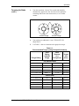
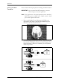
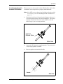
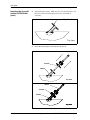
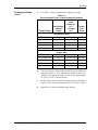
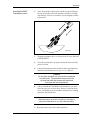
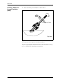
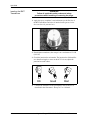
Torque the transducer to 15 to 18 ft-lb (20 to 25 N-m). DO NOT
OVERTIGHTEN.
4.
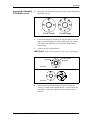
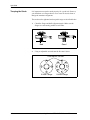
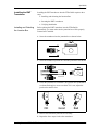
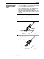
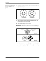
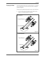
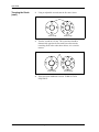
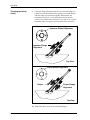
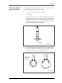
Verify the junction box is properly oriented as discussed in the
pervious section.
5.
Connect the transducer to the electronics and/or preamplifier as
described in the flowmeter’s Startup or User’s Manual.
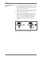
Caution!
Do not place insulation on or around the transducer
or junction box. The transducer and junction box
act as a heat sink that protects the transducer
from high and low temperatures.
6. After you install the FTPA Buffers and transducers, you must
allow the epoxy to cure for 8 hours. However, while the epoxy
cures, you should verify the transducer and buffer are working
properly as described below.
Caution!
While the epoxy cures, do not remove, re-torque or
adjust the transducer or you will crack the epoxy.
7. Repeat the above steps for the other transducer.
Verifying Installation
1. Power up the electronics.
2. Refer to Displaying Diagnostics in the flowmeter’s Service or
User’s Manual to display the up and down signal strength.
3. Record this data in the Service Record in the back of the
flowmeter’s Service or User’s Manual.
4. Verify that the signal strength diagnostics are the same or better
after 8 hours.
This completes the installation of the FTPA buffers and transducers.
Refer to the flowmeter’s Startup or User’s Manual for instructions on
obtaining flow rate measurements.
Installing Standard FTPA BWT Buffers and Transducers
2-11