1
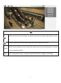
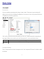
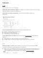
Content Safety Instruction ............................................................................................................................................................ 2 Minimum System Requirement & Product Feature.................................................................................................... 4 Minimum System Requirement .................................................................................................................................... 4 Product Feature .............................................................................................................................................. 5 Main Page ........................................................................................................................................................................ 6 Basic Setup........................................................................................................................................................ 9 Account .......................................................................................................................................................... 9 Network........................................................................................................................................................ 10 Date Time ..................................................................................................................................................... 12 Video ............................................................................................................................................................ 13 Live View......................................................................................................................................................... 16 Video ............................................................................................................................................................ 16 Camera Setting ............................................................................................................................................. 16 PT Setting..................................................................................................................................................... 18 Playback .......................................................................................................................................................... 20 Client PC ...................................................................................................................................................... 20 Network Storage .......................................................................................................................................... 21 Local Storage ............................................................................................................................................... 21 Event................................................................................................................................................................ 22 Event Server ................................................................................................................................................. 22 Event List ..................................................................................................................................................... 22 Motion Detection ......................................................................................................................................... 24 Tampering Detection .................................................................................................................................... 24 Schedule ....................................................................................................................................................... 25 System ............................................................................................................................................................. 25 Maintenance ................................................................................................................................................. 25 Date Time ..................................................................................................................................................... 25 Security ........................................................................................................................................................ 26 Network Basic .............................................................................................................................................. 26 Network Advanced....................................................................................................................................... 26 LED .............................................................................................................................................................. 28 System Log .................................................................................................................................................. 28 1 User Manual Safety Instruction Before you use this product This product has been designed with safety in mind. However, the electrical products can cause fires which may lead to serious body injury if it is not used properly. To avoid such accidents, be sure to heed the following. Legal Caution Video and audio surveillance can be forbidden by laws that vary from country to country. Check the laws in your local region before using this product for surveillance purposes. Don't open the housing of the product Don't try to open the housing or remove the covers which may expose yourself to dangerous voltage or other hazards. Don't use the accessories not recommend by the manufacturer Heed the safety precautions Be sure to follow the general safety precautions and the “Operation Notice.” Operation Notice - Operating or storage location Avoid operating or storing the camera in the following locations: Extremely hot or cold places (Operating temperature: 0 °C to + 50 °C [32 °F to 122°F] ) Exposed to direct sunlight for a long time, or close to heating equipment (e.g., near heaters) Close to water (e.g.,near a bathtub, kitchen sink, laundry tub) Close to sources of strong magnetism Close to sources of powerful electromagnetic radiation, such as radios or TV transmitters Locations subject to strong vibration or shock In case of a breakdown In case of system breakdown, discontinue use and contact your authorized dealer. In case of abnormal operation If the unit emits smoke or an unusual smell, 2 If water or other foreign objects enter the cabinet. If you drop the unit or damage the cabinet:1 Disconnect the cable and the connecting cables. 2 Contact your authorized dealer or the store where you purchased the product. Transportation When transporting the camera, repack it as originally packed at the factory or in materials of equal quality. Ventilation To prevent heat buildup, do not block air circulation around the device. Cleaning Use a soft, dry cloth to clean the external surfaces of the device. Stubborn stains can be removed using a soft cloth dampened with a small quantity of detergent solution, then wipe dry. Do not use volatile solvents such as alcohol, benzene or thinners as they may damage the surface. 3 Minimum System Requirement & Product Feature System Requirement For normal operation and viewing of the network camera, it’s recommended that your system meet these minimum requirements for proper operation: Item Requirements CPU Minimum Intel® Core 2 Duo or higher Graphic Card 256 MB RAM graphic cards (or equivalent on-board graphic cards) RAM Minimum 1 GB of RAM,(2GB or above is recommended) Operating System Window 2000, 2003, XP, Vista or Windows 7 Web Browser Internet Explorer 8 or later Mac OS Leopard 10.5 Note: 1. If using Windows 98 or Windows ME, please install IP Installer before using WEB UI to ensure the system runs normally. 2. If not able to view the recorded video file, please install Xvid codec while installing Intelligent IP Installer. (For Windows 98, ME or 2000 server, the codec might not work properly. Please download Xvid codec 1.0 from the internet.) 3. Please keep updating the latest Windows software and service package. (Ex: Net Framework, Windows Media Player, Enhance ActiveX Security) 4 Product Features SYSTEM Resolutions H.264 / MPEG-4 / Motion JPEG: Screen Resolution Higher than 1024 * 720 pixels Compressing format H.264 / MPEG-4 / Motion JPEG Frame Rate Up to 30 fps at 1280x800 Rotation: Mirror, Flip, Mirror Flip Image settings Brightness / Contrast / Saturation/ Sharpness Overlay capabilities: time, date, text and privacy image Image snapshot Yes Video Recording Yes Full Screen Viewing Yes Digital Zoom 10x digital Audio Mobile Phone Live View Built-in microphone Audio compression: G.711 μ law, a law, and AMR Through 2.5 WAP(above 3G is recommended) Alarm Sending FTP Client / SMTP / Network Storage / HTTP Event Security Password Protection / HTTPS encryption / IP Filter Input: alarm buffer, motion detection, audio detection Output: network storage, FTP, SMTP, Pre-and post alarm buffer Alarm Buffer Supported protocols Simultaneous Connection Operating conditions Bonjour, TCP/IP, DHCP, PPPoE, ARP, ICMP, FTP, SMTP, DNS, NTP, UPnP, RTSP, RTP, RTCP, HTTP, TCP, UDP, 3GPP/ISMA RTSP Up to 10 users 0℃~ 50℃ (32℉ ~ 122℉) HARDWARE Lens F1.8, 4.0mm Megapixel board lens Local Storage Support MicroSD card IR LEDs 5 φ IR LEDs x 11 (850nm) Alarm Input / Output 1/1 Power 12V DC, 1A, Max 5W NETWORK Ethernet 10 / 100 Base T Wireless IEEE 802.11b/g/n (for P5116) 5 Main Page Toolbar of Main Page 6 Client Setting Profile View Size Protocol Video Buffer Click the drop-down menu to choose video compression mode of Live View among H.264, MPEG-4, MJPEG and H.264. Note: As long as the operating system is not able to afford loading under H.264 mode, please downgrade the mode to MPEG-4 or MJPEG. Select the desired view size of image resolution between Fit Screen and Full Screen. Select the transferring protocol among TCP, UDP, and HTTP. Turn the Video Buffer function On / Off. The Video Buffer function makes the streaming more smoothly in unsteady network environment, but might cause a little delay in live view. 7 PTZ Click the Home button and it brings you back to the center no matter what position you are at. Move the camera view to the direction that the various arrows you click on. Use the various direction arrows to steer the camera view to the required position,and name Preset it for the specified position. Patrol Before starting this function, it requires to specify Guard tour settings in the Setting 8 Basic Setup Account Account List The device default account and password setting is “admin / admin”. That means everyone who knows IP address can access the device including all configuration. It is necessary to create a new password if the device is intended to be accessed by specific ones. Click “Add” to create the accounts to the specific users. There are 1 default account and 9 accounts that you may assign 3 different viewer modes as you wish. The instruction of 3 viewer modes listed as below: It only allows the user to access to the Live View page. Viewer It allows to view the Live View page, create and modify events, and adjust certain other settings. Operator Administrator It allows the user to watch the live view and access all configurations. Anonymous Setting There is a drop-down menu for both “Anonymous viewer” and “Anonymous PTZ control” to disable or enable the function. 9 Network TCP/IP Internet Protocol Version 4 (TCP/IPv4) Obtain an IP address automatically (DHCP): If a DHCP server is installed on the network, to select this while the IP address is assigned by the DHCP server. Obtain DNS server address automatically: Select this to obtain the address of DNS server automatically. Use the following IP address: Select this option when the fixed IP address is set. IP address: Enter the IP address of the device. Subnet mask: Enter the subnet mask. Default gateway: Enter the default gateway. Use the following DNS server address: Select this when you set the fixed address as the IP address of DNS server. Primary DNS server: Enter the IP address of the primary DNS server. Secondary DNS server: Enter the IP address of the secondary DNS server, if necessary. HTTP HTTP port number: Select 80 in general situations. If you want to use a port number other than 80, select the text box and enter a port number between 1024 and 65535. When you have set the HTTP port number to a number other than 80 on the Network Setting screen in the Setup Program, access the device by typing the IP address of the device on the web browser as follows: Example: when HTTP port number is set to 2000 http://192.168.1.100:2000/ 10 Note: Reboot the IP Camera after the network setting has been made. Note: If you connect the IP Camera with your computer directly, the default network domain of camera is 192.168.1.xx PPPoE If your ISP provides Dynamic IP with authentication by username and password, type all PPPoE information in this part. When using the PPPoE function, you need to turn on the DDNS or IP Notification function at the same time. IP address: The IP address obtained at the PPPoE connecting with network. User ID: Enter the user ID for authentication necessary for PPPoE connections. Type it up to 64 characters. Password: Enter the password for authentication necessary for PPPoE connections. Type it up to 32 characters. Re-type password: Re-type the password to confirm. Obtain DNS server address automatically: Select this to obtain the address of DNS server automatically. 11 Use the following DNS server address: Select this when you set the fixed address as the IP address of DNS server. Primary DNS server: Enter the IP address of the primary DNS server. Secondary DNS server: Enter the IP address of the secondary DNS server. Note : 1. PPPoE (Point-to-Point Protocol over Ethernet): PPPoE is a network protocol for encapsulating Point-to-Point Protocol frames insider Ethernet frames. PPPoE connection is used mainly with ADSL service where individual users connect to the ADSL transceiver (modem) over Ethernet work. It also widely used in XDSL (digital affiliate line such as ADSL, VDSL or SDSL) 2. Reboot the IP Camera after the network setting has been made. 3. The IP Camera with Intelligent IP Installer can’t be founded after turning on the PPPoE and reboot. Date Time Current Date / Time It displays current time and date of IP Camera and PC that you connected, and you may select the Date/Time format as you wish in the drop-down menu. Note: If you would like the Date / Time information shows on the Live View screen, please check “Basic Setup →Video →Overlay → Overlay Type → Time Stamp ” and save the setting. Synchronization Method Keep current setting: Select this mode to keep the current date and time of this IP Camera. Synchronize with Client PC: Select this mode to keep the date and time of this IP Camera is the same as the monitoring PC. 12 Manual setting: Select this mode to adjust manually the date and time of this IP Camera. Synchronize with NTP: Specify the NTP server name and click “Update now” to synchronize the date and time of this IP Camera with those of the time server, known as the NTP server. Time Zone Time Zone: Select the Time Zone format of Greenwich Mean Time among different cities. The time display will be the same as the current date / time option. Daylight Saving Time: There are two modes to choose for setting up daylight saving time. By Date: Set the start and end time by select month, day, hour, and minute. By Week Number: Set the start and end time by select month, week, hour, and minute. Note: The NTP server (Network Time Protocol) is the time server which is an Internet standard protocol built on the top of TCP / IP. This assures accurate synchronization to the millisecond of computer clock times in a network of computers. Video Video Setting Image Image Rotated: Select the screen display “flip”, “mirror”, or “flip + mirror. Video clip format: Select RECORDING compression format H.264、MPEG-4、MJPEG、EZVuu HQ and EZVuu LQ . Profile1(H.264): H.264 provides higher compression rate than MPEG-4. Thus, H.264 can decrease the 13 bandwidth usage and further apply on 3G. However, H.264 will occupy more system resources than MPEG-4. As long as the operating system appears operating difficulties under H.264 format, please change to select MPEG-4. Profile2(MPEG-4): MPEG-4 has the advantage of sending a lower volume of date per time unit across the network (bit-rate) compared to Motion JPEG and therefore provides a relatively high image quality at a lower bit-rate (bandwidth usage). Profile3(MJPEG): Motion JPEG stream uses considerable amounts of bandwidth, but provides excellent image quality and access to every image contained in the stream. Overlay Text information can be showed on the display screen, such as Date / Time and the user-defined title. Privacy Mask Privacy Mask is an area of solid color that bans users from viewing part of monitored area. Click “Add” and a setting pop-up window comes out. A translucent rectangle is located at up left of the image, drag it to where you wish to cover and resize it. Enter a descriptive name, select the color and enable it then save. 14 Profile There are five stream profiles available for quick set-up. These settings can be adjusted and new customized profiles can be created. Each profile has a descriptive name, describing its usage and/or purpose. The profiles can be selected from the Live View page. Create a new stream profile: Click “Add” and a setting pop-up window comes out, Edit the stream profile: Click the profile you appoint to modify and click “Edit” to do the further setting. Day/Night IR Cut Filter Mode: There are 4 modes for IR cut filter to switch Auto, Night Mode, Day Mode, Schedule to make IR cut filter work based on different conditions. IR Cut Filter Switch Delay: This is interval time(by seconds) when the IR cut filter switch has been implemented till it indeed works. 15 IR Cut Filter Threshold: Dark-This is the threshold for the IR cut filter image environment being bright turning to dark. Bright- This is the threshold for the IR cut filter image environment being dark turning to bright. IR / IR cut filter schedule: The IR cut filter can be scheduled manually as you wish to turn it on, you may configure each time mode in advance in “Schedule”. Live View Video Please refer to p.13 Camera Setting View Setting A view area is a cropped part of the overview image. Each view area is treated as a video source in Live View with its own Video Stream, PTZ and Event settings. There are 4 areas can be preset and 6 various resolutions for each view area. Note: Except the View Area1 has been fixed to be full resolution, the rest of the three are available to be set to resolution you wish in the drop-down menu. 16 Image Setting Image Enhancement Brightness: The image brightness can be adjusted in the range 0-100, the a higher value produces a brighter image. Saturation: Adjust the saturation in the range 0-100, the higher value gets more colorful image. Contrast: Adjust the image's contrast by raising or lowering the value in the range 0-100. Sharpness: Controls the sharpness applied to the image in the range 0-100. A sharper image might increase image noise especially in low light conditions. A lower setting reduces image noise, but the image would be less sharp. White Balance Color Tone: 3 optional color tones(cool, real and warm), it depends on individual preference to select. Auto White Balance: This is used to adjust for the different colors present in different light sources, to make the colors in the image appear the same. The IP camera can be set to automatically identify the light source and compensate for its color. Alternatively, the type of light source can be manually selected from the drop-down menu. Exposure Setting Exposure Frequency: The default setting of lighting environment is Auto. However, you may select 50 or 60 Hz upon the lighting environment of your country. The hold current option fixes the current exposure settings Automatic exposure: You can manually set the exposure value, which ranges from 0-100(dark to bright). The default value is 25. 17 Exposure time: Select a proper exposure time according to the light source of the surroundings. The exposure times are selectable as the following durations: 1/120second, 1/60 second, 1/30 second, 1/12 second, 1/6 second, 1/3 second, and 1second. Shorter exposure time brings less light. Gain: According to the surroundings in the low light and make the range among 1-64. The higher value makes brighter image, however brings more noise at the same time. Low light behavior: This is the operation aims at low light and night mode. According to the surroundings you can manually set the preferable settings differ from the regular “Exposure Settings”. Nevertheless, the low light behavior can be scheduled up by working day, weekend, and night mode as user’s preference. Backlight Compensation: It makes the object clearer display when the image background is too bright or the object is too dark. Wide Dynamic Range Enable Wide Dynamic Range auto in different level to improve the exposure when both bright and dark areas simultaneously in the field of view of the camera. The level goes from 1-8, the larger number brings stronger influence, and the default is off. Noise Reduction Select the period you wish the noise reduction being executed in the drop-down menu, there are working day, weekend, and night mode. PT Setting Patrol Settings You may set the speed of digital pan/tilt, and also speed for preset/patrol. The range goes 1-100(slow to fast). Control Panel Click the arrow button of the direction you want the IP camera to move. The calibration makes PT camera go the tour as booting up. Preset Position Name position you prefer and click “add”, you can click “go” to make sure if the preset position has 18 been written in, as well as the home position, which the device faces to when the power is turned on. Guard Tour Click “add” , name the tour first then add in the preset position you desired to form the tour. You can manually set the PTZ speed and the interval time. PT Control In this section, it provides Pan, Tilt, Auto Pan speed control setting. 19 Playback Client PC This is for uploading the recorded file saved in the PC and play back to see the video. ❸❷❶ ❹❺ ❻ 20 ❼❽ ❾ ❿ ❶ Click it to upload the recorded file in the PC ❷ Click it to stop the current video ❸ Click it to pause the playing video ❹ Click it to slow down the playing speed ❺ Click it to speed up the playing speed ❻ It displays the current playing video length ❼ It displays the whole video length ❽ It displays the current video speed ❾ Click it to adjust the volume of video and mute ❿ Click it to make digital zoom Network Storage Network storage provides the storage function for saving image files to the specified computer and folder connected with the operating computer. Before using this function you must go to Event Server in Event to configure all settings and make the recording file saved here. Local Storage Memory card provides local storage function for saving image files to the specified SD card in your camera. This function can be enabled only when you insert SD card to the camera and the SD/SDHC card works well. Before using this function you must go to SD card in Event to configure all settings and make the recording file saved here. 21 Event Event Server Event Server Click “Add” to create a event server then the setting page pops up. Name it, select your network type put on the storage location. This is optional to create the password for certain group to use it. Then click the “Test” button to see if it works, it will show the information on the pop-up window to see your setting if has been made successfully. 3 types of event transmission offered to select. There is a range 0~7 seconds can be selected individually for pre-event and post-event. 3 suffix options for naming image file by Name, Date Time and Sequential Number. SD Card Make sure to insert the SD Card first then click “on”. Create a folder name for event server in SD Card. Optional selection for overwrite the previous file or not, if not, you may set a warning when the capacity below the following percentage:5%, 10%, 25% and 50%. Event List Event List 22 General Name the event file and make it on or off. Trigger You may activate the following trigger types as you wish depends on various conditions: Motion Detection: Click it on for using Motion Detection function as a sensor. You must configure motion detection function before taking this as the trigger. Set minimum time interval between 2 triggers, and choose the desired detection area. The detection type individually stands for the following meanings: Start: The trigger would be activated when the target object starts to move. Stop: The trigger would be activated when the target object stops to move. Start-Stop: The trigger would be activated during the target object starts to move till it stops. Audio Detection: Click it on for using Audio Detection function as a sensor. You must configure audio detection function before taking this as the trigger. Set minimum time interval between 2 triggers. The detection type stands for the following meanings individually: Start: The trigger would be activated when the sound being made. Stop: The trigger would be activated when the sound being cut off. Start-Stop: The trigger would be activated during the sound being made and cut off. Periodical: This can be set the certain period(by minute) to start the trigger. On boot: The event is triggered when the IP Camera has been started over . Capacity Warning: This is triggered when SD Card capacity is be below the value you set. Network Link Down: The event is triggered when the network get disconnected. IP Notification: The event is triggered when the network being restarted or the IP being changed. And there are optional network types to select, such as DHCP、Static IP and PPPoE. Action There are multiple choices for action taking which is optional for user to select all of them or part of them: Send Image、Send Notification、PTZ Action or Night Mode. Send Image: You may set up where the image sent to, options like event server and SD card. You must configure it first, please refer to Event Server. Send Notification: Firstly got to HTTP server configure the HTTP server URL, port, User ID, Password, and Proxy server settings. Note: The setting of URL should be the same as CGI. PTZ Action: Firstly configure the PTZ to set up the preset positions and tour you desired. You may select to return to the last position after the event being triggered. 23 Night Mode: You may set up this action being activated continually while the event triggered or continually every period(by second) interval. Note : Only Motion Detection excludes Night Mode Schedule You may set up the event schedule as “always” or scheduled by working day, weekend or night mode. You must configure schedule before using it. Scheduled Recording General Name the recording file and make it on or off. Action File Size: You can manually write in the file size as the suggested range. Cyclic Size: You can manually write in the cyclic size as the suggested range. Schedule You may set up the event schedule as “always” or scheduled by working day, weekend or night mode. You must configure schedule before using it. Motion Detection Add the motion detection zone and name it, you can adjust the zone of detection with the mouse. There are 10 for detection zone at maximum. The bar on the top of motion detection area is red when the alarm is triggered. Threshold: Set the threshold of the alarm in the motion detection zone. The higher threshold is, lesser detections can be triggered. Sensitivity: Set the sensitivity for motion detection zone. The higher sensitivity is, the more sensitive it gets. Tampering Detection Select “on” if you want to activate the tempering detection. Trigger Duration: This setting is set for the trigger will be started for the duration of tampering lasts you configure. The duration range is from 5 seconds to 900 seconds. 24 Schedule The schedule is made for Event List to set the recording period. There are already 3 modes(Working Day、 Weekend and Night Mode) has been set for user, there are 7 more modes are available to set manually. System Maintenance Restart Restart button is for reboot the IP Camera digitally, you may reboot the camera manually or automatically. Click “on” and shows two modes for user to reboot the camera automatically. Sequential Mode offers the selection that how many days you would like to reboot, 7 days at most. Schedule Mode is able to select the certain day and time to reboot. Backup/Restore Default: Click this button to recover this IP Camera to the factory default setting. A confirmation dialogue will appear and then click “OK” to execute. The network indicator on this IP Camera will start to blink. This IP Camera will reboot automatically after completing adjustments to the default setting. Don't turn off this IP Camera until the device reboots. Furthermore, the IP and Date Time that are already set up can be fixed. Backup: You can save the setting data of this IP Camera into a file. Click “Save” and follow the instructions on the browser to save the setting data file to the location you specified. Restore: Download the saved setting data of this IP Camera. Click “Browse” and select saved file. Click “OK” and this IP Camera is adjusted according to the loaded data and then restarted. Firmware Upgrade Update the device software. Click “Browse” and select the file for updating. A confirmation dialogue will appear. Click “OK” to start. This IP Camera will reboot upon completion. Date Time Please refer to p.12 25 Security Account Please refer to p.9 IP Address Filter Once enabled it, the listed IP address are allowed or denied access to the product. Add the IP Address that you’d like to allow or deny and select allow or deny from the list and save it. HTTPS HTTPS is a URL scheme used to indicate a secure HTTP connection. It is syntactically identical to the http:// scheme normally used for accessing resources using HTTP. Using an https: //URL/ with a different default TCP port (443) and an additional encryption / authentication layer between the HTTP and TCP. You can use the IP camera through HTTPS easily by using https:// instead of http://. Create & Install: Create a self-signed certificate for HTTPS to recognize. Installed Certificate: Display or remove the properties of the installed certificate. HTTPS Connection Policy: Set HTTPS connection policy for different level of users. To use the HTTPS encryption, please set up “Create self-signed certificate” for the first time you use the HTTPS function, and then set up the connection policy for different users. Note: When enable HTTPS with RTSP on mode, the IP Camera only protect the setting such as username and password and do not protect video and audio. When enable HTTPS with RTSP off mode, the IP Camera will protect all setting including video and audio. Network Basic Please refer to p.10 Network Advanced RTSP 26 General RTP Port Range: The default value of port range is 5000 ~ 7999 and can be changed from 1124 to 65534. RTSP Port: The default value is 554. If the IP Cameras connected with router and installed outside are over 2 sets and all of them need support RTSP, please fill the value in the blank space in the range from 1124 to 65534. RTSP Configuration Configure the RTSP by profile, then enable or disable the authentication. Multicast Status: This can be enabled or disabled the multicast. Access Name: This will be shown and changed along with the profile you select. Multicast Address: Specify the multicast server address. Video / Audio Port: Specify the transmission port number of the video data, from 1124 to 65534. Time to Live: Set the maximum TTL that multicast can pass through. The default value is 15. UPnP If you have a Router to access to internet and the Router supports UPnP IGD function, you need to turn on the UPnP Port Forwarding function. HTTP port: Enter the HTTP port number and default HTTP port is 80. SSL port: Enter the SSL port number and default SSL port is 443. RTSP port: Enter the RTSP port, default value is 554 for computer view. Note : UPnP (Universal Plug and Play): UPnP is a set of computer network protocol. It allows devices to connect seamlessly and simplify the implementation of networks in the home and corporate environments. Bonjour Bonjour, also known as zero-configuration networking, enables automatic discovery of computers, devices, and services on IP networks. Bonjour uses industry standard IP protocols to allow devices to automatically discover each other without the need to enter IP addresses or configure DNS servers. Device Name: Enter Device Name you wish. Note: How to use Bonjour in your Windows Browser UI? Please check the link below: http://www.apple.com/support/downloads/bonjourforwindows.html 27 DDNS DDNS is a system which allows the domain name data held in a name server to be updated in real time. The most common use for DDNS is allowing an internet domain name to be assigned to a computer with a varying / dynamic IP Address. This makes it possible for other sites on the internet to establish connection to the machine without needing to track the IP Address themselves. Server name: Choose the DDNS Server from the list. User ID: Enter the user ID for authentication necessary for DDNS connections. Type it up to 64 characters. Password: Enter the password for authentication necessary for DDNS connections. Type it up to 32 characters. Re-type password: Re-type the password to confirm. Host name: Enter the host name that is registered to the DDNS server. Periodical Update: Update your DDNS information periodically. LED This is optional for user to select to show the LED indicator or not to as the IP Camera is turned on. What benefit it gets when LED off is it’s not easily to be aware when somebody sneak in the space where the camera installed, especially at the darkness. System Log System Log Enable the remote log to let the log being saved in the remote server in case that the camera being cut down. Put on the server name and select the sever port and save it. 28