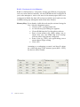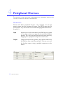
1
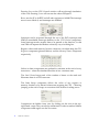
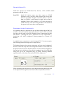
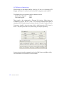
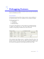
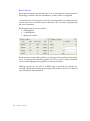
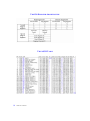
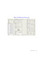
USER MANUAL
NATHANIEL THWAITES -M CGOWAN
ABBREVIATIONS
Whilst this document is aimed at readers with a Computer Science background,
this list of acronyms is intended to help those without the required depth of
hardware knowledge.
CPU
Central Processing Unit
DJNZ
Decrement and jump if not zero (instruction used for looping)
EPROM Erasable -Programmable Read Only Memory (reusable ROM)
2
GUI
Graphical User Interface
IC
Integrated Circuit (or microchip)
NMI
Non-Maskable Interrupt
PIO
Parallel Input / Output – Z80 family microchip providing I/O
RAM
Random Access Memory (volatile, temporary storage)
ROM
Read Only Memory (non-volatile, permanent storage)
ZIM User Manual
CONTENTS
1
INTRODUCTION
4
2
GETTING STARTED
5
Downloading ZIM
5
Simulating execution
5
MEMORY C ONFIGURATION
7
ROM
7
RAM
8
Memory -Mapped I/O
9
Memory -Mapped Serial I/O
9
PERIPHERAL DEVICES
10
Discrete I/O
10
Discrete Serial I/O
11
Peripheral Screen Components
11
DEBUGGING FEATURES
13
Watch Points
13
Break Points
14
LOGGING
15
Instruction Tracing
15
I/O Logging
15
7
SAVING YOUR C ONFIGURATION
16
8
COMPATIBILITY
17
3
4
5
6
ZIM User Manual
3
1
Introduction
The Department of Computer Science
The University of York
York, YO10 5DD
United Kingdom
24th February 2004
Dear User,
Welcome to ZIM – The Z80 Machine Simulator.
ZIM is a fully featured Z80 CPU Simulation tool designed as an aide for students
studying modules involving the Z80 assembly language.
ZIM has been designed with users in mind – incorporating an advanced GUI, allowing
the visualization of code simulation in real-time.
Extensive debugging features are also provided:
Advanced break-points and watch-points,
Instruction Tracing
I/O logging
The ability to request interrupts from the GUI
and much much more…
ZIM has been designed to be intuitive, so those with knowledge of a Z80 system
should be able to make full use of all the features immediately. For the less informed
reader, this manual will lead you through the basics, and introduce you to the more
advanced features.
All comments and queries are gratefully received.
N. Thwaites-McGowan
[email protected]
4
ZIM User Manual
2
Getting Started
THIS SECTION COVERS GETTING HOLD OF AN AUTHENTIC COPY OF ZIM, INSTALLING
AND RUNNING IT ON YOUR PC, AND SIMULATING SIMPLE PROGRAMS.
DOWNLOADING AND I NSTALLING ZIM
ZIM is a Java application, and is available as a download for Windows,
Linux and the MacOS platforms.
Visit http://www-students.cs.york.ac.uk/~njtm100/ for a copy of ZIM. You
will also require the Java Runtime Environment, which can be obtained
direct from sun at http://java.sun.com.
By far the best way of running ZIM is through the Java Web Start facility.
Having installed the Java Runtime Environment, you will also have
automatically installed Java Web Start. This enables you to simply click on
the “Launch ZIM” link on the website to run the application.
Downloading, version updating and local storage for when you want to
run the application offline, are all handled automatically by JWS.
S IMULATING EXECUTION
When you’ve successfully downloaded a copy of ZIM, or accessed ti
through Web Start, you’re ready to begin simulating code.
ZIM’s initial state is that of a fairly standard Z80 Machine. It has a RAM
module (at 0x4000 – 0x8000), a memory-mapped input device (at 0x8000 –
0xC000), and a memory-mapped output device (at 0xC000 – 0xF000). The
remaining memory area is reserved for a ROM device containing your
program code.
Use the File menu and Open | Program to select your Z80 binary
executable. It will be configured as a ROM device starting at 0x0000. The
contents of the ROM are viewable by clicking on the ROM button
corresponding to your device in the memory-map (a second
memory -viewer is created displaying the ROM data).
ZIM User Manual
5
Pressing S TEP on the CPU Control window will step through simulation
of the code. Pressing S TART will execute the code at full speed.
RESET sets the SP to 0xFFFF and all other registers to 0x0000.The interrupt
most is set to Mode 0, and interrupts are disabled.
Interrupts can be requested through the use of the INT (interrupt) and
NMI (no n-maskable interrupt) buttons on the CPU Control component.
Some interrupt modes require data to be passed to the data bus, in this
case ZIM will request the data-bus values by way of a dialog box.
Register values and memory location values are viewable using the CPU
Registers component (pictured below) and the Memory Viewer component
respectively .
Values in these components are updated in real-time at the end of every
instruction – when the simulated machine is in a consistent state.
The Stack Viewer keeps track of the number of items on the stack and
illustrates them in a LIFO structure.
The State Setup component allows the value of any register or
memory -location to be altered in-between stepping the CPU – allowing
jumping to the end of loops, or correction of the results of coding errors.
Components are hidden from view by clicking on the cross in the top
right hand corner. They can also be minimized. In order to make a hidden
component visible again use the View menu.
6
ZIM User Manual
3
Memory Configuration
THIS
SECTION COVERS ADVANCED CONFIGURATION OF THE MEMORY -MAP
ASSOCIATED WITH THE SIMULATED Z80 CPU.
ROM – READ O NLY MEMORY
ROM is traditionally the storage medium of choice for program code. It is
non-volatile and read-only – the code is protected. ZIM has the ability to
simulate ROM devices within the memory map – protecting the contents
from any memory -writing. Data can be loaded into a simulated ROM
device in two ways.
File | Open
This method was illustrated in Section One and creates a
ROM chip the size of your code with a base-address of
0x0000. This is by far the easiest way to load programcode into the simulator.
Memory Map If not already visible this tool may be activated using the
View | Memory Mapmenu option.
• Click on ADD – top right hand side.
• An Add Memory Space dialog box appears.
• Choose ROM from the Type drop-down selector.
• Click to Choose your program file
• Enter a base-address (e.g. 0000), taking care to
ensure that your new ROM chip won’t overlap
with any other chips already configured.
• Click ADD.
Assuming no overlapping occurred, and that all values
are within the range of the memory-space (0000 – FFFF),
the device will be created.
As a helpful debugging aide, if you’re making frequent
changes to your binary code, a refresh option is provided.
After adding a ROM module, the ADD button changes to
read Refresh. A single click of Remove – next to your ROM
in the memory -map, and then a click of Refresh will
reload the modified code from the file into memory.
ZIM User Manual
7
RAM – RANDOM ACCESS MEMORY
RAM is volatile memory – temporary storage space. Before your program
code can write data into memory, an area of RAM must be configured. If
your code attempts to write to an area of the memory-space that is not
configured as RAM, the data will not be successfully saved, and won’t be
available during any subsequent read of that same location.
Memory Map If not already visible this tool may be activated using the
View | Memory Mapmenu option.
• Click on ADD – top right hand side.
• An Add Memory Space dialog box appears.
• Choose RAM from the Type drop-down selector.
• Enter a base-address (e.g. 0000), taking care to
ensure that your new RAM chip won’t overlap
with any other chips already configured.
• Enter a size (e.g. 3FFF), once again taking care to
ensure that no chips overlap.
• Click ADD.
Assuming no overlapping occurred, and that all values
are within the range of the memory-space (0000 – FFFF),
the device will be created.
8
ZIM User Manual
MEMORY-MAPPED I/O
In addition to ROM and RAM devices, memory-mapped I/O devices can
also be configured. These represent peripheral devices that can be
accessed through standard memory instructions . They are created in
exactly the same manner as RAM devices – see above. Whilst memory mapped I/O devices can encompass many memory -locations, each
memory -location within one will act in exactly the same manner.
i.e. If a device active from 4000 – 5FFF then
a write to 4015 will have the same effect as a write to 5F3A
Input
Input devices can be read from by the Z80, but not written
to. Any data written to an input device (much like ROM) is
ignored. The user can feed data into an input device by
mapping it to a peripheral component on the screen
(see Section Four).
Output
Output devices are the opposite – they can be written to by
the Z80, but data cannot be read back. The user can view
the last byte output, using a periphal component on the
screen (see Section Four).
MEMORY-MAPPED S ERIAL I/O
Serial I/O devices are bi-directional memory -mapped I/O devices, which
exhibit similar properties to RAM devices.
Serial I/O
Serial I/O devices map any data output to COM1
(Windows only), and any read requests are served with
data inbound on COM1. Program execution halts to wait
for data on COM1 if a read request is made, and no data is
available.
Data is queued, so if 5 bytes are sent to COM1 and only 2
are read using the Z80, 3 will remain in the queue for the
next three read operations.
ZIM User Manual
9
4
Peripheral Devices
THIS
SECTION COVERS ADVANCED CONFIGURATION OF PERIPHERAL DEVICES THAT
CAN BE ATTACHED TO THE SIMULATED Z80 CPU.
DISCRETEI/O
Discrete I/O allows peripheral devices to be mapped, not into the
memory -space, but into a separate I/O space. The Z80 I/O space has 256
locations (00 – FF), and devices are accessed through special instructions –
IN and OUT.
10
Input
Input devices can be read from by the Z80, but not written
to. Any data written to an input device (much like ROM) is
ignored. The user can feed data into an input device by
mapping it to a peripheral component on the screen.
Output
Output devices are the opposite – they can be written to by
the Z80, but data cannot be read back. The user can view
the last byte output, using a periphal component on the
screen .
ZIM User Manual
DISCRETE SERIAL I/O
Serial I/O devices are bi-directional I/O devices, which exhibit similar
properties to RAM devices.
Serial I/O
Serial I/O devices map any data output to COM1
(Windows only), and any read requests are served data
inbound on COM1. Program execution halts to wait for
data on COM1 if a read request is made, and no data is
available. Data is also queued, so if 5 bytes are sent to
COM1 and only 2 are read using the Z80, 3 will remain in
the queue for the next three read operations.
PERIPHERAL S CREEN C OMPONENTS
As explained above, an input device can only be read from by the Z80, not
written to. For such a device to be useful, the user must be able to provide
the data which is read by the Z80. Periphal Screen Components provide
that feature – allowing the user to input data or view output data –
interfacing with either configured memory-mapped or discrete I/O
devices.
A periphal screen component is created using the File | New menu option,
and choosing between an input or an output device.
The binding between the screen component and the actual configured
device is set in the Setup tab on the component itself. Use one of the two
drop-down menus (one for discrete devices, one for memory-mapped) to
choose the device to bind to. Once this is completed, any one of the tabs
along the top of the component may be chosen, allowing different
representations of the data to be used (ASCII, Hex, Lights etc).
When inputting data, the enter key must be pressed after placing the data
in the input box. This updates the cached value ready for the next read.
ZIM User Manual
11
LCD DISPLAY S IMULATOR
ZIM includes a simulated LM016, which is a 2 line x 16 character LCD
display by Fujitsu. It can be found on the SBC computers used in MCP.
The display has two registers used to interface with it:
The Control Register
0xB8
The Data Regster
0xB9
These need to be configured as Discrete I/O devices. When they are
available as devices, the File | New | LCD Display command will create a
simulated LCD Screen bound to those devices. No other Peripheral Device
Component should be bound to view 0xB8 or 0xB9 when the LCD Screen is
active – they will prevent the LCD from reading the outputs effectively.
Instructions giving the command set for the LM016 are available widely
on the internet or on the MCP course website.
12
ZIM User Manual
5
Debugging Features
THIS
SECTION COVERS THE
BREAK
AND
WATCH -POINT
FEATURES AVAILABLE FOR
DEBUGGING Z80 P ROGRAM CODE.
W ATCH POINTS
Watch-points provide the ability to keep a watch on various attributes of
the simulated machine. They are configured via the watch-point manager.
Watches may be placed on
§ 8-bit Registers
§ 16-bit Registers
§ Memory Locations
As the value of the attributes on watch changes, the watch-point manager
is updated, and displays the new data. This enables quick and easy
visulation of a large range of attributes in the same screen area.
If, for example a loop is being executed – or perhaps a loop within a loop – the
invarient and varient values may be spread out between registers and
memory locations. If all relevant locations and registers are placed on watch,
the execution and progression of the loop become much more visible.
ZIM User Manual
13
BREAK POINTS
Break-points operate in much the same way as watch-points, except instead of
displaying a current value for all attributes, a match value is configured.
At the end of every instruction execution this match-value is compared to the
curent value. If a successful match is detected, CPU execution is paused and
the user is informed.
Break-points may be set on values in
§ 8-bit Registers
§ 16-bit Registers
§ Memory Locations
Break-points are especially useful for executing code in fast-execution mode
up to a certain point (matching against the PC) or until a certain condition
occurs (matching against any register or memory location).
Halting execution at the end of a DJNZ loop is possible for example, by
creating a break-point matching the register B to 0x00 (or 0x01 if you want to
step through the last interation).
14
ZIM User Manual
6
Logging
THIS SECTION COVERS THE ABILITY TO LOG BOTH
OVER A PERIOD OF TIME TO A LOG FILE.
EXECUTED INSTRUCTION S AND
I/O
I NSTRUCTION TRACING
Instruction tracing enables a log file to be built containing a list of all the
instructions executed during the logging period.
File | Save | Set Instruction Trace File
This command sets the instruction trace file and enables intruction tracing. Log
| Trace subsequently enables or disables instruction trace logging. The log file
contains an instruction on each line.
File | Save | Set Message Log File
This command sets the message log file – which logs the contents of the
Messages pane – and enables message logging. Log | CPU Messages
subsequently enables or disables message logging. The log contains all the
instructions executed along with the state of the CPU after each one. FILE.
I/O LOGGING
I/O logging saves the values of all configured outputs, with an entry being
created every time any of the outputs changes value.
File | Save | Set I/O Log File
This command sets the I/O log file. Log | I/O subsequently enables or disables
I/O logging. The log contains a column containing the number of tStates since
execution began (representing time – 1 tState is equal to 250ns) and one
column representing every configured output device.
ZIM User Manual
15
7
Saving your Configuration
THIS
SECTION COVERS THE ABILITY TO SAVE YOUR MEMORY-MAP AND I/ O DEVICE
CONFIGURATION TO A FILE, AND RESTORE IT AT A LATER DATE.
S AVING YOUR CONFIGURATION
The facility to save the current configuration of ZIM covers
• Memory-mapped devices (but not ROM)
• Discrete I/O devices
Use File | Save | Current Configuration
Choose a directory and filename, and click Save.
LOADING A PREVIOUS C ONFIGURATION
Use File | Open | Previous Configuration
Every device but ROM devices will be restored as before. The screen
layout however, and log file settings will remain set as default.
16
ZIM User Manual
8
Compatibility
THIS SECTION COVERS THE INSTRUCTION SET COMPATIBILITY OF ZIM.
Z80
ZIM simulates every documented instruction included in the Zilog Z80 CPU.
Z180
ZIM simulates the following instructions
• MLT rr
Multiply
• IN0 r, (n)
Input
• OUT0 (n), r
Output
The input and output instructions behave as the input and output instructions on a
standard Z80.
(The Z180 has three I/O device spaces, two internal, and one external. IN0 and
OUT0 are used for interfacing with the internal I/O spaces. As ZIM does not
support internal I/O spaces, IN0 and OUT0 will interface with any device
configured as a Discrete I/O device.)
ZIM User Manual
17
T HE Z80 R EGISTER ARCHITECTURE
T HE ASCII T ABLE
18
ZIM User Manual
ZIM – T HE Z80 MACHINE SIMULATOR
ZIM User Manual
19
Copyright © 2003-2004 by N. Thwaites-McGowan
The right of Nathaniel Thwaites-McGowan to be identified as the Author of
the work as been asserted by him in accordance with the Copyright, Designs
and Patents Act 1988.
All rights reserved.
20
ZIM User Manual