1
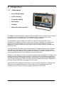
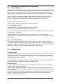
Time Electronics
1024 DC Current Calibrator
With Null Measuring Facility
Technical Manual
V1.1 20/04/09
Time Electronics Ltd
Botany Industrial Estate, Tonbridge, Kent, TN9 1RH
Tel: +44(0)1732 355993 Fax: +44(0)1732 770312
Email: [email protected]
Web Site: www.TimeElectronics.com
2
C ontents
1.
2.
Introduction ............................................................................................................ 3
1.1.
General Description................................................................................................ 3
1.2.
Specifications ......................................................................................................... 4
Operation ................................................................................................................ 5
2.1.
Front Panel Controls .............................................................................................. 5
2.2.
Operating Procedures and Precautions ................................................................ 7
2.2.1.
2.2.2.
2.3.
2.4.
Output Noise ........................................................................................................... 7
Mains Power Unit .................................................................................................... 9
2.4.1.
2.4.2.
2.4.3.
3.
Chopper amplifier module ....................................................................................10
3.1.1.
3.1.2.
Description .................................................................................................................. 10
Module replacement ................................................................................................... 10
Recalibration ........................................................................................................ 11
4.1.
Repairs ...................................................................................................................11
4.2.
Recalibration ..........................................................................................................11
4.2.1.
4.2.2.
5.
Type PU2 ...................................................................................................................... 9
Constructional details PU2 ........................................................................................... 9
240V to 110V conversion ............................................................................................. 9
Constructional Layout Details ............................................................................ 10
3.1.
4.
Normal Operation ......................................................................................................... 7
Overload conditions ...................................................................................................... 7
Calibration Procedure ................................................................................................. 12
Linearity ...................................................................................................................... 12
Guarantee & Servicing......................................................................................... 13
All Time Electronics' instruments are subject to continuous development and improvement and in
consequence may incorporate minor detail changes from the information contained herein.
1024 Technical Manual
2
3
1. Introduction
1.1.
Description
•
Up to 100mA output
•
0.02% accuracy
•
10 ppm/hr stability
•
Null facility
•
Portable
•
Battery & mains operation
The 1024 is a solid state battery powered instrument which is easily portable and convenient
for laboratory, field, or industrial use. It incorporates many of the well-proven circuit
techniques of the Time Electronics Type 1010 DC Voltage Calibrator.
The null balance system enables the 1024 to be used for making accurate current
measurement in addition to its basic function as a calibrator. Operation is by backing the
current source output against the current to be measured, with the difference being
displayed on a sensitive centre zone null meter. At the null point, there is no voltage drop
across the 1024.
The 1024 employs a precision aged reference diode as a basic reference source. Excellent
zero stability is ensured by the use of a high performance FET chopper amplifier system.
Precision metal film resistors with temperature co-efficients of less than 10 ppm per ºC are
used to maintain the accuracy and stability of the initial calibration.
Operation is from battery or mains. A front panel indicator that also serves as a supply on-off
display monitors the battery supply condition. A minimum line on the indicator shows when
the batteries should be recharged. Charging is performed by its own internal charger/power
supply. Simply plugging the 1024 into a mains supply will charge the batteries. Operation of
the 1024 may be continued when plugged into the mains.
Applications include calibration and testing of current sensitive transducers; calibration and
linearity tests on digital and electronic current meters; and semiconductor parameter
measurements e.g. diode conduction voltages at specified current levels.
1024 Technical Manual
3
4
1.2. Specifications
Output:
0-100mA in 5 ranges
0-99.999mA in 1uA steps
0-9.9999mA in 100uA steps
0-999.99uA in 10nA steps
0-99.999uA in 1nA steps
0-9.9999uA in 0.1nA steps
Accuracy:
+/- 0.02% of setting, +/- 0.005% of range, +/- 0.2nA
Voltage Capability:
15V with new batteries or mains power
(11V with minimum allowable battery level)
Regulation:
Load: Better than 5ppm per Volt
Supply: Better than 5ppm per Volt
Output polarity:
Positive or negative switch selected. A centre off position
provides an open circuit on the output terminals
Out of limit warning:
A front panel indicator provides a warning of insufficient
drive voltage
Output stability:
Less than 30 ppm per °C (0°C to + 50°C)
Less than 10 ppm per hour at constant temperature
Less than 75 ppm per 6 months
Output noise:
100, 10 and 1mA ranges: less than 5ppm of full scale
100 and 10uA ranges: less than 10 ppm of full scale +/- 0.1nA
Null sensitivity:
Adjustable from +/- 25 mA to +/- 25uA FSD via front panel
control. Maximum resolution is 0.5uA.
Power supply:
Time Electronics power unit type PU2 which is housed in the
rear of the 1024. The PU2 will power the 1024 direct from the
mains or an internal rechargeable battery. The battery is
automatically charged when mains power is connected.
Dimensions:
L 220mm x H 160mm x D 200mm
Weight:
3.3 Kg
1024 Technical Manual
4
5
2. Operation
Despite being a precision instrument the 1024 does not require special operating conditions
or procedures. Its robust construction and stable solid state circuitry enables it to be used in
nearly all applications with only the normal operating precautions.
k
i
f
g
j
h
e
b
a
d
c
2.1. Front Panel Controls
a) Output terminals
The 1024 output current is from two front panel terminals which are suitable for wire
compression or 4mm plug insertion. The output current will flow from the + (red) terminal
when the polarity switch is ‘normal’.
b) Case terminal
The case terminal is connected only to the instrument case and is isolated from the circuitry.
The case provides an overall electrostatic screen for the 1024 and can be earthed as
required to improve rejection of noise pick-up.
c) Supply ON-OFF
A miniature toggle switch interrupts the supply line to the circuitry. Indication of supply ‘on’
or ‘off’ condition is provided by the battery level indicator.
d) Output Polarity
A change-over toggle switch enables the output current polarity to be reversed. A centre ‘off’
position provides an open circuit on the output terminals.
1024 Technical Manual
5
6
e) Battery Level
The battery (or mains power supply PU2) output is continuously monitored on a front panel
indicator which also serves as a supply ‘on-off’ indication. A minimum mark indicates when
the batteries need recharging.
f) Range
One of the five output ranges can be selected.
g) Digit Switches
A 5-decade thumbwheel switch enables the output current level to be set with a resolution of
0.01% of full scale.
h) Voltage Limit
An L.E.D. indicator shows when the 1024 is unable to supply sufficient drive voltage to
maintain the set output current.
Example: The 1024’s maximum drive voltage (voltage capability) is 15 Volts. This means
that it is able to supply a current of 1mA into 15K ohms but NOT 1mA into 16K ohms. In the
latter condition the voltage limit indicator would display.
The above is an example and applies similarly for any product of current and load
resistance that exceeds 15 volts. Non-resistive loads are still bound by the same output
voltage limit with the indicator displaying when the voltage at the output terminals reaches
about 15V.
Note:
When the 1024 is operated from partly discharged batteries, the voltage limit is reduced to a
minimum of about 10V for nearly fully exhausted cells. The battery level indicator gives a
clear indication of battery state.
i) Null Meter
Scaled 0 to 25 for displaying the difference current when the 1024 is used in the null mode.
j) Sensitivity Control
A continuously variable control for adjusting the null meter sensitivity, range of adjustment is
from 25mA minimum (fully anticlockwise) to 25uA maximum (fully clockwise).
k) Source - Null Switch
A two position toggle switch which selects the mode of operation. In the SOURCE position
the 1024 operates as a current source while the null position allows measurement of
current.
Important Note:
Under no circumstances must an additional voltage be connected in series with the
1024 output in an attempt to increase the voltage capability. This practice will cause
damage to this 1024’s output circuitry.
Under certain conditions the voltage capability can be increased to a maximum of
50volts. This requires special circuit modifications and is only applicable to certain
ranges. Please consult Time Electronics (or their authorised dealer) for information.
1024 Technical Manual
6
7
2.2. Operating Procedures and Precautions
2.2.1. Normal Operation
Operation of the 1024 is self-explanatory from the front panel controls and specifications. It
is important to understand the 1024’s voltage capability and voltage limit indicator to ensure
that your requirement is within the limit. It is also important to read section the section on
output noise if your requirement is for current levels of less than a few tens of microamps.
When the 1024 is operating from batteries and required to supply currents in excess 10
10mA it is important to check the battery condition with the load connected since the
battery’s condition may be adequate for small output currents but not large ones.
Measurement of an unknown current:
1) Select ‘NULL’ position on the front panel function switch.
2) Select ‘NORMAL' output.
3) Adjust ‘SENS’ for minimum sensitivity (fully anticlockwise).
4) Select range consistent with current to be measured.
5) Connect the unknown current to the terminals in the same polarity i.e. unknown current
flows into the + Ve terminal.
6) Adjust digit switch and sensitivity control for null balance on meter as required.
7) When balance at required sensitivity is reached the unknown current is equal to the digit
switch setting.
2.2.2. Overload conditions
The 1024 can withstand indefinitely either short or open circuit on the output terminals.
Overload conditions can easily result if any attempt is made to drive current into the 1024 by
applying a voltage to the output terminals. In most cases this will cause the output fuse (See
Section 2.5) to blow but can still cause damage to the output circuitry.
2.3. Output Noise
a) Inherent Noise
The electrical noise on the output current consists of chopper intermodulation, thermal noise
and random variations. These are generated inside the 1024 and originate from the active
circuitry. At current levels of greater than about 1mA the noise fluctuations are those of the
accurate voltage reference circuitry.
At currents below a few hundred microamps it becomes difficult to differentiate between the
1024 inherent noise and picked-up noise (see Section 2.3b)
b) Noise Pick-up
In addition to the inherent noise from the 1024 circuitry the output can contain fluctuations
which originate from outside sources.
As with voltage signals the effects of noise on current signals are usually measured as a
fraction of the signal (in % or PPM) and in general this fraction becomes larger as the signal
level is reduced.
A good deal of care must be taken in attempting to understand the cause an effect of noise
pick-up on precision current sources such as the 1024 and it is not proposed that this
manual should cover them in detail.
1024 Technical Manual
7
8
It is important when confronted with a problem of noise pick-up to stop and think logically
about the cause and effect - a good deal of time can be wasted by indiscriminate screening
and earthing!
This is particularly important when dealing with current signals since many of the effects are
the exact opposite from those for voltage signals e.g. earthing one side of a voltage signal
may reduce the noise pick-up but earthing the same side of a current signal may increase
the pick-up. Before looking at possible sources of noise pick-up it is also important to
consider the way in which the presence of noise is being detected.
In many cases it will appear as an incorrect readout. Special care must be taken if additional
equipment (such as an oscilloscope of DVM) is connected for the detection of noise - there
is a possibility that this can introduce further noise.
Two of the more common causes of noise pick-up are discussed below. The actual level of
pick-up cannot be predicted and will depend on a number of factors.
(1) 50-60 Hz Mains Supply: This is probably the largest single source of noise pick-up. The
noise from this source can be divided roughly into two parts.
a) 50-60 Hz Signal pick-up - is generally caused by the close proximity of
unscreened mains cables or mains powered equipment. The effects of this type
of noise can usually be considerably reduced by correct screening and earthing.
Important Note:
When the 1024 is operated from the mains, special attention should be paid to the
possibility of noise pick-up occurring. Battery operation is recommended for
applications requiring the lowest noise pick-up condition.
b) Transient Signal pick-up - is generally caused by heavy load switching on the
mains from equipment such as electric motors, electric ovens, etc. Its effect on the
1024 is to cause a transient variation in the output which can last longer than the
actual duration of the noise. This is because the 1024 has been transiently overloaded and needs time to recover. The noise is often in the form of a burst of radio
frequency energy which in addition to being carried in mains cables is also radiated
into the atmosphere. It is often difficult to detect its presence due to its transient
nature and short duration (down to a few 10's of microseconds). The effects of this
sort of noise on radio and television reception are well known and a transistor
radio is often a useful tool in locating the source of the noise.
This type of noise often covers a very wide spectrum of frequencies and the most
effective solution is to locate its source and provide suitable filtering - such as
conventional capacitor suppression on arcing contacts.
(2) Common Mode Noise: Additional noise and variation of the output current can be
caused by large common mode voltages. These occur when the 1024 is used to calibrate
any input which is above ground potential or has an a.c. component with respect to ground.
When powered by the internal battery the 1024 has inherently a very high d.c. common
mode rejection, but it is not recommended under normal circumstances that 100V d.c.
common mode be exceeded. The a.c. common mode rejection is determined by the
capacitive unbalance to ground of the output terminals and associated connections.
1024 Technical Manual
8
9
2.4.
Mains Power Unit
2.4.1. Type PU2
The PU2 incorporates a rechargeable Nickel-Cadmium battery and electronics charge
control circuitry. The circuitry is arranged to enable the PU2 to provide power directly from
the mains if the mains input is connected or alternatively from the rechargeable battery if
mains is not connected.
When the mains is connected the charging circuitry provides the correct charge current (4045mA) for the battery and automatically reduces this to a trickle rate (3 - 4mA) when the
battery is fully charged. This means that it is impossible to overcharge the battery.
The DC performance is as follows:
With mains connected: DC output 15.5 - 7V (0 - 100mA load).
With mains disconnected (and battery fully charged): DC 14.5 - 15.5V (0 - 100mA load)
Mains input range: 110 - 250V AC 40 - 60 Hz. IEC mains input fuse is 20mm F1A.
The capacity of the rechargeable battery is approximately 450mA Hrs. This allows about
40 - 50 hrs continuous use of the 1010. To fully recharge the battery requires 14-16 hours
with mains connected.
2.4.2. Constructional details PU2
The P.C.B. is located on the rear panel by 4 screws and is spaced off approx. 10mm. A
metal cover protects and screens the P.C.B. and components. The output connectors and
output fuse are located outside the cover. The cover is fixed to the rear panel by a 4 screws.
Later versions of PU2 have a 20mm F500mA fuse located inside cover.
Important Note: Take care when checking and dismantling a PU2. Even though
disconnected from the mains, there is still sufficient power stored in the rechargeable
battery to cause catastrophic damage to the electronic circuitry if inadvertent short
circuits occur. These can easily occur when the metal cover is being removed.
2.4.3. 240V to 110V conversion
The PU2 mains transformer has tappings for 240V or 110V AC mains. The following
procedure should be adopted to convert from 240V to 110V.
1) Remove mains power unit from 1010.
2) Remove P.C.B. metal screening cover.
Note: Take care not to short any part of the circuitry when converting a PU2.
3) Connect mains transformer windings in parallel by rewiring the mains input to the
transformer (As shown on the side of the transformer).
4) Replace the screening cover.
1024 Technical Manual
9
10
3. Constructional Layout Details
The complete instrument assembly (except the Power Unit) is mounted on the front panel.
A printed circuit board which carries the components and range switch is located
immediately behind the front panel. The panel and p.c.b. can be removed as follows:
1) Remove Power Unit - located in instrument rear by 4 screws.
2) Disconnect supply - connected to power unit by 2 press stud connectors.
3) Remove front panel locating screws.
4) Withdraw front panel and p.c.b. - the power supply lead can also be withdrawn through a
hole in the plastic power supply cover.
For recalibration the power supply can be connected without rehousing in the case.
3.1. Chopper amplifier module
3.1.1. Description
The module contains the F.E.T. Chopper amplifier, precision zener and associated circuitry.
It is a fully encapsulated module and connections are via a 16 pin connector moulded into it.
The modular form of the 1010’s basic circuitry protects it from damage due to adverse
conditions and thermal gradients which could give rise to thermal emf errors. A replacement
procedure should be adopted in the case of failure or malfunctioning of the module - see
Section 3.1.2.
3.1.2. Module replacement
1) Remove and disconnect power unit located in instrument rear by 4 screws.
2) Remove front locating screws.
3) Carefully withdraw the front panel and associated printed circuit board (p.c.b.). The power
supply lead can also be withdrawn through a hole in the plastic supply cover.
4) Remove 4 nuts which locate the module on the p.c.b.
5) Withdraw the module from the p.c.b.
6) Remove 4 nuts remaining on module mounting studs. Put these nuts on the new module.
Replace new module in reverse order ensuring the connector pins align correctly - it may
be necessary to bend slightly the mounting studs in order to obtain smooth alignment of
the 16 pin plug and socket.
Note: It is important not to overstress the plug and socket, since poor connection will result.
7) Adjust the position of the module above the p.c.b. with 6 nuts on the module side of the
p.c.b. When the module is parallel the plug and socket just closed, the nuts on the
opposite side of the p.c.b. can be tightened. It is important to ensure that no strain is put
on the connector when the nuts are finally tightened.
8) Set Module zero and recalibrate as described on the following page.
1024 Technical Manual
10
11
4. Recalibration
4.1. Repairs
Access to the circuitry is by removing the front panel which is located by 4 screws. Two
preset trimmers are provided. One provides adjustment of the zero and the other full scale.
If readjustment is necessary the output should be set up against suitable standards.
Due to the precision nature of many of the components used in the 1024, they are not
readily available to enable the customer to undertake repairs.
Repairs to the power unit (Section 2.4) and the front panel components can be undertaken
by the customer provided suitable tools are available. Spare parts can be obtained from
Time Electronics or their authorised dealer.
Important Note
It is important that no repair work is undertaken by the customer while the 1024 is
under warranty. Such work may invalidate the warranty.
Overload conditions can cause the fuses to blow and the following conditions will be
observed:(1) The instrument is inoperative, the battery level indicator does not operate when the
1024 is switched on. Possible causes are:
a) Main fuse blown (on PU2 power unit).
b) PU2 output fuse blown.
c) Front panel P.C.B. supply fuse blown.
(2) The battery level indicator displays but no output appears at the output terminals.
Possible cause is:
a) Front panel P.C.B. output fuse F1 blown.
4.2. Recalibration
The 1024 is calibrated when it leaves the factory and should not require further adjustment
for at least 12 months unless the circuit module or any of the calibration determining
components have been changed.
It is important before considering recalibration to ensure that an apparent error in output
current is not due to inadequate measuring equipment or noise pick-up. (See Section 2.3).
The latter is a common cause of trouble at low settings of output current particularly when
mains power is being used.
It is also important to ensure that the correct equipment is available before attempting
recalibration. There are two ways in which the 1024’s output can be checked accurately –
these are:
a) By a current balancing method using an external Standard D.C. Current Source of known
accuracy and a nanometer with ranges from +/- 1nA to +/- 100uA. It is then possible to
display the difference between the 1024 output and the standard current source.
1024 Technical Manual
11
12
b) The 1024’s output can be converted to voltage by using precision resistors on the 1024
output. High performance resistors are required with accuracies of better than 0.01%, 1ohm,
10 ohms, 100 ohms, 1K ohm and 10K ohms are usually adequate. The low values must
have excellent stability at currents up to 100mA if errors are not to be introduced due to the
temperature rise in the resistor under load.
Power dissipation is 1 watt in the 10 ohm at 100 mA.
The voltage across the precision resistors can be measured by normal voltage measuring
techniques provided adequate precautions against noise pick-up are taken, these are more
likely to occur with the higher resistor values.
Method a) is to be preferred since the problems of noise pick-up, conversion and dissipation
errors, and thermal emf’s are much less.
It is also recommended that the 1024 be operated in its battery powered mode for all
calibration procedures. This is to reduce the possibility of noise pick-up which can give
erroneous results.
A total of 8 multiturn trimmers are provided, 3 for zero adjustment and 5 for range full scale
calibration. The sequence of adjustment is important since some of the trimmers affect more
than one range.
The calibration procedure is as follows:
Ensure the internal battery pack is fully recharged.
Remove the front panel and locate the 7 trimmers, VR1-VR5 are located on the front panel
P.C.B. The other 2 trimmers are located on the side of the encapsulated circuit block and
marked ‘CAL’ and ‘ZERO’.
Switch on the 1024 and allow the circuits to stabilise for a few minutes. Ensure that no
draughts or direct heating (e.g. sunlight) affect the 1024’s circuitry.
Calibrate at a stable temperature of between 20-24 °C if possible.
4.2.1. Calibration Procedure
For serial numbers 1218K6 and later.
1) Set the digit switch to zero and select 100uA range. Adjust output to zero (+/- 0.5uA)
with ‘ZERO TRIMMER’ on module.
2) Select 10uA range and adjust output to zero (+/- 0.3nA) with VR1.
3) Set digit switch to 99999 and select 100uA range. Adjust output to 100uA +/- 5nA with
‘CAL TRIMMER’ on module.
4) Select 10uA range and set output to 10uA +/- 1nA with VR2.
5) Select 1mA range and set output to 1mA +/- 50nA with VR5.
6) Select 10mA range and set output to 10mA +/- 500nA with VR4.
7) Select 100mA range and set output to 100mA +/- 5uA with VR3.
Note: If method (b) is being used for calibration 7) above, a highly stable 10 ohm resistor is
required since 1 watt is dissipated in the resistor. A 1 ohm may be used as an alternative if
a suitable 10 ohm is not available. 0.1 watt will be dissipated in a 1 ohm resistor.
4.2.2. Linearity
The linearity of the output is not adjustable and is determined by the precision resistors
mounted on the digit switch. These have been selected and adjusted in the factory and
should not require further alteration.
1024 Technical Manual
12
13
5. Guarantee & Servicing
Guarantee Period
This unit is guaranteed against defects in materials and workmanship for a period of one
year from its delivery to the customer.
We maintain comprehensive after sales facilities and the unit can, if necessary be returned
to us for servicing. During this period, Time Electronics Ltd will, at its discretion, repair or
replace the defective items. For servicing under guarantee, the instrument type and serial
number must always be quoted, together with details of any fault and the service required.
The purchaser of the instrument must prepay all shipping charges. Time Electronics Ltd will
pay return shipping charges.
This guarantee is void if servicing has been attempted by an unauthorised person or agent.
If, during the guarantee period, failure is due to misuse or abuse of the unit, the repair will be
put in hand without delay and charged unless other instructions are received.
Please note that if you require a new UKAS Certificate during the warranty period, this will
be charged at the current rate on our price list.
Service After Guarantee Period
Even after the guarantee period has expired, Time Electronics Ltd., can still service your
instrument. As the manufacturer, we have the specialised knowledge needed to keep your
instrument in peak condition and we also maintain a comprehensive spare parts service.
Please enclose details of the service required and your full company details including a
contact name when returning for servicing.
Returning Instruments
When returning instruments, please ensure that they have been adequately packed,
preferably in the original packing supplied. Time Electronics Ltd will not accept
responsibility for units returned damaged. Please ensure that all units have details of the
service required and all relevant paperwork.
Send the instrument, shipping charges paid to:-
Time Electronics Ltd
Botany Industrial Estate, Tonbridge, Kent, TN9 1RH
Tel: +44(0)1732 355993 Fax: +44(0)1732 770312
Email: [email protected]
Web Site: www.TimeElectronics.com
Disposal of your old equipment
1. When this crossed-out wheeled bin symbol is attached to a product it means the
product is covered by the European Directive 2002/96/EC.
2. All electrical and electronic products should be disposed of separately from the
municipal waste stream via designated collection facilities appointed by the
government or the local authorities.
3. The correct disposal of your old appliance will help prevent potential negative
consequences for the environment and human health.
4. For more detailed information about disposal of your old appliance, please contact
your city office, waste disposal service or return to Time Electronics.
1024 Technical Manual
13