1
6
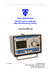
1. Output Terminals
Output current is available on two front panel terminals which are suitable for either wire
compression or 4mm 'wander' plug insertion.
2. Case Terminal
This is connected to the instrument case only and is isolated from the circuitry. The case
provides an electrostatic screen and can be earthed for rejection of noise pick-up.
3. Sensitivity Control
A continuously variable control for adjusting the Null indicator sensitivity. The range of
adjustment is from 25mA (fully anti-clockwise) to 25uA (fully clockwise).
4. Polarity Switch
Normal or reverse polarity is selected by a toggle switch. The centre position is OFF which
provides an open circuit on the output terminals.
5. Voltage Limit Indicator
An LED which indicates when the 1021 is unable to supply sufficient drive voltage to
maintain the set output current, e.g. the maximum drive voltage of the instrument.
6. LED Null Indicator
Used for reading off an unknown current when the instrument is used in the Null mode.
7. Digit Switch
Four-decade thumbwheel switch with 0 to 9 selections on each decade.
8. Source/Null Switch
A two position toggle switch for selecting the mode of operation. In the Source position the
instrument operates as a current source. In the Null position the instrument is used for the
measurement of current.
9. Supply On/Off Switch and Range Switches
Four press button switches with interlocking on the three range switches to ensure that only
one range can be selected at one time.
10. Battery Level Indicator
Located on the top end of the 1021 this continuously monitors the battery voltage. A
minimum mark indicates when the batteries require recharging.
11. Recharge Socket
This is also located on the top end of the instrument. The mains recharger is a separate
unit, the output of which is supplied via a flying lead fitted with a non-reversible plug.
Recharge time is between 12 and 16 hours.
12. V/OP The instrument is overload protected and a front panel indicator shows when
insufficient drive voltage is available (see 5 above). Drive output voltage is adjustable
between 14 volts and 40 volts, with a maximum output power of 2.4 watts.
CAUTION
UNDER NO CIRCUMSTANCES MUST AN ADDITIONAL VOLTAGE BE CONNECTED IN
SERIES WITH THE OUTPUT OF THE 1021 IN AN ATTEMPT TO INCREASE THE
VOLTAGE CAPABILITY AS THIS WILL CAUSE DAMAGE TO THE OUTPUT
CIRCUITRY.
1021 Technical Manual
6