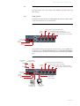
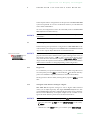
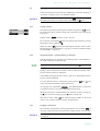
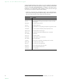
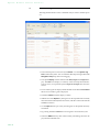
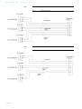
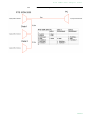
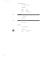
1
ISDN 2005
y
r
a
n
i
m
i
l
e
r
P
Dual ISDN Audio Codec
Hardware/Software Manual
.
RTS
Dual
ISDN
ISDN
2005
Audio
Codec
Hardware/Software
Manual
A publication of:
Telex EVI Audio GmbH
Hirschberger Ring 45
D-94315 Straubing
Phone.:
+49 (0) 9421 706-0
Fax:
+49 (0) 9421 706-378
Internet:
http://www.telex.com
Email:
[email protected]
Printed in Germany, July 2005
© Telex EVI Audio GmbH
All rights reserved. Reproduction in
whole or in parts is prohibited without the
written consent of Telex EVI Audio
GmbH.
Subject to changes.
Release date:
(07.05)
.
CONTENT
INTRODUCTION
SAFETY
9
11
1
CONSTRUCTION
13
2
SYSTEM DESCRIPTION
2.1
Functionality
3
PUTTING THE RTS ISDN 2005 INTO OPERATION 17
3.1
Mounting
3.2
Connection to the mains voltage
3.3
Earthing of the system
3.4
Operational elements on the front side
3.5
Operating modes of the system
4
OPERATION VIA DISPLAY AND KEYPAD
4.1
Basic configurations
4.2
Working with the RTS ISDN 2005
4.3
Comfort Functions 25
5
WINDOWS PC SOFTWARE
5.1
Hardware requirements
5.2
Installing the Windows PC Software
27
6
OPTION: RTS ISDN 2005 KEYPAD
29
6.1
Keypad functions
7
OPTION: REMOTE CONTROL SOFTWARE
7.1
The integrated S0 Monitor 34
A1
MENU STRUCTURE
A1.1
System Settings
A1.2
Operation Settingss 39
A1.3
Presets
A1.4
Status Information
A1.5
Login
A1.6
Names
15
17
43
17
17
18
19
21
21
23
27
27
31
38
40
42
15
41
37
33
A2
RTS ISDN 2005 ADAPTER CABLE 45
A2.1
Keypanel Cable DB9 45
A2.2
Keypanel Cable RJ12 45
A2.3
Matrix Cable DB9 46
A2.4
Matrix Cable RJ12 46
A2.5
Data & Control Adapter Cable 47
A3
TROUBLE SHOOTING 49
A4
INTERFACES 51
A4.1
ISDN and analogue telephone interfaces 52
A4.2
Control and data interfaces 53
A4.3
Audio interfaces 55
A4.4
Headset/Micro Audio interface 56
A4.5
Power supply interface 57
A5
TECHNICAL DATA RTS ISDN 2005
A6
TECHNICAL DATA RTS ISDN 2005 KEYPAD 61
A6.1
Keypad 61
A6.2
LCD Display 62
A6.3
Power supply:
A7
GENERAL 63
A7.1
Ordering numbers
A7.2
Scope of delivery 63
A8
SERVICE INFORMATION 65
INDEX 67
62
63
59
I n t r o d u c t i o n
INTRODUCTION
The system RTS ISDN 2005 is implemented as Dual ISDN Audio Codec and
has analogue and digital AES/EBU Audio interfaces.
The configuration of the system can be carried out via the Windows application included in delivery or via the front keypad of the unit. Optionally, the
RTS ISDN 2005 Keypad is available for separate operation without PC.
English
Deutsch
Menu
Select
System Settings
System Settings
Language
Language
Cap
Ok
Save settings?
Yes
No
Operation Settings
Select
Mode
ISDN
Analogue POTS
Audio
Audio Settings
Audio Settings
Audio input
Audio output
Analogue
Digital
PRETALK Interface
No system
Telephone
Handset
Delete
Opt.
ON AIR
HOLD
PRETALK
Dialling...
Callin
Beendet
Line
Ringing Tone
Search
Names
New Entry
Edit
Display
Delete entry
Save as Quick Dial
Presets
Load
New
PAGE 9
I n t r o d u c t i o n
Save
Delete Preset
Ringing Tone
Signal Processing
Keypad 9600, none
Status information
Login
Shift
PAGE 10
S a f e t y
SAFETY
Introduction
The unit described has been designed to the latest technical paramenters and
complies with all current national and international safety reqirements. It operates on a high level of reliability because of long-term experience in development and constant and strict quality control in our company.
In normal operation the unit is safe.
However, some potential sources of danger for person, material and optimal
operation remain - especially if daily routine and technical errors coincide.
This manual therefore contains basic safety instructions that must be observed during configuration and operation. It is essential that the user reads
this manual before the system is used and that a current version of the manual
is always kept close to the equipment.
General safety requirements
To keep the technically unavoidable residual risk to a minimum, it is absolutely necessary to observe the following rules:
– Transport, storage and operation of the unit must be under the permissible
conditions only.
– Installation, configuration and disassembly must be carried out only by
trained personnel on the basis of the respective manual.
– The unit must be operated by competent and authorised users only.
– The unit must be operated in good working order only.
– Any conversions or alterations to the unit or to parts of the unit (including
software) must be carried out by trained personnel authorised by the manufacturer. Any conversions or alterations carried out by other persons
lead to a complete exemption of liability.
– Only specially qualified personnel is authorised to remove or override
safety measures, and to carry out the maintenance of the system.
– External software is used at one’s one risk. Use of external software can affect the operation of the system.
– Use only tested and virus-free data carriers.
PAGE 11
S i c h e r h e i t
Text Conventions
In this manual the following conventions are used as text markers:
Accentuation: Product names or important terms
LCD Text: Labelling on the front display of the system
PC Text: Labelling in the PC Software
TIP
NOTICE
The symbol TIP marks information which facilitates the operation of the system in its daily use.
The symbol NOTICE marks general notes to observe.
ATTENTION The symbol ATTENTION marks very important advice that is absolutely to
observe. In case of non-observance disfunctions and even system errors are
possible.
!
PAGE 12
C o n s t r u c t i o n
1
CONSTRUCTION
The functions of the RTS ISDN 2005 are implemented in a single unit. The system is designed for mounting in a half 19" rack (1 U).
Optionally, a RTS ISDN 2005 DUAL 19“ Mounting Kit is available for the installation of two RTS ISDN 2005 Systems next to each other.
FIG. 1
FRONT VIEW: RTS ISDN 2005 DUAL ISDN AUDIO CODEC
PAGE 13
C o n s t r u c t i o n
PAGE 14
S y s t e m
2
SYSTEM
D e s c r i p t i o n
DESCRIPTION
The functional elements of the system are pictured in Fig. 2.
FIG. 2
2.1
FUNCTIONAL ELEMENTS RTS ISDN 2005
Functionality
The RTS ISDN 2005 System incorporates an ISDN telephone interface. The
complete signal processing is taken over by two digital signal processors. In
this way the following functions are realised:
DSP1:
– G.711 Audio encoding and decoding
– G.722 Audio encoding and decoding
– Signalising management
– Control of the complete system (Keypad, display, relays, TTL, RS232)
Via the Audio channels 1 & 2 the AUdio signal is inserted or output analogue
or digitally. If the digital AES/EBU Audio interface is used, two separate
Sample Rate Converters are available for automatic clock synchronisation.
For external clocking a clock input and a clock output are available
The configuration and operation can be primarily carried out via the front
keypad and the illuminated display.
Configuration and control is especially comfortable with the RTS ISDN 2005
Windows PC Software which is included in delivery and which communicates with the system via the RS232 interface.
The basic operating functions like accepting a call, dropping a connection and
establsihing a connection with a preprogrammed number can be carried out
via three programmable TTL contacts. Two relays are available for status indication.
PAGE 15
S y s t e m
D e s c r i p t i o n
Optionally, the system can also be operated separately via the RTS ISDN 2005
Keypad that can be connected to the RS232 interface instead of the PC Software.
PAGE 16
P u t t i n g
3
PUTTING
THE
RTS
ISDN
i n t o
2005
o p e r a t i o n
INTO
OPERATION
3.1
Mounting
With its dimensions (W × H × D) of 220 mm × 44,5 mm (1 U) × 220 mm the
RTS ISDN 2005 System can be used either as desktop device or mounted in 19
inch racks. Corresponding 19“ mounting brackets are included in delivery.
Optionally, a mounting kit to install two RTS ISDN 2005 next to each other is
available.
When mounting the unit please keep in mind that the bending radius of the
cables is always greater than the minimum allowed value.
When the RTS ISDN 2005 Audio Codec is installed, please make sure that
there is sufficient ventilation: It is recommended to keep a spacing of ca. 3 cm
from the openings. In general, the ambient temperature of the system should
be within the range of +5° C and +45° C. These thresholds are especially to observe if the system is inserted in a rack. The system works without ventilation.
TIP
The system temperature can be indicated on the display (Menu Status information see CHAPTER A1.4, Page 41))
During operation air humidity must range between 5% and 85%.
ATTENTION Incorrect ambient temperature and humidity can cause functional deficiencies
Operation outside the threshold values indicated above leads to a loss of warranty claim.
!
3.2
Connection to the mains voltage
The system can be operated with mains voltages in the range from 90 V to
253 V via the external power supply included in delivery. The line frequency
can vary from 45 Hz to 65 Hz. The maximum power consumption is 15W. The
rack must be earthed according to the VDE Regulations. The earthing can be
carried out via the earthing screw on the back side of the unit.
The unit does not have a circuit closer and a circuit breaker. After plugging in
the external power supply the system boots within a few seconds. In standby
mode the RTS logo is shown on the display.
3.3
Earthing of the system
For EMC reasons an earthing via the earthing screw of the system must be carried out in either case.
PAGE 17
P u t t i n g
i n t o
o p e r a t i o n
ATTENTION Earthing
A lacking earthing can cause functional deficiencies within the unit.
!
3.4
Operational elements on the front side
The system has an illuminated graphical display with a resolution of 160 x 32
Pixels and 21 operating buttons.
On the right next to the display there are two softkeys whose current functions are indicated on the display. In the middle there are two buttons for navigation (selection upwards/downwards), two buttons for accepting/dropping calls as well as an OK button. The numerical pad supports in addition to
the numerics 0...9 the ’*’ and ’#’ key. For text entries the numerical pad can
also be used as normal keypad.
The operation is similiar to standard mobile telephones.
FIG. 3
OPERATIONAL ELEMENTS ON THE FRONT SIDE
Establish connection
Accept call
Drop/
Main menu
Graphical
display
Softkeys
Navigation
buttons
Keypad for
dialling/ text entry
Confirm
entry/
Status window
PAGE 18
B channel
shift
P u t t i n g
3.5
i n t o
o p e r a t i o n
Operating modes of the system
The figures below show the systems in the different operating modes and
their wirings.
3.5.1
ISDN operation
In the ISDN operating mode two independent B channels are available which
can be used separately for two transmissions.
FIG. 4
MINIMUM WIRING FOR ISDN OPERATION
Analogue Audio 1 (left)/(AES/EBU) Input
Not in
operation
Analogue Audio 2 (right)/(clock) Input
Analogue Audio 1 (left)/(AES/EBU) Output
Analogue Audio 2 (right)/(clock) Output
Power supply
interface
Not in
operation
ISDN
interface
The maximum wiring with all options is shown in Fig. 5. Via the RS232 control interface a PC with RTS ISDN 2005 Software or a RTS ISDN 2005 Keypad
can be connected as alternative to the operation by the front keypad and display.
FIG. 5
Programmable
relays
REL1
Programmable
TTL Inputs/Outputs
Analogue Audio 1 (left)/(AES/EBU) Input
TTL1
TTL2
REL2
MAXIMUM WIRING FOR ISDN OPERATION
TTL3
Not in
operation
Analogue Audio 2 (right)/(clock) Input
Analogue Audio 1 (left)/(AES/EBU) Output
Analogue Audio 2 (right)/(clock) Output
Power supply
interface
Not in
operation
ISDN
interface
2 x transparent
data channels
(RS232 or RS485)
Option:
RTS ISDN 2005
Hybrid Keypad
PC with
RTS ISDN 2005
Software
PAGE 19
P u t t i n g
PAGE 20
i n t o
o p e r a t i o n
O p e r a t i o n
4
OPERATION
VIA
v i a
D i s p l a y
DISPLAY
AND
a n d
K e y p a d
KEYPAD
In this chapter all basic configurations for the operation of the RTS ISDN 2005
system are explained. An overview of the menu structure you will find in the
annex under CHAPTER A1.
Of course, all configurations can also be comfortably made via the RTS ISDN
2005 Software included in delivery.
NOTICE
For the details of most functions please see the PC Software description from
CHAPTER 5.
4.1
Basic configurations
In the following some specific basic configurations of RTS ISDN 2005 are decribed in detail. The configurations for MAGIC DC7 and MAGIC AC1 differ
only in a few aspects. Major differences are marked in the text.
Menu reference number
NOTICE
All menus can be reached directly via a QuickMenu key sequence. For this
purpose each manu item is marked with a cypher in the upper left corner (in
the example on the left it is e. g. 3). To reach a certain menu directly please
enter from the main menu the key sequence Menu <DIGIT> <DIGIT> whereby
<digit> marks the respective menu reference number. Please notice that the
menu reference number can change depending on the configuration.
4.1.1
Keypad lock
To avoid that keys are pressed accidentally you can enable a keypad lock. For
activation please press the Menu key followed by the (star) button. If the keypad lock is enabled the display illumination is turned off immediately.
*
The keypad lock is deactivated by entering the key sequence Menu
time.
4.1.2
* a second
Setting the Audio interface: Analogue or digital
RTS ISDN 2005 incorporates analogue as well as digital Audio interfaces
which you can adjust separately. The digital AES/EBU interfaces have integrated Sample Rate Converters to adjust the digital Audio source to the transmission clock. Additionally, clock inputs/outputs are also available. To configure the Audio interface please follow the instructions below:
NOTICE
If you are not in the main menu please press the
– First press the softkey
Select.
button first.
Menu and select System Settings via the softkey
– With the use of the Select softkey you reach the option Audio Settings.
PAGE 21
O p e r a t i o n
v i a
D i s p l a y
a n d
K e y p a d
– Please mark the option Audio input or Audio output using the cursor keys
and
and press again Select. Now the options Analogue and Digital
are displayed.
– Select the desired interface with the help of the cursor keys
by pressing the softkey Select.
and
and
– Confirm your entry by pressing the Ok button or the softkey Ok.
– To get back to the main menu please press the
button. Now you are
asked if you want to Save settings?. Via the softkey Yes the setting is
stored permanently in the system.
TIP
PAGE 22
You reach the settings for the Audio input or Audio output via the key sequence: Menu 1 1 1 or Menu 1 1 2
O p e r a t i o n
4.2
v i a
D i s p l a y
a n d
K e y p a d
Working with the RTS ISDN 2005
In the next chapters basic functions like establishing a connection, dropping a
connection, accepting calls etc. are decribed in detail.
NOTICE
If you are not in the main menu please press the
button first.
From the main menu you reach the status window via the Ok button.
4.2.1
Calling a partner
From the main menu just enter the phone number using the keys 0...9. The input field for the phone number is displayed automatically after entering the
first cypher.
With the softkey Delete misentries can be corrected.
The connection is established after the entry of the phone number by pressing
the telephone receiver button .
Under the softkey Opt. (Options) the entered phone number can be saved in
the phone book see CHAPTER 4.3.1, Page 25) or stored as QuickDial number
see CHAPTER 4.3.2, Page 25).
4.2.2
The Status Display - Operation during a connection
After the telephone receiver button is pressed the partner is called and the status window is displayed automatically.
TIP
The status window can always be reached by pressing the OK button.
During a stereo connection the number of the connected B channels is displayed to the left of the level indication.
In the ISDN operating mode the window is split if two independent connections have been established.
To switch between the two connections, please press the Shift key (#). The
name of the selected channel is displayed inversely.
An outgoing call is signalised by Dialling... . The dialled number (or the name
if a phone book entry is selected) is displayed in the first line.
When the connection is established the level indication for the incoming signal(Receive) and for the outgoing signal(Transmit) is displayed.
With the use of the softkey Opt. the displayed phone number can be stored
and it is also possible to directly switch to the phone book.
4.2.3
Dropping a connection
The connection is dropped by pressing the telephone receiver button
. If
no further connection exists, the main menu is displayed after a few seconds.
NOTICE
Please make sure that you have selected the right channel if you want to drop
a connection.
PAGE 23
O p e r a t i o n
v i a
D i s p l a y
a n d
4.2.4
K e y p a d
Accepting a call
If the RTS ISDN 2005 receives a call, it is automatically signalised in the status
window by Callin.
NOTICE
Additionally, a system ringing tone can be enabled.
The call can be directly accepted with the telephone receiver button
.
If you want to reject the call, please press the following telephone receiver
button
.
PAGE 24
O p e r a t i o n
4.3
Comfort Functions
4.3.1
Redialling
v i a
D i s p l a y
a n d
K e y p a d
You reach the redialling function by pressing again the telephone receiver
button
for the line on which no connection currently exists. The recently
called partners are displayed in a list. In the input field Search you can search
for a certain partner or select a partner from the list using the cursor keys
and
.
To call a partner please press again the telephone receiver button
.
NOTICE
To enter characters you can use the alphanumeric keypad. You reach the desired character by pressing the respective key several times. To type e.g. a ’K’
you need to press the button ’5’ twice. Misentries can be corrected with the
help of the softkey Delete.
To switch between upper and lower case please press the SHIFT key. The display changes from ABC to abc.
4.3.2
Using the phone book
The system incorporates a comfortable phone book function. You reach the
phone book from the main menu via the softkey Names.
In the input field Search you can search for a certain partner. As soon as you
enter a character the corresponding phone book entries are filtered out.
Alternatively, you can select a partner from the list using the cursor keys
and
.
By the softkey Opt. (Options) the following functions, which you can select via
the softkey Select, are realised:
– New Entry: With the help of this function you create a new phone book
entry.
First enter the name and confirm your entry with Ok.
Then enter the phone number of the partner and confirm it as well with Ok.
– Edit: This function allows you to edit already existing phone book entries.
– Display: The selected phone book entry is displayed with name and phone
number.
– Delete entry: The selected phone book entry is deleted. For safety reasons
you are asked if you really want to delete the entry.
– Save as Quick Dial: Your 10 most important phone numbers can be programmed as Quick Dialling numbers on the numerical keys ’0’ ... ’9’.
Please select the key from the list on which you want to programme the
phone number.
PAGE 25
O p e r a t i o n
v i a
D i s p l a y
a n d
K e y p a d
To activate a Quick Dialling number just press from the main menu the
desired Quick Dial key for at least 3 seconds. The connection to the partner
is established automatically.
TIP
4.3.3
The phone book functions can also be reached directly via the QuickBook
function. Please press the following key sequence: Names Opt. <DIGIT>
Example: Save as Quick Dial - Names Opt. 5
Working with Presets
The RTS ISDN 2005 differentiates between System Settings and Operation
Settings.
System Settings are settings that do not change during normal operation like
e.g. language, date/time etc. These parameters cannot be saved as Preset
since a configuration is usually only required when the system is put into operation.
Operation Settings like e.g. the line interface ISDN or Analogue POTS, Ringing Tone, etc, need to be reconfigured depending on the application. To easily
recall recurring configurations you can store up to 10 Presets in the system.
You reach the menu for the Presets by pressing the Menu softkey once, the cursor key
twice and by pressing the softkey Select once as confirmation.
In the input field Presets you can search for a certain Preset. As soon as you
enter a character, the corresponding entries of the Preset list are filtered out.
Alternatively, you can select a Preset from the list using the cursor keys
and
.
If you now press the Ok button, the selected Preset is loaded immediately.
By the softkey Opt. (Options) the following functions which you can select via
the softkey Select are realised:
– Load: The stored Preset is loaded.
– New: With the help of this function you can create a new Preset. All current
Operation Settings are stored.
– Save: The currently selected Preset is overwritten with the current Operation Settings. For safety reasons a confirmation is required.
– Delete Preset: The currently selected Preset is deleted. For safety reasons
a confirmation is required.
NOTICE
PAGE 26
If the configuration has changed, you are asked if you want to Save settings?
when you leave the Preset menu. Via the Yes softkey the configuration is
stored permanently in the system. This Preset is loaded automatically by the
system after the unit is connected to the power supply.
W i n d o w s
5
WINDOWS
PC
P C
S o f t w a r e
SOFTWARE
The configuration of the system is particularly comfortable via the Windows
PC Software included in delivery.
5.1
Hardware requirements
The PC must meet the following minimum requirements:
– IBM PC AT, IBM PS/2 or 100% compatible
– Pentium Prozessor (> 500 MHz) recommended
– Windows 2000/XP
– ca. 600 kByte available RAM
– 5 MB available hard disk space
– Screen resolution with 800 x 600 Pixels
– at least one available serial interface RS-232
– Microsoft, IBM PS/2 or 100% software compatible mouse
5.2
Installing the Windows PC Software
Please insert the CD included in delivery in your CD-ROM drive. The software automatically starts your Internet browser. Possible safety warnings can
be ignored for the moment. Please press under Install Software the RTS
ISDN 2005 button. Subsequently, the setup program is executed.
Alternatively, you can install the software directly from the CD. You will find
the installation file setup.exe in the folder Software\RTS ISDN 2005 on the
CD.
Please follow the instructions of the installation routine.
After the installation the software can be started by clicking on the RTS ISDN
2005.
Please connect your PC via a serial 1:1 cable (only Pin 2 and Pin 3 are used, Pin
5=ground) with the system.
The standard COM-Port settings are: PC (19200 Baud)
Operation via Windows PC software
In the following chapters all functions of the PC software are described in detail.
PAGE 27
W i n d o w s
PAGE 28
P C
S o f t w a r e
O p t i o n :
6
OPTION:
RTS
ISDN
R T S
2005
I S D N
2 0 0 5
K e y p a d
KEYPAD
The optional RTS ISDN 2005 Keypad ensures a comfortable and simple operation of the system for users who do not want to use the front keypad and display and who do not want use a PC to operate the hybrid.
NOTICE
To use the Keypad with the RTS ISDN 2005 you must adjust the interface parameters of the RS232 interface to 9600 Baud, no parity. Via the Quick Menu
function you reach the settings for the R232 parameters directly by the key sequence Menu 1 4 . Please select Keypad 9600, none.
The following figure shows the operational elements of the Keypad.
FIG. 6
KEYPAD ASSIGNMENT OF THE RTS ISDN 2005 KEYPAD
Please connect the 9 pole SUB-D connector of the RTS ISDN 2005 Keypad with
the RS232 interface see CHAPTER A4.2, Page 53) of the RTS ISDN 2005 System. Since the RTS ISDN 2005 Keypad needs its own power supply please
PAGE 29
O p t i o n :
R T S
I S D N
2 0 0 5
K e y p a d
connect the 230V external power supply to a power socket and connect the 6
pole Mini-DIN socket of the external power supply with the 6 pole Mini-DIN
connector of the RTS ISDN 2005 Keypad. If everything is connected correctly,
the display is now illuminated. After switching on 1 the system, the message
you can see in our figures is displayed after booting.
– If there is a connection error, the ISDN provides various alarm messages..
Please see the following table for their meanings. The LCD display shows
the relevant B channel first followed by the alarm message.
TAB. 1
Alarm message
Description
Unass. number
The number is not recognised by the ISDN. Please check your entry
No route
No route. When this message appears the ISDN is normally overloaded.
Please dial again.
Normal disc.
The connection has been cleared.
User busy
The number called is busy.
No user resp.
The called number is not responding. Possibly the wrong number was dialled.
Call rejected
The call was rejected. Possibly the partner has rejected your call.
Number chang.
The dialled number has been changed.
Destin. error
The called end is not operational. Maybe the unit is switched off.
Inval. number
Invalid number.
No line avai.
No B channel available.
No Network
No ISDN available. Check your ISDN line.
Netw. failure
Temporary ISDN failure.
Congestion
ISDN network error. Maybe the wrong ISDN protocol is selected.
Bearer capab.
The wanted service is not available.
Bearer serv.
The wanted service is not implemented.
Remote disc.
Connection has been dropped by the partner
Procedure er.
Remote or local ISDN procedure error.
Cannot dial
System cannot dial.
1
PAGE 30
ISDN ALARM MESSAGES
If the system has already been switched on, please press the button „C“ or „AC“ once.
O p t i o n :
6.1
R T S
I S D N
2 0 0 5
K e y p a d
Keypad functions
Below you will find the keypad functions listed in table form.
PAGE 31
O p t i o n :
PAGE 32
R T S
I S D N
2 0 0 5
K e y p a d
O p t i o n :
7
OPTION:
REMOTE
R e m o t e
C o n t r o l
CONTROL
S o f t w a r e
SOFTWARE
The fee-based RTS ISDN 2005 Remote Control & ISDN Monitor Plug-In Software enables you to access the RTS ISDN 2005 System from any PC with an
integrated ISDN card. A local RTS ISDN 2005 System is not required. The
software option is protected by an USB Dongle. A special highlight is the integrated ISDN S0 Monitor which allows a detailed analysis of the D channellocally as well as remotely.
PAGE 33
O p t i o n :
R e m o t e
C o n t r o l
7.1
S o f t w a r e
The integrated S0 Monitor
The integrated S0 Monitor allows a detailed analysis of the D channel protocol.
FIG. 7
S0 MONITOR USER
• The D channel protocol can be analysed Online or via the System Log
File stored in the system. You can select the desired operating mode under
Navigation. Stop stops the current logging.
• The option Display switches between the User, Layer 2 and Layer 3 display. The User view displays a summary of the most important information. Of course, for experts the options Layer 2 and Layer 3 are also informative.
• Errors in the log file are displayed red-shaded. Via the button Go to Error
the next error in the log file is displayed.
• The button Reset resets the display window.
• With the use of the Export key the log file can be exported in the currently
selected readout as RTF (Rich Text Format). This file can be read with MS
WORD for instance.
• Via the Open button a previously stored log file can be opened and analysed offline.
• By pressing the button Save the current log file is stored as binary file.
• In the line HEX the binary data of the currently selected log file line is displayed in hexadecimal form.
PAGE 34
O p t i o n :
R e m o t e
C o n t r o l
S o f t w a r e
• Using Filter you can filter the log file for certain criteria. S0 selects the
ISDN interface of the system. For the RTS ISDN 2005 this value must always be „0“ respectively be empty since the system incorporates only one
ISDN interface.
Using the filter CR (Call Reference) you can display all available entries for
a transaction. Additionally, the colour in which the entries are displayed
is changed for each new Call Reference.
FIG. 8
S0 MONITOR LAYER 2
PAGE 35
O p t i o n :
R e m o t e
C o n t r o l
S o f t w a r e
FIG. 9
PAGE 36
S0 MONITOR LAYER 3
M e n u
A1
MENU
S t r u c t u r e
STRUCTURE
On the following pages you will find the complete menu structure if you select ENGLISH as menu language
From the main menu you reach the phone book directly via the softkey Names.
With the use of the softkey Menu you get to the configuration of the system.
The configuration menu is divided in five submenus:
– System Settings
– Operation Settings
– Presets
– Status information
– Login
NOTICE
Please note that depending on the selected operating mode some menu items
are not displayed.
If you use an Administrator and/or User Password, the display looks as it is
described below:
(1)
Only Administrator Password configured: The password must be enetered for changes to the basic settings and operation settings only. Immediately available menus:
– Presets
– Status information
– Login
(2)
Only User Password configured (instead of Menu, Login is displayed):
The password must always be entered. Subsequently, all menus are
available.
(3)
User and Administrator Password configured (instead of Menu Login is
displayed):
– User Password is entered: The menus Presets, Status information
and Login are available
– Administrator Password is entered: Alle menus are available.
NOTICE
There is no differentiation between upper and lower case for the password
entry.
PAGE 37
M e n u
S t r u c t u r e
A1.1
PAGE 38
System Settings
M e n u
A1.2
S t r u c t u r e
Operation Settingss
PAGE 39
M e n u
S t r u c t u r e
A1.3
PAGE 40
Presets
M e n u
A1.4
S t r u c t u r e
Status Information
PAGE 41
M e n u
S t r u c t u r e
A1.5
PAGE 42
Login
M e n u
A1.6
S t r u c t u r e
Names
PAGE 43
M e n u
PAGE 44
S t r u c t u r e
R T S
A2
RTS
A2.1
Keypanel Cable DB9
FIG. 10
A2.2
ISDN
2005
I S D N
2 0 0 5
ADAPTER
A d a p t e r
C a b l e
CABLE
KEYPANEL CABLE DB9
Keypanel Cable RJ12
FIG. 11
KEYPANEL CABLE RJ12
PAGE 45
R T S
I S D N
2 0 0 5
A d a p t e r
A2.3
C a b l e
Matrix Cable DB9
FIG. 12
A2.4
Matrix Cable RJ12
FIG. 13
PAGE 46
MATRIX CABLE DB9
MATRIX CABLE RJ12
R T S
A2.5
I S D N
2 0 0 5
A d a p t e r
C a b l e
Data & Control Adapter Cable
PAGE 47
R T S
I S D N
PAGE 48
2 0 0 5
A d a p t e r
C a b l e
T r o u b l e
A3
TROUBLE
TAB. 2
S h o o t i n g
SHOOTING
TROUBLE SHOOTING
Problem
Possible cause
The Echo Canceller is not working.
If you switch callers via a Call-In Center to the hybrid the Echo
Canceller is possibly adjusted incorrectly. Enable the Echo
Canceller permanently (see ???). Please notice that echoes of
more than 32 ms cannot be filtered out anymore.
PAGE 49
E r r o r
PAGE 50
C o r r e c t i o n
I n t e r f a c e s
A4
INTERFACES
The interfaces of the system are pictured in Fig. 14.
FIG. 14
REAR VIEW OF THE RTS ISDN 2005 AUDIO CODEC
NOT IN OPERATION
All interfaces are described below.
PAGE 51
I n t e r f a c e s
A4.1
ISDN and analogue telephone interfaces
A4.1.1
S0 interface
This interface supports two B channels in ISDN lines with EURO ISDN (DSS1) protocol.
1
8
TAB. 3
PIN ASSIGNMENT: S0 INTERFACE (LINE ISDN)
Socket: Western (8-pole) RJ45
A4.1.2
Pin
Signal
Electrical characteristics
1
not used
2
not used
Recommendation:
Data rate:
3
TX a
Data out a
4
RX a
Data in a
5
RX b
Data in b
6
TX b
Data out b
7
not used
8
not used
POTS 1 interface
Not in operation.
1
PAGE 52
POTS = Plain Old Telephone Service
I.430
B channel: 2x64 kbit/s
D channel: 16 kbit/s
I n t e r f a c e s
A4.2
Control and data interfaces
A4.2.1
CTRL/DATA interface
The CTRL/DATA interface is used for the configuration and operation of the
RTS ISDN 2005 System via a PC. To connect a PC you need a 1:1 connecting
cable in which Pin 2 and Pin 3 are not crossed. Furthermore, Pin 5 GND must
be connected.
Additionally, two further data interfaces for transparent data transmission
are implemented by this interface. The two interfaces can be independently
configured by software either as RS485 or as RS232 interface.
NOTICE
Please note that the function of the Pins RXD1 and TXD1 - input or output is determined by the interface type DCE or DTE. The pin assignment for Pin
2 is always RXD and for Pin 3 it is always TXD.
For both data interfaces RXD serves as receive path and TXD serves as transmit path.
5
9
1
6
TAB. 4
PIN ASSIGNMENT: CTRL/DATA INTERFACE
Socket: SUB-D, 9-pole
Pin
Signal
1
2
Electrical characteristics
not used
PC interface RS232:
PC RS232 Receive Data
Type (Pin 2, 3):
Level:
Data rate:
Range:
Protocol:
2
RXD1
3
TXD1 3
PC RS232 Transmit Data
4
RXD3
Data RS232 (input)/RS485 (b)
5
GND
Earth
6
TXD3
Data RS232 (output)/RS485 (a)
Data interfaces:
7
RXD2
Data RS232 (input)/RS485 (b)
Level:
8
TXD2
Data RS232 (input)/RS485 (a)
Data rate:
Range:
9
not used
Protocol:
DCE 1
V.24
38400 Baud
max. 15 m
1 start bit
8 data bits
1 stop bit
V.24 (RS232)
V.11 (RS485)
38400 Baud
max 15m (RS232)
max. 100 m (RS485)
1 start bit
8 data bits
1/2 stop bit
Parity adjustable
1
DCE = Data Communication Equipment: to connect a PC a 1:1 cable is required
2
ATTENTION: on this Pin the RTS ISDN 2005 transmits data
3
ATTENTION: on this Pin the RTS ISDN 2005 receives data
PAGE 53
I n t e r f a c e s
A4.2.2
TTL/RELAY interface
Via this interface external control signals can be used.
5
9
PAGE 54
1
6
TAB. 5
PIN ASSIGNMENT: TTL/RELAY INTERFACE (TTL/RELAY)
Socket: SUB-D, 9-pole
Pin
Signal
1
+5V/300mA output
2
TTL 1 IN/OUT
3
TTL 2 IN/OUT
4
TTL 3 IN/OUT
5
GND
6
Relay 1a
7
Relay 1b
8
Relay 2a
9
Relay 2b
Elektrical characteristics
Capacity of the TTL outputs:
Maximum voltage: 5V
Maximum current: 10mA
Capacity of the relays:
Maximum voltage: 48V
Maximum current: 200mA
I n t e r f a c e s
A4.3
Audio interfaces
The system incorporates analogue and digital AES/EBU Audio interfaces.
For switching you can use display and keypad or the PC software.
A4.3.1
TAB. 6
Push
2
Analogue Audio interface
1
3
PIN ASSIGNMENT: ANALOGUE INPUT (AUDIO 1/2 IN)
Socket: 3-pole XLR
Pin
Signal
Elektrical characteristics
1
GND
Input level:
adjustable -3 .... +9 dBu
2
AUDIO IN a
Impedance:
> 25 kΩ
3
AUDIO IN b
Head room: 6 dB
TAB. 7
2
1
3
A4.3.2
PIN ASSIGNMENT: ANALOGUE OUTPUT (AUDIO 1/2 OUT)
Connector: 3-pole XLR
Pin
Signal
Elektrical characteristics
1
GND
Output level:
adjustable -3 .... +9 dBu
2
AUDIO OUT a
Impedance:
< 50 Ω
3
AUDIO OUT b
Head room: 6 dB
Digital AES/EBU Audio interface
The RTS ISDN 2005 System incorporates two digital inputs/outputs which
are physically one AES/EBU interface. The input as well as the output has its
own sample rate converter providing that a digital source with 32, 44.1 or 48kHz can be connected directly. For external clocking (48-kHz only) the word
clock input or output may be used.
TAB. 8
Push
2
1
3
PIN ASSIGNMENT: DIGITAL INPUT (AES IN)
Socket: 3-pole XLR
Pin
Signal
Electrical characteristics
1
GND
IEC-958
2
AUDIO IN a
3
AUDIO IN b
TAB. 9
2
1
3
PIN ASSIGNMENT: DIGITAL OUTPUT (AES OUT)
Connector: 3-pole XLR
Pin
Signal
Elektrical characteristics
1
GND
IEC-958
2
AUDIO OUT a
3
AUDIO OUT b
PAGE 55
I n t e r f a c e s
TAB. 10
Push
2
1
3
PIN ASSIGNMENT: CLOCK INPUT (CLK IN)
Socket: 3-pole XLR
Pin
Signal
Elektrical characteristics
1
GND
TTL
2
CLOCK IN
3
not used
TAB. 11
2
1
3
A4.4
PIN ASSIGNMENT: CLOCK OUTPUT (CLK OUT)
Connector: 3-pole XLR
Pin
Signal
Electrical characteristics
1
GND
TTL
2
CLOCK OUT
3
not used
Headset/Micro Audio interface
Not in operation.
PAGE 56
I n t e r f a c e s
A4.5
Power supply interface
The power supply is connected via an external power supply.
TAB. 12
3
1
2
PIN ASSIGNMENT: POWER SUPPLY
Socket: KYCO KPJ-S3
Pin
Signal
Elektrical characteristics
1
GND
Voltage:
+12V
2
+12V
Power:
max. 15W
3
not used
PAGE 57
I n t e r f a c e s
PAGE 58
T e c h n i c a l
A5
TECHNICAL
DATA
RTS
ISDN
D a t a
2005
PAGE 59
PAGE 60
T e c h n i c a l
A6
TECHNICAL
DATA
RTS
ISDN
D a t a
2005
KEYPAD
A6.1
Keypad
Matrix:
8x6
32 keys
(4 quad keys, 4 double keys, 24singlekeys)
FIG. 15
CONNECTING CABLE MAGIC SYSTEM - KEYPAD
to power supply
(1)
(2)
(3)
to Keypad
to RTS ISDN 2005
Protocol:
9600 Baud
no parity
Connection to external power supply (1):
6-pole Mini-DIN connector
Assignment:
6
5
3
4
1
Pin 3:
Pin 4:
2
GND (ground)
+5V
Connection to RTS ISDN 2005 (2):
9-pole SUB-D connector
1
6
5
Assignment:
9
Pin 2
Pin 3
Pin 5
RXD
TXD
GND (ground)
PAGE 61
T e c h n i c a l
D a t a
Connection to Keypad (3):
8-pol. MINI DIN connector
Assignment:
Pin 2:
Pin 3:
Pin 4:
Pin 5:
A6.2
clock
+5V
data
GND (ground)
LCD Display
2 x 20 characters
illuminated
A6.3
Power supply:
5V, max. 500 mA
Connection:
6-pole Mini-DIN socket
6
5
4
3
2
PAGE 62
1
Assignment:
Pin 3:
Pin 4:
GND (ground)
+5V
G e n e r a l
A7
GENERAL
A7.1
Ordering numbers
RTS ISDN 2005 System
800241
Windows PC Software Update
XXXXX 1
Accessories
RTS ISDN 2005 Keypad
800240
RTS ISDN 2005 DUAL 19“ Mounting Kit
800242
Software Options
RTS ISDN 2005 Remote & ISDN Monitor Plug-In 2
A7.2
430231
Scope of delivery
– RTS ISDN 2005
– CD Windows PC Software
– External power supply
Input:
100 - 240V/24W, 50 - 60 Hz
Output:
12V
– Self adhesive feet
– 19’’ Mounting Brackets
– Manual
– 1 x S0 cable
1
also available in the internet under this identity number
2
An ISDN PC card and at least one USB interface are required for the Software Dongle
PAGE 63
G e n e r a l
PAGE 64
S e r v i c e
A8
SERVICE
I n f o r m a t i o n
INFORMATION
PAGE 65
S e r v i c e
PAGE 66
I n f o r m a t i o n
I n d e x
INDEX
Numerics
1 U 13
19 " 17
19" rack 13
19-inch-rack 17
230V external power supply 30
9-pole SUB-D connector 29
A
ABC 25
Accepting/dropping calls 18
Accessories 63
Administrator 37
AES/EBU 21, 55
Air humidity 17
Ambient temperature 17
Analogue 21, 22
Audio input 22
Audio interface 21
Audio output 22
Audio settings 21
B
B channel 52
Basic configurations 21
C
Call Reference 35
Callin 24
Calling 23
Channel shifting 23
COM-Port 27
Configuration 27, 37
Connecting cable 53
Conventions 12
CR 35
Cursor keys 25
D
D channel protocols 34
Date/Time 26
Deactivation 21
Delete 23, 25
Delete entry 25
Delete Preset 26
Desktop device 17
Digital 21, 22
Display 18, 25, 55
Display illumination 21
Dongle 63
Dropping 23
DSS-1 52
DTE 53
Dual Mounting Kit 13
E
Earthing 17
Earthing screw 17
Edit 25
EMC 17
English 37
EURO ISDN 52
External power supply 57
F
Front view 13
Functional elements 15
H
Hardware requirements 27
Headroom 17, 55
HEX 34
I
Input field 23
Install Software 27
Installation 27
Interface 51
ISDN 19, 23, 52
ISDN operating mode 19
K
Keypad 55
L
Language 26
LCD display 30, 62
PAGE 67
I n d e x
Level indication 23
Line frequency 17
Load 26
Login 37
M
Main menu 21, 23, 37
Mains voltage 17
Menu 37
Menu structure 21, 37
Minimum requirements 27
Mounting brackets 17
N
Names 25, 37
Navigation 18, 34
New 26
New entry 25
Numerical keys 25
O
Online 34
Operating buttons 18
Operating mode 19
Operation 11
Operation settings 37
Operational elements 18
Ordering numbers 63
P
Password 37
PC 53
PC Software 55
Phone book 23, 25, 37
Phone book entry 25
Phone number 23
POTS 52
POTS interface 52
Power consumption 17
Power supply 62
Preset 26
Preset menu 26
Presets 26, 37
Putting the system into operation 26
Q
QuickBook 26
QuickDial 25, 26
QuickDial number 23
QuickMenu 21
P A GE 6 8
R
Rack 17
Receive 23
Redialling 25
Relay 54
Resolution 18
Rich Text Format 34
RS232 19
RTF 34
RTS ISDN 2005 DUAL 19"
Mounting Kit 13
RTS ISDN 2005 Keypad 19, 29
RTS ISDN 2005 Software 19, 21
S
S0 35
S0 interface 52
Safety instructions 11
Sample Rate Converter 21, 55
Save 26
Save as Quick Dial 25
Scope of delivery 63
Search 25
Serial cable 27
Setup 27
SHIFT 23, 25
Softkey 18
Software 21
Standby mode 17
Status information 37
Status window 23
Storage 11
System settings 21, 37
System temperature 17
T
Telephone receiver button 25
Threshold values 17
Transmission clock 21
Transmit 23
Transport 11
TTL 54
U
USB 63
User 37
User busy 30
V
Ventilation 17
I n d e x
W
Warranty claim 17
Wiring 19
PAGE 69
I n d e x
P A GE 7 0