1
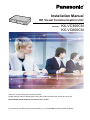
Installation Manual
HD Visual Communication Unit
Model No.
KX-VC300CN
KX-VC600CN
Thank you for purchasing this Panasonic product.
Please read this manual carefully before using this product and save this manual for future use.
KX-VC300/KX-VC600: Software File Version 3.01 or later
In this manual, the suffix of each model number (e.g., KX-VC600CN) is omitted unless necessary.
Introduction
Introduction
Feature Highlights
Simple Installation
If you have a network connection and an HDMI-compatible display, you can simply connect these, along with
the Boundary Microphone (proprietary cable included) and video camera, to the unit using 2 HDMI cables and
1 LAN cable.
Lifelike Visual Communication
You can experience lifelike visual communication*1 with smooth, high-quality video and clear stereo*2 sound.
*1
*2
If you are using the KX-VC300, sending images in Full HD can only be done by purchasing an activation key card (KX-VCS401) to
activate this feature.
If using 2 or more Digital Boundary Microphones, stereo output can be enabled through system settings. For details, refer to the User
Manual. When using Digital Boundary Microphones and an Analogue Boundary Microphone together, stereo output may be
unavailable depending on the connection configuration (Page 21, Page 23).
Home Electronics-style Remote Control Operation and Simple, Easy to
Understand Graphical User Interface
You can make settings and perform operations using familiar remote control operations and a simple, easy to
understand interface.
Stabilised Communication Quality
In periods of network congestion, automatic packet transmission rate quality control prevents packet loss to
maintain a video conference call’s image and sound quality. This allows visual communication with stabilised
communication quality even over an intranet connection.
Remote Video Camera Operation via Remote Control
You can move your own video camera up, down, left, and right as well as zoom in and out. You can also register
up to 9 preset patterns of video camera direction and zoom level which allows you to easily change the video
camera’s direction and zoom level by selecting a preset. Additionally, you can also use your remote control to
control the other party’s video camera.*1 For details, refer to the User Manual.
*1
To be able to control another party’s video camera, settings must be configured on the other party’s unit. For details, refer to the User
Manual.
Selectable Video Source
By connecting your computer or video camera to the unit, you can show your computer’s screen or video
camera image to video conference call participants.
Making Video Conference Calls via SIP Server
By using a SIP server, you can establish video conference calls not just by IP address, but also by specifying
a SIP URI (SIP user name@SIP domain name) instead. If the other party uses the same SIP domain name
2
Installation Manual
Introduction
as you, you can make a video conference call by specifying only the SIP user name.*1 For information about
supported SIP servers, contact your dealer.
*1
To make a video conference call using a SIP URI or SIP user name, you must first configure SIP settings. For details about SIP
settings, refer to the User Manual.
Enhanced Features through the Use of Activation Keys
By using an activation key (sold separately), you can upgrade the features of the KX-VC300 (Page 14). After
you upgrade the features, the KX-VC300 can initiate 3-party/4-party video conference calls and send images
in Full HD resolution. Features enabled through activation keys are available even after performing a system
initialisation.
Connection to non-Panasonic Video Conference Systems
You can connect to a non-Panasonic video conference system and have a 2-party video conference call.*1
*1
For details about the types of non-Panasonic video conference systems you can connect to, contact your dealer.
MCU Connection
By connecting to an MCU (multipoint control unit), you can make multiple-party video conference calls with 5
or more parties, rather than the normal maximum of 4 parties.*1
*1
For details about the types of MCUs you can connect to, contact your dealer.
Installation Manual
3
Introduction
Notations
•
•
•
Windows® refers to the Microsoft® Windows operating system.
Windows XP refers to the Microsoft Windows XP operating system.
Windows 7 refers to the Microsoft Windows 7 operating system.
Trademarks
•
•
•
•
Microsoft, Windows, and Internet Explorer are either registered trademarks or trademarks of Microsoft
Corporation in the United States and/or other countries.
HDMI is a trademark or registered trademark of HDMI Licensing LLC in the United States and other
countries.
Polycom® is a trademark owned by Polycom, Inc. in the US and other countries.
All other trademarks identified herein are the property of their respective owners.
Licences
•
•
•
This product is licensed under the AVC Patent Portfolio License. This license permits the end user to
perform, for personal and non-commercial use, only the following actions:
– Encode video in compliance with the AVC Standard (below, "AVC Video").
– Decode AVC Video that was encoded by a consumer engaged in both personal and non-commercial
activity.
– Decode AVC Video obtained from a video provider licensed to provide AVC Video.
Additional information may be obtained from MPEG LA, LLC. See http://www.mpegla.com.
This product incorporates G.722.1 and G.722.1 Annex C licensed by Polycom®.
This product incorporates Qt library licenced by Digia Plc. Please read "EULA" of system settings of this
product.
Open Source Software
Parts of this product use Open Source Software supplied based on the conditions of the Free Software
Foundation’s GPLs and/or LGPLs and other conditions. Relevant conditions apply to this software. Therefore,
please read license information about GPLs and LGPLs, and "License Info." of system settings of this product
before using this product. Also, some software parts of this product are licensed under the MOZILLA PUBLIC
LICENSE (MPL). At least three (3) years from delivery of products, Panasonic will give to any third party who
contacts us at the contact information provided below, for a charge of no more than the cost of physically
distributing source code, a complete machine-readable copy of the corresponding source code and the
copyright notices covered under GPL, LGPL, and MPL. Please note that software licensed under GPL, LGPL,
and MPL is not under warranty.
Contact Information
http://www.panasonic.net/corporate/global_network/
4
Installation Manual
Introduction
Miscellaneous
About the Screen Shots and Illustrations in this Manual
The screen shots, illustrations and descriptions in this manual are based on using the KX-VC600. If you are
using the KX-VC300, please note that some displayed features will not be available for your model.
Copyright
The software used in this product uses source code from Radvision Ltd.
Portions of this software are © 1996-2012 RADVISION Ltd. All intellectual property rights in such portions of
the Software and documentation are owned by RADVISION and are protected by United States copyright laws,
other applicable copyright laws and international treaty provisions. RADVISION and its suppliers retain all rights
not expressly granted.
Installation Manual
5
Table of Contents
Table of Contents
1 For Your Safety ........................................................................................7
2 Before Operation ....................................................................................11
2.1
2.2
2.3
Notes about Operation ...................................................................................................11
Data Security ...................................................................................................................12
Privacy and Right of Publicity .......................................................................................12
3 Included and Optional Accessories .....................................................13
3.1
3.2
Accessory Information ...................................................................................................13
Optional Accessories .....................................................................................................14
4 Part Names and Usage ..........................................................................15
4.1
4.2
4.3
Main Unit (Front) .............................................................................................................15
Main Unit (Back) ..............................................................................................................16
Remote Control ...............................................................................................................17
5 Connection and Preparation .................................................................19
5.1
5.2
5.3
5.4
Device and Network Connection ...................................................................................19
Connecting the Unit ........................................................................................................20
Preparing the Unit ...........................................................................................................26
Preparing Remote Control .............................................................................................27
6 Settings and Confirmation ....................................................................28
6.1
6.2
6.3
6.4
6.5
6.5.1
6.5.2
6.5.3
6.5.4
6.6
6.6.1
6.6.2
Inputting Letters and Numbers ......................................................................................28
Initial Settings ..................................................................................................................32
Displaying the Connection Status .................................................................................34
Software Update with a USB Memory Device ...............................................................35
System Settings ..............................................................................................................37
How to Perform System Settings Using a Computer .....................................................37
Changing the Settings ....................................................................................................38
Adding to the Contact List ..............................................................................................41
Entering the Device Name .............................................................................................42
Remote Access Settings ................................................................................................43
Updating Software ..........................................................................................................43
Updating the Contact List ...............................................................................................44
7 After Installation .....................................................................................45
7.1
7.2
Confirming the Settings and Connection .....................................................................45
Adjusting Conditions in Call Environment ...................................................................48
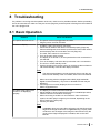
8 Troubleshooting .....................................................................................49
8.1
8.2
8.3
8.4
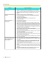
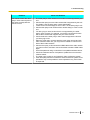
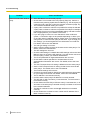
Basic Operation ...............................................................................................................49
Audio ................................................................................................................................54
System Settings ..............................................................................................................56
If These Messages Appear .............................................................................................57
9 Specifications .........................................................................................58
Index..............................................................................................................62
6
Installation Manual
1 For Your Safety
1 For Your Safety
To prevent personal injury and/or damage to property,
be sure to observe the following safety precautions.
WARNING
General
Follow all warnings and instructions
marked on the unit.
The following symbols classify and describe the
level of hazard and injury caused when this unit is
operated or handled improperly.
WARNING
Denotes a potential hazard that could result in
serious injury or death.
CAUTION
Denotes a hazard that could result in minor injury or
damage to the unit or other equipment.
The following types of symbols are used to classify
and describe the type of instructions to be
observed. (The following symbols are examples.)
This symbol is used to alert users to a specific
operating procedure that must not be performed.
This symbol is used to alert users to a specific
operating procedure that must be followed in order
to operate the unit safely.
Power
The power source voltage of this unit is
listed on the nameplate. Only plug the
unit into an AC outlet with the proper
voltage. If you use a cord with an
unspecified current rating, the unit or
plug may emit smoke or become hot to
the touch.
Do not connect the unit to the AC outlet,
AC extension cords, etc., in a way that
exceeds the power rating of, or does not
comply with the instructions provided
with, the AC outlet, AC extension cords,
etc.
Connect the AC adaptor firmly to the
power cord, and plug the power cord
firmly into an AC outlet. Otherwise, it can
cause fire or electric shock.
Do not pull, bend, rest objects on, or
chafe the power cord, plug, and AC
adaptor. Damage to the power cord or
plug can cause fire or electric shock.
To prevent fires, electric shock, injury, or
damage to the unit, be sure to follow
these guidelines when performing any
wiring or cabling:
a. Before performing any wiring or
cabling, unplug the unit’s power cord
from the outlet. After completing all
wiring and cabling, plug the power
cord back into the outlet.
b. Do not place any objects on top of
the cables connected to the unit.
c. When running cables along the floor,
use protectors to prevent the cables
from being stepped on.
d. Do not run any cables under
carpeting.
Installation Manual
7
1 For Your Safety
Do not attempt to repair the power cord,
plug, or AC adaptor. If the power cord or
plug is damaged or frayed, contact an
authorised service representative for a
replacement.
Unplug the unit from the AC outlet and
have it serviced by qualified service
personnel in the following cases:
a. If the unit does not operate
according to the operating
instructions. Adjust only the controls
that are explained in the operating
instructions. Improper adjustment of
other controls may result in damage
and may require service by a
qualified technician to restore the
unit to normal operation.
b. If the unit has been dropped or the
cabinet has been damaged.
c. If unit performance deteriorates.
Stop operation immediately if the unit
emits smoke, excessive heat, abnormal
smell or unusual noise. These conditions
can cause fire or electric shock.
Immediately turn the unit off, and unplug
the power cord, and contact your dealer
for service.
Never touch the plug or AC adaptor with
wet hands. Danger of electric shock
exists.
If damage to the unit exposes any
internal parts, disconnect the power cord
immediately and return the unit to your
dealer.
When disconnecting the unit, grasp the
plug instead of the cord. Pulling on a
cord forcibly can damage it, and cause
fire or electric shock.
Do not use your headset at a high
volume. The use of excessive sound
volume through a headset may cause
hearing loss.
During thunderstorms, do not touch the
unit, plug and AC adaptor. It may cause
an electric shock.
Operating Safeguards
Installation
Do not install the unit in any other way
than described in relevant manuals.
Do not alter the AC adaptor or modify
any parts. Alteration or modification can
cause fire or electric shock.
Do not touch the unit, AC adaptor, AC
adaptor cord, or power cord during a
lightning storm.
If metal fragments or water gets into the
unit, turn the unit off and unplug the unit
immediately. Contact your dealer for
service. Operating the contaminated unit
can cause fire or electric shock.
Only connect the unit to the type of
electric power specified on the label
affixed to the unit. Confirm the type of
electric power supplied to the installation
site if necessary.
Do not use a unit in the vicinity of a gas
leak to report the leak.
Do not place the remote control in
microwave ovens or on induction
cookware.
Do not use the supplied power cord with
any other device. It may cause fire or
electric shock.
A headset’s earpiece is magnetised and
may retain small ferrous objects.
8
Installation Manual
Battery
The battery contains diluted sulfuric
acid, a very toxic substance. If the
battery leaks and the liquid inside spills
on the skin or clothing, immediately
wash it off with plenty of clean water. If
the liquid splashes into eyes,
immediately flush the eyes with plenty of
clean water and consult a doctor.
Sulfuric acid in the eyes may cause loss
of eyesight and acid on the skin will
cause burns.
1 For Your Safety
Do not charge, short, heat, break or
throw in a fire, as it may result in the
battery leaking, generating heat, or
bursting.
Do not connect the positive terminal and
the negative terminal of the battery to
each other with any metal object (such
as wire).
CAUTION
Power
When the unit is not used over an
extended period of time, take the
batteries out of the remote control.
Otherwise, the batteries may leak. Do
not use the leaked batteries.
Do not carry or store the batteries
together with necklaces, hairpins, or
other metal objects.
Do not mix old and new batteries or
different types of batteries.
When the unit is not used over an
extended period of time, switch it off and
unplug it. If an unused unit is left
connected to a power source for a long
period, degraded insulation may cause
electric shock, current leakage, or fire.
Batteries that seem worn down or
damaged should not be used. Using
worn down or damaged batteries may
result in leaking.
The unit should be used only with the
power cord and AC adaptor enclosed
with the unit.
Do not use rechargeable batteries.
Installation
The unit should be kept free of dust,
moisture, high temperature (more than
40 °C) and vibration, and should not be
exposed to direct sunlight.
Take the depleted batteries out of the
remote control. Otherwise, the batteries
may leak.
Place this unit on a flat surface. Serious
damage and/or injury may result if the
unit falls.
Allow 10 cm clearance around the unit
for proper ventilation.
Do not place the unit in an area close to
fire. Doing so may cause fire.
Battery
Be sure to use the specified type of
batteries only.
Ensure that batteries are installed with
correct polarity. Incorrectly installed
batteries can burst or leak, resulting in
spillage or injuries.
Installation Manual
9
1 For Your Safety
This product contains batteries. Replace
only with the same or equivalent type.
Improper use or replacement may cause
overheating, rupture or explosion
resulting in injury or fire. Dispose of used
batteries according to the instructions of
your local solid waste officials and local
regulations.
When replace the batteries for the
remote control, use R6 (AA) type dry
cell.
Do not install the battery backwards so
that the polarity is reversed.
10
Installation Manual
2 Before Operation
2 Before Operation
2.1 Notes about
Operation
Please pay attention to the following points when using
this device:
1. Please contact your dealer for installing,
upgrading, or repairing this device.
9. Keep the device at least 10 cm away from all
walls.
If placed against a wall, the device may not be able
to ventilate properly, which may lead to a system
malfunction due to overheating.
10. Avoid placing the device in areas with high
humidity, and exposing it to rain.
Neither the main unit nor the power plug is water
resistant.
11. The power outlet should be near the product
and easily accessible.
2. Do not forcefully hit or shake this device.
Dropping or bumping this device can damage or
break this device.
3. Do not place this device in a freezer or other
location where it is exposed to cold
temperatures.
Doing so may result in damage or malfunctions.
4. Place this device at least 2 m away from radios,
office equipment, microwave ovens, air
conditioning units, etc.
Noise from electronic devices can cause static and
interference in other devices.
5. Do not place this device in a location where it is
exposed to hydrogen sulfide, phosphorous,
ammonia, sulfur, carbon, acid, dirt, toxic gas,
etc.
Doing so may result in damage, and the usable
life-span of the device may decrease.
6. Do not apply insecticides or other volatile
liquids to the device, nor leave rubber bands or
vinyl objects on the device for extended periods
of time.
Doing so may result in alterations to the material or
paint peeling off the device.
7. Do not bring cards with magnetic strips, such
About the Operating Environment
This device includes a feature that automatically adjusts
voice transmissions to improve clarity. After beginning
a video conference call, adjustments to the call
environment may not complete immediately, and as a
result voices may cut out or echo. In such cases, at the
beginning of the video conference call, be sure to speak
in turn with other parties.
About Moving the Device
Do not move this device while cords are still connected.
Doing so may result in damage to the cords.
Other
•
•
The unit may not operate in the event of a power
failure.
After unpacking the product, dispose of the power
plug cap and packing materials appropriately.
WARNING
This is a class A product. In a domestic environment
this product may cause radio interference in which
case the user may be required to take adequate
measures.
as credit cards and telephone cards, near the
microphone.
Cards might become unusable.
8. Do not bring the device near items that emit
electromagnetic waves or that are magnetised
(high-frequency sewing machines, electric
welders, magnets, etc.).
Doing so may result in static noise or damage.
Installation Manual
11
2 Before Operation
2.2 Data Security
We recommend observing the security precautions
described in this section, in order to prevent the
disclosure of sensitive information.
Panasonic is not responsible for any damages
caused by improper use of this device.
Preventing Data Loss
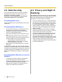
2.3 Privacy and Right of
Publicity
By installing and using this device, you are responsible
for maintaining the privacy and usage rights of images
and other data (including sound picked up by the
microphone). Use this device accordingly.
•
Keep a separate record of all information stored in the
contact list.
Preventing Data Disclosure
•
Do not place this device in a location that can be
accessed or removed without authorisation.
• If important information is saved on this device,
store it in an appropriate location.
• Do not store sensitive personal information in the
unit.
• In the following situations, make a record of the
information stored in the contact list and return the
unit to the state it was in when purchased.
– Before lending or disposing of the unit
– Before handing the unit over to a third party
– Before having the unit serviced
• Make sure the unit is serviced by only a certified
technician.
This device can register and store personal data (the
contact list, connection history, etc.). In order to prevent
the disclosure of data stored on this device, make sure
to delete all data that is registered and stored on this
device prior to disposing of, lending, or returning this
device.
Preventing Data Disclosure over the
Network
•
•
•
12
To ensure the security of private conversations,
only connect the unit to a secure network.
To prevent unauthorised access, only connect the
unit to a network that is properly managed.
Make sure all computers connected to the unit
employ up-to-date security measures.
Installation Manual
•
Privacy is generally said to be, "A legal guarantee
and right not to have the details of one’s personal
life unreasonably publicised, and the right to be able
to control information about oneself. In addition,
right of publicity is a right not to have a likeness of
one’s face or figure photographed and publicised
without consent".
When the Automatic Answer feature is enabled,
transmission begins as soon as a video conference
call is received. The receiver of the video
conference call will begin transmitting as soon as
the video conference call is received at any time,
from any caller. Please be aware when the
Automatic Answer feature is enabled, there is a risk
that due to an unexpected, automatically answered
video conference call, privacy rights may be
violated or sensitive information may be transmitted
to unauthorised parties.
3 Included and Optional Accessories
3 Included and Optional Accessories
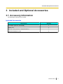
3.1 Accessory Information
The following accessories are included:
Included Accessories
Accessories
Quantity
AC adaptor (Part No.: PNLV6506)
1
Power cord
1
Remote control (Part No.: N2QAYB000674)
1
Batteries (R6 [AA] dry cell)
2
Installation Manual
13
3 Included and Optional Accessories
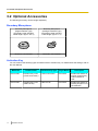
3.2 Optional Accessories
The following accessory can be bought separately:
Boundary Microphone
Boundary Microphone
(Digital Interface Type)
(Proprietary cable included.
Cable length: approx. 8.5 m)
Boundary Microphone
(Analogue Interface Type)
(Proprietary cable included.
Cable length: approx. 7 m)
Model No.: KX-VCA001
Model No.: KX-VCA002
Activation Key
You can enhance the following types of features with an activation key. For details about the settings, refer to
the User Manual.
Model No.
14
Product Name
Activation Key Type
Target Model
Description
KX-VCS301
Activation Key Card
(4-Point Connection)
4-Point Connection
KX-VC300
Enables the feature for
making multiple-party
video conference
calls.
KX-VCS401
Activation Key Card
(1080 Full HD)
1080 Full HD
KX-VC300
Enables the feature for
sending images in Full
HD resolution.
Installation Manual
4 Part Names and Usage
4 Part Names and Usage
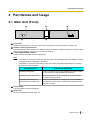
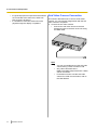
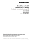
4.1 Main Unit (Front)
A
D
B
C
E
Power LED
Shows the power status. The LED is green when the power is on and off when the power is off.
Remote Control Signal Receiver
Receives Remote Control signals. The maximum range of reception is approximately 8 m from front of the
unit, and approximately 3 m from 20° on each side, total 40°.
Headset Input-Output Terminal
Used to connect a headset to the unit (Page 23).
Note
•
•
If a headset is connected, audio from the other party can be heard through the headset. Audio is
not played through the display or speakers.
If a headset is connected, how audio is sent to the other party differs depending on the type of
devices connected as follows:
Connected Device
Audio Sent to Other Party
Boundary Microphone
Audio is picked up only by the headset microphone. Audio
is not picked up by the Boundary Microphones.
General-purpose microphone
Both the general-purpose microphones and the headset
microphone pick up audio.
Boundary Microphone and
general-purpose microphone
Both the general-purpose microphones and the headset
microphone pick up audio. The Boundary Microphones do
not pick up audio.
Power button
Turns the power on and off (Page 26).
Status LED
Shows the operational status of the unit.
Installation Manual
15
4 Part Names and Usage
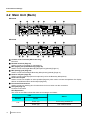
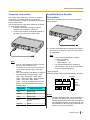
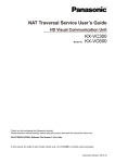
4.2 Main Unit (Back)
KX-VC600
A
H
B
I
J
C
D
K
E
L
F
M
N
G
O
KX-VC300
B
H
I
J
D
K
E
L
F
M
N
G
O
Camera Control terminal (KX-VC600 only)
Not used.
RS-232C terminal (Page 37)
Used to connect a computer for maintenance.
MIC (Digital) jack (KX-VC600 only) (Page 20)
Used to connect the Digital Boundary Microphone (optional) (Page 14).
MIC (Analog) jack (Page 20)
Used to connect the Analogue Boundary Microphone (optional) (Page 14).
Audio In L/R jack (Page 20)
Used to connect general-purpose microphones (not for the Boundary Microphone).
Audio Out L/R jack
Used to connect an amplifier or active speaker (Page 25). Also used to connect the speakers of a display
without an HDMI terminal for audio output (Page 26).
Functional Earth terminal
Used to connect an earthing wire for when there is a lot of noise over the connection.
LAN jack (Page 21)
Connect a LAN cable.
LED Explanation
The colour of the LEDs indicate the status of the network, as follows:
LED
Status
Position
Left
16
Installation Manual
Colour
Green (on)
Link is being established
Green (off)
Link is disconnected
4 Part Names and Usage
LED
Status
Position
Colour
Right
Amber (flashing)
Data is being transmitted
USB jack (Page 35)
Used to connect a USB memory device for saving the operation log and for updating the software.
RGB terminal (Page 25)
Used to connect a computer for sending screens to participants.
Main Camera terminal (Page 20)
Connect the main video camera with an HDMI cable.
Sub Camera terminal (Page 24)
Used to connect a second, sub video camera with an HDMI cable for sharing video contents apart from
the main video camera.
HDMI terminal (Page 20)
Used to connect to the display with an HDMI cable.
Component terminal (Page 26)
Used to connect to the display with a component video cable.
DC IN (Page 21)
Connect the AC adaptor’s DC cord.
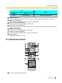
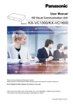
4.3 Remote Control
A
B
C
D
E
F
L
M
N
O
P
Q
R
G
H
S
I
J
T
U
K
Press to enter screen standby mode.
Installation Manual
17
4 Part Names and Usage
Press to show your computer’s screen on your and the other party’s display during a video conference call.
When not on a video conference call, the computer screen is shown on your display only.
Press to show the sub video camera’s images on your and the other party’s display during a video
conference call. When not on a video conference call, the sub video camera’s images are shown on your
display only.
Press to make or manually answer video conference calls.
Press to move the cursor and select items.
Press to display the Home screen.
Press to select the feature assigned to each colour. Available features are displayed in the guide area.
Press to adjust the volume during a video conference call. Press [+] to increase and [–] to decrease the
volume.
Used for controlling a PTZ (Pan, Tilt, Zoom) camera or a FIX camera either at your end or the other
party’s end.
Press to display the connection status of the network and peripheral devices.
Press to dial or perform settings where inputting digits/characters is required.
Press to display/hide information about the other party, guide area and duration, during a video conference
call.
Press to change the layout of the screen during a video conference call.
Press to return to the main video camera after showing images from a computer or sub video camera.
Press to display the Menu screen.
Press to end a video conference call.
Press to confirm the selected item or entered information.
Press to return to the previous screen.
Press to select a tone (equaliser) setting during a video conference call.
Press to mute the microphone during a video conference call, so that the other party cannot hear your
voice.
Press to display your contact list. This can be pressed while the following screens are displayed:
• Home screen
• Menu screen
• Computer’s screen/sub video camera’s image (when not on a video conference call)
18
Installation Manual
5 Connection and Preparation
5 Connection and
Preparation
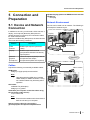
5.1 Device and Network
Connection
In addition to the unit, you will need a video camera, a
display, a microphone (Boundary Microphone or
general-purpose microphone) and connection cables
for visual communication.
Apart from the Boundary Microphone, the other devices
must meet the following conditions:
Device
speaker/display [without an HDMI terminal and with
speakers]):
RCA plug
Network Environment
The unit can be used over an intranet. The following is
an example of network layout.
Video camera
Display
Condition
Video
Camera
HDMI output required (resolution:
1080i)
Display
HDMI/component/D terminal
(component/D terminal conversion)
input required
Generalpurpose
microphone
Line level output required (In case of
microphone level output,
microphone amplifier also required)
Microphone
Intranet
Cables
Prepare the following commercially available cables:
HDMI cable:
Category 2 (high speed) recommended
Video camera
Microphone
Note
•
Use cables with the HDMI logo (certified
HDMI cables) for HDMI connection. Using
non-certified cables may adversely affect
operation.
Display
LAN cable:
100BASE-TX (full duplex)
Category 5 or greater
VGA cable (for computer connection when using
the secondary video source):
15-pin mini D-Sub
Note
•
Ensure that the cables match the sockets of
both the unit and your computer.
Stereo pin plug cable (for connecting a
general-purpose microphone/amplifier/active
Installation Manual
19
5 Connection and Preparation
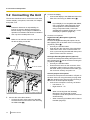
5.2 Connecting the Unit
This section describes how to connect the main video
camera, display, microphone, LAN cable, AC adaptor
and power cord.
2. Connect the display.
• Connect the display to the HDMI terminal on the
back of the unit using an HDMI cable (B).
Note
•
Notice
•
•
Panasonic assumes no responsibility for
injuries or property damage resulting from
failures arising out of improper installation or
operation inconsistent with this documentation.
Use only the included power cord.
Note
•
Make sure to read the instruction manuals for
all devices being connected.
F
G
To a switching
hub
C
D
A
To an AC outlet
E
B
To a display
To each device
To a general - purpose microphone
1. Connect the main video camera.
• Connect the main video camera to the Main
Camera terminal on the back of the unit using
an HDMI cable (A).
20
Installation Manual
If your display is not compatible with HDMI,
use a component cable (Page 26). Since
sound signals are not transmitted when
using a component cable, connect an
amplifier/active speaker (Page 25), or use
the display’s speakers (Page 26).
3. Connect a microphone.
Digital Boundary Microphone (optional)
(KX-VC600 only)
Connect the Digital Boundary Microphone to the
MIC (Digital) jack on the back of the unit using the
proprietary cable (C).
• Use only the included cable.
• Push and turn the connector of the proprietary
cable until it clicks. If the connector does not
click, try reconnecting the cable with the top and
bottom of the connector reversed.
Analogue Boundary Microphone (optional)
Connect the Analogue Boundary Microphone to the
MIC (Analog) jack on the back of the unit using the
proprietary cable (D).
• Use only the included cable.
• Ensure that the arrow on the connector of the
proprietary cable is facing up when you insert
the cable. When you disconnect the cable, grip
the connector securely and pull it out.
General-purpose microphone
Connect the microphone to the Audio In L/R jack on
the back of the unit using the stereo pin plug cable
(E) after amplifying the signal to line level using a
device such as a microphone amplifier.
• Connect the microphone correctly, as follows:
– Left channel ® L
– Right channel ® R
Note
•
•
When connecting both the Boundary
Microphone and a general-purpose
microphone, both microphones can be used
simultaneously.
When connecting a headset, refer to "About
Headset (Page 23)".
5 Connection and Preparation
4. Connect to the network.
• Connect a switching hub to the LAN jack on the
back of the unit using a category 5 or greater
LAN cable (F).
Note
•
•
•
•
System Layout Examples
Display and Main Video Camera
Place the display and main video camera at the same
side of the room.
Set the switching hub to Auto Negotiation
mode.
If the system is set to 100M Full Duplex, it
is necessary to change the system setting
(Page 38).
Do not connect to a switching hub set to Half
Duplex.
For more details about switching hubs, refer
to the documentation for the switching
hubs.
5. Connect the power cord to the AC adaptor.
• Use only the power cord included with the unit.
6. Insert the AC adaptor’s DC cord (G) into the DC IN
terminal on the back of the unit.
• Use only the AC adaptor included with the unit.
7. Plug in the power cord into the power outlet.
• Choose an outlet that is convenient for
plugging/unplugging.
Note
•
If you use speakers, refer to "Amplifier/Active
Speaker Connection" (Page 25).
Digital Boundary Microphones (KX-VC600
only)
Up to 4 Digital Boundary Microphones can be
connected in cascade. There are no separate terminals
for input and output on the Boundary Microphones.
Also, an Analogue Boundary Microphone and
general-purpose microphones can be used
simultaneously.
Note
•
Make sure that the microphones are placed at
least 1 m away from the display and speakers.
Installation Manual
21
5 Connection and Preparation
•
Do not connect more than 4 Digital Boundary
Microphones. Doing so will cause all Digital
Boundary Microphones to stop working. If an
Analogue Boundary Microphone is also
connected, all audio input from the Analogue
Boundary Microphone will also stop working.
If both of the following conditions are met, the
output sent to the other party will be stereo;
otherwise, monaural:
– The bandwidth is higher than approximately
1.8 Mbps in a 2-party video conference call
with the HD Visual Communication Unit
using SIP.
– The MIC position is set automatically or
manually to collect a sound in stereo. (For
details about setting the MIC position, refer
to the User Manual.)
If a headset is connected, audio from the
headset microphone is given priority, and audio
from Digital Boundary Microphones is no longer
picked up.
•
•
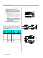
The range of each microphone (the radius of the circle
with a microphone at the centre) varies according to the
level of surrounding and the number of microphones
being used. Place microphones accordingly, referring
to the following table.
22
Noise
level/
Micro–
phone
A quiet
room
(40
dBsplA)
A regular
room
(45
dBsplA)
A noisy
room
(50
dBsplA)
1
approx.
3m
approx.
2.2 m
approx.
1.2 m
2
approx.
2.8 m
approx.
1.5 m
approx.
1m
3
approx.
2.3 m
approx.
1.3 m
—
4
approx.
2m
approx.
1.1 m
—
Installation Manual
Layout examples (a regular room)
(the grey circle indicates the microphone’s range):
Display
4m
Microphone
Display
4m
4m
Microphone
Microphone
4m
4m
Microphone
Microphone
4m
Microphone
Display
5 Connection and Preparation
4m
Microphone
4m
4m
Microphone
Display
Microphone
4m
Noise
level/
Micro–
phone
A quiet
room
(40
dBsplA)
A regular
room
(45
dBsplA)
A noisy
room
(50
dBsplA)
1
approx.
2m
approx.
1.5 m
approx.
1m
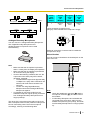
Layout examples (a regular room)
(the grey circle indicates the microphone’s range):
Microphone
Display
2m
Microphone
Analogue Boundary Microphones
You can connect 1 Analogue Boundary Microphone.
Also, Digital Boundary Microphones and
general-purpose microphones can be used
simultaneously.
Approx.
60°
60
About 60° around the connector side is outside the
microphone’s range.
About Headset
You can connect a headset to the headset jack on the
front of the unit.
A
B
Note
•
•
•
•
Make sure that the microphone is placed at
least 1 m away from the display and speakers.
Make sure that the microphone is placed with
its connector facing the display.
If both of the following conditions are met, the
output sent to the other party will be stereo;
otherwise, monaural:
– The bandwidth is higher than approximately
1.8 Mbps in a 2-party video conference call
with the HD Visual Communication Unit
using SIP.
– You are not using Digital Boundary
Microphones and an Analogue Boundary
Microphone together.
If a headset is connected, audio from the
headset microphone is given priority, and audio
from Analogue Boundary Microphones is no
longer picked up.
The range of the microphone (the radius of the circle
with a microphone at the centre) varies according to the
level of surrounding noise. Place the microphone
accordingly, referring to the following table.
Headset
Note
•
•
Check the headphone connector (A) and the
microphone connector (B), and then connect
the headset.
If a Boundary Microphone and a headset are
connected at the same time, audio from the
headset microphone is given priority, and audio
from Boundary Microphones is no longer picked
up.
Installation Manual
23
5 Connection and Preparation
•
•
If a general-purpose microphone and a headset
are connected at the same time, audio from
both sources is picked up.
If a headset is connected, audio will not be
played through the display or speakers.
Sub Video Camera Connection
This section describes how to connect a sub video
camera. You can transmit images taken with the sub
video camera to all parties.
1. Connect the sub video camera.
• Connect the sub video camera to the Sub
Camera terminal on the back of the unit using
an HDMI cable.
Note
•
•
•
24
Installation Manual
You can connect/disconnect the sub video
camera during a video conference call.
Only video cameras that are
HDMI-compatible (output resolution: 1080i)
can be connected.
For details on how to use the sub video
camera for visual communication, refer to
the User Manual.
5 Connection and Preparation
Computer Connection
This section describes how to connect a computer.
Connecting a computer allows you to show the
computer screen’s images on the display and transmit
them to other parties.
You can transmit the computer’s images to all parties.
1. Connect the computer.
• Prepare a VGA cable making sure that it
matches your computer’s connector.
• Connect the computer to the RGB terminal on
the back of the unit using a VGA cable.
Amplifier/Active Speaker
Connection
This section describes how to connect an amplifier/
active speaker.
1. Connect the amplifier/active speaker to the Audio
Out L/R jack on the back of the unit using a stereo
pin plug cable.
Note
•
Note
•
•
•
You can connect/disconnect the computer
during a video conference call.
For details on how to use the computer for
visual communication, refer to the User
Manual.
One of the following resolutions is required
for transmitting computer images: VGA
(640 ´ 480), SVGA (800 ´ 600), XGA
(1024 ´ 768), HD (1280 ´ 720), or WXGA
(1280 ´ 768, 1280 ´ 800). SXGA
(1280 ´ 1024) is not supported. For more
details on supported resolutions, see the
following table.
Resolution
•
Connect the amplifier/active speaker
correctly, as follows:
– Left channel ® L
– Right channel ® R
For more details about the amplifier or
active speaker, refer to the documentation
for the corresponding device.
Layout example:
Place the speakers either side of the display, as follows:
Speaker
Display
Main
video
camera
Microphone
Refresh rate (Hz)
VGA
60/72/75/85
SVGA
60/72/75/85
XGA
60/70/75/85
HD
49.827/50/59.855/
59.941
WXGA
60/75
Speaker
Notice
•
Place the speakers either side of the display. If
you place the display at the front of the room
and the speakers at the back, the microphone’s
left/right spatial direction may be reversed, and
the orientation of the image and sound will not
match on the other party’s side.
Installation Manual
25
5 Connection and Preparation
Connecting the Display with a
Component Cable
If your display does not have an HDMI terminal, use a
component cable for connection.
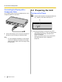
5.3 Preparing the Unit
Turning on the Power
Note
•
Confirm that the power of all peripheral devices
(e.g., display, main video camera) is on.
1
1. Press the Power button on the front of the unit.
• The Power LED turns on. Then, the Status LED
1. Connect the display to the Component terminal on
the back of the unit using a component cable.
Note
•
26
To use the display’s speakers to output audio,
connect the display to the Audio Out L/R jack
(Page 16) on the back of the unit using a stereo
pin plug cable.
Installation Manual
•
starts flashing blue slowly, and the Home
screen is displayed.
When you turn the power on for the first time,
the Initial Settings screen is displayed
(Page 32).
5 Connection and Preparation
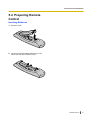
5.4 Preparing Remote
Control
Inserting Batteries
1. Open the cover.
2. Insert the included batteries (R6 [AA] dry cell),
minus side first, then close the cover.
Installation Manual
27
6 Settings and Confirmation
6 Settings and Confirmation
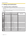
6.1 Inputting Letters and Numbers
You can use the remote control to input letters and numbers. The following tables detail the characters and
numbers that can be input. The language that can be input depends on which language is selected through
system settings.
Press the indicated button repeatedly to cycle through the characters and numbers assigned to that button
until the character you want to input is displayed. If you want to input another character using the same button,
press [ ] to move the input cursor to the right.
Table 1 Chinese
Latin Mode
Button
Number Mode
Uppercase-preferred Mode
28
Lowercase-preferred Mode
1
1
1
AB C a b c 2
a b cAB C 2
2
DEFdef 3
defDEF3
3
GHIghi4
ghiGHI4
4
JKLjkl5
jklJKL5
5
MNOmno6
mnoMNO6
6
PQ RSpqrs7
pqrsPQ RS7
7
TUVtuv8
tuvT UV8
8
WXYZ wxyz9
wxyzWXYZ 9
9
0
0
0
(Normal space)
(Normal space)
.@:;”= +< >
.@:;”= +< >
.@:;”= +< >
#_-&$\%~^!?/‘(),[]{|}’
#_-&$\%~^!?/‘(),[]{|}’
#_-&$\%~^!?/‘(),[]{|}’
Installation Manual
6 Settings and Confirmation
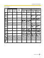
Table 2 English
Latin Mode
Button
Uppercase
-preferred
Mode
Lowercase
-preferred
Mode
1
1
Extended Character 1
(Western Europe) Mode
Uppercase Lowercase
-preferred
-preferred
Mode
Mode
Extended Character 2
(Eastern Europe) Mode
Uppercase Lowercase
-preferred
-preferred
Mode
Mode
1
1
1
1
1
aàáâãäåæ
bcçAÀÁÂ
ÃÄÅÆBC
Ç2
GHIÍghií4
ghiíGHIÍ4
Number
Mode
ABCabc2
abcABC2
2
AÀÁÂÃÄÅ
ÆBCÇaàá
âãäåæbcç
2
DEFdef 3
defDEF3
3
DEÈÉÊËF deèéêëfD
deèéêëf3 EÈÉÊËF3
GHIghi4
ghiGHI4
4
JKLjkl5
jklJKL5
5
MNOmno6 mnoMNO6 6
PQRSpqr
s7
pqrsPQR
S7
7
TUVtuv8
tuvTUV8
8
WXYZwxy wxyzWXY
Z9
z9
JKLjkl5
jklJKL5
MNÑOÒÓ
ÔÕÖØŒ
mnñoòóô
õöøœ6
mnñoòóôõ
öøœMNÑ
OÒÓÔÕÖ
،6
9
0 Space
0 Space
0
0 Space
0 Space
0 Space
0 Space
.@:;"= +
<>
#_-&$\%
~^!?/`(),
[]{|}'
.@:;"= +
<>
#_-&$\%
~^!?/`(),
[]{|}'
.@:;"= +
<>
#_-&$\%
~^!?/`(),
[]{|}'
.@:;"= +
<>
#_-&$\%
~^!?/`(),
[]{|}'
.@:;"= +
<>
#_-&$\%
~^!?/`(),
[]{|}'
.@:;"= +
<>
#_-&$\%
~^!?/`(),
[]{|}'
.@:;"= +
<>
#_-&$\%
~^!?/`(),
[]{|}'
Installation Manual
29
6 Settings and Confirmation
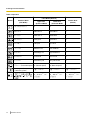
Table 3 Japanese
Latin Mode (Normal)
Button
30
Katakana Mode
(Full-Width)
Uppercase
-preferred Mode
Number Mode
(Normal)
Lowercase
-preferred Mode
アイウエオァィゥェォ
1
1
1
カキクケコ
AB C a b c 2
a b cAB C 2
2
サシスセソ
DEFdef 3
defDEF3
3
タチツテトッ
GHIghi4
ghiGHI4
4
ナニヌネノ
J K Lj k l 5
j k l J K L5
5
ハヒフヘホ
MNOmno6
mnoMNO6
6
マミムメモ
PQRSpqrs7
pqrsPQRS7
7
ヤユヨャュョ
TUVtuv8
tuvTUV8
8
ラリルレロ
WXYZwxyz9
wxyzWXYZ9
9
ワヲンヮ−(Full-width space) 0(Normal space)
0(Normal space)
0
゛
(Voicing mark)
゜
(Half-voicing mark)
.@:;"= +<>
.@:;"= +<>
.@:;"= +<>
#_-&$\%~^!?/`
(),[]{|}'
#_-&$\%~^!?/`
(),[]{|}'
#_-&$\%~^!?/`
(),[]{|}'
Installation Manual
6 Settings and Confirmation
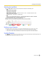
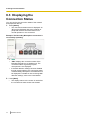
Switching the Input Mode
Each time [B] or [R] is pressed, the input mode will be switched in the following cycle:
• [B]:
(When Chinese is selected)
Latin mode ® number mode
(When English is selected)
Latin mode ® number mode ® extended character 1 mode ® extended character 2 mode
(When Japanese is selected)
Katakana mode ® Latin mode ® number mode
• [R]:
(When Latin mode/extended character 1 mode/extended character 2 mode is selected)
lowercase-preferred mode ® uppercase-preferred mode
The current input mode is displayed in the guide area.
Example: Latin mode and lowercase-preferred mode currently selected
Deleting an Input Character
Press [Y] to delete an input character. The character deleted depends on the position of the cursor:
• If the cursor is to the right of the last character in the line, the last character will be deleted.
• If the cursor is within a line of characters, the character to the right of the cursor will be deleted.
Inserting Characters
Use [ ][ ] to move the cursor to the position where you want to insert characters, and then begin input. The
characters will be inserted at the location of the cursor.
Installation Manual
31
6 Settings and Confirmation
6.2 Initial Settings
After turning the unit on, you need to set the language,
device name, date and time, and network settings.
These settings can be changed later.
1. Press the Power button to turn on the unit.
• The language settings screen is displayed.
2. Press [Enter] and use [
language ("
"
").
][ ] to select the desired
" [default], "English",
3. Press [Enter].
9. Select the item using [
][ ], then input
information.
• Enter the year (4 digits), month (1–2 digits), day
(1–2 digits), time (24 hour display), and select
the date format (Month/Day/Year, Day/Month/
Year, Year/Month/Day) and the hour display
format (12h/24h).
10. Press [G].
11. Select "Yes" using [ ][ ], then press [Enter].
• The network settings screen is displayed.
12. Use [
][
] to select the following items for input:
4. Press [G].
5. Use [ ][ ] to select " " and press [Enter].
• The device name setting screen is displayed.
6. Enter a name for the device (up to 24 characters)
(Page 28).
7. Press [G].
8. Select "Yes" using [ ][ ], then press [Enter].
• The date and time setting screen is displayed.
32
Installation Manual
"IP Address": Use [ ][ ] to select whether the
IP address information for this unit ("IP Address",
"Subnet mask", "Default Gateway") will be
obtained automatically from a DHCP server or will
be set manually.
– "Auto" (default): Obtain the IP address
information automatically.
– "Manual": Set the IP address information
manually.
6 Settings and Confirmation
Note
•
Even if you have selected "Auto", you still
may not be able to acquire an IP address
due to problems such as network
congestion. In this case, "Address is not
assigned" is displayed in the upper right of
the Home screen. Contact your network
administrator.
"IP Address": Enter the IP address of the unit.
"Subnet mask": Enter the subnet mask.
"Default Gateway": Enter the IP address of the
default gateway.
Note
•
•
"IP Address", "Subnet mask", and
"Default Gateway" can be entered only if
"IP Address" is set to "Manual".
If the value for "IP Address", "Subnet
mask", or "Default Gateway" contains 1 or
2 digits numbers, enter these numbers as
they are. Do not enter like [.001].
Example: The IP address is [192.168.0.1].
– Correct entry: [192.168.0.1]
– Wrong entry: [192.168.000.001]
13. Press [G].
14. Select "Yes" using [ ][ ], then press [Enter].
• Settings become effective after the automatic
restart.
Note
•
•
If the IP address or subnet mask contains an
invalid value, a message will appear requiring
you to enter a valid IP address or subnet mask.
A multicast address or broadcast address
cannot be used for the IP address.
Installation Manual
33
6 Settings and Confirmation
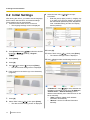
6.3 Displaying the
Connection Status
You can confirm the connection status of the network
and peripheral devices.
1. Press [Status].
• The connections status screen is displayed. An
"X" mark is displayed next to any network or
peripheral devices connection that is not in
normal operation or not connected.
Example: The Boundary Microphone connection is
not normally operating.
•
•
"MIC" displays the connection status of the
Boundary Microphone or headset only. The
connection status of general-purpose
microphones is not displayed.
If the MIC detection setting has been disabled
through system settings, the connection status
of the Boundary Microphone or headset will not
be displayed. For details on how to change MIC
detection settings, refer to the User Manual.
2. Press [Back].
• The display returns to the screen in use before
the connections status screen was viewed.
34
Installation Manual
6 Settings and Confirmation
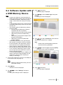
6.4 Software Update with
a USB Memory Device
Note
•
•
•
•
•
•
•
•
•
Contact your dealer for more information on
obtaining the latest firmware and User Manual.
To update the software, make sure you are
using a version later than 3.00 (not including
3.00).
A mass storage class (FAT16 or FAT32 format)
compatible USB memory device can be used
with this unit.
The following types of USB memory devices
cannot be used:
– U3 smart drives (USB memory devices
compatible with the U3 platform)
– USB memory devices with security features
– USB memory devices formatted using
NTFS
– USB memory devices with multiple LUNs
(Logical Unit Numbers)
– USB memory devices formatted with
multiple partitions
USB memory devices are not guaranteed to
fully operate. For details, contact your dealer.
Do not store files in the USB memory device
other than the one for updating the software.
Store the file for updating the software in the
top-most directory of the USB memory device.
To re-connect a USB memory device, make
sure to fully remove the USB memory device
before connecting it again.
To prevent data leakage from the USB memory
device, make sure to erase all data from the
USB memory device before disposing of,
lending, or returning it.
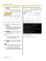
4. Press [ ] three times.
• The fourth page is displayed.
5. Use [
][ ] to select "Admin login" and press
[Enter].
• The login screen is displayed.
6. Use [
][ ] to select "Password", then enter the
administrator password (4–10 digits).
Note
•
Please enter the administrator password
that was set during installation.
7. Use [ ][ ] to select "Login" and press [Enter].
• The admin menu screen is displayed.
1. Connect the USB memory device to the USB jack
on the back of the unit (Page 17).
Note
•
Make sure that the USB memory device is
connected correctly.
2. Press [Menu].
• The Menu screen is displayed.
3. Use [
8. Press [ ] three times.
• The fourth page is displayed.
][ ] to select "Settings" and press
[Enter].
• The system settings screen is displayed.
Installation Manual
35
6 Settings and Confirmation
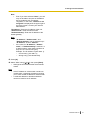
9. Use [
][ ] to select "Software update" and
press [Enter].
• The software update screen is displayed.
The message displayed before the first restart
The message displayed before the second restart
10. Use [
][ ] to select "Software updates" and
press [Enter].
• The system checks for version updates. The
latest software version will be displayed next to
"Available Software version :". Proceed to
step 11 if there is an update available.
11. Use [
][ ] to select "Update Software Now"
and press [Enter].
• A dialogue box to confirm the updating of your
software is displayed.
Note
•
Please carefully read and confirm the
cautions in the dialogue box before
proceeding to the next step.
12. Use [ ][ ] to select "Yes" and press [Enter].
• The update is automatically downloaded and
installed.
Note
•
•
36
While the software is being updated, do not
remove the USB memory device. This could
damage the unit or corrupt the data.
To complete the update, the system will
automatically restart twice. Before each restart,
a message will be displayed as detailed below.
Installation Manual
After the second restart, the system will start up with
the latest software.
13. Remove the USB memory device.
6 Settings and Confirmation
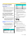
6.5 System Settings
Terminal parameters
Operating Environment
Operating System
• Windows XP (X86/X64) Home/Professional SP2 or
•
later
Windows 7 (X86/X64) Ultimate/Professional/Home
Premium
Compatible Web Browsers/Operating Systems
• Windows Internet Explorer® 7/Windows XP
• Windows Internet Explorer 8/Windows XP
• Windows Internet Explorer 8/Windows 7
6.5.1 How to Perform System
Settings Using a Computer
This section describes how to perform system settings,
such as method of receiving video conference calls,
using a computer.
Note
•
If you want to configure system settings using a
computer, make sure to complete initial settings
using the remote control first. If the initial
settings are not complete, you may not be able
to make settings for some parameters.
3. Select Serial as the connection method.
Terminal parameters
Value
Baud rate
(data transmission speed)
38400
Data
(character bit length)
8 bits
Stop
(stop bits)
1 bit
Flow control
none
Page 39.
7. Enter "service stop", then press [Enter].
• "Can not use during maintenance." is displayed
on the display.
8. Enter a command, then press [Enter] (Page 38).
• Enter a space between commands and
parameter values.
Example:
Command name
set: Change the setting.
get: Display the current value.
Value
9. Enter "syssave", then press [Enter].
• The value is saved as configuration data.
10. Turn the power off, then back on, to restart the unit.
Note
•
•
4. Set the serial port as follows:
none
6. Enter the login password, then press [Enter].
• The default login password is "HDVC_admin".
• For details on changing the login password, see
1. Connect a computer to the RS-232C terminal on the
2. Start a terminal emulator using the computer.
Parity
(parity bits)
5. Enter the login user name, then press [Enter].
• The login user name is "admin".
Starting and Operating a Terminal
Emulator
back of the unit using an RS-232C cable.
• Prepare an RS-232C cable making sure that it
matches your computer’s connector.
• Use a straight cable for the RS-232C cable.
Value
•
•
You will be automatically logged out if there is
no activity for 5 minutes while logged in.
Settings cannot be changed during a video
conference call.
Using the [Ctrl] key when entering commands
may unintentionally activate other computer
features.
Some settings cannot be displayed by entering
terminal emulator commands.
Installation Manual
37
6 Settings and Confirmation
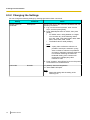
6.5.2 Changing the Settings
You can change the following settings by entering terminal emulator commands.
Setting
Default maximum
bandwidth
Command
defaultiprate
Value
Set an upper limit of the maximum bandwidth that can
be set by customers.
1. Log in to the terminal emulator, enter "service
stop", and then press [Enter].
2. Enter "defaultiprate set max XXXX", then press
[Enter].
• For XXXX, enter a string between 3–5 digits.
You can enter any of the following values:
512, 768, 1000, 1200, 2000, 3000, 4000, 5000,
6000, 7000, 8000, 9000, 10000
• The default value is 9000 (9 Mbps).
Note
•
3-party video conference calls are not
possible if 512 kbps is selected. 4-party
video conference calls are not possible if
512 kbps or 768 kbps is selected. Keep this
in mind when selecting the maximum
bandwidth setting if the customer will
participate in multiple-party video
conference calls.
3. Enter "syssave", press [Enter], then turn the power
off and back on to restart the unit.
LAN mode
lanmode
"0" (default): Sets Auto Negotiation.
"2": Sets 100M Full Duplex.
Note
•
38
Installation Manual
Match this setting with the setting of the
switching hub.
6 Settings and Confirmation
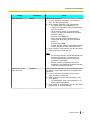
Setting
Login password
Command
passwd
Value
Set the login password.
1. Log in to the terminal emulator, enter "service
stop", and then press [Enter].
2. Enter "passwd set XXXX", then press [Enter].
• For XXXX, enter a string between 4–15
characters. Only ASCII code characters 0x20–
0x7e can be used.
• When entering spaces or single quotation
marks ('), enclose the whole string in double
quotation marks (").
Example: "AAA BBB'CCC"
When entering double quotation marks ("),
enclose the whole string in single quotation
marks (').
Example: 'AAA"BBB'
• Double quotation marks (") and single quotation
marks (') cannot be used in the same string.
3. Enter "syssave", press [Enter], then turn the power
off and back on to restart the unit.
Note
•
•
Administrator menu
login password
guipasswd
For security purposes, change the default login
password the first time you install the unit.
Choose a password that cannot be easily
guessed by a third party.
Keep a record of your password to avoid
forgetting it. The password should be kept safe
to prevent unauthorised access.
Change the login password for the administrator menu
for when the system administrator has forgotten their
password.
1. Log in to the terminal emulator, enter "service
stop", and then press [Enter].
2. Enter "guipasswd set normal XXXXXXXX", then
press [Enter].
• For XXXXXXXX, enter a string between 4–10
digits (default: 00000000).
3. Enter "syssave", press [Enter], then turn the power
off and back on to restart the unit.
Installation Manual
39
6 Settings and Confirmation
Setting
Web port status setting
Command
httpenable
Value
Set the permanent status of the Web port to open or
closed. The default setting is "0" (the Web port is
closed).
1. Log in to the terminal emulator, enter "service
stop", and then press [Enter].
2. When setting the Web port status to open:
Enter "httpenable set defenable 1", then press
[Enter].
Notice
•
Setting the Web port status to always be
open presents a possible security risk, such
as an increased possibility of unauthorised
access. Please gain permission from the
customer before performing the network
settings.
When setting the Web port status to closed:
Enter "httpenable set defenable 0", then press
[Enter].
3. Enter "syssave", press [Enter], then turn the power
off and back on to restart the unit.
Note
•
40
Installation Manual
Even if the Web port status is set to closed, it is
possible to open the Web port for 60 minutes by
entering "webport open" then pressing [Enter].
The Web port will close automatically after 60
minutes.
6 Settings and Confirmation
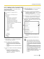
6.5.3 Adding to the Contact List
4. Start a Web browser, then enter the IP address of
the unit in the URL field.
• An authentication screen is displayed.
This section describes how to download, edit and
upload contact list data.
Example of Contact List Data
5. Enter the login user name and login password.
• The login user name is "admin" and the default
•
password is "HDVC_admin".
The Language Selection screen is displayed.
6. Click [English] on the Language Selection screen.
• The System Operation screen is displayed.
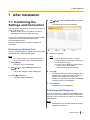
7. Click [download] under [Data Download From
Main Unit] ® [Download contact list] on the System
Operation screen.
9
10
7
•
The contact list data is downloaded to the
computer.
8. Edit the downloaded contact list data on the
computer.
1. Perform steps 1–7 in "Starting and Operating a
Terminal Emulator" (Page 37).
Note
•
2. Enter "webport open", then press [Enter].
• The Web port is opened and the System
•
Operation screen can be accessed using a
browser.
The Web port will close automatically after 60
minutes.
3. Connect a computer to the network containing the
unit.
• Change the computer’s IP address.
Example: If the IP address of the unit is
"192.168.0.1", change the computer’s IP
address to "192.168.0.2".
•
•
The downloaded contact list data is a
XML-format text file. Save the file using
UTF-8 encoding. If you do not use UTF-8
encoding, you may not be able to upload the
contact list data or characters may become
garbled.
If undisplayable characters are saved in the
file, they will not be displayed on the screen.
If you are using the KX-VC300 and have not
used an activation key card (KX-VCS301)
to enable the multiple-party video
conference feature, you cannot use contact
list data that contains 3-party/4-party
contacts.
Installation Manual
41
6 Settings and Confirmation
•
You cannot use a contact list whose version
is older than 1.03 (not including 1.03). The
version of the contact list is displayed in the
<AddressVersion> field of the downloaded
contact list data. If the version of the contact
list is older than 1.03, update the software
of the unit to update the version of the
contact list to 1.03, and then download the
contact list.
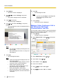
9. Click [Browse…] for [Select a file to upload:] under
[Data Upload To Main Unit] ® [Upload contact
list] on the System Operation screen, then navigate
to the edited data.
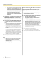
6.5.4 Entering the Device Name
When entering data apart from that which can be
entered using the remote control, follow the procedure
below.
1. Perform steps 1–7 in "Starting and Operating a
Terminal Emulator" (Page 37).
2. Enter "devinfo set name XXXX", then press [Enter].
• For XXXX, enter a device name.
• The following number of characters can be
10. Click [upload] under [Data Upload To Main Unit]
® [Upload contact list] on the System Operation
screen.
• The data is uploaded to the unit and [file upload
success] is displayed on the Web browser.
• If [upload file commit error] is displayed on the
Web browser, the uploaded data may contain
an error. Refer to the error message and correct
the error.
Or, you may be trying to upload a contact list
whose version is older than 1.03. Check the
<AddressVersion> field in the contact list data
that you are trying to upload. If the version of the
software is not 1.03, contact your dealer.
11. Turn the power off and back on to restart the unit.
Note
•
•
42
Make sure you do not access any Web sites
while performing settings on the System
Operation screen.
Make sure to close the browser after finishing
performing settings.
Installation Manual
•
•
displayed on the screen:
– When using Alphabet: Up to 24 characters
– When using Kanji (Chinese characters): Up
to 18 characters
Make sure to set the terminal emulator to use
UTF-8 encoding. If UTF-8 is not set, the entered
information may not be recognised and the
initial screen will be displayed after restart.
If undisplayable characters are set, they will not
be displayed on the screen.
3. Enter "syssave", then press [Enter].
• The value is saved as configuration data.
4. Turn the power off and back on to restart the unit.
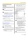
6 Settings and Confirmation
6.6 Remote Access
Settings
2. Enter the login user name and login password.
• The login user name is "admin" and the default
password is "HDVC_admin".
•
The Language Selection screen is displayed.
It is possible to change the settings of the unit from a
separate location via remote access using an intranet.
The following network settings are required to enable
remote access.
3. Click [English] on the Language Selection screen.
• The System Operation screen is displayed.
Notice
4. Click [stop] under [Remote Maintenance
•
4
Note
•
•
Commands] ® [Communication service] on the
System Operation screen.
Please gain permission from the customer
before performing the network settings.
To perform the remote access settings, the unit
must be turned on.
The unit cannot be operated while the remote
access settings are being performed.
6
8
10
11
Making the Web Port Status Open
1. Perform steps 1–7 in "Starting and Operating a
Terminal Emulator" (Page 37).
2. Enter "httpenable set defenable 1", then press
[Enter].
3. Enter "syssave", then press [Enter].
• The value is saved as configuration data.
5. Confirm that [OK] is displayed on the screen, then
click [Back] on the Web browser.
• The System Operation screen is displayed.
Note
•
4. Turn the power off, then back on, to restart the unit.
Allowing HTTP Access
•
Perform network settings so that the unit allows external
HTTP access for maintenance.
6.6.1 Updating Software
Note
•
Contact your dealer for more information on
obtaining the latest firmware and User Manual.
1. From an external maintenance computer, start a
Web browser, then enter the IP address of the unit
in the URL field.
• An authentication screen is displayed.
If [command not available] is displayed, the
unit is on a video conference call. Perform
the settings again after the video
conference call has finished.
If anything else is displayed, follow the
procedure below to restart the system, then
perform the settings again.
1. Click [Back] on the Web browser.
2. Click [restart] under [System Restart]
® [System restart] on the System
Operation screen.
6. Click [view] under [Remote Maintenance
Commands] ® [Check system status] on the
System Operation screen.
7. Confirm that [outOfService] is displayed on the
screen, then click [Back] on the Web browser.
• The System Operation screen is displayed.
Note
•
If [active] is displayed, start again from step
4.
Installation Manual
43
6 Settings and Confirmation
•
If [majorAlarm] or [fatal] is displayed, follow
the procedure below to restart the system,
then perform the settings again.
1. Click [Back] on the Web browser.
2. Click [restart] under [System Restart] ®
[System restart] on the System Operation
screen.
8. Click [view] under [Firmware Update] ® [Check
installed firmware version] on the System Operation
screen.
• Confirm the version of the software you are
using.
9. Click [Back] on the screen.
• The System Operation screen is displayed.
10. Click [Browse…] under [Firmware Update] ®
[Select a file to upload:] on the System Operation
screen, then navigate to the latest firmware.
11. Click [start] under [Firmware Update] ® [Execute
firmware update] on the System Operation screen.
• The software update starts. It takes about 12
minutes. When the update is complete, the unit
will automatically restart.
12. Perform steps 1–8 to confirm that the software has
been updated.
13. Click [Back] on the screen.
• The System Operation screen is displayed.
14. Click [restart] under [System Restart] ® [System
restart] on the System Operation screen.
Note
•
•
Make sure you do not access any Web sites
while performing settings on the System
Operation screen.
Make sure to close the browser after finishing
performing settings.
6.6.2 Updating the Contact List
1. Perform steps 1–7 in "6.6.1 Updating Software"
(Page 43).
2. Perform steps 7–11 in "6.5.3 Adding to the Contact
List" (Page 41).
44
Installation Manual
Note
•
•
•
Make sure you do not access any Web sites
while performing settings on the System
Operation screen.
Make sure to close the browser after finishing
performing settings.
Make sure to set the Web port status to closed
after finishing performing settings. For details,
refer to "When setting the Web port status to
closed: (Page 40)".
7 After Installation
7 After Installation
7.1 Confirming the
Settings and Connection
4. Use [
][ ] to select "Network Test" and press
[Enter].
• The network test screen is displayed.
You can perform the following checks before making a
video conference call:
– Network test to check your network connection
– Self diagnosis to check image and sound
You can also confirm the connection by making a video
conference call to the Panasonic HD Visual
Communication test site.
Follow the steps below to check the settings and
connection:
Performing a Network Test
You can confirm whether a network connection can be
established with a particular IP address.
Note
•
5. Enter an IP address.
Note
You cannot perform a network test from the
contact list screen or the call history screen.
•
1. Press [Menu].
• The Menu screen is displayed.
2. Use [
][ ] to select "Settings" and press
[Enter].
• The system settings screen is displayed.
3. Press [ ] three times.
• The fourth page is displayed.
If the IP address contains 1 or 2 digit
numbers, enter these numbers as they are.
Do not enter like [.001].
Example: The IP address is [192.168.0.1].
– Correct entry: [192.168.0.1]
– Wrong entry: [192.168.000.001]
6. Press [R].
• The network test starts. After the network test is
finished, if the network test was successful or
timed out, the details of the results are
displayed. If the network test failed, a message
indicating the failure is displayed.
7. Press [Home].
• The Home screen is displayed.
Performing Self Diagnosis
You can check how your image will be displayed and
how your voice will be heard to the other party before
starting a video conference call, using your own display
and speakers.
Note
•
Self diagnosis can be performed even when a
headset is connected.
Installation Manual
45
7 After Installation
1. Press [Menu].
• The Menu screen is displayed.
2. Use [
][
] to select "Settings" and press
[Enter].
• The system settings screen is displayed.
3. Press [ ] three times.
• The fourth page is displayed.
6. Press [R].
• The self diagnosis ends.
Note
•
If you do not press [R], the self diagnosis
will automatically end after about
10 minutes.
7. Press [Home].
• The Home screen is displayed.
4. Use [
][ ] to select "Self Diag." and press
[Enter].
• The self diagnosis screen is displayed with the
dialogue box.
Making a Video Conference Call to
the Panasonic HD Visual
Communication Test Site
You can make a video conference call to the Panasonic
HD Visual Communication test site by entering the IP
address using the remote control.
1. Press [Menu].
• The Menu screen is displayed.
2. Select "Manual Dial" using [
][ ], then press
[Enter].
• The Input screen is displayed.
Note
•
•
You can hide or display the dialogue box by
pressing [B].
Set the microphone at least 1 m away from
the speakers.
5. Press [R].
• The self diagnosis starts.
Note
•
•
•
•
•
46
Check the image that is displayed from the
main video camera.
To avoid feedback, slowly raise the volume
using the remote control’s [+] button.
When someone speaks into the
microphone, confirm whether the sound
plays back through the speakers.
During self diagnosis, all Boundary
Microphones will be set to "Center stereo".
During self diagnosis, the tone will be set to
"Standard".
Installation Manual
3. Select "Multi-Point" using [
4. Select "No" using [
][
5. Select "Site 1" using [
][
].
].
][
].
6. Enter the IP address.
7. Use [
][
] to select "Call Type".
8. Use [
][
] to select "SIP" or "H.323".
7 After Installation
9. Press [Start] to start the video conference call.
• You can also start the video conference call by
pressing [Enter].
10. When you want to end the video conference call,
press [End].
• The Home screen is displayed.
Installation Manual
47
7 After Installation
7.2 Adjusting Conditions in Call Environment
For optimum performance, it may be necessary to make the following adjustments.
Adjusting the Image Quality of the Video Camera
Follow the procedure below to adjust the image quality of the video camera.
Note
•
Make sure that display and main video camera are turned on.
1. Press the Power button to turn on the unit.
• The Home screen is displayed. The Home screen displays the video from the main video camera.
2. Operate the video camera to perform the following adjustments:
– Disable automatic face recogniser
– Enable image stabiliser
– Disable Intelligent Auto (iA)
– Adjust white balance and Iris
Adjusting the Volume
The volume on the unit is related to the volume of the display. Select the volume level of the unit through system
settings, and then adjust the volume level of the display to a desired level. If the volume of the display is not
set to an appropriate level, it may be too loud when using the display for other purposes, such as watching TV.
For details on how to change the volume level of the unit, refer to the User Manual.
Adjusting the Location of the Microphone(s)
If the other party cannot hear you well during a video conference call, move the microphone(s) accordingly.
48
Installation Manual
8 Troubleshooting
8 Troubleshooting
If a problem is occurring with the operation of the unit, check here for possible solutions. Before proceeding
check all connections to make sure they are secure (Page 20), and that power is flowing from the outlet that
the unit is plugged into.
8.1 Basic Operation
Problem
Cause and Solution
The power does not turn on.
• The power cord is not plugged into the outlet.
→ Plug the power cord into the outlet.
There is no display.
• A cable or cord is not properly connected.
→ Check that all cables to the unit are connected properly (Page 20).
Perform self diagnosis, and check the performance of the video camera
and the display that are connected to the unit (Page 45).
• The main video camera is not turned on.
→ Turn on the main video camera.
• The display is not turned on, or the input that the unit is connected to is
not selected.
→ Turn on the display, and select the input that the unit is connected to.
• The unit is in screen standby mode.
→ Pushing a button on the remote control, or receiving a video conference
call will end standby mode and the display will return.
Note
•
The network administrator can set the length of time until the unit
enters screen standby mode. For details, refer to the User Manual.
•
When connecting a device equipped with HDCP (High-bandwidth
Digital Content Protection), only a blue or blue/black screen may be
displayed.
→ If an image is not correctly displayed, do not connect an
HDCP-equipped device.
The area at the edges of the
screen is not displaying
properly.
• The display is not set to show the full image.
→ Set the display to show images at full screen. For detailed procedure,
read the instruction manual for the display.
When connecting to an MCU or non-Panasonic video conference
system, the other party’s image may be trimmed, depending on the
device used by the other party.
→ Contact your dealer.
•
Note
•
In Layout 1 during a 3-party video conference call, the left and right
edges of the image are trimmed. In Layout 2 during a 4-party video
conference call, the edges of the image are trimmed and only the
centre of the image is displayed. For details, refer to the User
Manual.
Installation Manual
49
8 Troubleshooting
Problem
Cause and Solution
The aspect ratio of the image
is not correct.
•
Operation is unresponsive or
incorrect.
•
→
•
→
•
→
Cables or cords may not be connected properly.
Check that all cables to the unit are connected properly (Page 20).
An error has occurred.
Turn off the unit and restart it.
There may be a problem with your communication lines.
Contact your dealer.
The remote control is
unresponsive.
•
→
•
→
•
→
The batteries are depleted.
Replace with new batteries.
The remote control is being used out of the signal reception range.
Make sure to use the remote control within the signal reception range.
The remote control ID differs between the unit and the remote control.
Change the settings so that the remote control ID of the unit and the
remote control match. For details on how to change the remote control
ID settings, refer to the User Manual.
The FIX camera is set to receive remote control signals.
When using the remote control, be sure to point it at the remote control
signal receiver of the FIX camera.
Change the "FIX Cam's Remote Ctrl Rcvr" setting to "OFF". For details,
refer to the User Manual.
The unit is set to receive remote control signals.
When using the remote control, be sure to point it at the remote control
signal receiver of the unit (Page 15).
Change the "FIX Cam's Remote Ctrl Rcvr" setting to "ON". For details,
refer to the User Manual.
When connecting to an MCU or non-Panasonic video conference
system, the aspect ratio of the image displayed on the other party’s
device may not be displayed correctly, depending on the device used.
→ Adjust the aspect ratio accordingly. For details, refer to the User
Manual.
•
→
→
•
→
→
You cannot control your own
video camera (main or sub
video camera) with the
remote control.
50
Installation Manual
• Your video camera is not a video camera supported by this unit.
→ Use a video camera that is supported by this unit. For details, contact
your dealer.
You are trying to use a function that is not supported by your video
camera. For example, you tried to use the pan function with a video
camera that supports only the zoom function.
→ Check whether your video camera supports the function you are trying
to use.
• When you connect both the main video camera and sub video camera
to your unit, you may become unable to control one or both of the video
cameras.
→ Disconnect the HDMI cable of the video camera you cannot control,
and then connect that video camera’s HDMI cable again.
•
8 Troubleshooting
Problem
You cannot control the other
party’s video camera (main or
sub video camera) with the
remote control.
Cause and Solution
•
→
•
→
•
→
•
→
•
→
•
→
The other party’s video camera is not a video camera supported by this
unit.
Ask the other party to use a video camera that is supported by this unit.
For details, have the other party contact their dealer.
"CAM ctrl from remote site(s)" is set to "OFF" on the other party’s unit.
Ask the other party to set "CAM ctrl from remote site(s)" to "ON" on their
unit.
You are trying to use a function that is not supported by the other
party’s video camera. For example, you tried to use the pan function
with a video camera that supports only the zoom function.
Check whether the other party’s video camera supports the function
you are trying to use.
When the other party connects both the main video camera and sub
video camera to their unit, you may become unable to control one or
both of their video cameras.
Ask the other party to disconnect the HDMI cable of the video camera
you cannot control, and then connect that video camera’s HDMI cable
again.
One of the parties is using a unit with an incompatible software version.
Check the software version of all parties. Update the unit so that the
versions match.
The other party is using a non-Panasonic video conference system.
If the other party uses a non-Panasonic video conference system, some
operations may not be possible or some operations may not function
as expected.
Installation Manual
51
8 Troubleshooting
Problem
Cannot connect with another
party.
Cause and Solution
• The LAN cable is not connected properly.
→ Check that it is connected to the unit properly (Page 21). Perform a
•
→
→
•
→
•
→
•
→
•
→
•
→
•
→
•
→
•
→
52
Installation Manual
network test by entering a particular IP address (e.g., the other party or
a switching hub), and then confirm the network connection (Page 45).
The maximum bandwidth setting is incorrect.
3-party video conference calls are not possible if 512 kbps is selected.
4-party video conference calls are not possible if 512 kbps or 768 kbps
is selected. Check your maximum bandwidth setting, and select a value
that is appropriate for your network environment.
If you are trying to connect to a non-Panasonic video conference
system, a connection might not be possible depending on either your
or the other party’s bandwidth settings. Either check your settings and
change them, or have the other party do the same. If you change your
own settings, you should register the new information as a local site.
For details, refer to the User Manual.
The call type setting is incorrect.
Set the call type setting so that it is the same as the other party’s. For
details, refer to the User Manual.
The SIP settings are incorrect.
Check the SIP settings. For details about SIP settings, refer to the User
Manual. After you check the SIP settings, if you still cannot connect to
the other party, contact your network administrator.
The ID and password for digest authentication are incorrect.
Check that the values specified for "Authentication ID" and
"Authentication Password" are correct. For details, refer to the User
Manual.
The "SIP Transport Protocol" setting is different from the other party’s.
Set the "SIP Transport Protocol" setting so that it is the same as the
other party’s. For details, refer to the User Manual.
The local site settings are incorrect.
Confirm the local site settings. Specify the settings that are appropriate
for your usage environment. For details, refer to the User Manual.
The IP address is not entered correctly.
Confirm that the other party’s IP address is correctly entered.
The SIP URI (or SIP user name), H.323 extension, or H.323 name is
not entered correctly.
Check whether the SIP URI (or SIP user name), H.323 extension, or H.
323 name of the other party is entered correctly or whether it conforms
to the relevant standard.
The MCU’s conference room number@IP address is not entered
correctly.
Check whether the conference room number and IP address of the
MCU is entered correctly.
8 Troubleshooting
Problem
Cause and Solution
•
→
•
→
•
→
•
→
•
→
The image is distorted.
• The settings of the switching hub are different to those of the unit.
→ Check the settings of the switching hub and unit, and make sure that
•
→
•
→
→
→
•
→
The maximum bandwidth
changes during a video
conference call.
When making a video conference call by entering an MCU’s conference
room number@IP address, "SIP Server" or "Gatekeeper" is set to
"ON".
Change the "SIP Server" and "Gatekeeper" settings to "OFF". For
details, refer to the User Manual.
A video conference call to a unit with an incompatible software version
was attempted.
Check the software version of all parties. Update the unit so that the
versions match.
There may be a problem with your communication lines.
Contact your dealer.
You are trying to make a video conference call by connecting to an MCU
or non-Panasonic video conference system.
When connecting to an MCU or non-Panasonic video conference
system, some operations may not function as expected, depending on
the device used by the other party. In this case, contact your dealer.
You are trying to connect to an MCU or non-Panasonic video
conference system that is not compatible.
Use the outgoing call history to confirm the name of the device, and
then contact your dealer.
they match (Page 38).
Packet loss is occurring. (The network is congested.)
Check the display of the network status indication. For details, refer to
the User Manual. If the icon shows only 0–1 bars continuously, check
the transmission quality (network throughput, delay, packet loss rate
etc.) of each party in a video conference call.
The maximum bandwidth setting is incorrect.
During a 3-party video conference call, at least 1 Mbps of bandwidth is
required. Change the maximum bandwidth setting to a value of
1.0 Mbps or higher. For details, refer to the User Manual.
During a 4-party video conference call, at least 1.5 Mbps of bandwidth
is required. Change the maximum bandwidth setting to a value of
1.5 Mbps or higher. For details, refer to the User Manual.
If you are trying to connect to an MCU or non-Panasonic video
conference system, depending on the other party’s device, the image
may be distorted due to lack of bandwidth. In this case, contact your
dealer.
There may be a problem with your communication lines.
Contact your dealer.
•
The maximum bandwidth during a video conference call adjusts to that
of the party that has set the lowest bandwidth for the maximum
bandwidth setting among all participating parties.
→ If there is a problem with the communication line, check the bandwidth
of the communication line being used by the customer and the
maximum bandwidth settings for a video conference call.
Installation Manual
53
8 Troubleshooting
Problem
Cause and Solution
The computer or sub video
camera’s video is not
displayed.
• Cables or cords may not be connected properly.
→ Make sure all connections to the unit are correct (Page 25). On the
It takes a long time to display
a clear image when displaying
a still image from the sub
video camera.
• Sending a still image requires time. Packet loss is occurring.
→ Change the "Still image quality" setting to "HD". For details, refer to the
Home screen, press [PC] or [Camera Sub] and then check the
computer’s screen or sub video camera’s image. For details, refer to
the User Manual.
• The computer’s display resolution or refresh rate is incompatible with
the unit.
→ Set your computer’s resolution and refresh rate to a setting compatible
with the unit (Page 25).
User Manual.
8.2 Audio
Problem
The other party cannot hear
your voice.
Cause and Solution
• The microphone cable is not properly connected.
→ Check that the microphone is properly connected to the unit (Page 20).
•
→
•
→
•
→
•
→
•
→
•
→
•
→
54
Installation Manual
Perform self diagnosis, and check the performance of the microphones
that are connected to the unit (Page 45).
The microphone is muted.
Press [MIC Mute] on the remote control, or press the MIC Mute button
on the Boundary Microphone to unmute the microphone.
"Default MIC Mute set" is set to "ON".
The microphones are muted at the start of a received video conference
call. Confirm the settings. For details, refer to the User Manual.
The microphone is being obstructed.
During the video conference call, do not block the microphone with your
hand or other object.
You are too far from a microphone.
Speak close to a microphone.
More than 5 Digital Boundary Microphones are connected in cascade.
Connect no more than 4 Digital Boundary Microphones at a time
(Page 21).
A headset is connected.
When a headset is connected, audio input from Boundary Microphones
is disabled. To use the Boundary Microphones, disconnect the headset.
There may be a problem with your communication lines.
Contact your dealer.
8 Troubleshooting
Problem
The sound cuts out.
Cause and Solution
• You are too far from a microphone.
→ Speak close to a microphone.
• The microphone or the unit is being moved during a video conference
call.
→ Do not move the unit or the microphone during a video conference call.
• The microphone is being obstructed.
→ During the video conference call, do not block the microphone with your
hand or other object.
• There may be a problem with your communication lines.
→ Contact your dealer.
The sound volume is low or
cannot be heard at all.
• The volume settings of the unit are too low.
→ Increase the volume level (Page 17).
Note
•
You can set the volume level of a video conference call before
starting the call. Confirm the settings. For details, refer to the User
Manual.
•
→
•
→
•
→
The other party’s microphone has been muted.
Have the other party unmute their microphone.
The display’s volume settings are too low.
Increase the volume level of the display.
A headset is connected.
When a headset is connected, audio output from the display or
speakers is disabled. Disconnect the headset.
You hear audio feedback.
•
→
•
→
The microphone is too close to the display or to speakers.
Keep microphones at least 1 m away from any display or speaker.
The display’s volume settings are too high.
Decrease the volume level of the display.
Sound cuts out or echoes.
•
The other party hears noise.
• The Boundary Microphone cable is not properly connected.
→ Check that the Boundary Microphone is properly connected to the unit
Adjustments to the environment immediately after a video conference
call has begun may not yet have completed.
→ Immediately after a video conference call has begun, be sure to speak
in turn with other parties. The unit will automatically adjust audio levels
so that all parties can easily be heard.
(Page 20).
Installation Manual
55
8 Troubleshooting
Problem
Cause and Solution
The orientation of the image
and sound do not match (the
voice of a person on a side of
the screen comes from the
opposite side’s speaker, etc.).
• The speakers are not properly positioned.
→ Check that the speakers are properly positioned and the left/right wiring
is correct (Page 25).
• The speakers of the other party are not properly positioned.
→ Ask the other party to position speakers on either side of the display.
When the MIC position is set automatically, if the other party places the
display at the front of the room and the speakers at the back, the
microphone’s left/right spatial direction may be reversed, and the
orientation of the image and sound will not match.
• The MIC positions set manually by the other party are incorrect.
→ Ask the other party to confirm the manual settings of their MIC positions.
When setting the MIC position manually, the left/right orientation should
match the left/right channels as viewed from the side of the main video
camera. When the MIC position is set to "Center stereo", make sure
that it is placed with its connector facing the display. For details, refer
to the User Manual.
8.3 System Settings
Problem
Cause and Solution
The settings of the unit cannot
be changed.
•
→
•
→
Changed settings do not
become effective.
• Some settings require a restart after being changed.
→ After saving (syssave) configuration data, turn the power off, then back
A video conference call is in progress.
Make settings after ending the current video conference call.
A video conference call is incoming.
A dialogue box will be displayed asking whether to answer the call.
Press [End] to disconnect the incoming call, and then configure the
setting on the unit.
→ If a video conference call is received when editing settings on the unit,
a dialogue box will be displayed asking whether to answer the call
without saving the settings, and you will temporarily be unable to edit
the settings. To continue editing, reject the call.
on, to restart it (Page 37).
56
Installation Manual
8 Troubleshooting
8.4 If These Messages Appear
Message
Unable to connect to network.
(XXXX XXXX)
Note
•
Cause and Solution
•
The switching hub or the LAN cable is not connected correctly to the
unit, and therefore you cannot make a video conference call. The
following table explains the error codes:
Error code
An error code
(consisting of
numerals) is
displayed in "XXXX
XXXX".
Description
(0100 0007)
DHCP network information invalid
(0100 0003)
DHCP lease expired
(0100 0006)
Change due to DHCP lease extension
(0500 0008)
(0700 000b)
Failed to register to SIP server
(1000 0001)
Failed to register to Gatekeeper
→ Check that the switching hub and/or LAN cable are correctly connected
to the unit. (Directly connect the switching hub to the unit and check
operation. Also try replacing the LAN cable, and then check operation.)
If the devices are connected correctly, the switching hub’s settings may
be incorrect, or the unit may be malfunctioning. Contact your dealer.
Note
•
When transmission between the unit and the switching hub is
interrupted because the LAN cable is connected incorrectly, it may
take up to 10 minutes before the IP address, SIP user name, etc.,
is displayed and video conference calls can be made after
reconnecting the LAN cable.
Installation Manual
57
9 Specifications
9 Specifications
Main Unit
Dimensions (Width ´ Depth ´ Height)
Approx. 320 mm ´ approx. 230 mm ´ approx. 60 mm
Weight
Approx. 2.0 kg
Power Input
AC 100–240 V, 1.2–0.6 A, 50/60 Hz
DC Power Input
DC 16 V, 2.5 A
Power Consumption
Maximum: approx. 23 W (KX-VC300), approx. 39 W (KX-VC600)
Operating Temperature
0 °C–40 °C
Operating Humidity
10 %–90 % (non-condensing)
Video Input
HDMI1
(Main video camera)
Input resolution: 1080i (image only)
HDMI2
(Sub video camera)
Input resolution: 1080i (image only)
Available devices: Video camera (blu-ray disc/DVD players
cannot be connected)
VGA 15-pin mini D-Sub
(RGB IN)
Input resolution: VGA, SVGA, XGA, HD, or WXGA
Digital Boundary
Microphone
(KX-VC600 only)
Optional Boundary Microphone (Digital Interface Type) (model
no.: KX-VCA001) only (up to 4 can be connected simultaneously)
Analogue Boundary
Microphone
Optional Boundary Microphone (Analogue Interface Type) (model
no.: KX-VCA002) only
Stereo mini-plug
(audio input)
Diameter 3.5 mm
Available devices: headset
Input is the headset microphone level.
Either the Boundary Microphone terminal or the microphone
connector is active, but not both.
RCA pin jack
(audio input)
Maximum line level input: 1.2 Vrms
Available devices: stand microphone (via microphone amplifier),
audio mixer etc.
Both enabled when using a Boundary Microphone and RCA
microphone together.
HDMI (display)
Resolution: 1080i
Component
(video output)
Resolution: 1080i
Audio Input
Video Output
58
Installation Manual
9 Specifications
Main Unit
Audio Output
(HDMI)
For connecting to a display (with speaker)
Stereo mini-plug
(audio output)
Diameter 3.5 mm
Available devices: headset
Output is the headphone.
Either the RCA terminal or the headphone connector is active, but
not both.
RCA pin jack
(audio output)
For connecting to a display (with speaker), amplifier or active
speaker
Network
RJ45 (LAN)
Full duplex 100BASE-TX only
Control
(Serial)
RS-232C
For connecting to a computer for maintenance (use a straight
cable)
D-Sub 9 pin (male)
USB
For connecting a USB memory device for saving the operation log
or updating the software
USB Mass Storage Class
FAT16/FAT32 format
Camera Control
(KX-VC600 only)
Not used
Number of Parties in a Call (including
one’s own site)
Up to 4 parties*1
Up to 2 parties (For connections to non-Panasonic video
conference systems or for using H.323)
5 parties or more (For connections to an MCU)
Alternative Video Sources
PC (RGB terminal), sub video camera (sub HDMI video only)
Video Codec
ITU-T H.264 high profile level 4.0 (B picture is not supported),
ITU-T H.264 baseline profile level 3.1 (For connections to MCUs
and non-Panasonic video conference systems)
Audio Codec
MPEG-4 AAC-LD (LATM format), G.722, G.722.1, G.722.1 Annex
C (For connections to MCUs and non-Panasonic video
conference systems)
*1
If you are using the KX-VC300, initiating video conference calls with 4 parties can only be done by purchasing an activation key card
(KX-VCS301) to activate multiple-party video conference calls.
Remote Control
Dimensions (Width ´ Height ´ Depth)
Approx. 50 mm ´ approx. 35 mm ´ approx. 190 mm
Weight
Approx. 145 g (including batteries)
Power Input
DC 3 V (2 R6 [AA] dry cell batteries)
Operating Temperature
0 °C–50 °C
Operating Humidity
10 %–95 % (non-condensing)
Operational Distance
Maximum approx. 8 m
(distance from front of main unit when using DC 3 V)
Installation Manual
59
9 Specifications
Remote Control
Operational Range
Angular range: approx. 20° on each side, total 40° (when distance
is 3 m)
Digital Boundary Microphone (Optional Accessory)
Dimensions
Diametre 120 mm ´ 25 mm
Power Input
Supplied from main unit via proprietary cable
Weight
Approx. 280 g
Operating Temperature
0 °C–40 °C
Operating Humidity
10 %–90 % (non-condensing)
Standard Pickup Range
Radius approx. 2 m, 360°
Maximum Pickup Range
Radius approx. 3 m, 360°
Sound Pickup Method
Stereo/Monaural*1
Microphone Unit
Unidirectional ECM microphone parts ´ 4
Bandwidth
150 Hz–10 kHz
Maximum Input Sound Pressure
110 dBspl
Sampling Frequency
48 kHz
Delay Time
1 ms or less
Number of Terminals for Microphone
Connection
2
Length of Included Cable
Approx. 8.5 m
MIC Mute Button
Spring-return Push Switch
LED
Red: The microphone is muted.
Green: The microphone is transmitting.
Orange: The microphone is starting up (flashes for approx.
1 second).
Off: The microphone is not being used (e.g., when not transmitting
or when a headset is connected).
*1
If both of the following conditions are met, the output sent to the other party will be stereo; otherwise, monaural:
•
The bandwidth is higher than approximately 1.8 Mbps in a 2-party video conference call with the HD Visual Communication Unit
using SIP.
•
The MIC position is set automatically or manually to collect a sound in stereo. (For details about setting the MIC position, refer
to the User Manual.)
Analogue Boundary Microphone (Optional Accessory)
Dimensions
Diameter 75 mm ´ 32 mm
Power Input
Supplied from main unit via proprietary cable
Weight
Approx. 80 g
Operating Temperature
0 °C–40 °C
60
Installation Manual
9 Specifications
Analogue Boundary Microphone (Optional Accessory)
Operating Humidity
10 %–90 % (non-condensing)
Standard Pickup Range
Radius approx. 1.5 m, 300°
Maximum Pickup Range
Radius approx. 2 m, 300°
Sound Pickup Method
Stereo/Monaural*1
Microphone Unit
Unidirectional ECM microphone parts ´ 2
Bandwidth
200 Hz–10 kHz
Maximum Input Sound Pressure
110 dBspl
Delay Time
1 ms or less
Number of Terminals for Microphone
Connection
1
Length of Included Cable
Approx. 7 m
MIC Mute Button
Spring-return Push Switch
LED
Red: The microphone is muted.
Green: The microphone is transmitting.
Orange: The microphone is starting up (flashes for approx.
1 second).
Off: The microphone is not being used (e.g., when not transmitting
or when a headset is connected).
*1
If both of the following conditions are met, the output sent to the other party will be stereo; otherwise, monaural:
•
The bandwidth is higher than approximately 1.8 Mbps in a 2-party video conference call with the HD Visual Communication Unit
using SIP.
•
You are not using Digital Boundary Microphones and an Analogue Boundary Microphone together.
Installation Manual
61
Index
Index
O
Operating System 37
Optional Accessories 14
A
Activation Key 14
Activation Key Card for 1080 Full HD (KX-VCS401)
Activation Key Card for 4-Point Connection
(KX-VCS301) 14
Adding to the Contact List 41
Amplifier/Speaker 25
14
C
Cables 19
Commands 38
Computer 25
Connection 19
Amplifier/Active Speaker 25
Computer 25, 37
Sub Video Camera 24
Connection to an MCU 3
Connection to Non-Panasonic Video Conference
Systems 3
Contact List 41
Web Browser
42
H
23
I
28
K
N
Network Settings
62
32
Installation Manual
Terminal Emulator 37
Terminals 15, 16
Troubleshooting 49
Turning on the Power 26
W
34
KX-VCS301 (Activation Key Card for 4-Point
Connection) 14
KX-VCS401 (Activation Key Card for 1080 Full HD)
T
Updating Software
Remote Access 43
USB Memory Device
E
Included Accessories 13
Initial Settings 32
Inputting Letters and Numbers
42
U
D
Headset
17, 27
Setting the Device Name
Specifications 58
Sub Video Camera 24
Boundary Microphone 14
Boundary Microphone (Analogue Interface Type) 14, 23
Boundary Microphone (Digital Interface Type) 14, 21
Entering the Device Name
Remote Control
S
B
Date/Time Settings 32
Device Connection 19
Device Name Settings 32
Displaying the Connection Status
R
14
37
35
Notes
Installation Manual
63
1-62, 4-chome, Minoshima, Hakata-ku, Fukuoka 812-8531, Japan
Web Site: http://www.panasonic.net/
Copyright:
This material is copyrighted by Panasonic System Networks Co., Ltd., and may be reproduced for internal use
only. All other reproduction, in whole or in part, is prohibited without the written consent of Panasonic System
Networks Co., Ltd.
Panasonic System Networks Co., Ltd. 2011
PNQX5454XA DD1211KK2063