1
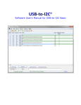
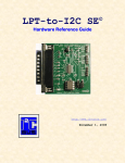
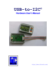
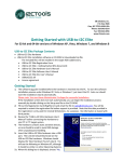
USB-to-SPI Software User’s Manual for USB-to-I2C Professional and Elite Hardware Information provided in this document is solely for use with USB-to-SPI for Professional and Elite hardware. SB Solutions, Inc. reserves the right to make changes or improvements to this document at any time without notice. We assume no liability whatsoever in the sale or use of this product, including infringement of any patent or copyright. No part of this document may be reproduced or transmitted in any form or by any means, electronic or mechanical, for any purpose, without the express written permission of SB Solutions, Inc. Microsoft and Windows are registered trademarks of Microsoft Corporation. Other brand names are trademarks or registered trademarks of their respective owners. Questions or comments regarding this document should be emailed to [email protected] 2013 SB Solutions, Inc. All rights reserved. USB-to-SPI Software User’s Manual February 2013 Page 2 USB-to-SPI Table of Contents SPI PROTOCOL ........................................................................................................................................................... 5 DATA TRANSFER ........................................................................................................................................................... 5 SPI MODE 0 .................................................................................................................................................................. 5 SPI MODE 1 .................................................................................................................................................................. 5 SPI MODE 2 .................................................................................................................................................................. 6 SPI MODE 3 .................................................................................................................................................................. 6 MAIN SCREEN............................................................................................................................................................ 7 DEVICE MENU ................................................................................................................................................................ 7 MESSAGE PANEL............................................................................................................................................................ 7 FILE MENU .....................................................................................................................................................................7 SAVE DATA .....................................................................................................................................................................7 LOAD DATA ....................................................................................................................................................................7 SLAVE SELECT ................................................................................................................................................................ 8 OPTIONS MENU ............................................................................................................................................................. 8 ENABLE 3.3V OUTPUT POWER................................................................................................................................... 8 ENABLE 5V OUTPUT POWER ...................................................................................................................................... 8 DEVICE SELECTION BY SERIAL NUMBER ................................................................................................................... 8 UPDATE USB-TO-I2C SOFTWARE ............................................................................................................................. 8 SPI CONFIGURATION .................................................................................................................................................... 8 WINDOWS MENU........................................................................................................................................................ 10 FREQUENCY INDICATOR ............................................................................................................................................ 10 STATUS BAR ................................................................................................................................................................ 10 ABOUT .......................................................................................................................................................................... 10 MEMORY DEVICES (EEPROM, RAM, FRAM)........................................................................................... 12 WRITE PAGE SIZE SELECTION.................................................................................................................................. 12 WRITE CYCLE TIME ................................................................................................................................................... 12 WREN (WRITE ENABLE)......................................................................................................................................... 12 WRDI (WRITE DISABLE) ......................................................................................................................................... 13 RDSR (READ STATUS REGISTER) ........................................................................................................................... 13 WRSR (WRITE STATUS REGISTER) ....................................................................................................................... 13 READ (READ OP-CODE) ............................................................................................................................................ 13 WRITE (WRITE OP-CODE) ....................................................................................................................................... 13 DATA GRID .................................................................................................................................................................. 13 BYTE ADDRESS (SUBADDRESS) ............................................................................................................................... 14 READ BYTE BUTTON .................................................................................................................................................. 14 READ ALL BUTTON .................................................................................................................................................... 14 WRITE BYTE BUTTON ............................................................................................................................................... 14 VERIFY BUTTON ......................................................................................................................................................... 14 FILL BUFFER................................................................................................................................................................ 15 CHECKERBOARD ......................................................................................................................................................... 15 INVERTED CHECKERBOARD ...................................................................................................................................... 15 GO TO BYTE................................................................................................................................................................. 15 USB-to-SPI Software User’s Manual Page 3 COPY BLOCK ................................................................................................................................................................ 16 EXPERT MODE....................................................................................................................................................... 17 OPEN NEW PAGE ........................................................................................................................................................ 17 OPEN DATA FILE ........................................................................................................................................................ 17 SAVE DATA .................................................................................................................................................................. 17 CLOSE EXPERT MODE ................................................................................................................................................ 18 ADD A ROW ................................................................................................................................................................. 18 DELETE A ROW ........................................................................................................................................................... 18 CLEAR THE CURRENT ROW ....................................................................................................................................... 18 CLEAR ALL THE MISO (SERIAL OUT) ROWS ......................................................................................................... 18 COPY THE CURRENT ROW......................................................................................................................................... 18 PASTE DATA ................................................................................................................................................................ 18 COMPRESS DATA ........................................................................................................................................................ 18 SEND MESSAGE ........................................................................................................................................................... 20 SEND ALL ..................................................................................................................................................................... 20 SEND SEQUENCE ......................................................................................................................................................... 20 MESSAGE EDITOR ....................................................................................................................................................... 20 MESSAGE NUMBER ..................................................................................................................................................... 21 DELAY AFTER MESSAGE ............................................................................................................................................. 21 MESSAGE DATA .......................................................................................................................................................... 21 TROUBLESHOOTING .......................................................................................................................................... 22 USB-to-SPI Software User’s Manual Page 4 SPI Protocol Data Transfer SPI is defined by both a clock polarity and phase. Here are four possible modes of operation. All of these are supported by USB-to-SPI. SPI MODE 0 Mode 0 operation is characterized by the clock (SCLK) starting at a low level. The data is sampled on the leading edge of the clock. SPI MODE 1 Mode 1 operation is characterized by the clock (SCLK) starting at a low level. The data is sampled on the falling edge of the clock. SPI MODE 2 Mode 2 operation is characterized by the clock (SCLK) starting at a high level. The data is sampled on the falling edge of the clock. SPI MODE 3 Mode 3 operation is characterized by the clock (SCLK) starting at a high level. The data is sampled on the rising edge of the clock and changes on the falling edge. USB-to-SPI Software User’s Manual Page 6 Main Screen When the USB-to-SPI program starts, a screen as shown below will be displayed on the monitor. Device Menu The device menu contains a list of SPI devices supported by the USB-to-SPI software. Selecting the device from this menu may start any of the listed devices. You can have any combination of devices open at one time. Switching between active devices may be accomplished via the Window menu on the main toolbar. USB Hardware Indicator Slave Select Output Power Options Menu Device Menu Indicators Message Panel SPI Frequency SPI Mode Indicator Message Panel The main screen has a panel that displays messages from the program. It will indicate if the SPI transmission was successful or if a problem was encountered. File Menu Upon starting the USB-to-SPI software, the File menu contains the Exit and Close commands. When a device has been selected from the Device Menu, it is possible that the File Menu will also display device specific commands such as Save As and Load. In User Device mode, previously created device files may conveniently be loaded. Save Data Many devices contain the menu item 'Save Data' under the File menu. The data may be recalled by selecting the Load Data item under the File Menu. Load Data After data has been stored using the 'Save Data' item in the File menu, it can be recalled by selecting the Load Data item. USB-to-SPI Software User’s Manual Page 7 Slave Select This feature is only available in the Elite hardware. The Elite hardware has the capability to control three slave select outputs. By default, Slave Select 0 (SSN0) is used. Options Menu The options menu allows you to change the SPI frequency, the 3.3V and 5V power outputs are also controlled from this menu. If you have multiple USB-to-I2C hardware units connected to your PC, you can select which device you would like to communicate with. Enable 3.3V Output Power By selecting the 3.3V Output Power menu item, the USB-to-I2C hardware will supply power to your target system. There is no need to enable this output unless you would like to power to your target system from this power source. When enabled, there will be a green dot beside the menu item and the status bar at the bottom of the application will have a 3.3V On indicator shown in green. Enable 5V Output Power By selecting the 5V Output Power menu item, the USB-to-I2C hardware will supply power to your target system. There is no need to enable this output unless you would like to power to your target system from this power source. When enabled, there will be a green dot beside the menu item and the status bar at the bottom of the application will have a 5V On indicator shown in green. Device Selection by Serial Number A list of USB-to-I2C hardware devices currently connected to the PC is shown at the bottom of the Options menu. If more than one device is connected, you will be able to select the device to control by selecting it from the menu. Update USB-to-I2C Software The application will check if a newer version of USB-to-SPI software is available. Your PC will need to be connected to the internet for this feature to function. SPI Configuration When SPI Configuration is selected from the Options menu, a screen will be shown allowing you to change the frequency, the data order, and the SPI mode. The configuration will be sent to the device immediately clicking the OK button. USB-to-SPI Software User’s Manual Page 8 The configuration screen is different for the Elite and Professional hardware. The main difference is the Elite hardware allows several different SPI clock speeds between 5k and 30 MB bits/second while the Professional software limits the clock speeds to 125k, 250k, 1M, or 4M bits/second. Here’s the configuration for the Professional software. USB-to-SPI Software User’s Manual Page 9 Windows Menu The Windows Menu contains screen commands such as cascade, tile, arrange all icons, and minimize all. If there are devices active in the program, you will find them listed in this menu. When multiple device types are open, it is easy to move between the device types by clicking on the desired item in this menu. Frequency Indicator The frequency at which the hardware is sending SPI messages over the bus is shown in this box on the main screen. You can change the frequency by selecting the SPI Configuration item in the Options menu. Status Bar The status bar at the bottom of the USB-to-SPI application provides the following information: 1. Message Panel – will update after each SPI message has been sent. It also gives a visual indicator when messages are being sent. The image below shows a progress bar when an eeprom is being programmed. After the message has been sent, another status update is displayed, as shown here: 2. Hardware Status - the second panel in the status bar shows if the software has found the USB-to-I2C hardware. When the hardware is not connected, it will display “Hardware Not Detected” in red. When the hardware is connected, it will display “Hardware Detected”, as shown above. 3. Output power indicators – show when the 3.3V and 5V power outputs on the hardware are active. When red, the outputs are disabled, while they will change to green when enabled. The outputs can be enabled/disabled using the Options menu, or by double-clicking the status bar. 4. SPI Frequency indicator – shows the SPI clock frequency. The frequency can be changed using the Options menu item, or by double-clicking the status bar. Mode output – shows the SPI mode currently in use. The mode can be changed using the Options menu or by double-clicking the status bar. About The About menu selection brings up a dialog box containing information about the software. If the hardware is plugged into the PC, the firmware revision will be displayed. In this example, the firmware revision is 2.3. You can upgrade the firmware in the USB-to-I2C Elite and Professional hardware (depending upon the hardware and firmware version). See the Hardware User’s Manual for firmware upgrade instructions. USB-to-SPI Software User’s Manual Page 10 USB-to-SPI Software User’s Manual Page 11 Memory Devices (EEPROM, RAM, FRAM) Upon starting any memory type device, you will see a screen similar to the one shown below. Write Page Size Selection The Page Write Size defines the number of bytes that may be written in a single erase/write programming cycle. Smaller devices generally use 8 or 16-byte pages while larger devices use up to 128 bytes per page. Check the device datasheet to find the appropriate page write size for the device you are programming. If you do not know the page size, use a small page size such as 8 bytes. A smaller page size will require a longer total programming time for a device. Write Cycle Time Programming software must allow a certain period of time to elapse after writing a block of data to an EEPROM. This time is device dependent but is normally between 5ms and 40ms. The USB-to-SPI software does not check the Status Register before sending the next page of data so it is important to use an appropriate Write time. WREN (Write Enable) The WREN command must be sent to an eeprom before any write operations are performed. The op-code can be changed USB-to-SPI Software User’s Manual Page 12 by the user and it can be sent to the device by pressing the Write button located next to the WREN edit box. WRDI (Write Disable) Sending the WRDI command to an eeprom will disable all write activities. Pressing the Write button located beside the WRDI op-code will send the single WRDI byte to the EEPROM. RDSR (Read Status Register) The RDSR command allows the SPI master to read the contents of the Status register. Please see the particular device datasheet you are communicating with to determine what the contents of the Status Register mean. The op-code for RDSR can be changed by the user. Pressing the Read button located beside the RDSR op-code will return the contents of the register. WRSR (Write Status Register) Writing to the Status Register allows the user to modify the contents of this register. Please see the device datasheet to determine what the Status Register contents mean. Read (Read Op-code) The Read op-code is used when reading data from the eeprom. Write (Write Op-code) The Write op-code is used when writing data to the eeprom. Data Grid The data grid consists of rows and columns. Each cell within the grid contains a two digit hexadecimal number. Each cell corresponds to a physical byte location within the memory device. For example, in the diagram below, cell 0x21 is highlighted (row 2, column 1). This translates to address 33 (decimal) in the device. The program calculates the physical address for you and displays it at the left side of the screen in the box labeled ‘Word Address’ or ‘Subaddress’. USB-to-SPI Software User’s Manual Page 13 Byte Address (Subaddress) The byte address (sometimes called subaddress or word address) is a pointer to a register or memory location within the SPI device. To access this location, the software will send out the device SPI address, followed by this byte address, followed by the read or write data. The program displays the byte address of the active cell of the memory grid in hexadecimal notation. Read Byte Button Pressing the 'Read Byte' button initiates a read from the SPI device. The program begins the transmission by sending the Read Op-code, followed by the selected byte address, and finally a read of a single data byte. The result of each byte read is immediately entered in the appropriate cell in the grid. Read All Button Pressing the 'Read All' button initiates a read of the entire device. The program begins the transmission by sending the Read Op-code, then the byte address 0x00. The data is then read from the device. Write Byte Button Pressing the 'Write Byte' button initiates a Write to the SPI device. The program begins the transmission by sending the WREN Op-code. The CS line is then de-asserted after sending the WREN Op-code. The CS line is again asserted after a short delay. The Write Op-code is transmitted, followed by the byte subaddress of the currently active cell in the grid. The selected data byte is then sent. Pressing the 'Write All' button initiates a Write to the SPI device. The program begins the transmission by writing the byte address 0x00 to the device and sequentially writes the entire device. For a RAM type device, the data is sent in one long message. In the case of an EEPROM, the software will send one page of data (usually 8 bytes but check the datasheet for the particular device you are addressing) followed by a STOP condition. Following the STOP condition, the program waits a length of time, determined by the Erase/Write cycle time of the device (again check the datasheet for the device you are programming), before writing another page to the device. In addition to pressing the 'Write All' button, you may press the <Alt> and <w> keys simultaneously to achieve the same results. After the completion of the write cycle, USB-to-SPI will read the entire device to verify that the contents of the device match the data that was sent. An error message will be displayed if the data read from the device does not match the data in the on-screen buffer. Verify Button Pressing the ‘Verify’ button initiates a read of the entire EEPROM. After reading the contents of the EEPROM, USB-to-SPI will compare the contents with the values in the grid. An error will be flagged if the contents of the EEPROM do not match the contents of the USB-to-SPI on-screen grid. USB-to-SPI Software User’s Manual Page 14 Fill Buffer The grid will be filled with the two digit hexadecimal number found in the ‘Fill with’ edit box when the Fill Buffer button is pressed. The fill can be constrained to the addresses found in the ‘Fill from’ to the ‘Fill to’ edit boxes. No information will be sent over the SPI bus. Checkerboard The grid will be filled an alternating ‘1’ and ‘0’ pattern when this is chosen from the Fill with Checkerboard selection is made on the Edit menu. Inverted Checkerboard The grid will be filled an alternating ‘0’ and ‘1’ pattern when this is chosen from the Fill with Inverted Checkerboard selection is made on the Edit menu. Go To Byte... When the Go To Byte menu selection is made from the Edit menu, a dialog box is displayed where a hex or decimal address may be entered. When the OK button is pressed the grid location with the desired address is shown. This is useful when you don’t want to scroll through to find a specific data location. USB-to-SPI Software User’s Manual Page 15 Copy Block It is possible to copy a block of data from one on-screen buffer area to another using the Copy Block function. Simply define the data to be copied using the ‘Copy From’ edit boxes and then enter the address where the data is to be copied to. The ending address is calculated automatically by the software and is not editable by the user. Pressing the Copy Block button starts the copying process. USB-to-SPI Software User’s Manual Page 16 Expert Mode The figure below shows the Expert Mode screen. Each SPI message is shown as two rows. The first row in the message is the MOSI, or Master Out – Slave In. The second is the MISO, or Master In – Slave Out. The MOSI row is sent out by the Expert Mode and the slave responds with data which is then displayed in the MISO row. Open New Page Pressing this button opens a new blank page. There will be 32 empty rows (messages). Selecting ‘New’ from the ‘File’ menu while the Expert Mode is active will perform the same function. Open Data File A previously saved data file can be recalled by pressing the Open Data File button or by selecting Open from the File menu while the Expert Mode is active. A dialog box will be displayed allowing the user to navigate to the appropriate directory. Save Data The current data will be saved when this button is pressed. The user specifies the name and location of the file in a dialog box that is displayed after the button is pressed. A dialog box will be displayed which allows the user to navigate to the appropriate directory. USB-to-SPI Software User’s Manual Page 17 The user can also perform the same function by selecting Save from the File menu while the Expert Mode screen is active. Close Expert Mode The Expert Mode screen is closed but USB-to-SPI will not be terminated. Add a Row Inserts a new (blank) message at the current row. You can also use the Ctrl+Ins keyboard shortcut to insert a new row. The interface is limited to 64 bytes. Delete a Row Deletes the current row (current message). You can also use the Ctrl+Del keyboard shortcut to delete the current row. Clear the current row The current row will be cleared. The row will not be deleted but will appear blank. You can also use the Shift+Del keyboard shortcut to clear the current row. Clear all the MISO (Serial Out) rows All the data in the MISO (serial out) rows will be cleared. Copy the Current Row The current row (message) will be copied. Use the Paste command to paste it to a different row. You can also use the Ctrl+C keyboard shortcut to copy the current row. Paste Data Previously copied data will be pasted into the current row (message). You can also use the Ctrl+V keyboard shortcut to paste the clipboard into the current row. Compress Data All blank rows will be eliminated from the display. Here is an example of a display before compress: USB-to-SPI Software User’s Manual Page 18 And here is the same screen after the compress: USB-to-SPI Software User’s Manual Page 19 It is not a requirement to perform a compress but it does speed up the message transfer process since the application does not need to evaluate blank rows to see if there is data to be sent. Send Message The current message will be sent when this button is pressed. The current message number is shown below the Send Message button. To change the active message, single-click on a new row. You can select either the MOSI or MISO row to change the active message. Send All All the valid messages on the screen will be sent in order of the row number. The action will be performed one time. A message is valid if there is a minimum of an address within the message. Since the program tests for a valid message on each line within the message grid before sending the message, it is recommended (not required) to compress the data (see Compress Data above) to speed up the transfer. Send Sequence A sequence of messages will be sent when the Send Sequence button is pressed. The sequence editor is invoked by double-clicking on the sequence display. The sequence length can be up to 64 messages in length. The sequencer is limited to using messages 1 through 99. The Sequence Editor is shown above. Message Editor The SPI message cannot be edited directly in the Expert mode screen. Instead, an Expert Mode Editor is brought up either by double-clicking on a message or when the user USB-to-SPI Software User’s Manual Page 20 attempts to type directly into one of the rows (messages) in the Expert Mode screen. Message Number The message being edited is shown at the top of the message editor screen. Delay after message A delay, measured in milliseconds, can be inserted after a message. Message Data The Message Data area contains the location where the user can enter up to 128 data bytes in hexadecimal format. Blank data bytes will be ignored. USB-to-SPI Software User’s Manual Page 21 TROUBLESHOOTING If you have problems with the software installation, ensure that you have Admin Privileges. If the installer application doesn’t launch when the CD-ROM is inserted, then manually browse the CD-ROM and find the Setup.exe file in the root directory of the CD. Double-click on the Setup.exe file to start the installation process. The USB-to-I2C software will not function on Windows 95, Windows 98 (First edition), or NT systems; therefore, installation will not proceed if you attempt to install the software on these Operating Systems. USB-to-I2C hardware monitors the communications on the I2C bus for proper operation of connected peripherals; any errors on the bus are detected and reported by the software. Bus communication is stopped if errors are detected and can be resumed when the (hardware) problem is corrected and the transmission retried. Keep the original USB-to-I2C installation files in the event the software needs to be re-installed. Future USB-to-I2C updates from our website may require a previous installation from the original media. The USB-to-SPI software requires that Microsoft GDI+ is installed on your PC. It is normally installed by Windows, however, if you receive an error message indicating that the GDI dll is missing, you can download it from the Microsoft website: Microsoft GDI+ download Check for new versions of the software at http://www.i2ctools.com/downloads.html The firmware for the Elite and Professional hardware can be upgraded by the user, if the firmware loaded on the Elite hardware is version 2.0 or later, and the Professional hardware is v3 or later. We will also upgrade the firmware for you if you have an earlier revision. The hardware will need to be returned to us for version 1.x. Please visit the i2ctools website to find the latest firmware information. If all else fails, email a description of the problem you are having to us at [email protected]. Note that all technical support requests must begin with an email to this email address. We are interested in receiving feedback from our customers. Is there is a feature that should be added to make this tool better? Please send your requests and comments to [email protected]. USB-to-SPI Software User’s Manual Page 22