1
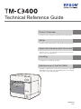
Technical Reference Guide
Product Overview
Describes features and general specifications for the product.
Setup
Describes setup and installation of the product and peripherals.
Application Development Information
Describes how to control the printer and necessary information
when you develop applications.
Handling
Describes how to handle the product.
Maintenance of the TM-C3400
Describes to administrator for necessary information to administer
TM-C3400 in the system such as distributing driver or installing
new printer or replacing the printer.
M00008308
Rev.I
Cautions
• No part of this document may be reproduced, stored in a retrieval system, or transmitted in any form
or by any means, electronic, mechanical, photocopying, recording, or otherwise, without the prior
written permission of Seiko Epson Corporation.
• The contents of this document are subject to change without notice. Please contact us for the latest
information.
• While every precaution has taken in the preparation of this document, Seiko Epson Corporation
assumes no responsibility for errors or omissions.
• Neither is any liability assumed for damages resulting from the use of the information contained
herein.
• Neither Seiko Epson Corporation nor its affiliates shall be liable to the purchaser of this product or third
parties for damages, losses, costs, or expenses incurred by the purchaser or third parties as a result of:
accident, misuse, or abuse of this product or unauthorized modifications, repairs, or alterations to this
product, or (excluding the U.S.) failure to strictly comply with Seiko Epson Corporation’s operating
and maintenance instructions.
• Seiko Epson Corporation shall not be liable against any damages or problems arising from the use of
any options or any consumable products other than those designated as Original EPSON Products or
EPSON Approved Products by Seiko Epson Corporation.
Trademarks
Microsoft®, Windows®, Windows Vista®, Windows Server®, Win32®, Visual Basic®, Visual C++®, and
Visual C#® are registered trademarks of Microsoft Corporation.
EPSON® is registered trademarks of Seiko Epson Corporation in Japan and other countries./regions.
Copyright
The Ethernet interface model of this product includes software developed by the University of California, Berkeley, and its contributors.
Copyright © 2009-2012 Seiko Epson Corporation. All rights reserved.
2
For Safety
Key to Symbols
The symbols in this manual are identified by their level of importance, as defined below. Read
the following carefully before handling the product.
You must follow warnings carefully to avoid serious bodily injury.
WARNING
CAUTION
Provides information that must be observed to prevent damage to the equipment or loss of
data.
• Possibility of sustaining physical injuries.
• Possibility of causing physical damage.
• Possibility of causing information loss.
Provides information that must be observed to avoid damage to your equipment or a
malfunction.
Provides important information and useful tips.
3
Warnings
WARNING
4
• To avoid risk of electric shock, do not set up this product or handle cables during
a thunderstorm
• Be sure to use the power cable complied with safety standards with a PE (power
earth) terminal on the plug, and make sure to ground the product before use.
Ignoring this may result in severe shock.
• Never insert or disconnect the power plug with wet hands.
Doing so may result in severe shock.
• Handle the power cable with care.
Improper handling may lead to fire or electric shock.
∗ Do not modify or attempt to repair the cable.
∗ Do not place any heavy object on top of the cable.
∗ Avoid excessive bending, twisting, and pulling.
∗ Do not place the cable near heating equipment.
∗ Check that the plug is clean before plugging it in.
∗ Be sure to push the plug all the way in.
• Be sure to use the specified power source.
Connection to an improper power source may cause fire or shock.
• Do not place multiple loads on the power outlet.
Overloading the outlet may lead to fire.
• Shut down your equipment immediately if it produces smoke, a strange odor, or
unusual noise.
Continued use may lead to fire. Immediately unplug the equipment and contact your
dealer or a Seiko Epson service center for advice.
• Never attempt to repair this product yourself.
Improper repair work can be dangerous.
• Never disassemble or modify this product.
Tampering with this product may result in injury or fire.
• Do not allow foreign matter to fall into the equipment.
Penetration by foreign objects may lead to fire.
• If water or other liquid spills into this equipment, do not continue to use it.
Continued use may lead to fire. Unplug the power cord immediately and contact your
dealer or a Seiko Epson service center for advice.
• If you open the DIP switch cover, be sure to close the cover and tighten the screw
after adjusting the DIP switch.
Using this product with the cover open may cause fire or electric shock.
Cautions
CAUTION
• Do not connect cables in ways other than those mentioned in this manual.
Different connections may cause equipment damage or fire.
• Do not connect cables in ways other than those mentioned in this manual.
Different connections may cause equipment damage or fire.
• Be sure to set this equipment on a firm, stable, horizontal surface.
The product may break or cause injury if it falls.
• Do not use this product in locations subject to high humidity or dust levels.
Excessive humidity and dust may cause equipment damage or fire.
• Do not place heavy objects on top of this product. Never stand or lean on this
product.
Equipment may fall or collapse, causing breakage and possible injury.
• Do not use aerosol sprayers containing flammable gas inside or around this
product.
Doing so may cause fire.
• Do not use this product in the presence of silicon gas (silicon adhesive, silicon
oil, silicon powder, etc.) including siloxane and of malignant gas (nitric acid,
hydrosulfuric, ammonia, chlorine, etc.).
Doing so may cause a product failure in a short time.
• To ensure safety, unplug this product before leaving it unused for an extended
period.
• Do not remove the ink cartridge during transportation of the printer.
Restriction of Use
When this product is used for applications requiring high reliability/safety such as
transportation devices related to aviation, rail, marine, automotive etc.; disaster prevention
devices; various safety devices etc.; or functional/precision devices etc., you should use this
product only after giving consideration to including fail-safes and redundancies into your
design to maintain safety and total system reliability.
5
About this Manual
Aim of the Manual
This manual was created to provide information on development, design, and installation of
POS systems and development and design of printer applications for developers.
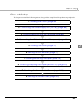
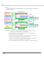
Manual Content
The manual is made up of the following sections:
6
Chapter 1
Product Overview
Chapter 2
Setup
Chapter 3
Application Development Information
Chapter 4
Handling
Chapter 5
Maintenance of the TM-C3400
Contents
■ For Safety .............................................................................................................................. 3
Key to Symbols ........................................................................................................................................3
Warnings ..................................................................................................................................................4
Cautions ..................................................................................................................................................5
■ Restriction of Use .................................................................................................................. 5
■ About this Manual ................................................................................................................ 6
Aim of the Manual .................................................................................................................................6
Manual Content .....................................................................................................................................6
■ Contents................................................................................................................................ 7
Product Overview ........................................................................ 11
■ Features............................................................................................................................... 11
■ Product Configuration........................................................................................................ 13
Interface ................................................................................................................................................13
Color ......................................................................................................................................................13
Accessories ...........................................................................................................................................13
■ Parts Name and Function .................................................................................................. 14
Power Switch .........................................................................................................................................16
Power Switch Cover .............................................................................................................................16
Button.....................................................................................................................................................17
LED..........................................................................................................................................................17
Connectors ...........................................................................................................................................18
Paper ejection tray ..............................................................................................................................18
■ Status/Error Indications ...................................................................................................... 19
■ Post-Printing Verification Settings...................................................................................... 21
When an Unrecoverable Missing Dot Occurs ...................................................................................24
■ Software .............................................................................................................................. 26
■ Product Specifications ....................................................................................................... 27
Hardware Requirements......................................................................................................................29
Printing Specifications ..........................................................................................................................30
Paper Specifications ............................................................................................................................31
Print Area and Cutting Position ...........................................................................................................45
Paper Ejection Tray...............................................................................................................................53
Ink Cartridge .........................................................................................................................................53
Electrical Characteristics .....................................................................................................................54
Reliability................................................................................................................................................55
Environmental Conditions....................................................................................................................56
External Dimensions..............................................................................................................................57
Power Supply Unit (PS-180) ..................................................................................................................58
■ Restrictions .......................................................................................................................... 59
7
Setup .............................................................................................61
■ When You Use This Printer for the First Time...................................................................... 61
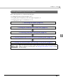
■ Flow of Setup ...................................................................................................................... 63
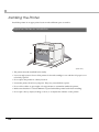
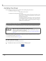
■ Installing the Printer............................................................................................................ 64
Important Notes on Installation .......................................................................................................... 64
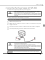
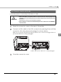
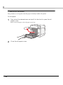
■ Connecting the Power Supply Unit (PS-180).................................................................... 65
Connecting the AC Cable ................................................................................................................. 65
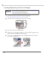
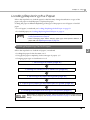
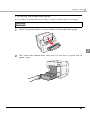
■ Loading/Replacing the Ink Cartridge.............................................................................. 66
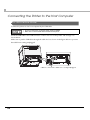
■ Connecting the Printer to the Host Computer ................................................................. 68
For USB Interface Model...................................................................................................................... 68
For Ethernet Interface Model ............................................................................................................. 69
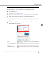
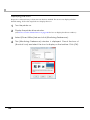
■ Installing the Driver ............................................................................................................ 70
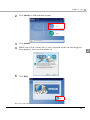
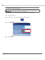
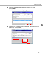
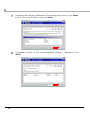
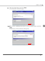
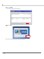
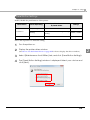
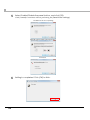
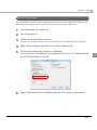
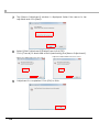
Installation using Easy setup ............................................................................................................... 70
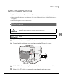
■ Setting the DIP Switches..................................................................................................... 77
Setting Procedure ................................................................................................................................ 77
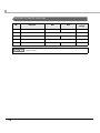
Function of the DIP Switches .............................................................................................................. 78
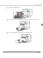
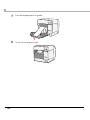
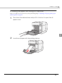
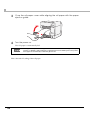
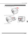
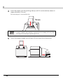
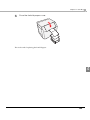
■ Loading/Replacing the Paper .......................................................................................... 79
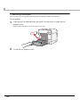
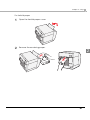
Loading/Replacing the Roll Paper .................................................................................................... 79
Loading/Replacing Fanfold Paper .................................................................................................... 89
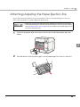
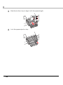
■ Attaching/Adjusting the Paper Ejection Tray .................................................................. 99
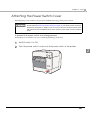
■ Attaching the Power Switch Cover ................................................................................. 101
■ Setting the Printer Driver .................................................................................................. 103
Post-Printing Verification Settings...................................................................................................... 103
Notification Settings ........................................................................................................................... 109
Media Loading Settings .................................................................................................................... 111
Media Position Detection.................................................................................................................. 113
Panel Button Settings ......................................................................................................................... 115
Sensor Adjustment ............................................................................................................................. 117
Setting EPSON Status Monitor 3 ........................................................................................................ 119
Setting the Post-Printing Movements ............................................................................................... 125
Application Development Information....................................131
■ Overview........................................................................................................................... 131
■ Printer Driver ..................................................................................................................... 131
■ Sample Program .............................................................................................................. 132
■ EpsonNet SDK ................................................................................................................... 134
Environmental Setting for EpsonNet SDK ......................................................................................... 134
■ Utilities and Manuals ........................................................................................................ 136
Download ........................................................................................................................................... 138
8
■ Printer Driver and Utility Function List .............................................................................. 139
Network Setting of the Printer ...........................................................................................................140
Setting the Printer ...............................................................................................................................144
Acquiring Printer Status......................................................................................................................146
■ Application Specification to Develop ............................................................................ 147
Character Size to Print .......................................................................................................................147
Print Barcode / 2D Symbol Data on the Graphic Data .................................................................148
When Extremely High Reliability and Safety are Required ............................................................148
Handling ..................................................................................... 149
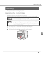
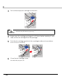
■ Replacing the Ink Cartridge ........................................................................................... 149
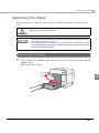
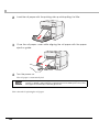
■ Replacing the Paper ........................................................................................................ 151
Replacing the Roll Paper...................................................................................................................151
Replacing the Fanfold Paper............................................................................................................153
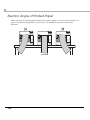
■ Ejection Angle of Printed Paper...................................................................................... 156
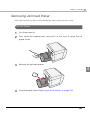
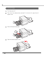
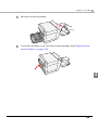
■ Removing Jammed Paper .............................................................................................. 157
For Roll Paper ......................................................................................................................................157
For Fanfold Paper ...............................................................................................................................158
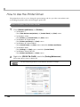
■ How to Use the Printer Driver ........................................................................................... 160
How to Display the Printer Driver.......................................................................................................160
Registering User Defined Media .......................................................................................................161
Favorite Setting ...................................................................................................................................162
Information for User Definition ...........................................................................................................165
Barcode Printing .................................................................................................................................166
2D Symbol Font Settings.....................................................................................................................179
Barcode and 2D Symbol Font Printing on .NET Environment.........................................................186
Functions of the Printer Driver ...........................................................................................................188
■ Uninstalling the Printer Driver........................................................................................... 195
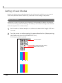
■ Setting Check Modes ...................................................................................................... 198
Self-test Mode .....................................................................................................................................198
Status Sheet Printing (Ethernet interface model only) ...................................................................200
■ Head Cleaning ................................................................................................................. 201
Manual Head Cleaning.....................................................................................................................201
Manual Head Cleaning during printing ..........................................................................................201
Nozzle Check ......................................................................................................................................202
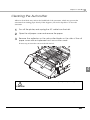
■ Cleaning the Autocutter.................................................................................................. 203
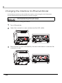
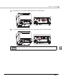
■ Changing the Interface for Ethernet Model .................................................................. 204
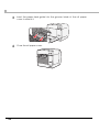
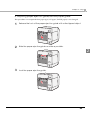
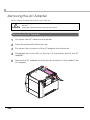
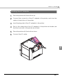
■ Removing the AC Adapter.............................................................................................. 206
Removing the AC Adapter ...............................................................................................................206
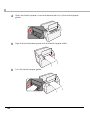
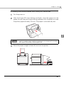
Installing the AC Adapter ..................................................................................................................207
■ Preparing for Transport..................................................................................................... 208
9
■ Troubleshooting ................................................................................................................ 208
Lighting and Flashing the Error LED .................................................................................................. 208
Maintenance of the TM-C3400.................................................209
■ Necessary Information for an Administrator of the Printer ...........................................210
Printer Driver Functions ...................................................................................................................... 210
Destination for the Printer Driver Setting.......................................................................................... 211
Printer Setting ..................................................................................................................................... 212
Installing Multiple Printer Drivers in One Client Computer ............................................................ 214
Using One Network Printer with Multiple Client Computers ......................................................... 218
Upgrading the Printer Driver ............................................................................................................. 218
Printer Driver cannot be Installed (Windows 2000) ........................................................................ 219
Printer Driver is Already Installed (Windows 2000) .......................................................................... 219
■ Distributing the Printer Driver and Setting the Printer.....................................................220
Utility .................................................................................................................................................... 220
Preparation for the Administrator .................................................................................................... 221
Setup Procedure................................................................................................................................ 225
Examples of Usage ............................................................................................................................ 227
■ Maintenance ....................................................................................................................236
Adding a Client Computer (for the Ethernet Interface Model) ................................................... 236
Adding a Printer................................................................................................................................. 237
Adding a paper type/changing the print setting ......................................................................... 238
Replacing the Printer......................................................................................................................... 238
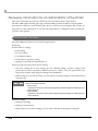
■ Managing the Printer .......................................................................................................241
Monitoring the Network Printer ........................................................................................................ 241
■ For Inquiries .......................................................................................................................242
10
Chapter 1 Product Overview
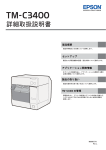
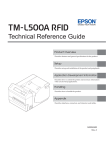
Product Overview
This chapter describes features and specifications of the product.
Features
The TM-C3400 is a 3-color ink jet printer that offers high speed easy operability and high
reliability required for on-demand label printing.
Printing
1
• High-speed printing
∗ 92 mm/s (printing width 56 mm, 360 dpi × 180 dpi, bi-directional printing)
∗ 47 mm/s (printing width 56 mm, 360 dpi × 360 dpi, bi-directional printing)
The print speed is different depending on the resolution and the printing width.
• Color printing
∗ CMY 3-color printing
∗ Print resolution: Plain Media, Plain Media Label 360 dpi × 180 dpi, 360 dpi × 360 dpi
: Others 360 dpi × 360 dpi, 720 dpi × 360 dpi
dpi: dots per 25.4 mm (dots per inch)
∗ Each color has 4 gradations
• Supports printing on various types of paper
∗ Roll paper, Fan-fold paper
∗ Receipt, Black Mark Receipt, Full-page Label, Die-cut Label, Black Mark Die-cut Label
(Detects positions of black marks and gaps between labels)
∗ Plain Media, Plain Media Label, Fine Media, PET Film, Synthetic Media Label
∗ Wrist Band
• System to prevent ink from smearing out of the printable area such as on the backing paper of
Die-cut Label.
• System to prevent missing read or missing color caused by missing dots.
Handling
• Replacing the roll paper and the ink cartridge can be done only by operation in the front.
• Easy drop-in paper loading
• Multiple printed sheets can be stored in the paper ejection tray. The paper ejection tray cannot
store multiple sheets of roll paper.
11
Reliability
• Pigment ink for excellent light-fastness and water-resistance.
• High reliability system to prevent missing dots with auto nozzle check system installed.
Software
• Windows® printer driver is available.
• The printer driver has the built-in barcode font, and available from .NET application.
• Reprint function allows printing to the page that was not printed after solving paper jam error
or an error of paper out.
• The printer status can be obtained in network environment by EpsonNet SDK.
(SDK is provided as API to make original application for obtained printer status.)
• Dedicated sample program using EpsonNet SDK (program language: VB.NET, C + +, VB6.0,
C#) is prepared.
Others
• Detects black marks and gaps between labels (for Die-cut Label)
• Auto-cutter
• Buzzer
12
Chapter 1 Product Overview
Product Configuration
Interface
• USB interface model (USB 2.0 high speed)
• Ethernet interface model (100 Base-TX/10 Base-T)
Color
White (ENN8.5)
1
Accessories
Unpacking
• Roll paper (for checking initial movement)
• Ink cartridge (Model number: SJIC15P)
• Paper ejection tray
• Power switch cover
• Paper feed guide (for fanfold paper: attached on the rear of the fanfold paper cover)
• AC Adapter (Model: PS-180)
• AC cable
• USB cable (USB interface model only)
• Instruction sheet
• User’s Manuals (for printer and AC adapter)
• The AC adapter is embedded in the printer.
• The AC cable may not be included with the printer.
Printer Drivers and utilities are not included with this product.
Download them from the home page of Seiko Epson Corporation.
13
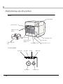
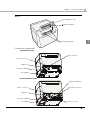
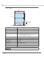
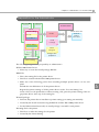
Parts Name and Function
Front
Control panel
Release lever
Paper ejection
guide
Paper ejection
table
Ink cartridge cover
Paper ejection
guide lock
Paper ejection
tray
Power switch
Roll paper cover
Control panel
Power LED
Error LED
Ink LED
CUT button
14
Paper LED
FEED button
Power switch cover
Chapter 1 Product Overview
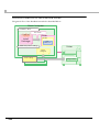
Back
Fanfold paper cover
Paper feed guide
1
Fanfold paper guide
Connector (lower rear)
USB Interface Model
USB connector
Power connector
Cable hook
Inlet (AC Adapter)
AC Adapter
Ethernet Interface Model
Status sheet button
Power connector
Ethernet Connector
Cable hook
Inlet (AC Adapter)
AC Adapter
Connector cover
15
Power Switch
Before turning on the printer, be sure to check that the AC adapter is connected to
the power supply.
CAUTION
• When DIP switch 1 is OFF, the power is turned on after the POWER button has been pressed
while the power is OFF.
• When DIP switch 1 is OFF, the power is turned off after the POWER button has been pressed
for approximately 3 seconds while the power is ON.
• When DIP switch 1 is ON, the printer settings are reset after the POWER button has been
pressed for approximately 3 seconds.
See "Setting the DIP Switches" on page 77 for DIP switch setting.
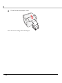
Power Switch Cover
Attaching the power switch cover prevents accidental pressing of the power switch.
∗ To prevent the power switch from being pressed:
Attach the power switch cover as it is (without punching a hole in it).
∗ To prevent the power switch from being pressed unless a long, thin object is pressed into a hole in the
power switch cover:
Attach the power switch cover after punching a hole in it.
For details about attaching the power switch cover, see "Attaching the Power Switch
Cover" on page 101.
Be sure to change the DIP switch setting when you want to attach the power switch cover
without punching a hole in it. (See "Setting the DIP Switches" on page 77.)
Make sure to pull out the AC cable if the printer is damaged when attaching the
power switch cover. Using it as it is may cause a fire.
WARNING
16
Chapter 1 Product Overview
Button
FEED button
• Feeds the paper continuously when media position detection is set to “No Detection”.
∗ The paper is fed by 15 mm if FEED button is pressed once.
∗ If the FEED button is held down, the paper is continuously fed until the button is released.
(6 seconds at a maximum)
• Feeds the paper to the print starting position when media position detection is set to “Detects
Black Marks” or “Detects Margins Between Labels”.
CUT button
• Feeds the paper to the first auto cut position on the next page and cuts the paper automatically
when media position detection is set to “No Detection”.
• Feeds the paper to the autocut position by detecting the gap between the black marks or labels
and cuts the paper automatically when media position detection is set to “Detects Black
Marks” or “Detects Margins Between Labels”.
Status sheet button (Ethernet interface model only)
Prints status sheet.
It is recommended to use Plain Media Roll paper with the width of 108 mm for printing the
status sheet.
• The media position detection setting is set on [Maintenance And Utilities] tab on the
printer driver.
• See "Status Sheet Printing (Ethernet interface model only)" on page 200 for the status
sheet.
LED
POWER (power) LED: Green
• Lights when the power is on.
• Lights off when the power is off.
• Flashes when the printer is operating (initializing, charging ink, head cleaning, Closing roll
paper cover, or printing) or in an error state.
ERROR (error) LED: Red
• Lights or flashes when the printer is offline.
• Lights off when the printer is normal operation (online).
17
1
INK (ink) LED: Red
• Flashes when the ink is low or waste ink in the ink cartridge is nearly full.
• Lights when it is time to replace the ink cartridge, when the ink cartridge is not installed or is
not correctly installed, and when waste ink in the ink cartridge is full.
• Lights off when ink in the ink cartridge is adequate.
PAPER (paper out) LED: Red
• Lights when the paper is not installed or is not correctly installed.
• Lights off when the paper is correctly installed.
• The INK LED does not flash even if the ink is low when the “LED Notification Setting at
Ink Low” is set not to appear on [Notification Settings] on [Maintenance And Utilities] tab
of the printer driver.
• The printer status is also displayed with combination of lighting and flashing of LED’s.
See "Status/Error Indications" on page 19 for details.
Connectors
All cables are connected to the connector on the lower rear of the printer.
• Power supply connector: Connects cable of the AC adapter. The AC adapter itself is installed
at factory before shipping.
• USB Connector:
Connects the printer with the host computer via interface.
• Inlet (AC Adapter):
Connects the AC cable.
For details how to connect the interface and power supply connector, see "Connecting the
Printer to the Host Computer" on page 68.
Paper ejection tray
Installing the paper ejection tray enables you to accumulate printed paper temporarily in it.
• For how to attach the paper ejection tray, see "Attaching/Adjusting the Paper Ejection
Tray" on page 99.
• For maximum capacity for ejected paper of the paper ejection tray, see "Paper Ejection
Tray" on page 53.
Paper may fall from the paper ejection tray due to a curl or the length of the paper.
18
Chapter 1 Product Overview
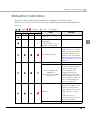
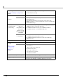
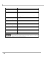
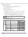
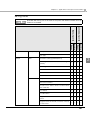
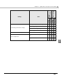
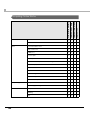
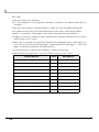
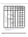
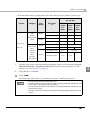
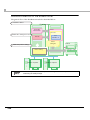
Status/Error Indications
The printer status is displayed with combination of lighting and flashing of LEDs.
When an error occurs, you can find out the cause and the remedy from the LED indication for
the error.
/
: Lights
/
: Flashes
: Off
—:
LED
Power
Error
Ink
Paper
—
—
—
No change
Status
Remedy
Power on
—
Powering off
—
—
—
Charging ink
1
—
Closing roll paper cover
Saving or printing data
AID temperature error
The ambient temperature
may be too low or too high.
Make sure that the ambient
temperature between 10°C
and 35°C, turn off the printer
and then turn it back on. (See
"Environmental Conditions" on
page 56.)
Maintenance requirement
The printer needs repair.
Unrecoverable nozzle
clogging error
(Missing Dot Acceptable
Print Mode)
This condition occurs when
turning on the printer after a
fatal error resulting from
unrecoverable nozzle
clogging. In this mode,
printing is performed even
with a missing dot. The printer
needs repair. (See "When an
Unrecoverable Missing Dot
Occurs" on page 24.)
1. Turn the power off.
Fatal error
2. Open the roll paper cover
and remove the jammed
paper if any. (See "Removing
Jammed Paper" on page
157.)
3. Turn the power on.
If the same error persists, the
printer needs repair.
Cutter error
—
19
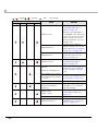
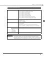
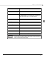
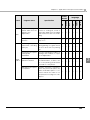
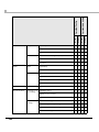
/
: Lights
/
: Flashes
: Off
LED
Power
Error
Ink
—:
No change
Status
Paper
Remedy
Set specified papers. (See
"Loading/Replacing the
Paper" on page 79.)
Paper size error
—
—
Paper path error
Set DIP switch 3 setting to
paper feeding method in the
printer driver. (See "Setting the
DIP Switches" on page 77)
Paper jam error
Remove the jammed paper.
(See "Removing Jammed
Paper" on page 157.)
Paper type error
Set specified papers. (See
"Loading/Replacing the
Paper" on page 79.)
Ink end
Waste ink cartridge is full
—
—
—
—
Ink cartridge is not loaded
—
20
—
—
Replace the ink cartridge with
a new one. (See "Replacing
the Ink Cartridge" on page
149.)
Ink cartridge is not loaded
correctly
Load the ink cartridge
correctly. (See "Replacing the
Ink Cartridge" on page 149.)
Ink cartridge cover is open
Close the ink cartridge cover.
Ink cartridge is low
The time to replace the ink
cartridge is close. Prepare a
new ink cartridge.
Waste ink cartridge is
nearly full
Paper empty
—
When the specified paper is
not available, cancel the print
job from the spooler. If no print
job is in the spooler, turn off
and on the printer to recover
from the error.
Paper out error
Set the papers. (See
"Replacing the Paper" on
page 151.)
Roll paper cover is open
Close the roll paper cover.
Paper removal error
Remove the fanfold paper
remaining. (See "For Fanfold
Paper" on page 158)
Chapter 1 Product Overview
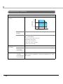
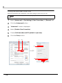
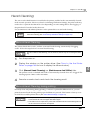
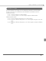
Post-Printing Verification Settings
This printer monitors dot missing periodically with the auto nozzle check system, and performs
the auto head cleaning if any dots are missing. Select from 6 modes that are available for
different levels of requirements for print quality and movement.
When extremely high reliability and safety are required, be sure to detect dot missing using an
application in addition to the printer driver setting. For the details, see "When Extremely High
Reliability and Safety are Required" on page 148.
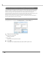
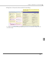
Sets this function from [Post-Printing Verification Settings] on [Maintenance And Utilities] of the
printer driver. The printer's Post-Printing Verification Settings can be checked using Self-test
Mode. For the details, see "Self-test Mode" on page 198.
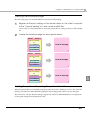
• High Reliability Mode (Void Image Print)
Missing dots check is performed after printing each page to check that dot missing has not
occurred. When dot missing is detected, the Void Image Print is performed at the bottom of
the previous page. And after the dot missing is resolved by the auto head cleaning, reprinting
starts from the corresponding page.
The Void Image is printed in solid black by default; however, other image files can also be
registered. Since dots are missing for the page on which the Void Image is printed, take proper
action such as discarding it.
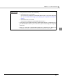
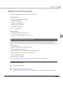
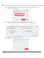
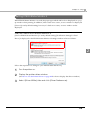
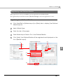
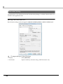
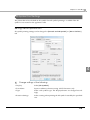
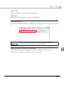
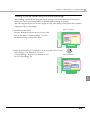
• High Reliability Mode (Reprint)
Missing dots check is performed after printing each page to check that dot missing has not
occurred. When dot missing is detected, the following screen of the EPSON Status Monitor 3 is
displayed. Select the next operation from [Restart printing] (printing the next data) and
[Reprint] (reprinting after dot missing is resolved by the auto head cleaning.)
When customer want to select this mode, do NOT uncheck [Use EPSON Status Monitor 3] of
[Driver Preferences] in [Driver Utilities] tab.
21
1
• Economy Mode for Low Print Volume (Void Image Print)
Missing dots check is performed after printing each page with removing the timer cleaning.
When dot missing (more than neighboring 2 dots missing) is detected, the Void Image Print is
performed at the bottom of the previous page. And after the dot missing is resolved by the
auto head cleaning, reprinting starts from the corresponding page.
The Void Image is printed in solid black by default; however, other image files can also be
registered.
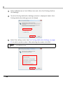
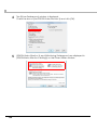
• Economy Mode for Low Print Volume (Reprint)
Missing dots check is performed after printing each page with removing the timer cleaning.
When dot missing (more than neighboring 2 dots missing) is detected, the EPSON Status
Monitor 3 is displayed. Select the next operation from [Restart printing] (printing the next
data) and [Reprint] (reprinting after dot missing is resolved by the auto head cleaning).
When customer want to select this mode, do NOT uncheck [Use EPSON Status Monitor 3] of
[Driver Preferences] in [Driver Utilities] tab.
• Anti-missing Read Mode
Does not perform missing dots check after printing each page, but checks missing dots while
not printing.
• Anti-missing Color Mode
Does not perform missing dots check after printing each page, but checks missing dots while
not printing. The condition for preventing missing colors due to missing dots is different,
depending on the firmware versions as follows:
Except firmware version AAExxxxx: Prevents missing colors due to missing dots on the condition with adjoining 2 dots in above and below or 3 dots in all nozzles. Does not perform head
cleaning to missing dots with less than 2 dots that are not adjoining.
Firmware version AAExxxxx: Prevents missing colors due to missing dots on the condition
with adjoining 3 dots in above and below or 10 dots in all nozzles.
* “x” of firmware version AAExxxxx shows any one alphanumeric character.
22
Chapter 1 Product Overview
In the High Reliability Mode or Economy Mode for Low Print Volume, printing takes more
time since the missing dots check is performed after printing each page.
Economy Mode for Low Print Volume has been added in Ver.WSN00180 or later of the
printer firmware. The firmware version can be checked using Self-test Mode. ("Self-test
Mode" on page 198)
When the printer driver’s version is Ver.1.3.0.0 or earlier, the mode cannot be changed to
Economy Mode for Low Print Volume, and the mode cannot be changed from Economy
Mode for Low Print Volume to another mode.
• These functions do not guarantee a 100 percent prevention of dot missing.
• Small amount of ink is used for detecting nozzle clogging.
• The auto head cleaning is performed automatically after nozzle clogging is detected. Ink
is expended during the head cleaning.
• Nozzle clogging detect function cannot be disabled.
• When you want to select [High Reliability Mode (Reprint)] or [Economy Mode for Low
Print Volume (Reprint)], do not uncheck [Use EPSON Status Monitor 3] of [Driver Preferences] in [Driver Utilities] tab.
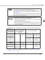
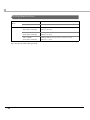
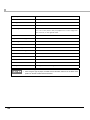
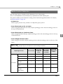
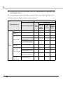
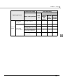
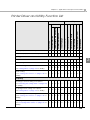
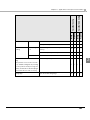
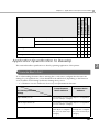
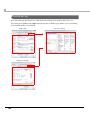
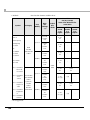
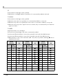
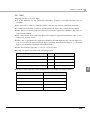
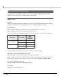
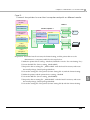
When an unrecoverable missing dot occurs, the printer operates differently for each mode as
shown below.
Post-Printing Verification Settings
High Reliability Mode
/ Anti-missing Read Mode
/Economy Mode for Low
Print Volume
1 dot
2 or more
dots
Except firmware
version AAExxxxx:
1 dot/2 dots except
for adjoining dots
Except firmware
version AAExxxxx:
Adjoining 2 dots
/3 or more dots
Firmware version
AAExxxxx:
Adjoining 2 dots
/9 or fewer dots
Firmware version
AAExxxxx:
Adjoining 3 dots
/10 or more dots
Maintenance
requirement
No error (power on)
Maintenance
requirement
X
(The printer
needs repair)
√
X
(The printer
needs repair)
Number of Unrecoverable Missing
Dots
Indications
Fatal error
√
Printer Usability
(Missing Dot
Acceptable
Print Mode*)
Anti-missing Color Mode
* For details on the Missing Dot Acceptable Print Mode, refer to "When an Unrecoverable
Missing Dot Occurs" on page 24.
23
1
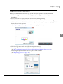
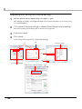
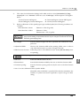
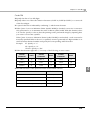
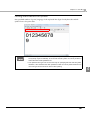
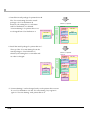
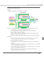
When an Unrecoverable Missing Dot Occurs
When 1 dot of unrecoverable missing dot is detected with the Post-Printing Verification Settings
for the printer driver set to the High Reliability Mode /Economy Mode for Low Print Volume /
Anti-missing Read Mode, the printer becomes in fatal error status. To continue printing, turn off
and on the printer and change the mode to the Missing Dot Acceptable Print Mode.
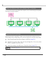
Missing dots check detects an unrecoverable missing dot.
A fatal occurs (LED indication: page 19)
The operator turns off and on the printer.
The printer starts up in the Missing Dot Acceptable Print Mode
(LED indication: page 19)
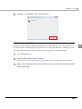
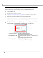
In the Missing Dot Acceptable Print Mode, it takes long to complete printing because missing
dots check is performed after printing each page. The EPSON Status Monitor 3 appears each
time of printing until the missing dot error is resolved. (The window may not appear depending
on the printer driver version.)
24
Chapter 1 Product Overview
• The procedure to check the Missing Dot Acceptable Print Mode is different depending
on the printer driver version. See the following:
∗ Printer Driver Ver1.1.0.0 or earlier
The procedure is not displayed in the EPSON Status Monitor 3. Check the LED indication. ("Unrecoverable nozzle clogging error (Missing Dot Acceptable Print Mode)" on
page 19)
∗ Printer Driver Ver1.2.0.0 or later
The procedure is displayed in the EPSON Status Monitor 3.
• In the Missing Dot Acceptable Print Mode, EPSON Status Monitor 3 is displayed even if
[Use EPSON Status Monitor 3] is not selected in [Driver Preferences] from the [Driver
Utilities] tab.
• When 2 or more dots of unrecoverable missing dot is detected in the Missing Dot
Acceptable Print Mode, maintenance is requested and the printer needs repair.
25
1
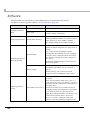
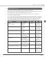
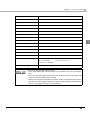
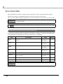
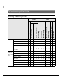
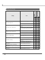
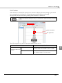
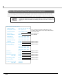
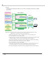
Software
Various utilities are provided to system administrators and application developers.
For details on how to get the software, see "Download" on page 138.
Purpose
Installing the printer
driver
Monitoring the printer
Name
Specifications
Printer Driver
Installs printer driver and executes port setting.
Easy setup
Installs printer driver, executes port setting and
network setting of the printer.
EPSON Status Monitor 3
Displayed on front of the application while
printing. Installed simultaneously with the printer
driver, and selects from enable or disable.
(The default setting when installed: Disable)
Creates an install package file for installing and
setting the printer driver and executing the port
setting.
Install Assistant
Distributing the printer
driver and setting
The computer with activating the install
package file automatically executes installing
the printer driver, setting the printer driver and
executing port setting. The printer setting is not
executed.
Creates an install package for each printer for
the network printer.
Printer Setting
Executes printer setting. Creates a setting file
and applies it simultaneously to a number of
printers.
“Printer Setting” can not be executed in
computer without installing the printer driver.
Replacing the USB
model
USB Replacement Service
Service installed as a resident program on the
computer
When the TM-C3400 is replaced for service or
other reason, this detects the printer connection
and automatically changes the output printer of
the printer driver.
This allows the printer to be replaced without
changing settings in the application. (The printer
is not replaced if a port is specified for the
application output destination. The printer is only
replaced if the printer driver is specified.)
There is no need to change the USB serial
number of the TM-C3400 before replacement.
26
Chapter 1 Product Overview
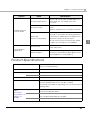
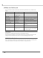
Purpose
Name
EpsonNet Simple Viewer
EpsonNet Config
Specifications
The user can check status of EPSON printer on
network with this. The setting can not be
executed.
The user can check and executes the network
printer.
Applies it simultaneously to a number of printers.
Administering the
network printer
WebConfig
The user can execute and check the network
information of the printer by entering IP address
of the printer to address bar of the Web browser.
(Function of the printer)
One printer can be set and checked.
This can not be used for the printer with default
condition since IP address is not available.
EpsonNet SDK
The software development kit for monitoring the
printer via network.
Sample Program
This is the sample programs for using TM-C3400.
(VB.NET, C++ is prepared for all programs. VB 6.0,
C# is prepared for some programs.)
Developing the
application
Product Specifications
Printing method
Serial ink jet, dot matrix
Three-color (CMY) printing
Paper feed
Autocutter
Forward and reverse friction feed
Cutting method
By separated-blade scissors
Auto-cut type
Full cut
Graphic resolution
360 dpi × 180 dpi, 360 dpi × 360 dpi, 720 dpi × 360 dpi
Print speed
92 mm/s (printing width 56 mm, 360 dpi × 180 dpi)
82 mm/s (printing width 72 mm, 360 dpi × 180 dpi)
The print speed is different depending on the resolution and the
printing width.
Paper
Type
(See "Paper
Specifications" on Classification
page 31 for
details)
Form
Plain Media, Plain Media Label, Fine Media, PET Film,
Synthetic Media, Wrist Band
Receipt, Black Mark Receipt, Full-page Label
Die-cut Label, Black Mark Die-cut Label
Roll paper, Fanfold paper
27
1
Ink cartridge
3-color exclusive integrated ink cartridge
(See "Ink Cartridge" on page 53 for
details.)
(Model number: SJIC15P)
USB model
USB 2.0 high speed
Ethernet model
Ethernet (100 Base-TX/10 Base-T)
USB 2.0 high speed
(For the Ethernet interface model, USB connection is also
available. Ethernet connection and USB connection cannot be
used simultaneously.)
Interface
Barcode/
two-dimensional
code printing
Barcode
UPC-A, UPC-E, JAN 8 (EAN 8), JAN 13 (EAN 13), Code 39, ITF,
Codabar, Code 93, Code 128, GS1-128,
Barcode
identification rate GS1 DataBar Omnidirectional, GS1 DataBar Truncated,
GS1 DataBar Limited, GS1 DataBar Expanded
ANSI rank D
(based on Seiko
Epson Corporation
standard)
Two-dimensional
code printing
Power supply
Temperatures/
humidity
PDF417, QR code, Maxi Code, S1 DataBar Stacked,
GS1 DataBar Stacked Omnidirectional,
GS1 DataBar Expanded Stacked, Composite Symbology,
DataMatrix, Aztec
AC 100 to 240V
Printing
10 to 35°C, 20 to 80%RH (no condensation)
Storage
When packed (ink not loaded): -20 to 60°C, 5 to 85%RH (no
condensation)
(See
"Environmental
Conditions" on
page 56 for
details.)
-20°C or 60°C: up to 120 hours
Ink loaded: -20 to 40°C
-20°C: up to 120 hours
0 to 30°C: up to 6 months
40°C: up to a month
28
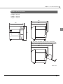
Overall dimensions (H × W × D)
261 × 255 × 275 mm (excluding protrusions)
Weight (mass)
Approximately 10.0 kg
(Except for ink cartridge, roll paper, paper ejection tray)
Chapter 1 Product Overview
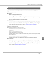
Hardware Requirements
OS
Microsoft Windows 7 SP1 (32 bit/ 64 bit)
Microsoft Windows Vista SP2 (32 bit/ 64 bit)
Microsoft Windows XP SP3 (32 bit)
Microsoft Windows XP SP2 (64 bit)
Microsoft Windows 2000 SP4 (32 bit)
Microsoft Windows Server 2008 R2 SP1
Microsoft Windows Server 2008 SP2 (32 bit/ 64 bit)
Microsoft Windows Server 2003 R2 SP2 (32 bit/ 64 bit)
Computer
Must support the following computers that run the above
operating systems.
1
• PC/AT compatible
CPU
Computers with a processor of 1 GHz or better are
recommended.
Intel Pentium/Celeron series, AMD Athlon/Duron family, or
processors that are compatible with these are recommended.
RAM
HDD
Windows 2000
256 MB or larger is recommended
Windows XP /
Vista / 7 /
Server 2003/
Server 2008
512 MB or larger is recommended
Free space must be 250 MB or larger
• The minimum requirements of the above system may not satisfy the minimum
requirements of the OS. In this case, satisfy the minimum requirements of the OS.
• The printers on the network is supported up to 64 printers. In that case, if the minimum
requirements above are not met, the printer may not be able to come up to its standard.
29
Printing Specifications
Printable
area
Roll paper
Minimum width 26 mm, Maximum width 104 mm
Fanfold paper
Minimum width 46 mm, Maximum width 104 mm
Print speed
360 × 180 dpi
(horizontal × vertical)
Printing width 56 mm: 92 mm/s, 72 mm: 82 mm/s,
104 mm: 68 mm/s
360 × 360 dpi
(horizontal × vertical)
Printing width 56 mm: 47 mm/s, 72 mm: 42 mm/s,
104 mm: 35 mm/s
720 × 360 dpi
(horizontal × vertical)
Printing width 56 mm: 23 mm/s, 72 mm: 21 mm/s,
104 mm: 17 mm/s
dpi : dots per 25.4 mm (dots per inch)
30
Chapter 1 Product Overview
Paper Specifications
The following is the type and the size of paper specified for this printer.
When using paper other than specified paper, paper feed accuracy, barcode detection accuracy,
printing quality may be degraded or frequent paper jam may occur.
As for black mark die-cut label (synthetic media label), use paper whose outer edges are
removed only on the right and left.
Do not use the label paper with synthetic media labels on the paper backing (liner). Depending
on the temperature and humidity, the synthetic media labels and paper backing have different
ratios of expansion and contraction, and this causes the paper to curl. If the paper curls, the
paper may be rubbed by the print head and become contaminated, or the paper may jam.
Paper type
Category
Form
Receipt
Plain Media
(Continuous paper)
Fine Media
{1.18 to 4.25"}
PET Film
(Paper width)
Roll paper
30 to 108 mm
Black Mark Receipt
Plain Media
(Continuous paper with black marks)
Fine Media
{1.18 to 4.25"}
PET Film
(Paper width)
Roll paper
30 to 108 mm
Black Mark Receipt
Plain Media
(Continuous paper with black marks)
Fine Media
{1.97 to 4.25"}
PET Film
(Paper width)
Full-page Label
Die-cut Label
Plain Media Label
Fanfold paper
Roll paper
50 to 108 mm
25.4 to 108 mm
Fine Media Label
{1 to 4.25"}
Synthetic Media Label
(Label width)
Plain Media Label
Roll paper
25.4 to 108 mm
Fine Media Label
{1 to 4.25"}
Synthetic Media Label
(Label width)
Black Mark Die-cut Label
Plain Media Label
(Die-cut label with black marks)
Fine Media Label
{1 to 4.25"}
Synthetic Media Label
(Label width)
Black Mark Die-cut Label
Plain Media Label
(Die-cut label with black marks)
Fine Media Label
Roll paper
Fanfold paper
1
Width
25.4 to 108 mm
46 to 108 mm
{1.81 to 4.25"}
(Label width)
Wrist Band
Synthetic Media
Roll paper
30 mm {1.18"}
28.6 mm
(Paper width)
31
Receipt
This is continuous paper.
Paper type
Plain Media, Fine Media, PET Film
Form
Roll paper
Paper width
30 to 108 mm
Paper length
15 to 1117.6 mm
Paper thickness
0.085 to 0.151 mm
Roll paper core
Outside diameter: 44.1 mm
External diameter
Maximum 101.6 mm
Winding direction
Printing face must be facing outside.
Do not use the paper with a hole or cutout.
32
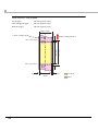
Chapter 1 Product Overview
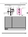
Black Mark Receipt
<Printing side>
Center of black marks
Center of paper
width
Paper feeding
direction
Interval of
black marks
Center of paper width
Black mark
length
<Back side>
1
Perforation position
0.5 mm or more
(When using fanfold
paper)
Black mark width
Paper type
Plain Media, Fine Media, PET Film
Form
Roll paper
Paper width
30 to 108 mm
Paper length
15 to 1117.6 mm
Black mark width
13 mm or more
Black mark length
5 mm or more
Black mark centering position
8.5 ± 1 mm
Black mark interval
15 to 1117.6 mm
Paper thickness
0.085 to 0.151 mm
Roll paper core
Outside diameter: 44.1 mm
External diameter
Maximum 101.6 mm
Winding direction
Printing face must be facing outside.
Black mark
receipt
Do not use the paper with a hole or cutout.
33
Paper type
Plain Media, Fine Media, PET Film
Form
Fanfold paper
Paper width
50 to 108 mm
Paper length
15 to 304.8 mm
Black mark width
13 mm or more
Black mark length
5 mm or more
Black mark centering position
8.5 ± 1 mm
Black mark interval
15 to 304.8 mm
Paper thickness
0.119 to 0.151 mm
Pitch of perforated line:
203.2 to 304.8 mm
Form of perforated line
Number of folds
Plain media : 1 mm uncut, 5 mm cut
Fine media
: 1 mm uncut, 5 mm cut
PET film
: 0.6 mm uncut, 8.4 mm cut
500 or less
• Do not use the paper with a hole or cutout.
• When using fanfold paper, the black marks must be at least 0.5 mm from the perforated
lines.
• Make sure to keep the same position of the black marks to the perforated lines (position
that can be detected by black mark sensor) when inserting the paper from either side in
order to use the paper inserting from reverse direction.
34
Chapter 1 Product Overview
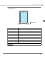
Full-page Label
Backing paper width
Label width
Edge cutoff
1
Backing paper
Label area
Edge cutoff
Paper type
Plain Media Label, Fine Media Label, Synthetic Media Label
Form
Roll paper
Backing paper width
30 to 112 mm
Label width
25.4 to 108 mm
Label length
15 to 1117.6 mm
Edge cutoff on left/right side
2 ± 0.5 mm
Paper thickness
0.128 to 0.195 mm
Roll paper core
Outside diameter: 44.1 mm
External diameter
Maximum 101.6 mm
Winding direction
Printing face must be facing outside.
Do not use the paper with a hole or cutout.
35
Die-cut Label
Label length
Backing paper width
Gap between
labels
Edge R
Backing paper
Label area
Edge cutoff
Label width
Paper type
Plain Media Label
Form
Roll paper
Backing paper width
30 to 112 mm
Label width
25.4 to 108 mm
Label length
25.4 to 1117.6 mm
Edge cutoff
(To use a label with a label length of 25.4 mm or less, see
descriptions for Black Mark Die-cut Label.)
Gap between labels
3 to 6 mm
Edge cutoff on left/right side
2 ± 0.5 mm
Label edge R
2 mm or less
Paper thickness
0.128 mm
Roll paper core
Outside diameter: 44.1 mm
External diameter
Maximum 101.6 mm
Winding direction
Printing face must be facing outside.
Do not use the paper with a hole or cutout.
36
Chapter 1 Product Overview
Paper type
Fine Media
Form
Roll paper
Backing paper width
30 to 112 mm
Label width
25.4 to 108 mm
Label length
25.4 to 1117.6 mm
(To use a label with a label length of 25.4 mm or less, see
descriptions for Black Mark Die-cut Label.)
Gap between labels
3 to 6 mm
Edge cutoff on left/right side
2 ± 0.5 mm
Label edge R
2 mm or less
Paper thickness
0.145 mm
Roll paper core
Outside diameter: 56.8 mm
External diameter
Maximum 101.6 mm
Winding direction
Printing face must be facing outside.
1
Do not use the paper with a hole or cutout.
37
Paper type
Synthetic Media Label
Form
Roll paper
Backing paper width
30 to 112 mm
Label width
25.4 to 108 mm
Label length
With the roll paper core of 44.1 mm or more: 50.8 to 1117.6 mm
With the roll paper core of 56.8 mm or more: 32 to 1117.6 mm
(To use a label with a label length of less than the abovementioned, see descriptions for Black Mark Die-cut Label.)
Gap between labels
3 to 6 mm
Edge cutoff on left/right side
2 ± 0.5 mm
Label edge R
2 mm or less
Paper thickness
0.195 mm
Roll paper core
Outside diameter: 44.1 mm
External diameter
Maximum 101.6 mm
Winding direction
Printing face must be facing outside.
Do not use the paper with a hole or cutout.
38
Chapter 1 Product Overview
Black Mark Die-cut Label
Black mark
length
<Back side>
Center of black marks
Center of paper
width
Paper feeding
direction
Interval of
black marks
Center of paper width
<Printing side>
Perforation position
2 mm or more
( W h e n u s i n g fa n fold paper)
1
Backing paper
Label area
Black mark width
When removing right and left fringes only
(Black Mark Die-cut Label)
When removing all the fringes
Paper width
Paper width
Gap between
labels
Edge R
Gap between
labels
Edge R
Label length
Label length
Label
Label width
Edge cutoff
Edge cutoff
Backing paper
Label area
Label chaff
Label width
Edge cutoff (edge)
Edge cutoff (edge)
39
Paper type
Plain Media
Form
Roll paper
Backing paper width
30 to 112 mm
Label width
25.4 to 108 mm
Label length
25.4 to 1117.6 mm
(For the label length of 15 to less than 25.4 mm, use paper whose
outer edges are removed only on the right and left.)
Gap between labels
3 to 6 mm
Edge cutoff on left/right side
2 ± 0.5 mm
Label edge R
2 mm or less
Black mark width
13 mm or more
Black mark length
5 mm or more
Black mark centering position
8.5 ± 1 mm
Black mark interval
15 to 1117.6 mm
Paper thickness
0.128 mm
Roll paper core
Outside diameter: 44.1 mm
External diameter
Maximum 101.6 mm
Winding direction
Printing face must be facing outside.
• Do not use the paper with a hole or cutout.
• when using this type of paper, the label end and the black mark end of the black mark
position on the die-cut label must be matched.
40
Chapter 1 Product Overview
Paper type
Fine Media Label
Form
Roll paper
Backing paper width
30 to 112 mm
Label width
25.4 to 108 mm
Label length
25.4 to 1117.6 mm
(For the label length of 15 to less than 25.4 mm, use paper whose
outer edges are removed only on the right and left.)
Gap between labels
3 to 6 mm
Edge cutoff on left/right side
2 ± 0.5 mm
Label edge R
2 mm or less
Black mark width
13 mm or more
Black mark length
5 mm or more
Black mark centering position
8.5 ± 1 mm
Black mark interval
15 to 1117.6 mm
Paper thickness
0.145 mm
Roll paper core
Outside diameter: 56.8 mm
External diameter
Maximum 101.6 mm
Winding direction
Printing face must be facing outside.
1
• Do not use the paper with a hole or cutout.
• when using this type of paper, the label end and the black mark end of the black mark
position on the die-cut label must be matched.
41
Paper type
Synthetic Media Label
Form
Roll paper
Backing paper width
30 to 112 mm
Label width
25.4 to 108 mm
Label length
Only the Black Mark Die-Cut Label
15 to 1117.6 mm {0.59" to 44"}: use paper whose outer edges are
removed only on the right and left.
Gap between labels
3 to 6 mm
Edge cutoff on left/right side
2 ± 0.5 mm
Label edge R
2 mm or less
Black mark width
13 mm or more
Black mark length
5 mm or more
Black mark centering position
8.5 ± 1 mm
Black mark interval
15 to 1117.6 mm
Paper thickness
0.195 mm
Roll paper core
Outside diameter: 44.1 mm
External diameter
Maximum 101.6 mm
Winding direction
Printing face must be facing outside.
• Do not use the paper with a hole or cutout.
• when using this type of paper, the label end and the black mark end of the black mark
position on the die-cut label must be matched.
42
Chapter 1 Product Overview
Paper type
Plain Media Label, Fine Media Label
Form
Fanfold paper
Backing paper width
50 to 112 mm
Label width
46 to 108 mm
Label length
15 to 301.8 mm
Gap between labels
3 to 6 mm
Edge cutoff on left/right side
2 ± 0.5 mm
Label edge R
2 mm or less
Black mark width
13 mm or more
Black mark length
5 mm or more
Black mark centering position
8.5 ± 1 mm
Black mark interval
15 to 304.8 mm
Paper thickness
0.145 to 0.161 mm
Perforated line pitch:
203.2 to 304.8 mm
Perforated line form:
1
Plain media label
: 1 mm uncut, 5 mm cut
Fine media label
: 1 mm uncut, 5 mm cut
Synthetic media label :
Number of folds:
500 or less
• Do not use the paper with a hole or cutout.
• When using fanfold paper, the black marks must be at least 2 mm from the perforated
lines.
• when using this type of paper, the label end and the black mark end of the black mark
position on the die-cut label must be matched.
• Make sure to keep the same position of the black marks to the perforated lines (position
that can be detected by black mark sensor) when inserting the paper from either side in
order to use the paper inserting from reverse direction.
43
Wrist Band
<Back side>
Center of paper width
<Printing side>
Center of paper width
Center of black marks
Interval of black marks
Black mark length
Paper feeding
direction
Black mark paper
Black mark width
44
Paper type
Synthetic Media
Specified original paper
PDC Compucolor 8000 Series 7.5 mil Rectangular Band (Code:
8000-11-PDL)
Form
Roll paper
Backing paper width
28.6, 30 mm
Black mark width
13 mm or more
Black mark length
9 mm or more
Black mark centering position
8.5 ± 1 mm
Black mark interval
292.1 mm
Paper thickness
0.19 mm
Roll paper core
Outside diameter: 56.8 mm
External diameter
Maximum 101.6 mm
Winding direction
Printing face must be facing outside.
Hole, notch
Diameter: 2.5 mm or less
Chapter 1 Product Overview
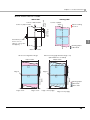
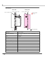
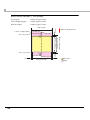
Print Area and Cutting Position
Receipt / Roll paper
Top margin:
2.0 mm (typical value)
Left and right margin:
2.0 mm (typical value)
Bottom margin:
2.0 mm (typical value)
2.0 mm
Paper width
Center of paper width
Paper feeding direction
1
2.0 mm
2.0 mm
Auto-cut position
15.0 mm or more
(When auto-cutting)
11.0 mm or more
Auto-cut position
Print area width
2.0 mm
Print area
Paper
When the roll paper option is set to “Banner Mode,” a top margin is set only on the first
page of the print job, and not on the rest. A bottom margin is set on the last page of the print
job.
45
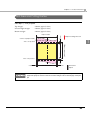
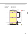
Full-page Label / Roll paper
Top margin (inside the label):
2.0 mm (typical value)
Left and right margin (inside the label):
2.0 mm (typical value)
Bottom margin (inside the label):
2.0 mm (typical value)
2.0 mm
Paper width
Center of paper width
Paper feeding direction
15.0 mm or more
(When auto-cutting)
11.0 mm or more
Auto-cut position
2.0 mm
Auto-cut position
2.0 mm
2.0 mm
Print area width
2.0 mm
Print area
2.0 mm
Label area
Backing paper
When the roll paper option is set to “Banner Mode,” a top margin is set only on the first
page of the print job, and not on the rest. A bottom margin is set on the last page of the print
job.
46
Chapter 1 Product Overview
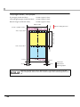
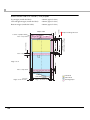
Die-cut Label / Roll paper
Left and right margin (inside the label):
2.0 mm (typical value)
Bottom margin (inside the label):
2.0 mm (typical value)
Paper width
Center of paper width
1.5 mm
2.0 mm (typical value)
2.0 mm
Top margin (inside the label):
Paper feeding direction
3.0 to 6.0 mm
11.0 mm or more
18.0 mm or more
(When auto-cutting)
Auto-cut position
1
1.5 mm
2.0 mm
Auto-cut position
2.0 mm
2.0 mm
Print area width
2.0 mm
Print area
2.0 mm
Label area
Backing paper
47
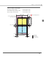
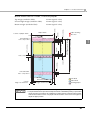
Black Mark Receipt / Roll paper
Top margin:
2.0 mm (typical value)
Left and right margin:
2.0 mm (typical value)
Bottom margin:
2.0 mm (typical value)
2.0 mm
Paper width
Center of paper width
Paper feeding direction
2.0 mm
2.0 mm
Auto-cut position
15.0 mm or more
(When auto-cutting)
11.0 mm or more
Auto-cut position
Print area width
2.0 mm
Print area
Paper
48
Chapter 1 Product Overview
Bottom margin:
2.0 mm (typical value)
Center of paper width
Paper width
11.0 mm or more
Perforated line
Auto-cut position
2.0 mm
Auto-cut position
2.0 mm
Paper feeding
direction
1
Interval of perforated lines: 203.2 mm to 304.8 mm
2.0 mm (typical value)
Issuing pitch: 15.0 mm or
more (When auto-cutting)
Left and right margin:
0.5 to 1.0 mm
2.0 mm (typical value)
2.0 mm
Top margin:
2.0 mm
Black Mark Receipt / Fanfold paper
Perforated line
Auto-cut position
Print area
2.0 mm
Print area width
2.0 mm
Paper
49
2.0 mm (typical value)
Bottom margin (inside the label):
2.0 mm (typical value)
Paper width
Center of paper width
3.0 to 6.0 mm
11.0 mm or more
Auto-cut position
2.0 mm
Auto-cut position
Paper feeding direction
18.0 mm or more
(When auto-cutting)
Left and right margin (inside the label):
1.5 mm
2.0 mm (typical value)
2.0 mm
Top margin (inside the label):
1.5 mm
Black Mark Die-cut Label / Roll paper
1.5 mm
Edge cutoff
Auto-cut position
2.0 mm
Edge cutoff 2.0 mm
50
Print area width
2.0 mm
Edge cutoff 2.0 mm
Print area
Label area
Backing paper
Chapter 1 Product Overview
Black Mark Die-cut Label / Fanfold paper
2.0 mm (typical value)
Bottom margin (inside the label):
2.0 mm (typical value)
Paper width
2.0 mm
Center of paper width
Issuing pitch: 18.0 mm or
more (When auto-cutting)
11.0 mm or more
2.0 mm
3.0 to 6.0 mm
Perforated line
Auto-cut position
1.5 to 3.0 mm
Auto-cut position
1.5 to 3.0 mm
Paper feeding
direction
1
Interval of perforated lines: 203.2 mm to 304.8 mm
Left and right margin (inside the label):
1.5 to 3.0 mm
2.0 mm (typical value)
0.5 to 1.0 mm
Top margin (inside the label):
Perforated line
Auto-cut position
Print area width
2.0 mm
Edge cutoff 2.0 mm
2.0 mm
Edge cutoff 2.0 mm
Print area
Label area
Backing paper
• Make sure to adjust perforated lines to an integral multiple of issuing pitch.
• The perforated line and print area overlap each other to destabilize printing or perforated
line and the auto-cut position are misaligned to shorten the life of the autocutter if paper
without black marks is used. Use paper with black marks on the back of the paper to
adjust the paper position.
51
Wrist Band / Roll paper
Top margin:
2.0 mm (typical value)
Left and right margin:
2.0 mm (typical value)
Bottom margin:
2.0 mm (typical value)
2.0 mm
Paper width
Center of paper width
Paper feeding direction
292.1 mm
288.1 mm
Auto-cut position
2.0 mm
Auto-cut position
2.0 mm
52
Print area
width
2.0 mm
Print area
Paper
Chapter 1 Product Overview
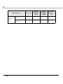
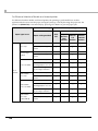
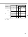
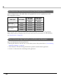
Paper Ejection Tray
Black Mark
Receipt
Black Mark
Die-cut Label
Paper type
Plain Media, Fine Media, PET Film
Paper form
Fanfold paper
Paper size
Width 76 to 105 mm × length 54 to 148 mm
Paper
thickness
0.119 to 0.151 mm
Paper type
Plain Media, Fine Media
Paper form
Fanfold paper
Paper size
Width 76 to 105 mm × length 54 to 148 mm
Paper
thickness
0.145 to 0.161 mm
1
• The paper ejection tray cannot store multiple sheets of roll paper.
• The paper ejection tray may not hold the paper perfectly, depending on the condition of
the paper or printing.
Ink Cartridge
Model number
SJIC15P
Type
3-color exclusive integrated ink cartridge
Ink color
Cyan, magenta, yellow
Ink type
Pigment ink
Ink life
6 months after loading to the printer, 2 years after manufacturing
Temperatures
Transport
-20 to 60°C (up to 5 days for 60°C)
Storage
-20 to 40°C (up to a month for 40°C)
Installation
-20 to 40°C (up to a month for 40°C)
53
Electrical Characteristics
Power supply
Power supplied by AC adapter accessory (PS-180)
Input voltage (rated)
North America / Japan: AC 100 to 125V ()
Other countries:
Frequency (rated)
50 Hz to 60 Hz
Power
consumption
Operating
Approximately 26W
Stand-by
Approximately 5W
When power is
OFF
Approximately 0.5W
AC 100 to 240V
• Use the dedicated AC adapter included in the product package.
• For the Ethernet cable, use cable with CAT5e or higher shielding.
54
Chapter 1 Product Overview
Reliability
Life
Print head
6,000 million shots/nozzle
Paper feed
mechanism
1,500,000 pages or the number of pages that reaches the
following paper length fed.
• Plain Media: 150 km
• Fine Media: 75 km
• PET Film: 50 km
• Continuous label paper (Plain Media): 100 km
• Continuous label paper (Fine Media): 50 km
• Continuous label paper (Synthetic Media): 10 km
1
• Die-cut label (Plain Media): 150 km
• Die-cut label (Fine Media): 150 km
• Die-cut label (Synthetic Media): 50 km
• Wrist band (8000-11-PDL): 60 km
Autocutter
mechanism
• Plain Media: 1,500,000 cuts
• Fine Media: 750,000 cuts
• PET Film: 500,000 cuts
• Continuous label (Plain Media): 750,000 cuts
(Add extra 250,000 cuts with cleaning the cutter blade)
• Continuous label (Fine Media): 500,000 cuts
• Continuous label (Synthetic Media): 100,000 cuts
• Die-cut label backing paper (Plain Media): 1,500,000 cuts
• Die-cut label backing paper (Fine Media): 1,500,000 cuts
• Die-cut label backing paper (Synthetic Media): 500,000 cuts
• Wrist band (8000-11-PDL): 200,000 cuts
Carriage
mechanism
6 million passes (3 million carriage returns)
Maintenance is requested when it reaches 20,000,000 passes (the
printer will stop)
(For details on the LED lighting/flashing patterns when
maintenance is requested, see "Status/Error Indications" on page
19.)
MTBF
75000 hours
MCBF
9,800,000 passes
55
Environmental Conditions
Item
Temperatures/
humidity
Specification
Printing
10 to 35°C, 20 to 80%RH (no condensation)
Humidity (%)
Temperatures (°C)
Barcode
printing
15 to 35°C, 20 to 80%RH (no condensation)
Storage
When packed (ink not loaded): -20 to 60°C, 5 to 85%RH
(no condensation)
-20°C or 60°C: up to 120 hours
Ink loaded: -20 to 40°C
-20°C: up to 120 hours
0 to 30°C: up to 6 months
40°C: up to a month
Pressure
(elevation)
Operating
700 to 1060 hPa (approximately 0 to 2500 m above sea level)
Not operating
(including in
transportation)
700 to 1060 hPa (approximately 0 to 2500 m above sea level)
Acoustic noise
During
operation
Approximately54 dB (ANSI Bystander position)
(including using
the autocutter)
56
(Based on Epson evaluation conditions including the use of the
autocutter)
Chapter 1 Product Overview
External Dimensions
• Height: 261 mm
• Width: 255 mm
• Depth: 275 mm
300
255
275
1
261
457 (when the paper ejection tray is extended)
388 (when the paper ejection tray is shortend)
300
[Unit: mm]
57
Power Supply Unit (PS-180)
136
68
32
[Unit: mm]
Electric
characteristics
Input conditions
Input voltage (rated): 100 to 240V AC
Frequency (rated): 50/60 Hz ± 3 Hz
Power consumption (rated): 100VA
Output
conditions
Output voltage (rated): 24VDC ± 5%
Output current (rated): 2.0A
Output electric power (rated): 48VA
Output peak current: 4.5A
Case specifications
Dimensions
68 × 136 × 32 mm {2.68 × 5.35 × 1.26"}
(H × W × D)
(excluding protrusions)
Weight
Approximately 0.4 kg {14.11 oz} (excluding the AC cable)
Color
Black (matte)
Material
No specific brominated flame retardants, such as PBBE and PBB, are used in this product.
AC cable selection
Select an AC cable that satisfies the following conditions.
• Safety standard product
• Plug with PE terminal
Ground connections
Be sure to ground for safety
58
Chapter 1 Product Overview
Restrictions
Printer environment
• Drivers for TM printers (APD, OPS/JavaPOS) of Seiko Epson Corporation cannot be used for
this printer.
The TM-C3400 printer driver can be installed and used on a computer with the APD and
OPS/JavaPOS installed.
Installation environment for the printer driver
• The printer driver for Ethernet interface model cannot be installed with a USB interface model
printer connected. In this case, turn off the USB interface model printer before installing the
printer driver for Ethernet interface model.
• When the printer driver is installed using point and print, printing can be performed but
obtaining the printer status can not be executed.
• When setting the printer driver using point and print, setting may be made by accessing the
server via a network. Be sure to make the setting with the printer connected.
• When using shared printer and local printer on one client computer, install the printer driver
for the local printer before installing the printer driver for the shared printer.
• When using this printer in the same environment as a version of the APD earlier version than
APD 4.03, Install the APD first, and then install the printer driver for this printer.
Install package of the printer driver
• When the printer driver is installed using the install package of the USB interface model, the
status of other computers on the network cannot be acquired, even if the setting for sharing
this printer is made. And the status cannot be acquired with the EPSON Status Monitor 3 or
other applications; however, printing is possible. To avoid the limitations, install the printer
driver without using the install package, and make the settings.
• The settings of [Monitoring Preferences] in [Driver Utilities] tab is not reflected for the install
package. The default setting is the error display of the EPSON Status Monitor 3 (Notifies when
printing is impossible and maintenance is requested.) When changing the setting, make the
setting for each installation environment.
• In a Windows 2000 environment, if the printer driver can not be installed when the install
package is executed, it is possible that the printer is registered as an “Unknown device”.
Delete the “Unknown device” and then execute the install package.
("Printer Driver cannot be Installed (Windows 2000)" on page 219)
• In a Windows 2000 environment, if the TM-C3400 printer driver is already installed and the
version is different from the version of the printer driver of the install package, the settings of
the existing printer driver may change. (This does not affect other printer drivers that are not
for the TM-C3400.)
To keep the existing settings, you must save the settings before executing the install package,
and then restore the settings after the install package is executed. ("Printer Driver is Already
Installed (Windows 2000)" on page 219)
59
1
Paper
• When using a full-page label, remove the ejected label each time the printing is finished. Otherwise, a part of printed label may be cut, or a cutter error may occur. (See "Status/Error Indications" on page 19.)
• When cutting the full-page label, adhesive from labels may stick to the fixed blade of the
autocutter, which may prevent the autocutter from cutting paper cleanly. If this happens, clean
the cutter blade. For details, see "Cleaning the Autocutter" on page 203.
Turning on/off the power switch
• If you turn the printer off without using the power switch, the print head may not return to its
home position. In this case, the next time the printer is turned on, auto head cleaning is performed, which wastes ink.
Printing
• For the USB interface model, it takes time for the next printing if you turn the printer off and
on after printing.
• The ink cartridge contains 3 colors of ink. Even when one particular color is specified, all 3 colors of ink are used for printing and for keeping the print head in good condition. When the ink
level of even one color reaches the lowest limit, the printer stops printing.
• The colors of printouts may become abnormal if you tilt this printer or subject the printer to
any shocks. When you move this printer after ink charging, check the colors by performing a
test print.
If the colors of printouts are not normal, perform head cleaning. See "Manual Head Cleaning"
on page 201 for how to perform head cleaning.
• When printing image data, white lines (lines shown in white) or black lines (overlapping of
image) may appear at about 1 inch intervals in the print result. By setting [Print Head Alignment] - [Media Feed Adjustment] in [Maintenance And Utilities] tab, this can be reduced
but cannot be removed completely.
• When printing image data, change of color tone may appear at 1 inch intervals in the print
result.
60
Chapter 2 Setup
Setup
This chapter describes setup and installation of the product and peripherals.
When You Use This Printer for the First Time
Do not turn on the printer power until installation of the printer driver is completed.
Ink charging and media position detection setting are necessary before you use this printer for
the first time.
Follow the steps below.
1
2
3
Load the roll paper.
For details, see Loading/Replacing the Roll Paper on page 79.
2
Turn on the printer.
Load a new ink cartridge.
For details, see Loading/Replacing the Ink Cartridge on page 66.
• Ink charging starts after the ink cartridge cover is closed.
• When the ink cartridge is installed for the first time, the printer takes
approximately 8 minutes for ink charging.
The POWER LED flashes during ink charging. Do not turn
off the printer or open the roll paper cover or the ink cartridge cover.
If the power is turned off, the roll paper cover is opened, or
the ink cartridge cover is opened during ink charging, ink
charging will restart from the beginning and an extremely
large amount of ink will be consumed.
• When ink charging finishes, the POWER LED stops flashing and stays on.
4
Set the media position detection of the printer for the paper type you
will be using.
For details, see 2. Setting for media position detection on page 82.
61
• The colors of printouts may become abnormal if you tilt this printer or subject the printer
to any shocks. When you move this printer after ink charging, check the colors by performing a test print.
• If the colors of printouts are not normal, perform head cleaning. See Manual Head
Cleaning on page 201 for how to perform head cleaning.
• If you turn the printer off without using the power switch, the print head may not return to
its home position. In this case, the next time the printer is turned on, the auto head
cleaning is performed, which wastes ink.
62
Chapter 2 Setup
Flow of Setup
This chapter consists of the following sections along with the setup flow of the product and peripherals.
1. Installing the Printer (page 64)
2. Connecting the Power Supply Unit (PS-180) (page 65)
3. Loading/Replacing the Ink Cartridge (page 66)
4. Connecting the Printer to the Host Computer (page 68)
2
5. Installing the Driver (page 70)
6. Setting the DIP Switches (page 77)
7. Loading/Replacing the Paper (page 79)
8. Attaching/Adjusting the Paper Ejection Tray (page 99)
9. Attaching the Power Switch Cover (page 101)
10. Setting the Printer Driver (page 103)
63
Installing the Printer
Install the printer in an appropriate location with sufficient space around it.
Important Notes on Installation
261
100
275
255
[Unit: mm]
• The printer must be installed horizontally.
• Leave enough space in front of the printer for the ink cartridge cover and the roll paper cover
to be fully opened.
• Do not place the printer in a dusty location.
• Protect the printer from heavy impacts. They may cause defective print.
• Do not allow cables to get caught or foreign matter to accumulate under the printer.
• Make sure that there is at least 100 mm of space behind the printer back when installing.
• Do not put a heavy object (of 10 kg or more) or an object that vibrates on the printer.
64
Chapter 2 Setup
Connecting the Power Supply Unit (PS-180)
Use the PS-180 or an equivalent product as the power supply unit.
WARNING
• Always use the EPSON PS-180 or an equivalent product as the power supply unit.
Using a nonstandard power supply can result in electric shock or fire.
• Should a fault ever occur in the EPSON PS-180 or equivalent product, immediately turn off the power to the printer and remove the power supply cable from the
wall socket.
Use the AC cable that meets safety standards of each country.
Connecting the AC Cable
1
2
3
4
Make sure the printer is off.
Make sure the connector of the DC cable is connected to the power
supply connector.
Insert the connector of the AC cable into the inlet of the AC adapter.
Insert the power plug of the AC cable into the wall socket.
CAUTION
• Be sure to remove the AC cable from the wall socket whenever connecting or disconnecting the AC cable to the printer.
Failure to do so may result in damage to the AC adapter or the printer.
• Make sure the wall socket power supply satisfies the rated voltage requirements
of the AC adapter. Never insert the AC cable into a socket that does not meet the
rated voltage requirements of the AC adapter.
Doing so may result in damage to both the AC adapter and the printer.
Before removing the DC cable connector from the PS-180, make sure the AC cable has
been removed. Hold the arrow-marked section of the connector and pull it straight out.
65
2
Loading/Replacing the Ink Cartridge
• When the ink cartridge is installed for the first time, be sure to install the roll paper first,
and turn on the printer, and then install the ink cartridge. See Loading/Replacing the Roll
Paper on page 79 for how to load the roll paper.
• Always use the EPSON SJIC15P as the ink cartridge.
• Do not open the package of the ink cartridge until you are ready to load it in the printer.
1
Load the roll paper included in the product package.
2
Pull down the ink cartridge cover to the front to open it.
3
Remove the used ink cartridge if any.
4
5
66
See Loading/Replacing the Roll Paper on page 79 for details.
Shake new ink cartridge package 4 or 5 times before opening it and
take out the ink cartridge from the package.
Push the ink cartridge gently into the cartridge holder as shown below.
Insert with the arrowed side up.
Chapter 2 Setup
6
Close the ink cartridge cover.
When the ink cartridge is loaded for the first time, it takes approximately 8 minutes for ink
charging. Do not open the roll cover or the ink cartridge cover of the printer, or press the
Power switch or the FEED button.
The INK LED (red) turns off.
The POWER LED (green) starts flashing when the ink charge starts. Charging is finished
when the POWER LED flashing becomes lighting.
• When the ink cartridge is loaded for the first time, the printer uses ink to prepare for
printing (initial ink charge), therefore, the first replacement period is shorter than normal.
• Ink consumption differs, depending on printer conditions, such as printing and cleaning.
• To maintain the quality of print head, the INK LED lights before using up all the ink even
some ink remains in the cartridge.
7
Turn the printer on.
If you turn the printer off without using the power switch, the print head may not return to its
home position. In this case, the next time the printer is turned on, the auto head cleaning is
performed, which wastes ink.
67
2
Connecting the Printer to the Host Computer
For USB Interface Model
Connect the printer to the host computer by the USB cable.
• Do not turn the power on until the printer driver is installed.
• Make sure to use the USB cable included with the printer.
Insert the USB cable to the USB connector on the lower rear of the printer and arrange it as
shown below.
Make sure to put the USB cable through the cable hook as shown in the figure below to prevent
the cable from coming unplugged.
Cable hook: Prevents cable from coming unplugged.
68
Chapter 2 Setup
For Ethernet Interface Model
Connect the printer to a network by a LAN cable via a hub.
CAUTION
1
2
• When LAN cables are installed outdoors, make sure devices without proper surge
protection are cushioned by being connected through devices that do have surge
protection.
Otherwise, the devices can be damaged by lightning.
• Never attempt to connect the standard telephone line cable to the 10/100BASE-T
LAN connector.
Open the connector cover on the rear of the printer.
Connect a LAN cable to the LAN connector by pressing firmly until the
connector clicks into place and arrange it as shown below.
Make sure to put the USB cable through the cable hook as shown in the figure below to
prevent the cable from coming unplugged.
Cable hook: Prevents cable from coming unplugged.
3
Close the connector cover.
69
2
Installing the Driver
The following two methods can be selected when installing the printer driver.
• Installation using Easy setup:
Described in this manual.
• Installation from the printer driver file:
Not described in this manual. Execute the installer of the
printer driver, and follow the instructions on the screen to
install the printer driver.
For Ethernet interface model whose network setting has
not changed from the factory default value, make such settings as the IP address using the EpsonNet Config, to
enable the IP communication.
Installation using Easy setup
[Easy setup] makes it easy to install the printer driver and set the network (for Ethernet interface
model).
• Make sure to logon as an administrator to install the printer driver.
• More than one printer cannot be set up by [easy setup]. Use [EPSONNetConfig] for setting up more than one printer on the network.
• For information on how to use the printer driver, see How to Use the Printer Driver on
page 160.
Installation procedure is different between USB Interface Model and Ethernet Interface Model.
• For USB Interface Model (see page 70)
• For Ethernet Interface Model (see page 72)
For USB Interface Model
Follow the steps below to install the printer driver.
1
70
Double-click the icon for Easy Setup “EPSetup.exe”.
Chapter 2 Setup
2
3
4
5
Click [Local] for USB interface model.
Click [Install].
Make sure of the connection to the computer when the following window appears, then turn the power on.
Click [Exit].
This is the end of driver installation.
71
2
For Ethernet Interface Model
When the network setting such as IP address setting on TM-C3400 was already made, the
setting is applied. The setting can not be changed.
Follow the steps below to install the printer driver and execute the network setting.
72
1
Turn the printer on.
2
Double-click the icon for Easy Setup “EPSetup.exe”.
3
Click [Network] for Ethernet Interface Model.
4
Click [Install].
Chapter 2 Setup
5
The printers available are displayed. Select the printer to install,
and click [Next].
When the IP address was already set in the printer, go to step 9.
6
2
The method for acquiring IP address is displayed. Select the method you
want to take, and click [Next].
When you select “Manual”, enter the IP address.
73
7
8
74
Checking the settings is displayed. If the settings are correct, click [Next].
If you want to change IP address setting, click [Back].
Completed notice of the communication setting is displayed. Click
[Next].
Chapter 2 Setup
9
Enter the Printer Name and click [Next].
Do not check the box of [Print test page].
10 Select which installed printer driver to use as a default printer, and click
[Next].
The printer driver will be installed after clicking [Next].
75
2
[Finish].
11 Click
It terminates “EpsonNet EasyInstall”.
12 Click [Exit].
This is the end of driver installation and network setting.
76
Chapter 2 Setup
Setting the DIP Switches
Change the DIP switch settings in the following cases.
• When attaching the power switch cover to prevent the power switch from being pressed
• When switching the paper type between roll paper and fanfold paper (The default setting is
roll paper)
• When changing the volume of the buzzer
Setting Procedure
Follow the steps below to change the DIP switch settings.
Turn the power off before removing the DIP switch cover.
Otherwise, a short-circuit may cause the printer to malfunction.
CAUTION
DIP switch setting becomes enabled after turning the power on or completing reset by the
interface.
1
Make sure the power supply for the printer is turned off.
2
Open the ink cartridge cover and remove the DIP switch cover.
3
Set the DIP switches, using the tip of a tool, such as a small screwdriver.
4
Attach the DIP switch cover, and close the ink cartridge cover.
77
2
Function of the DIP Switches
SW
Function
1
Operation of the power switch
2
Internal use
3
Paper selection
7
Internal use
8
Buzzer volume
ON
OFF
Factory
settings
Reset
Power ON/OFF
OFF
Fixed to OFF (Do not change)
Fanfold paper
Roll paper
Fixed to OFF (Do not change)
High
Low
OFF
OFF
OFF
OFF
When attaching the power switch cover to prevent the power switch to be pressed, set DIP
switch 1 to ON.
78
Chapter 2 Setup
Loading/Replacing the Paper
Follow the steps below to load the paper for the first time, change classification or type of the
paper (roll paper or fanfold paper) or replace the paper.
Loading the paper is different depending of the type of the paper to use roll paper or fanfold
paper.
• For roll paper/ wrist band, see Loading/Replacing the Roll Paper on page 79.
• For fanfold paper, see Loading/Replacing Fanfold Paper on page 89.
• Use paper that meets the printer specification. For details about paper specification, see
Printing Specifications on page 30.
• When exchanging paper without changing paper type, media position detection, or
paper width, see Replacing the Paper on page 151.
Loading/Replacing the Roll Paper
2
Follow the steps below to load the roll paper/ wrist band.
• Loading the paper for the first time: 2 to 5
• Using up the paper completely (loads same type of paper): 1, 5
• Changing paper type or classification: 1 to 5
1. Removing the paper (page 80)
2. Setting for media position detection (page 82)
3. Removing the paper feed guide (page 83)
4. Adjusting roll paper guide/paper ejection guide (page 84)
5. Loading the paper and turning on the printer (page 87)
Before loading or replacing the roll paper, make sure that the DIP switch 3 (paper selection)
setting is OFF (roll paper). See Setting the DIP Switches on page 77 for DIP switches
settings.
79
1. Removing the paper
This procedure is not required when the paper is initially loaded to the printer.
For roll paper
1
Press down the release lever, and pull it to the front to open the roll
paper cover.
Remove the roll paper or the roll paper core if any.
2
80
Close the roll paper cover.
Chapter 2 Setup
For fanfold paper
1
Open the fanfold paper cover.
2
Remove the remaining paper.
2
81
2. Setting for media position detection
This procedure is not required when media position detection is not changed.
When paper remains in the printer, media position detection cannot be set.
Be sure to remove the paper before turning on the printer.
1
Turn the power on.
2
Remove the paper in the printer.
3
4
Display the printer driver window. (See How to Use the Printer Driver on
page 160 for how to display the driver window.)
Change [Media position detection] on [Maintenance And Utilities] tab
of the printer driver depending on the paper to use.
Roll paper type
Media position detection setting
Receipt/Full-page Label/Transparent Full-page Label
Not applied
Black Mark Die-cut Label
Detects black marks of die-cut label
Black Mark Receipt/Wrist Band
Detects black marks of receipt
Die-cut Label/Black Mark Die-cut Label
/Transparent Die-cut Label
Detects the gap between labels
5
Turn the power off.
The changed setting of the media position detection is saved in the NV memory of the
printer when the printer is turned off. Be sure to turn off the printer to enable the setting.
82
Chapter 2 Setup
3. Removing the paper feed guide
This procedure is not required when the paper is initially loaded to the printer or the paper type
is not changed (roll paper/fanfold paper).
Attach the paper feed guide to the printer only when using the fanfold paper. Be sure to
remove the paper feed guide when using the roll paper.
1
Press down the release lever, and pull it to the front to open the roll
paper cover.
2
2
3
If the paper feed guide is attached into the grooves inside of the roll
paper cover, remove it.
Close the roll paper cover.
83
4. Adjusting roll paper guide/paper ejection guide
This procedure is not required when paper width is not changed.
1
2
3
84
Press down the release lever, and pull it to the front to open the roll
paper cover.
Unlock the roll paper guide.
Push the paper guide on the left in the direction of the arrow, and load
the roll paper with the printing side up.
Chapter 2 Setup
4
Lock the roll paper guide.
5
Release the lock of the paper ejection guide with a fine-tipped object.
2
6
Align the paper ejection guide with the roll paper width.
85
86
7
Lock the paper ejection guide.
8
Close the roll paper cover.
Chapter 2 Setup
5. Loading the paper and turning on the printer
Steps 1 to 3 below are not necessary after performing Step 4. Adjusting roll paper guide/paper
ejection guide on page 84.
1
Press down the release lever, and pull it to the front to open the roll
paper cover.
2
2
Load the roll paper with the printing side up.
87
3
4
Close the roll paper cover while aligning the roll paper with the paper
ejection guide.
Turn the power on.
The roll paper is automatically fed.
When paper set operation at the paper cover close is set as “Media Loading Method (with
Cutting)” of [Media Loading Settings] on [Maintenance And Utilities] tab on the printer
driver, paper is automatically cut after the paper is fed.
This is the end of loading of the roll paper.
88
Chapter 2 Setup
Loading/Replacing Fanfold Paper
Follow the steps below to load the fanfold paper.
• Loading the paper for the first time: 2 to 5
• Using the paper completely (loads same type of paper): 1, 5
• Changing paper type or classification: 1 to 5
1. Removing the paper (page 90)
2. Setting for media position detection (page 92)
3. Attaching the paper feed guide (page 93)
2
4. Adjusting paper ejection guide/fanfold paper guide (page 95)
5. Loading the fanfold paper and turning on the printer (page 97)
Make sure that the DIP switch 3 (paper selection) setting is ON (fanfold paper) before
loading or replacing the fanfold paper. See Setting the DIP Switches on page 77 for DIP
switches settings.
89
1. Removing the paper
This procedure is not required when the paper is initially loaded to the printer.
For roll paper
1
Press down the release lever, and pull it to the front to open the roll
paper cover.
Remove the roll paper or the roll paper core if any.
2
90
Close the roll paper cover.
Chapter 2 Setup
For fanfold paper
1
Open the fanfold paper cover.
2
Remove the paper left.
2
91
2. Setting for media position detection
This procedure is not required when media position detection is not changed.
• When paper remains in the printer, media position detection cannot be set.
Be sure to remove the paper before turning on the printer.
• The changed setting of the media position detection is saved in the NV memory of the
printer when the printer is turned off. Be sure to turn off the printer to enable the setting.
1
Turn the power on.
2
Remove the paper in the printer.
3
4
Display the printer driver window. (See How to Use the Printer Driver on
page 160 for how to display the driver window.)
Change [Media Position Detection] on [Maintenance And Utilities] tab of
the printer driver depending on the paper to use.
Paper type to use
Black Mark Die-cut Label
Detects black marks of die-cut label
Black Mark Receipt
Detects black marks of receipt
Black Mark Receipt/Wrist Band
Detects black marks of receipt
Die-cut Label/Black Mark Die-cut Label
/Transparent Die-cut Label
Detects the gap between labels
5
92
Media position detection setting
Turn the power off.
Chapter 2 Setup
3. Attaching the paper feed guide
This procedure is not required when paper type (roll paper/fanfold paper) is not changed.
Make sure to attach the paper feed guide when using fanfold paper.
1
Open the fanfold paper cover and take out the paper feed guide.
2
2
Press down the release lever, and pull it to the front to open the roll
paper cover.
93
3
4
94
Insert the paper feed guide into the grooves inside of the roll paper
cover to attach it.
Close the roll paper cover.
Chapter 2 Setup
4. Adjusting paper ejection guide/fanfold paper guide
This procedure is not required when paper type (roll paper/fanfold paper) is not changed.
1
Release the lock of the paper ejection guide with a fine-tipped object.
2
Slide the paper ejection guide as wide as possible.
3
Lock the paper ejection guide.
2
95
4
96
Open the fanfold paper cover and release the lock of the fanfold paper
guide.
5
Align the fanfold paper guide with the fanfold paper width.
6
Lock the fanfold paper guide.
Chapter 2 Setup
5. Loading the fanfold paper and turning on the printer
1
2
Turn the power on.
After the Power LED stops flashing and lights, insert the paper into the
paper slot with the print surface facing upward until it is pulled into inside
the printer (approximately 100 mm). The paper is automatically fed.
2
When paper set operation at the paper cover close is set as “Media Loading Method (with
Cutting)” of [Media Loading Settings] on [Maintenance And Utilities] tab on the printer
driver, paper is automatically cut after the paper is fed.
3
Place the paper straight at least 40 mm from the printer.
OO
97
4
Close the fanfold paper cover.
This is the end of loading of the fanfold paper.
98
Chapter 2 Setup
Attaching/Adjusting the Paper Ejection Tray
If you attach the paper ejection tray, you can temporarily store the printed paper in the tray.
Follow the steps below to install/adjust the ejection tray.
• Paper may not stay in the paper ejection tray depending on the paper curl and length.
• When the fanfold paper is used, the several printed papers can be stored in the ejection
tray. See Paper Ejection Tray on page 53 for the numbers of the fanfold paper that can
be stored in the ejection tray.
1
Attach the paper ejection tray to the hooks under the paper ejection
table.
2
2
Pull the lever at the bottom-right of the paper ejection tray to unlock it.
99
3
Slide the bottom tray to align it with the paper length.
4
Lock the paper ejection tray.
100
Chapter 2 Setup
Attaching the Power Switch Cover
Attaching the power switch cover prevents accidental pressing of the power switch.
Before attaching the power switch cover, set DIP switch 1 to ON. (For details, see “Setting
the DIP switches”Function of the DIP Switches on page 78.) The printer power can then be
switched by turning the AC supply on and off, and you can also control the printer power
with a device such as a distribution board In this case, the power switch is used to reset the
printer.
To prevent the power switch from being pressed
Attach the power switch cover as it is (without punching a hole in it).
1
Set DIP switch1 to ON.
2
Push the power switch cover onto the power switch of the printer.
2
101
To switch the power switch by inserting a long, thin object into a hole
Attach the power switch cover after punching the hole in it.
The hole cannot be punched in the power switch cover after it is attached to the printer.
1
2
102
Punch a hole in the power switch cover by pushing the middle of it with
a hard, fine-tipped object.
Push the power switch cover onto the power switch of the printer.
Chapter 2 Setup
Setting the Printer Driver
The following functions can be set on the printer driver.
Printer setting
• Post-Printing Verification Settings
• Notification Settings
• Media Loading Settings
• Media Position Detection
• Panel Button Settings
• Sensor Adjustment
Driver setting
• Setting for EPSON Status Monitor 3
2
• Settings For Handling Media After Print
Post-Printing Verification Settings
The following are the modes when Post-Printing Verification Settings. ([Anti-missing Read
Mode] is set as a default setting. The user does not need to change the setting when using in the
default setting.)
• High Reliability Mode (Void Image Print)
• High Reliability Mode (Reprint)
• Economy Mode for Low Print Volume (Void Image Print)
• Economy Mode for Low Print Volume (Reprint)
• Anti-missing Read Mode
• Anti-missing Color Mode
(See Post-Printing Verification Settings on page 21 for details of each mode.)
Setting the mode
1
Turn the printer on.
2
Display the printer driver window.
(See How to Use the Printer Driver on page 160 for how to display the driver window.)
103
3
4
5
Select [Maintenance And Utilities] tab and click [Post-Printing Verification Settings].
The [Post-Printing Verification Settings] window is displayed. Select [PostPrinting Verification Settings] and click [Next].
Select the setting mode. See Post-Printing Verification Settings on page
21 for which mode to select. After selecting the mode, click [OK].
Economy Mode for Low Print Volume is displayed when the printer firmware's version is
Ver.WSN00180 or later.
104
Chapter 2 Setup
6
Setting is completed. Click [OK] to finish.
Void image registration
Specifies the print image on High Reliability Mode (Void Image Print) or Economy Mode for
Low Print Volume (Void Image Print) when dots are missing. The default void printing is all-inblack printing with height of 25.4 mm and user can change this to another image file.
1
Turn the printer on.
2
Display the printer driver window.
3
(See How to Use the Printer Driver on page 160 for how to display the driver window.)
Select the [Maintenance And Utilities] tab and click [Post-Printing Verification Settings].
105
2
4
5
The [Post-Printing Verification Settings] window is displayed. Select [Void
Image Registration] and click [Next].
Click [Browse] to select the image to print. Click [Register] to register the
image to print.
Click [Cancel] to terminate without performing the [Void Image Registration].
A bitmap image of 737 pixel width and 78 pixel to 180 pixel height can be registered as a
void image.
106
Chapter 2 Setup
6
The void image registration is completed. Click [OK].
Void image test print
Perform a test print of the image to print when dot missing occurs in the High Reliability Mode
(Void Image Print) or Economy Mode for Low Print Volume (Void Image Print).
1
Turn the printer on.
2
Display the printer driver window.
3
4
(See How to Use the Printer Driver on page 160 for how to display the driver window.)
Select the [Maintenance And Utilities] tab and click [Post-Printing Verification Settings].
Select [Void Image Test Print] and click [Next].
107
2
5
Click [Test Print] to start test print.
6
Click [OK] to finish the test print.
108
Click [Cancel] to terminate without performing test print.
Chapter 2 Setup
Notification Settings
Sets following notification setting.
• Beep Notification Setting at an Error
Selects beep notification (sounds buzzer or not) when error occurs. (Default setting is [Beep].
The user does not need to change when using with default setting.)
• LED Notification Setting at Ink Low
Selects LED notification (lights LED or not) when ink level is low. (Default setting is [LED On].
The user does not need to change when using with default setting.)
• Notification Setting at a Paper Size/Type Error
Selects notification setting at a paper size or type error. Lights Error LED and Paper LED when
detecting an error, and notifies error if EPSON Status Monitor 3 is in active. (Default setting is
[No Error Notification]. The user does not need to change when using with default setting.)
Follow the steps below to set the notification setting.
2
1
Turn the printer on.
2
Display the printer driver window.
3
Select [Maintenance And Utilities] tab and click [Notification Settings].
4
(See How to Use the Printer Driver on page 160 for how to display the driver window.)
The [Notification Settings] window is displayed. Select an item to set and
click [Next].
109
5
Select notification setting, and click [OK].
Click [Cancel] to terminate without performing the [Notification Settings].
Beep Notification Setting an Error
6
110
LED Notification Setting at Ink Low
Setting is completed. Click [OK] to finish.
Notification Setting at
a Paper Size/Type Error
Chapter 2 Setup
Media Loading Settings
Sets paper feed movement to the print starting position when turning the printer power on or
the roll paper cover is closed.
The following is the movements to feed the paper to the print starting position when turning the
printer power on or the roll paper cover is closed. (Default setting is [Media Loading Method
(with Cutting)]. The user does not need to set when using with default setting.)
Setting
Specification
Power ON
Roll
paper
cover
close
Media Loading Method
(with Cutting)
When either black mark detection or detection of gaps
between labels is set for media position detection, the
top of black mark or the top of label is detected by the
black mark detector or the label detector at the
power-on, and the paper is fed to the print starting
position.
When no position is detected, the specified amount of
paper is fed. After paper feeding, the printer enters the
stand-by mode with performing autocutting.
√
√
Media
Loading
Method
(without
Cutting)
When either black mark detection or detection of gaps
between labels is set for media position detection, the
top of black mark or the top of label is detected by the
black mark detector or the label detector at the
power-on, and the paper is fed to the print starting
position.
When no position is detected, the specified amount of
paper is fed. After paper feeding, the printer enters the
stand-by mode without performing autocutting.
√
√
No Media
Loading
Method
The printer does not feed the paper to the print starting
position at power-on.
√
—
1
Turn the printer on.
2
Display the printer driver window.
3
2
(See How to Use the Printer Driver on page 160 for how to display the driver window.)
Select [Maintenance And Utilities] tab, and click [Media Loading Settings].
111
4
5
The [Media Loading Method Settings] window is displayed. Select your
choice and click [Next].
Sets paper feed to the print starting position and click [OK].
Click [Cancel] to terminate without performing the [Media Loading Method Settings].
Paper Set Operation at the Start up
6
112
Paper Set Operation at the Paper Cover close
Setting is completed. Click [OK] to finish.
Chapter 2 Setup
Media Position Detection
The following 3 types of media position detection is set on this printer.
This is set from [Media Position Detection] on [Maintenance And Utilities] tab.
The printer's media position detection setting can be checked using Self-test Mode. For details,
see Self-test Mode on page 198.
• No Detection
Detects paper presence only, and does not adjust the paper position.
• Detect Blackmarks on Die-cut Labels
When using Black Mark Die-cut Label, adjusts printing position and autocutting position to
the top of the black mark.
• Detect Blackmarks on Continuous Paper
When using Black Mark Receipt, adjusts printing position and autocutting position to the top
of the black mark.
• Detect Margins Between Labels
When using Die-cut Label, adjusts printing position and autocutting position to the top of the
labels.
The printing is not performed and an error occurs when the printer setting is not matched to
the paper type to use. Make sure to set the setting as following.
No Detection
Detect
Blackmarks
on Die-cut
Labels
Detect
Blackmarks
on Continuous Paper
Detect Margins Between
Labels
Receipt
√
—
—
—
Full-page Label
√
—
—
—
Die-cut Label
—
—
—
√
Black Mark
Receipt
—
—
√
-
Black Mark Die-cut
Label
—
√
—
√
—
—
√
—
Paper type to use
Roll Media
Black Mark
Receipt
(Wrist Band)
113
2
No Detection
Detect
Blackmarks
on Die-cut
Labels
Detect
Blackmarks
on Continuous Paper
Detect Margins Between
Labels
Black Mark
Receipt
—
-
√
—
Black Mark Die-cut
Label
—
√
—
—
Paper type to use
Fan-fold
Media
√: Used, —: Not Used
114
Chapter 2 Setup
Panel Button Settings
Enable/disable the panel buttons of this printer.
Panel Button
Settings
Not printing
Paper feed
Enable / Disable
Printing
Manual Head Cleaning during
printing
Enable / Disable
-
Paper cut
Enable / Disable
Feed Button
Cut Button
Operation Caused
by Panel Button
Printer Operating
Follow the steps below to make the setting.
1
Turn the printer on.
2
Display the printer driver window.
3
Select [Maintenance And Utilities] tab, and click [Panel Button Settings].
4
(See How to Use the Printer Driver on page 160 for how to display the driver window.)
The [Panel Button Settings] window is displayed. Select your choice and
click [Next].
115
2
5
Select Enable/Disable the panel button, and click [OK].
Click [Cancel] to terminate without performing the [Panel Button Settings].
Media feed when not printing
Manual Head Cleaning during printing
Cut Button
6
116
Setting is completed. Click [OK] to finish.
Chapter 2 Setup
Sensor Adjustment
The threshold for the sensor can be adjusted when the sensor does not detect the label gap and
black mark for the paper to be used. Follow the steps below to make adjustment.
1
Load the paper to the printer.
2
Turn the printer on.
3
Display the printer driver window.
4
Select [Driver Utilities] tab and click [Driver Preferences].
5
6
(See How to Use the Printer Driver on page 160 for how to display the driver window.)
The [Driver Preferences] window is displayed.
Check the box of [Enables The Advanced Function On “Maintenance
And Utility“Tab] and click [OK].
Select [Maintenance And Utilities] tab and click [Sensor Adjustment].
117
2
7
8
The [Sensor Adjustment] window is displayed. Select the sensor to be
adjusted and click [Next].
Select [Start Adjustment]/[Default] and click [OK].
Click [Cancel] to terminate without performing the [Sensor Adjustment].
Adjusts the Label Gap Detection Sensor
9
118
Adjusts the Black Mark Detection Sensor
Adjustment is completed. Click [OK] to finish.
Chapter 2 Setup
Setting EPSON Status Monitor 3
When EPSON Status Monitor 3 is used, the paper type and the ink level are displayed on a popup window when printing. In addition, when a fatal error occurs, an error window is displayed.
[Not use] is set by default setting; however, if a fatal error occurs, an error window can be
displayed.
Use/Not use EPSON Status Monitor 3
[Not use EPSON Status Monitor 3] is set by default setting. [Notification Settings for Fatal
Errors] is displayed on the EPSON Status Monitor 3 Settings window in Driver Utilities.
2
Follow the steps below to change to [Use EPSON Status Monitor 3].
1
Turn the printer on.
2
Display the printer driver window.
3
Select [Driver Utilities] tab and click [Driver Preferences].
(See How to Use the Printer Driver on page 160 for how to display the driver window.)
119
4
5
120
The [Driver Preferences] window is displayed.
Check the box of [Use EPSON Status Monitor 3] and click [OK].
[EPSON Status Monitor 3] and [Monitoring Preferences] are displayed in
[EPSON Status Monitor 3 Settings] on the Driver Utilities window.
Chapter 2 Setup
Use EPSON Status Monitor 3
When [Use EPSON Status Monitor 3] is set, the following operations will be performed:
• When printing, a window automatically appears, allowing you to check the printer status and
the ink level.
• Error information is displayed when an error occurs during printing.
The EPSON Status Monitor 3 will not be activated if an error occurs when not printing.
• Clicking the icon for [EPSON Status Monitor 3] on the task tray allows you to display [EPSON
Status Monitor 3] at any time.
(See Displaying the icon on page 124 for how to display the icon.)
2
Display window for EPSON Status Monitor 3
Icon on task tray
• The following items can be set in [Monitoring preferences].
Selecting error indications:
(See Error notification setting for [Not use EPSON Status Monitor 3] on page 122.)
Displaying the [EPSON Status Monitor 3] icon on the task bar:
(See Displaying the icon on page 124.)
121
Error notification setting for [Not use EPSON Status Monitor 3]
Follow the steps below to set error notification for [Not use EPSON Status Monitor 3].
1
Turn the printer on.
2
Display the printer driver window.
3
Select [Driver Utilities] tab and click [Driver Preferences].
4
(See How to Use the Printer Driver on page 160 for how to display the driver window.)
When EPSON Status Monitor 3 is enabled, [Notification Settings for Fatal Errors] is not
displayed. (Disable EPSON Status Monitor 3 by referring to Use/Not use EPSON Status
Monitor 3 on page 119.)
The [Notification Settings for Fatal Errors] window is displayed. Select the
items you want to display when an error occurs, and click [OK].
• AID Temperature Error:
When the AID temperature increases
(Default setting : Screen Notification [On])
• Error/Maintenance Call: When printing cannot be performed or a maintenance call
occurs
(Default setting : Screen Notification [On])
• Nozzle clogged eror:
122
When the nozzle is clogged
(Default setting : Screen Notification [On])
Chapter 2 Setup
Error notification setting for [Use EPSON Status Monitor 3]
Follow the steps below to set error notification for [Use EPSON Status Monitor 3].
1
Turn the printer on.
2
Display the printer driver window.
3
Select [Driver Utilities] tab and click [Monitoring Preferences].
4
(See How to Use the Printer Driver on page 160 for how to display the driver window.)
When EPSON Status Monitor 3 is disabled, the [Monitoring Preferences] is not displayed.
(Enable EPSON Status Monitor 3 by referring to Use/Not use EPSON Status Monitor 3 on
page 119.)
The [Monitoring Preferences] window is displayed. Click on the box of
your choice, and click [OK].
• Error:
When the paper or ink is time to replace (Default setting: screen
notification [On])
• Communication Error:
When the printer is OFF (Default setting: screen notification [Off])
• Ink Low:
When the ink is low (Default setting: screen notification [Off])
• Maintenance Call:
When the printer error occurs (Default setting: screen notification
[On])
123
2
Displaying the icon
Keeps icon on the task tray so that user can check as needed. The icon is not displayed when
default setting. Follow the steps below to display the icon.
1
Turn the printer on.
2
Display the printer driver window.
3
Select [Driver Utilities] tab and click [Monitoring Preferences].
4
124
(See How to Use the Printer Driver on page 160 for how to display the driver window.)
The [Monitoring Preferences] window is displayed. Check the box of
[Shortcut Icon] and select the icon to display on the task bar. Click [OK].
Chapter 2 Setup
Setting the Post-Printing Movements
The following post-printing movement can be set on this printer.
Sets from [Settings For Handing Paper After Print] on [General] of the printer driver.
• Auto Cut: After Every Page/Only After Last Page/After Specified Number of Pages
After printing, the paper is fed to the position where autocutting is possible and feeding stops
after autocutting. When resuming printing, the paper is fed in the reverse direction to the
printing position and then printing resumes.
• No Auto Cut
∗ Feed To Peel Off Position
After printing, the printer stops without feeding paper. When the printer does not receive the next print data
for 1 second or more, the paper is fed to the position where autocutting is possible but does not perform
autocut. To cut the paper, press the CUT button. For the next print data, the paper is fed in the reverse
direction to the printing position, and printing resumes. When you want to set no auto cut, this setting is
recommended.
The difference from “Feed To Cut Position” is that when printing multiple data continuously, printing takes
less time with this setting. When “Feed To Cut Position” is selected, printing takes longer since the paper
is fed to the position where autocutting is possible and fed in the reverse direction to the printing position
for each job, even for continuous printing.
∗ Feed To Cut Position
After printing, the paper is fed to the position where autocutting is possible but does not perform autocut.
In this case, paper cutting is possible with the CUT button. When resuming printing, the paper is fed in the
reverse direction to the printing position then printing resumes.
∗ Stop at the Print End Position
This is the setting for Die-cut Label. After printing, the Die-cut Label is fed to the position where peeling is
possible and stop feeding.
Although autocutting is not performed, paper cutting is possible with the CUT button. When resuming
printing, the paper is fed in the reverse direction to the print starting position and then printing resumes.
125
2
Setting [Settings For Handing Paper After Print] depending on the paper type
and paper cutting
Sets “post-printing movements” depending on the type of the paper and how the paper is cut.
For USB Interface Model (except shared printer)
Printer Diver Settings
Printer Operating
No Auto Cut
Paper type to use
Paper cutting method
Feed To
Cut
Position
Feed To
Peel Off
Position
Cuts automatically
√
—
—
—
Full-page
Label
Cuts automatically
√
—
—
—
Cuts automatically
√
—
—
—
Peels the label by user
Backing paper is not cut
—
—
—
√
Cuts the backing paper
by pressing [CUT button]
—
√
√
—
Cuts automatically
√
—
—
—
Cuts automatically
√
—
—
—
Peels the label by user
Backing paper is not cut
—
—
—
√
Cuts the backing paper
by pressing CUT button
—
√
√
—
Cuts automatically
√
—
—
—
Black Mark
Receipt
Black Mark
Die-cut Label
Black Mark
Receipt
(Wrist Band)
126
Stop at
the Print
End
Position
Receipt
Die-cut Label
Roll
Media
Auto
Cut
Chapter 2 Setup
Printer Diver Settings
Printer Operating
No Auto Cut
Paper type to use
Auto
Cut
Stop at
the Print
End
Position
Feed To
Cut
Position
Feed To
Peel Off
Position
Cuts automatically
√
—
—
—
Cuts automatically
√
—
—
—
Peels the label by user
Backing paper is not cut
—
—
—
√
Cuts the backing paper
by pressing CUT button
—
√
√
—
Tears along perforated
line manually
—
—
—
√
Paper cutting method
Black Mark
Receipt
Fan-fold
Media
Black Mark
Die-cut Label
2
√: Used, —: Not Used
127
For Ethernet Interface Model and shared printer
For Ethernet Interface Model and shared printer, the printing is performed from another
application before user cuts the paper and paper jam may occur by drawing the paper into the
printer. Set [Auto Cut] or cut manually by pressing CUT button to prevent paper jam.
Printer Diver Settings
Printer Operating
No Auto Cut
Paper type to use
Auto
Cut
Stop at
the Print
End
Position
Feed To
Cut
Position
Feed To
Peel Off
Position
Cuts automatically
√
—
—
—
C u t s by p r e s s i n g C U T
button
—
√
√
—
Cuts automatically
√
—
—
—
Cut by pressing CUT
button
—
√
√
—
Cuts automatically
√
—
—
—
Peels the label by user
Backing paper is not cut*
—
—
—
√
Cuts the backing paper
by pressing CUT button
—
√
√
—
Cuts automatically
√
—
—
—
C u t s by p r e s s i n g C U T
button
—
√
√
—
Cuts automatically
√
—
—
—
Peels the label by user
Backing paper is not cut*
—
—
—
√
Cuts the backing paper
by pressing CUT button
—
√
√
—
Cuts automatically
√
—
—
—
C u t s by p r e s s i n g C U T
button
—
√
√
—
Paper cutting method
Receipt
Full-page
Label
Die-cut Label
Roll
Media
Black Mark
Receipt
Black Mark
Die-cut Label
Black Mark
Receipt
(Wrist Band)
128
Chapter 2 Setup
Printer Diver Settings
Printer Operating
No Auto Cut
Paper type to use
Auto
Cut
Stop at
the Print
End
Position
Feed To
Cut
Position
Feed To
Peel Off
Position
Cuts automatically
√
—
—
—
Cut by pressing CUT
button
—
√
√
—
Tears along perforated
line manually*
—
—
—
√
Cuts automatically
√
—
—
—
Peels the label by user
Backing paper is not cut*
—
—
—
√
Cuts the backing paper
by pressing CUT button
—
√
√
—
Tears along perforated
line manually*
—
—
—
√
Paper cutting method
Black Mark
Receipt
Fan-fold
Media
Black Mark
Die-cut Label
* If the printing is performed when the user is peeling the label, paper is suddenly fed backward
and drawn into the printer, and may cause paper jam. Do not make setting.
√: Used, —: Not Used
129
2
130
Chapter 3 Application Development Information
Application Development Information
This chapter describes how to control the printer and gives information useful for printer
application development.
Overview
The following is provided to use this printer.
❏ The dedicated printer driver for Windows is available.
The reprint function is implemented in the printer driver. The reprint function is not necessary
to be implemented in the application since the printer driver performs reprint automatically
when an error occurs (paper out, paper jam or ink missing dots occurs).
(See "How to Use the Printer Driver" on page 160 for details.)
❏ Various utilities and user’s manuals are available.
❏ Dedicated sample program for TM-C3400 is available.
Use this as reference to develop the application.
❏ EpsonNet SDK is available.
This is used for EPSON network printer. On this printer, this is used to check the network setting. The sample program is available on EpsonNet SDK but it is not used for this printer.
This printer can not use the APD or OPOS/JavaPOS provided by EPSON.
Printer Driver
The printer driver has the following functions and these are not necessary to implement in the
application.
❏ Barcode and 2D symbol font is implemented. The barcode and 2D symbol font can also be
printed using font replacement function for .NET environment.
The barcode and 2D symbol font must be set in advance on the printer driver to use this function. (See "Barcode Printing" on page 166 and "2D Symbol Font Settings" on page 179 for
details of how to make setting.)
On .NET environment, True Type font is specified to be replaced by barcode and 2D symbol
font. The barcode and 2D symbol can be printed by specifying replaced True Type font from
the application. (See "Barcode and 2D Symbol Font Printing on .NET Environment" on page
186 for details about font replacement function.)
❏ The reprint function is implemented.
The reprint preforms automatically from the page where the error occurs during printing.
Some conditions are required, see "Post-Printing Verification Settings" on page 21 for details.
131
3
Sample Program
Refer to TM-C3400 sample program to develop the application using this printer.
You can use the sample program in the following environment.
• c34smp_xxe.msi: 64-bit/32-bit OS
• c34smp_xxe.exe: 32-bit OS
❏ Conditions to using TM-C3400 sample program
• Use Die-cut Label (108 × 174.8 mm).
• Change settings to [Detect Margin Between Labels] on [Media position detection Setting] of
the printer driver.
• Some sample programs use SNMP TRAP. The Trap function of the printer is set with EpsonNet SDK when installing. Therefore, enable the Trap function before installing the EpsonNet SDK. For details, see "EpsonNet SDK" on page 134.
• Languages of C++, C#, VB6.0, VB.NET are provided for the TM-C3400 sample program.
• The TM-C3400 sample program cannot be used for other printers than this printer.
Operation is checked for the sample program using the EpsonNet SDK; however, EpsonNet SDK does not support C#, VB6.0 and VB.NET officially. Combination with each language is not 100% confirmed.
❏ Structure of TM-C3400 sample program
The following is the structure, model and language to use for TM-C3400 sample program.
Printer
Model
132
C++
C#
VB.NET
VB6.0
Specification
Ethernet
Basic
Program name
USB
Level
Language
Step 1 Printing
characters
Basic print program.
√
√
√
—
√
—
Step 2 Printing
bar codes
S e t s b a rc o d e fo n t t o u s e i n
advance for print program
√
√
√
—
√
—
Step 3 Printing bit
map data
Includes bit map data
√
√
√
√
√
√
Step 4 Requesting the
printer status from the
application
Checks the printer condition
before printing and executes
error handling
—
√
√
—
√
—
Chapter 3 Application Development Information
Printer
Model
C++
C#
VB.NET
VB6.0
Application
Specification
Ethernet
Basic
Program name
USB
Level
Language
Step 5 Notifying the
printer status from the
printer to the
application
When the condition of the
p r i n t e r i s c ha n g e d , eve n t i s
caused by SNMP from the application and executes error handling.
—
√
√
—
√
—
Complete basic
features
The program combined from
Step 1 to 5.
—
√
√
√
√
√
Monitoring the printer
status and controlling
print jobs
When the ink cover is opened
during printing, recognizes this as
an error and cancels printing
job.
—
√
√
—
√
—
Changing the pr int
settings with
DEVMODE
Executes a 90-degree rotation or
changes the number of copies
by the application.
—
√
√
—
√
—
Obtaining various
printer information
Acquires driver version, name of
the administrator, location, status of the printing job and CPU
information of the printer.
—
√
√
—
√
—
Obtaining the pr int
completion
Displays “printing completed”
when the printer acquires the
status that label print is completed. When the status is not
acquired, the message is not displayed.
—
√
√
√
√
√
133
3
EpsonNet SDK
EpsonNet SDK is the API for the Epson network printer, and also supported by this printer.
The network setting is checked but setting can not be executed on this printer.
This is to use for developing the application to monitor the printer on the network of this printer.
The EpsonNet SDK operates under Win32. It can operate also under .NET, but not is not
supported officially.
EpsonNet SDK is used for Simple Viewer for the tool to monitor the printer on the network.
Environmental Setting for EpsonNet SDK
To make environmental settings for the EpsonNet SDK, “setting.ini” of the EpsonNet SDK needs
to be edited before installing it. See below for instructions on editing it.
Item
TCPIP
LOCAL
SHARE
TRAP
Set contents
Value
Set to use the EpsonNet SDK for Ethernet interface
model.
Apply :
Set to use the EpsonNet SDK for USB interface model.
Apply :
Default
1
Not apply : 0
1
Not apply : 0
Set to use the EpsonNet SDK on shared printers.
Apply :
1
Not apply : 0
Set to use the SNMP TRAP.
Apply :
1
Not apply : 0
1
1
0
0
EXECTYPE
Fixed value
TERM
SHREAGT
Set to use the server communication module for MS
shared printing.
Apply :
EPSONNETSDK
Fixed value
0
-
INSTALL
Fixed value
0
-
1
Not apply : 0
0
To send the printer status with the EpsonNet SDK, it is necessary to set the Trap function.
134
Chapter 3 Application Development Information
Setting Procedure
When the EpsonNet SDK has already been installed, uninstall it first.
Follow the steps below to make the setting for the EpsonNet SDK, and then install it again.
1
Edit “setting.ini” in the Install Disk of the EpsonNet SDK.
2
Install the EpsonNet SDK.
3
135
Utilities and Manuals
The several kinds of utilities and manuals other than the printer driver are available for this
printer.
Name
Printer Driver
Package file name
c34d32_xxxx.exe
Manual
TM-C3400 Technical Reference Guide
c34d64_xxxx.exe
Easy Setup
EPSetup.exe
None
Install Assistant
c34ia_xxxe.exe
TM-C3400 Install Assistant User's Manual
Printer Setting
c34ps_xx.exe
TM-C3400 Printer Setting Guide
EpsonNet Simple Viewer
ensvxx.exe
EpsonNet Simple Viewer User's Manual
EpsonNet Config
encwxxx.exe
None
EpsonNet SDK for Windows
EpsonNet-SDK-Verxxx-E.zip
EpsonNet SDK for Windows TM-C3400
Reference
USB Replacement Service
UsbRepSv_32_xxx.exe
USB Replacement Service User’s Manual
Sample Program
c34smp_xxe.exe
None
c34smp_xxe.msi
For how to use, see the menu page of
the sample program.
Easy Setup
This utility is for installing the printer driver and setting the network.
The following the instructions on the window makes it easy to install the printer driver and
setting the network simultaneously, and it is easier than installing the driver solely.
EPSON Status Monitor 3
This is automatically installed when installing the printer driver. The ink level and the printer
status can be checked on the window if this is effective on the printer driver.
136
Chapter 3 Application Development Information
Install Assistant
This is the utility to put together the setting information of the installed driver and installer of
the driver as a package file.
The driver is installed as the same settings as the original computer when executing this on the
different computer, and this makes it easy to install the printer driver to the several computers.
• To reinstall Install Assistant in an environment where Install Assistant is already
installed, uninstall the existing Install Assistant first.
• Only the driver settings saved in the computer can be copied. The driver settings saved
in the NV memory in the printer can not be copied. See "Printer Driver and Utility
Function List" on page 139 for the settable items.
• See the Install Assistant manual for details.
Printer Setting
This is to change settings at one time for several printer drivers in the network. For USB interface
model, the USB serial number can also be edit.
For using this utility, the printer driver is needed to be installed.
• Only the driver settings saved in NV memory in the printer can be copied. The driver settings saved in the computer can not be copied. See "Printer Driver and Utility Function
List" on page 139 for the settable items.
• See Printer Setting User's Manual for details.
EpsonNet Simple Viewer
This is to check the network settings and the statuses for more than one EPSON printers in the
network.
• Some EPSON printers are not supported.
• See EpsonNet Simple Viewer User's Manual for details.
EpsonNet Config
The network setting and changes are available for more than one EPSON printers in the
network.
Some EPSON printers are not supported.
137
3
USB Replacement Service
This is a resident service on the computer. When the TM-C3400 is replaced for service or other
reason, this detects the printer connection and automatically changes the output printer of the
printer driver.
This allows the printer to be replaced without changing settings in the application. (The printer
is not replaced if a port is specified for the application output destination. The printer is only
replaced if the printer driver is specified.)
There is no need to change the USB serial number of the TM-C3400 before replacement.
EpsonNet Web Config
Executes and checks the network information of the printer by entering IP address of the printer
to address bar of the Web browser. One printer can be set and checked.
EpsonNet SDK
This is the software development kit for monitoring the printer via network.
Sample Program
This is the sample programs to use TM-C3400 by using EpsonNet SDK. (VB.NET, C++ is
prepared for all programs. VB 6.0, C# is prepared for some programs.)
Download
Drivers, utilities, and manuals can be downloaded from one of the following URLs.
For customers in North America, go to the following web site:
http://www.epsonexpert.com/ and follow the on-screen instructions.
For customers in other countries, go to the following web site:
http://www.epson-pos.com/
138
Chapter 3 Application Development Information
Printer Driver and Utility Function List
Printer Driver
Utility
Easy setup
[Driver Utilities] tab
[Maintenance And Utilities] tab
EPSON Status Monitor 3
Install Package
Install Assistant
EpsonNet Config
EpsonNet Web Config
Printer Setting
EpsonNet Simple Viewer
EpsonNet SDK
Driver
Printer (1: 1 pc, m: two or more)
1
—
1
1
—
—
m
1
m
m
m
Computer (1: 1 pc, m: two or more)
1
1
—
1
m
m
1
1
1
1
1
Driver installation
√
—
—
—
√
√
X
X
X
X
X
Driver setting
√
√
X
X
√
X
X
X
X
X
X
X
X
X
X
X
X
√
√
X
X
X
√
X
√
X
√
X
X
X
√
X
X
—
X
X
X
√
√
√
√
√
√
√
X
X
X
X
X
X
√
√
X
X
X
X
X
X
X
X
X
X
X
√
X
X
X
X
X
√
X
X
X
√
X
√
√
Setting
Network setting of the printer
(See "Setting value" on page 141 for details)
Printer setting
(See "Setting the Printer" on page 144 for
details)
Acquiring
Referring to network setting of the printer
(See "Referring the setting value" on page 140
for details)
Acquiring network setting of the printer
(See "Setting value" on page 141 for details)
Printer setting reference/change
(See "Setting the Printer" on page 144 for
details)
Displaying the printer status/error information
(See "Acquiring Printer Status" on page 146 for
details)
139
3
Network Setting of the Printer
Referring the setting value
Driver
Utility
140
[Maintenance And Utilities] tab
EPSON Status Monitor 3
Install Package
Install Assistant
EpsonNet Config
EpsonNet Web Config
Printer Setting
EpsonNet Simple Viewer
EpsonNet SDK
Admi ni stration
i n fo r ma tion
[Driver Utilities] tab
Basic
Easy setup
Driver
IP Address
√
X
X
X
√
√
√
√
√
√
√
MAC Address
√
X
X
X
X
√
√
√
√
√
√
Hardware Version
X
X
X
X
X
X
√
√
X
X
X
Software Version
X
X
X
X
X
X
√
√
X
X
X
(Identification information)
Location
X
X
X
X
X
X
√
√
√
√
√
Location (Place to install)
X
X
X
X
X
X
√
√
√
√
√
Administrator Name
X
X
X
X
X
X
X
√
√
√
√
Network Status
X
X
X
√
X
X
X
√
X
√
√
Port Type
X
X
X
X
X
X
X
√
X
X
X
Ink Levels
X
X
X
√
X
X
X
√
X
√
√
Printer Status
X
X
X
√
X
X
X
√
X
√
√
Current Time
X
X
X
X
X
X
X
√
X
X
X
Chapter 3 Application Development Information
Setting value
Acquiring
Basic
Setting
TCP/IP
Basic (wired)
Acquiring
Network
Setting
EpsonNet Config
EpsonNet Web Config
EpsonNet Web Config can not be used for the printer with default condition since IP
address is not available.
Link Speed & Duplex
√
√
√
√
Port Type
√
√
√
√
IP Address Settings (Manual/Auto)
√
√
√
√
√
√
√
√
Set Using PING
√
√
√
√
IP Address
√
√
√
√
Subnet Mask
√
√
√
√
Default Gateway
√
√
√
√
Acquire DNS Server Address Automatically
√
√
√
√
DNS Server Address
3
√
3
√
Acquire Host Name and Domain Name
Automatically
√
√
√
√
Host Name
√
√
√
√
Domain Name
√
√
√
√
Register Network Interface Address to DNS
Server
√
√
√
√
Register Network Interface Address Directly
to DNS Server
√
√
√
√
Set Using Automatic Private IP Addressing
(APIPA)
DNS
141
3
Basic
IP Trap 1/2
EpsonNet Web Config
Use Bonjour
X
X
√
√
Bonjour Name
X
X
√
√
Bonjour Printer Name
X
X
√
√
Enable universal plug and play function
√
√
√
√
Device name
√
√
√
√
Location
√
√
X
X
Read Only
√
√
√
√
Read/Write
√
√
√
√
Enable IP Trap 1/2/3/4
√
√
√
√
Address
√
√
√
√
Community
√
√
√
√
Port Number
√
√
√
√
Time
Basic
Date/time/time zone and etc.
√
√
√
√
Access Control
Printing Control Settings
Printing Control
√
√
√
√
Printer Access Control
√
√
√
√
Printer Access Control List
√
√
√
√
Allow LPR Printing
√
√
√
√
Allow RAW(Port9100) Printing
√
√
√
√
Allow RAW(Port2501) Printing
√
√
√
√
Allow FTP Printing
X
X
√
√
Po r t C o n t ro l
Settings
142
Acquiring
SNMP
Setting
EpsonNet Config
UPnP
Acquiring
Bonjour
Setting
TCP/IP
Password
Restores to the factory default setting
Acquiring
User recognition
Setting
Administrator
setting
Basic
Acquiring
Timeout
Setting
EpsonNet Config
EpsonNet Web Config
Chapter 3 Application Development Information
LPR
√
√
√
√
RAW (Port9100)
√
√
√
√
User recognition function (administrator
name)
X
X
√
√
Installation place (location)
X
X
√
√
Administrator Password
√
√
√
√
(The printer is restored to the factory default setting also by turning
on the printer while pressing the
status sheet button and keeping it
pressed for 20 seconds or more.)
Language
3
Network I/F (Reset)
Specified HTML language
√
√
√
√
X
X
√
√
143
Acquiring
Bi-directional printing position adjustment
√
X
X
X
Paper feed adjustment
√
X
X
X
Print Start Position Adjustment (Roll
Paper)
√
X
X
X
Print Start Position Adjustment (Margins
between labels/ black marks/autocutter)
√
X
X
X
Auto Cut Position Adjustment
√
X
√
√
Print Start Position Adjustment
√
X
√
√
Media Loading Method at Start up
√
X
√
√
Media Loading Method at Media
Cover close
√
X
√
√
Beep Notification Setting at an Error
√
X
√
√
Notification Setting at a Paper Size/
Type Error
√
X
√
√
LED Notification Setting at Ink Low
√
X
√
√
√
X
√
√
√
X
X
X
√
X
√
√
Media Feed Pitch Adjustment
Media Loading Settings
Notification Settings
FEED button
Enabled/disabled FEED button
(Media feed when not printing)
FEED button
Enabled/disabled FEED button
(Manual head cleaning during printing)
CUT button
144
Driver
Printer Utility
Setting
Print Start Position Adjustment
Acquiring
Print Head Alignment
Item
Setting
Setting
Printer Setting
Setting the Printer
Enabled/disabled CUT button
Acquiring
Setting
Acquiring
Missing Dot Operation Settings
√
X
√
√
Void Image Registration
√
X
√
√
Displays Void Image Registration name
√
X
√
√
Void Image Test Print
√
—
X
X
USB Serial Number
X
X
√
√
Adjusts the Label Gap Detection Sensor
√
X
X
X
Adjusts the Black Mark Detection Sensor
√
X
X
X
Post-Printing Verification Settings
USB Serial Number Settings
Driver
Printer Utility
Item
Setting
Setting
Printer Setting
Chapter 3 Application Development Information
Sensor Adjustment
3
145
Printer status
146
EpsonNet SDK
Self printing
EpsonNet Simple Viewer
Error
EpsonNet Web Config
Ink Status
EPSON Status Monitor 3
Acquiring Printer Status
Ink color
√
√
√
√
Ink Levels
√
√
√
√
Communication error
X
X
√
√
Autocutter error
X
X
√
√
Fatal error
X
X
√
√
Cover open
X
X
√
√
Paper jam
X
X
√
√
It is the time to replace the ink cartridge.
X
X
√
√
Paper empty
X
X
√
√
Paper size error
X
X
√
√
Disposal ink overflow
X
X
√
√
Paper recognition error
X
X
√
√
Ink cover open
X
X
√
√
Ink must be replaced.
X
X
√
√
Test print
X
X
√
√
Void image printing
X
X
√
√
Busy
X
X
√
√
Waiting
X
X
√
√
Idle
X
X
√
√
EpsonNet Web Config
EpsonNet Simple Viewer
It is the time to replace the ink cartridge.
X
X
√
Maintenance requirement is near.
X
X
√
Disposal ink overflow is near.
X
X
√
Cleaning
X
X
√
Factory default setting
X
X
√
Shutting down
X
X
√
Warning
EpsonNet SDK
EPSON Status Monitor 3
Chapter 3 Application Development Information
Application Specification to Develop
3
This section describes specifications to develop printing application of this printer.
Character Size to Print
To avoid mistaking characters due to missing dots or ink smear, configure the character size
setting for your application to a font described in the table below, depending on the firmware
version and the Post-Printing Verification Settings that you use.
* “x” of firmware version AAExxxxx shows any one alphanumeric character.
Firmware Version
Post-Printing Verification
Settings
Except Firmware
Version AAExxxxx
Firmware Version
AAExxxxx
High Reliability Mode
A font with 2 or more (vertical) dot configuration
(such as Arial 8 pt or larger)
Anti-missing Read Mode
A font with 2 or more (vertical) dot configuration
(such as Arial 8 pt or larger)
Anti-missing Color Mode
A font with 3 or more
(vertical) dot configuration (such as Arial 12 pt
or larger)
A font with 4 or more
(vertical) dot configuration (such as Arial 18 pt
or larger)
147
Print Barcode / 2D Symbol Data on the Graphic Data
When creating barcode / 2D symbol data as the graphic data on user’s application, use the
following input resolution.
Paper type
Plain Media
Plain Media Label
Print quality
Input resolution (dpi)
(Horizontal ×
vertical)
Image resolution (dpi)
(Horizontal ×
vertical)
Speed
180 × 180
360 × 180
Quality
360 × 360
360 × 360
Speed
360 × 360
360 × 360
Quality
360 × 360
720 × 360
Other paper
Whether paper feed is performed during 2D symbol printing can be checked using [Display
Media Feed Position] - [Display Print Preview] in the Print Preview function. For this function,
see "Print Preview" on page 189.
When Extremely High Reliability and Safety are Required
Epson recommends the following functions:
• Missing dot detection with the auto nozzle check system of the printer driver. ("Post-Printing
Verification Settings" on page 21)
• Visual detection with the missing dot detection pattern created with the application.
• Creation of a barcode with a check digit with application.
148
Chapter 4 Handling
Handling
This chapter describes basic handling of the printer.
Replacing the Ink Cartridge
Printing can not be made if any of the three color inks ends.
When the ink ends, the INK LED lights. Follow the steps below to replace the ink cartridge.
• Always use the EPSON SJIC15P as the ink cartridge.
• Do not open the package of the ink cartridge until you are ready to load it in the printer.
• When the ink cartridge is loaded for the first time, the printer uses ink to prepare for
printing (initial ink charge), therefore, the first replacement period is shorter than normal.
• Ink consumption differs depending on printer conditions, such as printing and cleaning.
• To maintain the quality of print head, the INK LED lights before using up all the ink even
some ink remains in the cartridge.
1
Turn the power on and make sure that the INK LED lights.
2
Pull down the ink cartridge cover to the front to open it.
4
149
3
Pull out the empty ink cartridge to remove it.
Do not leave the printer without ink cartridge.
Otherwise, the print head may dry and clog.
CAUTION
4
Shake new ink cartridge package 4 or 5 times before opening it and
take out the ink cartridge from the package.
5
Push the ink cartridge gently into the cartridge holder as shown below.
6
Close the ink cartridge cover.
150
Insert it with arrowed side up.
The INK LED (red) turns off.
Chapter 4 Handling
Replacing the Paper
Replaces the paper. The method to replace the paper is different depending on the type of the
paper.
Do not open the roll paper cover or touch the paper during printing.
Otherwise, the printer may be damaged.
WARNING
• Use paper that meets the printer specification. For details about the paper specification,
see "Paper Specifications" on page 31.
• See "Loading/Replacing the Paper" on page 79 when paper is initially loaded, or when
changing the settings of paper type (roll paper/fanfold paper), media position detection,
or when changing the paper width.
Replacing the Roll Paper
1
Press down the release lever, and pull it to the front to open the roll
paper cover.
Remove the used roll paper.
4
151
2
3
4
Load the roll paper with the printing side up while pulling it a little.
Close the roll paper cover while aligning the roll paper with the paper
ejection guide.
Turn the power on.
The roll paper is automatically fed.
When paper set operation at the paper cover close is set as “Media Loading Method (with
Cutting)” of [Media Loading Settings] on [Maintenance And Utilities] tab on the printer
driver, paper is automatically cut after the paper is fed.
This is the end of replacing the roll paper.
152
Chapter 4 Handling
Replacing the Fanfold Paper
1
Open the fanfold paper cover.
2
Remove the remaining paper.
4
3
Turn the power on.
153
4
Insert the paper with the printing side up until it is automatically drawn in
(approximately 100 mm).
The fanfold paper is automatically fed.
When paper set operation at the paper cover close is set as “Media Loading Method (with
Cutting)” of [Media Loading Settings] on [Maintenance And Utilities] tab on the printer
driver, paper is automatically cut after the paper is fed.
5
Place the paper straight and at least 40 mm away from the printer.
OO
154
Chapter 4 Handling
6
Close the fanfold paper cover.
This is the end of replacing the fanfold paper.
4
155
Ejection Angle of Printed Paper
Make sure paper is ejected straight from the paper ejection guides, as shown in the illustration. If
paper is not ejected straight due to such causes as an obstruction, the print result may be
distorted.
156
Chapter 4 Handling
Removing Jammed Paper
Follow the steps below to remove the jammed paper when a paper jam error occurs.
For Roll Paper
1
2
3
Turn the power off.
Press down the release lever, and pull it to the front to open the roll
paper cover.
Remove the jammed paper.
4
4
Load the paper. (See "Replacing the Roll Paper" on page 151)
157
For Fanfold Paper
1
2
Turn the power off.
Press down the release lever, and pull it to the front to open the roll
paper cover.
3
Remove the jammed paper.
4
Open the fanfold paper cover.
158
Chapter 4 Handling
5
6
Remove the fanfold paper.
Close the roll paper cover, and then load the paper. (See "Replacing the
Fanfold Paper" on page 153)
4
159
How to Use the Printer Driver
The printer driver allows you to change the print settings and also provides some utilities such
as checking the printer status and cleaning the print head.
How to Display the Printer Driver
1
Click [Printers and Faxes] (or [Printers]).
• For Windows 7:
Click [View devices and printers] of [Control Panel] on [Start] menu.
• For Windows Vista:
Click [Printers] of [Control Panel] on [Start] menu.
• For Windows XP Professional:
Click [Printers and Faxes] on [Start] menu.
• For Windows XP Home Edition:
Click [Control Panel] on [Start] menu, and click [Printers and Faxes].
• For Windows 2000:
Click [Settings] on [Start] menu, and click [Control Panel].
• For Windows Server 2003 R2:
Click [Printers and Faxes] on [Start] menu.
2
Right-click [EPSON TM-C3400], and click [Printing References].
The printer driver screen is displayed.
The barcode printing position is moved based on the amount of margin.
160
Chapter 4 Handling
Registering User Defined Media
If the paper size to use is not in Media Layout, register the user defined media.
The registered layout will be stored in [Favorite Setting] to use from application of users.
Registering User Defined Media
1
Click [Add/Del] of [Media Layout] on [Main] tab to display [User Defined
Media Layout].
2
Select Media Type.
3
Enter the size of the paper.
4
Enter Media Layout Name. This is User Defined Media.
5
Click [Add]. User Defined Media will be registered and displayed on the
list of [Media Layout].
Registered paper type
(1)
(3)
4
(4)
(2)
(5)
161
Favorite Setting
[Favorite Setting] is the function to administer print setting of the printer driver into one.
The setting from [Main] and [Page Layout] tab such as Media Type, Media Layout (including
User Defined Media) are included.
[Main] tab
[Page Layout] tab
162
Favorite Setting
Chapter 4 Handling
Features
• When printing from application, the print setting registered on [Favorite Setting] can be
selected as default setting.
It is recommended to register the setting in favorite setting after executing print setting by
clicking [Save As Favorite Setting].
• A number of setting can be registered on [Favorite Setting].
For example, if the print setting is registered on [Favorite Setting] for each document, the
print setting can be completed by changing [Favorite Setting] when the document is
changed. This prevents an error of setting change when changing the paper.
(It is necessary to change Media position detection of the printer when the document is
changed. See Chapter2 "Setup" for details.)
4
163
Registering print setting on [Favorite Setting]
1
Set the printer driver depending on paper to print.
2
Click [Save As Favorite Setting] to display [Save/Delete Favorite Setting].
3
Enter print name.
4
Click [Add].
Set settings on [Main] and [Page Layout] tab. Select from Media Layout when using
User Defined Media.
The current setting will be displayed on the list of the right side.
Print setting will be registered on [Favorite Setting].
(1)
(2)
Current Settings
(3)
(4)
User Defined Media
Registered to Favorite Setting
164
Chapter 4 Handling
[Favorite Setting] includes the following setting.
• Default Settings:
The default setting when installing the printer driver.
• Current Settings:
The contents set on [Main] and [Page Layout] tab.
These contents are displayed in the current settings on [Current Setting] and [Save/Delete Favorite Setting] window.
• User Defined Setting:
The print setting defined by the user.
Information for User Definition
The user definition includes the following.
• User Defined Media
• Registering barcode font
• Replacing font on .NET environment
The user definition is set on each client computer. When a number of TM-C3400 printer drivers
are installed in one computer, these are used mutually.
4
165
Barcode Printing
The printer driver has the built-in barcode font. Barcode printing is available if the barcode is not
created on the application side.
Setting the barcode font
Barcode print settings can be changed on [Barcode and 2D Symbol] on [Driver Utilities] tab.
1
Change settings of the following.
• Display:
Select [Barcodes].
• Font Name:
Input an arbitrary character string. ASCII characters only.
166
Chapter 4 Handling
• Type:
Select a barcode type from the following. The displayed items are
changed accordingly.
UPC-A
UPC-E
JAN13(EAN)
JAN8(EAN)
Code39
ITF
Codabar
Code93
Code128
GS1-128M
GS1-128
GS1 DataBar
Omnidirectional
GS1 DataBar
Truncated
GS1 DataBar
ExpandedM
GS1 DataBar
Expanded
GS1 DataBar
Limited
• Rotation Settings:
Select a setting when printing the barcode rotated by the specified
rate.
• Hexadecimal Entry Mode:
Turn on the check box when the data for barcode is specified on
Hexadecimal Entry Mode.
Turn on the check box to print barcode with a composite symbol.
• Composite:
Separate the data specified to a composite symbol and a barcode with “\ |” or “| \”. Describe
the data in the order of the composite symbol and the barcode.
Example: 1234567890\ |012345678905
• Use a Quiet Zone:
Leaves a blank margin around barcodes.
The barcode printing position is moved based on the amount of margin.
4
167
• Module:
Symbol
Sets the thin element width in dots.
Category
Print
Quality
UPC-A
UPC-E
JAN13(EAN)
Speed
JAN8(EAN)
Code39
ITF
Codabar
Code93
Plain
Media,
Plain Media
Label
Code128
Quality
GS1-128M
GS1-128
GS1 DataBar
Omnidirectional
GS1 DataBar
E x pa n d edM
GS1 DataBar
Expande
d
GS1 DataBar
Limited
- : Not supported
168
Fine Media,
Fine Media
Label,
Synthetic
Media
Label,
PET Film,
Wrist Band
Quality
Adjust
Bar
Width
ANSI
Grade
D or
higher
ANSI
Grade
C or
higher
ANSI
Grade
B or
higher
Normal,
Rotate
180°
4 dot
2.5
-
-
Rotate
90°,
Rotate
270°
6 dot
2.5
-
-
Normal,
Rotate
180°
4 dot
2.5
-
-
Rotate
90°,
Rotate
270°
6 dot
2.5
-
-
Normal,
Rotate
180°
Speed
GS1 DataBar
Tr u n cated
Rotation
Settings
(*1)
Upper Line: Minimum Module [by 360 dpi]
Lower Line: Minimum Element Ratio
Available
3 dot
2.5
Rotate
90°,
Rotate
270°
6 dot
2.5 (*2)
Normal,
Rotate
180°
3 dot
2.5
Rotate
90°,
Rotate
270°
6 dot
2.5 (*2)
4 dot
2.5
- (*2)
-
4 dot
2.5
- (*2)
-
Chapter 4 Handling
*1 :
*
2:
The values for the Rotation Settings in the table are those when [Orientation] in [Page
Layout] tab is se to “Portrait.” When it is set to “Landscape,” the description is changed as
below.
"Normal, Rotate 180 Degrees"
➔ “Rotate 90 Degrees, Rotate 270 Degrees"
"Rotate 90 Degrees, Rotate 270 Degrees"
➔ "Normal, Rotate 180 Degrees"
By the combination of the specific paper type and the Symbol, the following conditions are
available.
Wrist Band & Code128
: Element = 5 dots (D-grade)
Wrist Band & Codabar
: Element = 5 dots,
Element ratio = 2.5 (C-grade)
When “Module” is set to an odd number and the resolution is changed by changing [Category] or [Print Quality], the printed barcode size may be changed. The barcode size can be
checked by [Size Display] button.
• Bar Height:
Sets the element height with dots. Specified dots indicate the actual
print size.
• Adjust Bar Width:
Narrows the element width when printing. Make sure to select it
only when the barcode is not clear enough to be read.
• HRI Character Position: Select the position of the HRI characters. Select [Do Not Print] when
not printing.
The printing position is limited for some types.
• HRI Font:
Select the HRI character font size.
• Element Ratio:
Sets the thick element width by the ratio to the thin element width.
• Character Spacing:
Sets the character spacing (interval) by the ratio to the thin element
width.
• Auto Convert to Minimize Entire Symbol Width:
Selectable when CODE128 is specified. This function minimizes the
number of symbol characters required to express the given data
string.
169
4
2
Click [Add].
The selected barcode font is saved and the font name is added to the font list.
• The barcode font can be registered up to 30.
• The barcode font setting can be overwritten by clicking [Save] after selecting the font
name from the font list and changing the setting.
• The barcode font setting can be deleted by clicking [Delete] after selecting the font name
from the font list.
• Test print is executed according to the setting by clicking [Print] after inputting the text in
the box.
Specifying the barcode data
Specify the barcode data by referring to the following descriptions.
About the composite symbol:
The composite component type is selected automatically depending on the digit number of
the data. (CC-C is selected only when GS1-128 is set.)
Composite Component Type
Encodable Digit Number
CC-A
1 ~ 56 digits
CC-B
1 ~ 338 digits
CC-C
1 ~ 2361 digits
About the HRI character:
When the total width of the HRI character is larger than that of the barcode, the HRI character
width is set as the barcode width.
UPC-A
❏ Normal
• Specify the data of 11 to 12 digits.
• The first digit is an unchecked number system character.
• For data of 11 digits, a check digit is automatically added.
• For data of 12 digits, the 12th digit is regarded as a check digit, but not proved.
❏ Composite (difference from Normal)
• For data of 12 digits, the 12th digit is ignored, and a check digit is automatically added.
170
Chapter 4 Handling
UPC-E
❏ Normal
• Specify the data of 11 to 12 digits.
• For data of 6 digits, the specified data is not changed, and a check digit is automatically
added.
• For data of 7 digits, the 2nd to 7th digits become the data characters, and a check digit is
automatically added.
• For data of 8 digits, the 2nd to 7th digits become the data characters, and the 8th digit is
regarded as a check digit, but not proved.
• For data of 11 digits, a check digit is automatically added.
• For data of 12 digits, the 12th digit is regarded as a check digit, but not proved.
• For data of 7 digits or more, specify “0” for the first digit, since it is regarded as a number
system character.
❏ Composite (differences from Normal)
• For data of 8 digits, the 8th digit is ignored, and a check digit is automatically added.
• For data of 12 digits, the 12th digit is ignored, and a check digit is automatically added.
JAN13(EAN)
❏ Normal
• Specify the data of 11 to 12 digits.
• For data of 12 digits, a check digit is automatically added.
4
• For data of 13 digits, the 13th digit is regarded as a check digit, but not proved.
❏ Composite (difference from Normal)
• For data of 8 digits, the 8th digit is ignored, and a check digit is automatically added.
JAN8(EAN)
❏ Normal
• Specify the data of 7 to 8 digits.
• For data of 7 digits, a check digit is automatically added.
• For data of 8 digits, the 8th digit is regarded as a check digit, but not proved.
❏ Composite (difference from Normal)
• For data of 8 digits, the 8th digit is ignored, and a check digit is automatically added.
Code39
❏ A maximum of 256 digits can be specified.
❏ When both or either one of start/stop code (‘*’) is not specified, it is automatically added.
171
ITF
❏ A maximum of 256 digits can be specified.
❏ When data of odd digit number is specified, “0” is automatically added to the head.
Codabar
❏ A maximum of 256 digits can be specified.
❏ When the start code is not specified, ‘A’ is automatically added as a start code.
❏ When the stop code is not specified, the same value as a start code is added as a stop code.
❏ When the start/stop code is input in lower case letters, they are automatically converted into
upper case letters.
Code93
❏ Specify the data of 1 to 255 digits.
❏ A start code, 2 check digits, stop code is automatically added.
❏ A character () that indicates a start code is printed for the head of the HRI character.
❏ A character () that indicates a stop code is printed for the end of the HRI character.
❏ HRI characters of the control characters (00h ~1Fh, 7Fh) are printed combining ‘■’ and an
alphabetical character.
Control
Character
ASCII
Hexadecimal
NULL
00
COH
172
HRI
Character
Control
Character
ASCII
Hexadecimal
■U
VT
0B
01
■A
FF
STX
02
■B
ETX
03
EOT
HRI
Character
Control
Character
HRI
Character
ASCII
Hexadecimal
■K
SYN
16
■V
0C
■L
ETB
17
■W
CR
0D
■M
CAN
18
■X
■C
SO
0E
■N
EM
19
■Y
04
■D
SI
0F
■O
SUB
1A
■Z
ENQ
05
■E
DLE
10
■P
ESC
1B
■A
ACK
06
■F
DC1
11
■Q
FS
1C
■B
BEL
07
■G
DC2
12
■R
GS
1D
■C
BS
08
■H
DC3
13
■S
RS
1E
■D
HT
09
■I
DC4
14
■T
US
1F
■E
LF
0A
■J
NAK
15
■U
DEL
7F
■F
Chapter 4 Handling
Code128
❏ Specify the data of 2 to 255 digits.
❏ Specify either one of the code selection characters (CODE A, CODE B, CODE C) as a start code
of the first 2 digits.
❏ A special character is indicated by combining ‘{‘ and the next character.
❏ When [Auto Convert to Minimize Entire Symbol Width] is checked, conversion is automatically performed so as to minimize the entire Code128 symbol width. With this function, there
is no need to specify a code set; barcode printing can be performed simply by inputting data
you want to convert into symbols.
When [Auto Convert to Minimize Entire Symbol Width] is unchecked, a code set must be
manually specified. When code set C is specified, assume a generated two-digit number as an
ASCII character decimal number and specify the corresponding ASCII character.
Example: 37": Specify as "%".
"65": Specify as "A".
"979899": Specify as "abc".
❏ When the character right after ‘{‘ is not any of the following, an error occurs.
Control
Character
ASCII
Control
Character
ASCII
Control
Character
ASCII
SHIFT
{S
CODE C
{C
FNC3
{3
CODE A
{A
FNC1
{1
FNC4
{4
CODE B
{B
FNC2
{2
‘{’
{{
4
❏ The HRI characters of the special character are described as below.
Control Character
HRI Character
SHIFT
Not printed
CODE A/B/C
Not printed
FNC1~ 4
Space is printed
Control character (00h ~1Fh, 7Fh)
Space is printed
173
GS1-128
❏ Specify the data of 2 to 255 digits.
❏ ‘()’ is the delimiter for the application identifiers. (printed as the HRI character, but not
encoded.)
❏ The start codes (CODE A, CODE B, CODE C) and the stop code are added automatically.
❏ A symbol character FNC1, that is described after the start code, is automatically added.
❏ When ‘*’ is specified, a check digit is automatically calculated, and replaced with ‘*.’
❏ 2 digits of consecutive numbers must be specified as the application identifier. If it is not specified correctly, an error occurs.
❏ When ‘(01)’ is specified as the application identifier, the 14th digit becomes a check digit, however, it is not proved when the check digit is specified. When the 14th digit is ‘*,’ the check
digit is automatically calculated, and replaced with ‘*.’
❏ A special character is indicated by combining ‘{‘ and the next character.
❏ When the character right after ‘{‘ is not any of the following, an error occurs.
Control Character
ASCII
Control Character (00h ~ 1Fh, 7Fh)
174
HRI Character
Space is printed.
FNC1
{1
Space is printed.
FNC3
{3
Space is printed.
‘{’
{{
‘{‘ is printed.
‘(’
{(
‘(‘ is printed.
‘)’
{)
‘)‘ is printed.
‘*’
{*
‘*‘ is printed.
Left parenthesis for the application identifier
(
‘(‘ is printed.
Right parenthesis for the application identifier
)
‘)‘ is printed.
Check digit position
*
Check digit is printed.
Chapter 4 Handling
GS1-128M
❏ Specify the data of 38 to 66 digits.
❏ ‘()’ is the delimiter for the application identifiers. (printed as the HRI character, but not
encoded.)
❏ The start codes (CODE A, CODE B, CODE C) and the stop code are added automatically.
❏ A symbol character FNC1, which is described after the start code, is automatically added.
❏ When FNC1 is not at the end of the data followed by the application identifier ‘(30)’, FNC1 is
automatically added.
❏ FNC1 must not be at the end of the data followed by the application identifier ‘(10)’ or ‘(21)’.
In this case, an error occurs.
❏ When ‘(01)’ is specified as the application identifier, the 14th digit becomes a check digit, however, it is not proved when the check digit is specified. When the 14th digit is ‘*,’ the check
digit is automatically calculated, and replaced with ‘*.’
❏ When the character right after ‘{‘ is not ‘1’, an error occurs.
❏ Specify the special character as the following format.
Control Character
ASCII
HRI Character
FNC1
{1
Space is printed.
Left parenthesis for the application identifier
(
'(‘ is printed.
Right parenthesis for the application identifier
)
‘)’ is printed.
Check digit position
*
Check digit is printed.
4
❏ An error occurs when the format identifiers do not meet the following condition.
Format Identifier
Format
01
Numbers of 14 digits
10
Alphanumerics of 1 ~ 20 digits
17
Numbers of 6 digits (YYMMDD)
21
Alphanumerics of 1 ~ 20 digits
30
Numbers of 1 ~ 8 digits
175
GS1 DataBar Omnidirectional/GS1 DataBar Truncated/GS1 DataBar Limited
❏ The first application identifier ‘01’ is not included in the data.
❏ When printing the HRI characters, the first application identifier ‘01’ is printed as ‘(01)’ before
the packing identification code.
❏ A check digit need not to be attached to the barcode data.
❏ When printing the HRI character, a check digit is printed after a product code.
❏ For GS1 Databar Limited, specify ‘0’ or ‘1’ for the first digit.
GS1 DataBar ExpandedM
❏ Specify the data of 38 to 66 digits that does not include ‘*’.
❏ ‘()’ is the delimiter for the application identifiers. (printed as the HRI character, but not
encoded.)
❏ When FNC1 is not at the end of the data followed by the application identifier ‘(10)’ or ‘(21),’
FNC1 is automatically added.
❏ When FNC1 is not at the end of the data followed by the application identifier ‘(30)’, FNC1 is
automatically added.
❏ FNC1 must not be at the end of the data followed by the application identifier ‘(10)’ or ‘(21)’.
In this case, an error occurs.
❏ When ‘(01)’ is specified as the application identifier, the 14th digit becomes a check digit.
When the check digit is not correct, an error occurs.
(Unlike GS1-128, the check digit is not automatically calculated, nor replaced with ‘*.’)
❏ '*’ is skipped.
❏ When the character right after ‘{‘ is not ‘1,’ an error occurs.
❏ Specify the special character using the following format.
176
Control Character
ASCII
HRI Character
FNC1
{1
Space is printed.
‘(’
{(
'(‘ is printed.
‘)’
{)
‘)’ is printed.
Left parenthesis for the application identifier
(
'(‘ is printed.
Right parenthesis for the application identifier
)
‘)’ is printed.
‘*’
{*
'*’ is printed.
Skipped character
*
Not printed.
Chapter 4 Handling
GS1 DataBar Expanded
❏ Specify the data of 2 to 255 digits.
❏ ‘()’ is the delimiter for the application identifiers. (printed as the HRI character, but not
encoded.)
❏ Be sure to include all the application identifiers in the data.
❏ When the first data is ‘01’ after deleting application identifiers, left and right parenthesis, and
‘*’ from the specified data, the 14th digit from the next of ‘01’ is checked as a check digit. When
it is not correct, an error occurs.
❏ When the next data of ‘01’ is fewer than 14 digits, a check digit is not checked.
(Unlike GS1-128, the check digit is not automatically calculated, nor replaced with ‘*.’ When ‘*’
is specified, ‘*’ is ignored, and the rest of the data is shifted by 1 digit.)
❏ Specify the special character using the following format.
Control Character
ASCII
HRI Character
FNC1
{1
Space is printed.
Left parenthesis for the application identifier
(
'(‘ is printed.
Right parenthesis for the application identifier
)
‘)’ is printed.
‘*’
{*
Error
Skipped character
*
Not printed.
Printing method
Specify the selected barcode font, specified point and language to the printing data, and then
print it.
The font size of the barcode can not be changed by [Specified Point] value. The barcode is
not printed when other values are selected.
177
4
Printing the barcode in cyan only
When the printed barcode is difficult to read, make settings to print it in cyan only.
The barcode may not be read depending on your environment. Check it before using.
1
Select [Advanced] in [Print Settings]-[Color Corrections] in [General] tab.
2
Click the [Advanced] button.
3
“Advanced” screen is displayed.
4
Select [Disable Color Correction].
5
Check [Print barcodes and 2D symbols in cyan only].
6
Click the Close] button.
(1)
(2)
(3)
(4)
(5)
178
Chapter 4 Handling
2D Symbol Font Settings
The printer driver has the built-in 2D symbol font. 2D symbol printing is available if the 2D
symbol is not created on the application side.
Setting the 2D Symbol font
2D symbol printing settings can be changed on [Barcode and 2D Symbol] on [Driver Utilities]
tab.
4
1
Change settings of the following.
• Display:
Select [2D Symbols].
• Font Name:
Input an arbitrary character string. ASCII characters only.
• Type:
Select a 2D symbol type. The displayed items are changed accordingly.
• Rotation Settings:
Select a setting when printing the 2D symbol rotated by the specified
rate.
179
• Hexadecimal Entry Mode:
Turn on the check box when the data for 2D symbol is specified on
Hexadecimal Entry Mode.
• Composite:
Turn on the check box to print the 2D symbol with a composite symbol.
Separate the data specified to a composite symbol and a 2D symbol with “\ |” or “| \”.
Describe the data in the order of the composite symbol and the 2D symbol.
Example: 1234567890\ |012345678905
• Use a Quiet Zone:
Leaves a blank margin around 2D symbols.
The 2D symbol printing position is moved based on the amount of margin.
2
Make settings of the following items according to the selected [Type].
• PDF417
∗Module Width:
∗Module Height:
∗Column:
∗Step:
∗Truncation Symbol:
∗Error Correction Level:
Makes settings of the module width for PDF417.
Makes settings of the module height for PDF417 by the ratio to the module
width.
Input the number of columns for PDF417.
Enter the number of steps for PDF417.
Turn on this check box when making a symbol without the stop code.
Select an error correction level for PDF417. The data can be read even if the
part of the symbol is broken, and restoration ratio becomes higher for bigger
numbers.
• QRCode
∗Model:
∗Module:
∗Version:
∗Error Correction Level:
Select a QRCode model.
Select the width of cell (module) for QRCode.
Specify the version for QRCode. The number of characters that can be converted into 2D symbols is different depending on the version of QRCode.
Select an error correction level for QRCode. The data can be read if the part
of the symbol is broken and restoration ratio becomes higher in the order of
level L, M, Q, H.
• MaxiCode
∗Mode:
Select a MaxiCode mode. Turn on the check box of [Hexadecimal Entry
Mode] when selecting [Mode 2] or [Mode 3].
• GS1 DataBar
∗Module:
∗Num Of Chars:
180
Sets the module width for GS1 DataBar.
Sets the maximum width for GS1 DataBar.
Chapter 4 Handling
• AztecCode
∗Type:
∗Number of Layers:
∗Cell Size:
∗Error Correction Area:
Select a mode for AztecCode.
Select the number of layers for AztecCode.
[Minimize]: Optimize the minimum number of layers automatically.
[Specify the Size]: Change the number of layers specified by the value in the
input box.
Sets the cell (module) size for AztecCode.
Specify the error correction area of AztecCode using of either the following.
The data can be read even if the part of the symbol is broken, and restoration
ratio becomes higher for bigger numbers.
[Default Value]: Default value is 23%+3 code words.
[Specify a Percentage]: Specify the error correction area with a percentage
value in the input box.
• DataMatrix
∗Cell Size:
∗Number of Cells:
Makes settings of the cell (module) size for DataMatrix.
Makes settings of the number of cells for DataMatrix.
[Minimize]: Optimize the minimum number of cells automatically.
[Specify the Size]: Change settings to the selected size.
• DataMatrix(Rectangle)
∗Cell Size:
∗Number of Vertical Cells:
∗Number of Horizontal Cells:
Makes settings of the cell (module) size for DataMatrix.
Specify the number of cells for DataMatrix in the vertical direction.
Specify the number of cells for DataMatrix in the horizontal direction.
[Minimize]: Optimize the minimum number of cells automatically.
[Specify the Size]: Change settings to the selected size.
4
181
❏ The following table shows the recommended value for the 2D symbol module.
• Recommended value for setting the barcode/2D symbol font (2D symbol of stack type)
Symbol
Category
Print
Quality
Print
Status
(*1)
Adjust
Bar
Width
(*2)
Minimum Module
[by 360 dpi]
ANSI
Grade
D or
higher
ANSI
Grade
C or
higher
ANSI
Grade
B or
higher
No
Paper
feed
6 dot
-
-
With
Paper
feed
6 dot
-
-
No
Paper
feed
6 dot
-
-
With
Paper
feed
6 dot
-
-
No
Paper
feed
4 dot
-
-
With
Paper
feed
4 dot
- (*2)
-
No
Paper
feed
4 dot
-
-
With
Paper
feed
4 dot
- (*2)
-
Speed
Plain
Media,
PDF417
Plain Media
Label
GS1 DataBar
Stacked
Quality
GS1 DataBar
S t a cke d
Omnidirectional
GS1 DataBar
Expande
d
Stacked
3
Fine Media,
Speed
Fine Media
Label,
Synthetic
Media
Label,
PET Film,
Wrist Band
-:
*1
Not supported.
:
*2:
182
Quality
Whether paper feed is performed during printing 2D symbol can be checked in [Display
Media Feed Position] - [Display Print Preview] in the Print Preview function. For this
function, see "Print Preview" on page 189.
Specify when using PDF417.
Chapter 4 Handling
• Recommended value for setting the barcode/2D symbol font (2D symbol of matrix type)
Minimum Cell Size
[by 360 dpi]
Symbol
Category
Print
Quality
AztecCode
QRCode
ANSI
Grade
C or
higher
ANSI
Grade
B or
higher
No Paper feed
6 dot
-
-
With Paper feed
8 dot
-
-
No Paper feed
6 dot
-
-
With Paper feed
8 dot
-
-
No Paper feed
5 dot
With Paper feed
6 dot
No Paper feed
5 dot
With Paper feed
6 dot
Quality
Fine Media,
6 dot (*2)
Speed
Fine Media
Label,
Synthetic
Media
Label,
ANSI
Grade
D or
higher
Speed
Plain
Media,
Plain Media
Label
Print Status
(*1)
7 dot
-
6 dot (*2)
Quality
PET Film,
7 dot
-
Wrist Band
-:
Not supported.
*
Whether paper feed is performed during printing 2D symbol can be checked in [Display
Media Feed Position] - [Display Print Preview] in the Print Preview function. For this
function, see "Print Preview" on page 189.
1:
*2:
Only QRCode is confirmed.
3
Click [Add].
The selected 2D symbol font is saved and the font name is added to the font list.
• The 2D symbol font can be registered up to 30.
• The 2D symbol font setting can be overwritten by clicking [Save] after selecting the font
name from the font list and changing the setting.
• The 2D symbol font setting can be deleted by clicking [Delete] after selecting the font
name from the font list.
• Test print is executed according to the setting by clicking [Print] after inputting the text in
the box.
183
4
Specifying the 2D symbol data
See the following description to specify the 2D symbol data.
For the composite symbol and the HRI character, see "Specifying the barcode data" on
page 170.
PDF417
❏ Calculated automatically when the digit number and the line number are 0.
❏ To specify other number than 0, make sure the multiplication of the digit number and the line
number is under 928.
QRCode
❏ Size is determined by the specified version. If it does not fit in the specified version, it is
changed automatically to the appropriate version.
MaxiCode
❏ For Mode2 and Mode3, the header and the second message are omissible.
❏ Specify the special character as the following format.
Control Character
Hexadecimal
SHIFT
0x7B, 0x53
CODE B
0x7B, 0x42
CODE C
0x7B, 0x43
FNC1
0x7B, 0x31
FNC2
0x7B, 0x32
FNC3
0x7B, 0x33
FNC4
0x7B, 0x34
GS1 DataBar Stacked /GS1 DataBar Stacked Omnidirectional
❏ Up to 13 digits of data can be specified.
❏ Do not specify the application identifier ‘01’ for the head of the data.
❏ A check digit need not to be attached to the data.
GS1 DataBar Expanded Stacked
❏ Multiple line symbol version of GS1 Databar Expanded. How to specify the data is the same as
GS1 Databar Expanded. (For details, see "GS1 DataBar Expanded" on page 177.)
184
Chapter 4 Handling
AztecCode
❏ Supports the full range mode and the compact mode.
DataMatrix
❏ Supports the ECC200 versions - square and rectangular.
Printing method
Specify the selected 2D symbol font, specified point and language to the printing data, and print
it.
The font size of the 2D symbol can not be changed by [Specified Point] value.
The 2D symbol is not printed when other values are selected.
Printing the 2D symbol in cyan only
4
When the printed 2D symbol is difficult to read, make settings to print it in cyan only.
For details, see "Printing the barcode in cyan only" on page 178.
185
Barcode and 2D Symbol Font Printing on .NET Environment
Since .NET Framework supports only True Type font and Open Type font, the barcode and 2D
symbol font which are registered in the printer driver can not be printed from the application.
Therefore, True Type font is replaced with barcode and 2D symbol font by using font
replacement function of the printer driver. Barcode and 2D symbol fonts can be printed from the
application under .NET Framework environment by this replacement function.
The name of the print data in the application remains as True Type font name, but changes to
barcode and 2D symbol font when it is printed.
Font Replacement
Font Replacement is executed from [Font Replacement] on [Driver Utilities] tab.
1
Make the following setting.
• True Type font to be replaced
∗ Select [True Type Font].
• Font to replace
∗ Select barcode and 2D symbol font to replace.
2
186
Click [OK].
True Type font is replaced by barcode and 2D symbol font.
Chapter 4 Handling
Printing barcode and 2D symbol
Sets specified number of point, language of the replaced True Type font by barcode and 2D
symbol font to the print data.
• The number of point for barcode and 2D symbol is specified, check it from [Barcode and
2D Symbol] on [Driver Utilities]. The barcode and 2D symbol can not be printed if a
value other than those specified is set.
• The replaced True Type font can be used only for specifying barcode and 2D symbol,
therefore, if the character other than specified is used can not be printed. Make sure to
use True Type font that is not be used for other printing.
4
187
Functions of the Printer Driver
The printer driver has “Main”, “Page Layout”, “Driver Utilities” and “Maintenance And
Utilities” tabs to change various settings and for adjustments.
[Main] tab
Favorite
Selects one of the registered print settings from the list. This is the default setting when printing.
Changes to setting when installing the printer driver if [Initial setting] is selected.
Print Settings
Makes setting of Media Type, Media Layout, Print Quality and Color Crrection.
The user definition paper can be registered in Media Layout.
Select print quality from [Speed] [Quality] and the following is the resolution of the printing.
Print Quality
Resolution
(dpi)
(Horizontal ×
vertical)
Plain Media
Speed
360 × 180
Plain Media Label
Quality
360 × 360
Other papers
Speed
360 × 360
Quality
720 × 360
Paper type
Paper Source/Saving Settings
Changes settings of Paper Source, Save Roll or Roll Paper Option setting.
Settings For Handling Paper After Print
Changes settings of auto-cut and paper feed setting after printing.
Makes settings of auto-cut and paper feed setting after printing when it is necessary. The check
box is grayed out when it is not necessary (such as auto-cut for Receipt/Full-page Label).
Completion Beeper Setting
Changes settings of the buzzer setting after printing.
Ink Levels
Displays the remaining ink levels.
188
Chapter 4 Handling
Print Preview
If this function is checked, the print preview window is displayed when printing is performed
from an application, allowing you to check the print result image before printing.
Displays the print preview before printing if this check box is turned on.
To improve 2D symbol scanning accuracy, we recommend no paper feed during 2D symbol
printing.
Paper feed position
With paper feed
The following items can be set in [Display Media Feed Position].
Setting
Display Media Feed
Position
Specification
Display Print Preview
Displays the media feed position on the print
preview window. The default is set as “Display”.
Print Media Feed Position
Prints the media feed position.
The default setting is set as "Not print".
189
4
[Page Layout] tab
Favorite
Selects one of the registered print settings from the list. This is the default setting when printing.
Changes to setting when installing the printer driver if [Initial setting] is selected.
Orientation
Changes settings of the printing direction (Portrait, Landscape, Rotate 180, Horizontal Flip).
Copies
Sets the number of prints.
Layout
Adjusts the printing position.
This is the adjustment for each printing job and different from [Print Start Position Adjustment] on [Maintenance And Utilities] tab. According to the paper specification (such as the
color of black mark is light, etc.), this adjustment should be performed.
Platen Vacuum Manual Adjustment
When this is checked, [Change Vacuum Setting] becomes active. Clicking [Change Vacuum
Setting] displays the [Platen Vacuum Manual Adjustment] screen to adjust the platen vacuum
power. When it is unchecked, the default value of the vacuum power is set. In this case, it is not
necessary for the user to make this adjustment since this is adjusted in the factory before
shipping.
Watermark
By turning on this check box, the text or the graphics such as “Important” as a watermark is
printed.
The button is grayed out when [Save Roll] on [Main] tab is not set to “No Saving”.
Since the watermark is printed in front of the printed data, a barcode cannot be read when
the barcode and the watermark overlap each other.
190
Chapter 4 Handling
[Driver Utilities] tab
Barcode and 2D Symbol
Changes various settings of barcode fonts and 2D symbol fonts. This is user definition
information.
See "Barcode Printing" on page 166, "2D Symbol Font Settings" on page 179 for the procedure of each printing.
Font Replacement
Makes settings to replace True Type font to barcode and 2D symbol font under .NET
environment.
Use this to print the barcode and 2D symbol font on .NET environment. One of True Type
font is specified to use printing barcode and 2D symbol font.
Driver Preferences
Changes settings for various functions related to the printer driver (print speed or status).
EPSON Log File Settings
Changes settings for the saving method for quick analysis when the error occurs.
EPSON Status Monitor 3
The EPSON Status Monitor 3 window is displayed and the current printer status, ink level and
error status can be checked.
Not displayed when [Use EPSON Status Monitor 3] on the [Driver Preferences] window is
unchecked.
Monitoring Settings
Displays EPSON Status Monitor 3 when an error occurs.
Not displayed when [Use EPSON Status Monitor 3] on the [Driver Preferences] window is
unchecked.
Notification Settings for Fatal Errors
Even when EPSON Status Monitor 3 is not being used, when a fatal error occurs in the printer, an
error window can be displayed.
• Not displayed when [Use EPSON Status Monitor 3] on the [Driver Preferences] window
is unchecked.
• “An administrator, a member of Administrator Group, a user with raised privilege, and a
member of Windows XP Power User Group” can change the notification settings for fatal
errors.
191
4
Import/Export Settings
Imports or exports all the settings on the printer driver as a file. This is used for Install Assistant
to create the install package of the printer driver.
This makes it easier to use the same settings in other printers.
[Maintenance And Utilities] tab
Make the following settings to the printer.
Post-Printing Verification Settings
Changes settings of operation, registration of invalid images to the documents, test printing of
invalid images at missing dots.
Following are the modes for operation setting when Post-Printing Verification Settings.
• Anti-missing Color Mode:
Executes cleaning when two or more dots are missing
side by side in the paper feed direction, or three or more
dots are missing arbitrarily.
• Anti-missing Read Mode:
Executes a head cleaning when any dot is missing.
• High Reliability Mode (Reprint) / Economy Mode for Low Print Volume (Reprint):
When dot missing occurs, the EPSON Status Monitor 3 is
displayed. Select the next operation from [Restart printing] (printing the next data) and [Reprint] (reprinting
after dot missing is resolved by the auto head cleaning.)
• High Reliability Mode (Void Image Reprint) / Economy Mode for Low Print Volume (Void
Image Print):
Prints the image that indicates dot missing and reprints
the same data when any dot is missing. Cuts and prints
the top of the void images if the paper height is less than
one inch.
• The button for [High reliability mode (Void Image Test Print)] or [Economy Mode for Low
Print Volume (Void Image Print)] on [Driver Preferences] is grayed out when [Use
EPSON Status Monitor 3] on [Driver Preferences] of [Driver Utilities] is not selected.
• The dots may be missing due to mis-reading when “Anti-missing Color Mode” is
selected. It is recommended to use “Anti-missing Read Mode” or “High Reliability Mode”
to avoid such dot missing from mis-reading.
192
Chapter 4 Handling
Notification Settings
Makes settings of the buzzer on/off, LED notification at the ink low status and the paper type
error notification when such error occurs.
The volume for the buzzer notification (high/low) can be set by the DIP switch 8. (See "Setting the DIP Switches" on page 77)
Panel Button Settings
Among the panel buttons on the printer, enable/disable the FEED button and the CUT button.
Media position detection
Changes the media position detection setting based on the type of paper.
The paper error occurs when the printer setting is not matched with the paper type and
printing can not be performed. See "Loading/Replacing the Paper" on page 79 for details
about this adjustment.
Media Loading Settings
Changes settings of the paper set operation and auto-cut function when powering on and closing
the cover.
Sensor Adjustment
The threshold for the sensor can be adjusted when the sensor does not detect the label gap and
black mark for the paper to be used.
Manual Head Cleaning
Head cleaning can be performed. The result of the head cleaning can be checked by the nozzle
check pattern printing.
See "Manual Head Cleaning" on page 201 for the operating procedure of the Manual head
cleaning.
Nozzle Check
Prints a nozzle check pattern to check if any nozzle is clogged or not.
193
4
Media Feed Position Adjustment
Performs the paper feed adjustment for the cut position and the print position. Make this
adjustment when the cut/print position is not aligned.
Print Head Alignment
Adjusts misalignment of vertical lines, barcodes and paper feed during bi-directional printing.
This is to check the adjustment value by using Die-cut Label Roll paper included in the product
package. It is not necessary for the user to make this adjustment since this is adjusted in the
factory before shipping.
Print Reference Adjustment
Adjust the top of form position and print start position by using the roll paper included in the
product package. Normally it is not necessary for the user to make this adjustment since this is
adjusted in the factory before shipping.
Operating Time Settings
Set the time to wait for data, or platen vacuum operation to pause.
194
Chapter 4 Handling
Uninstalling the Printer Driver
Follow the steps below to uninstall the printer driver.
1
2
Finish other operations on the computer.
Open [Uninstall a program] (or [Add or Remove Programs][Add/Remove
Programs])
• For Windows 7:
Click [Uninstall a program] in [Control Panel] from the [Start] menu.
• For Windows Vista:
Click [Uninstall a program] in [Control Panel] from the [Start] menu.
• For Windows XP Professional:
Click [Add or Remove Programs] in [Control Panel] from the [Start] menu.
• For Windows XP Home Edition:
Click [Add or Remove Programs] in [Control Panel] from the [Start] menu.
• For Windows 2000:
Click [Add/Remove Programs] in [Control Panel] from [Settings] of the [Start]
menu.
• For Windows Server 2003 R2:
Click [Add or Remove Programs] in [Control Panel] from the [Start] menu.
3
4
Select [EPSON Printer Software], and click [Uninstall/Change].
The uninstallation screen is displayed. Select the printer driver to be uninstalled from the [Printer Model] tab.
195
4
5
Check [EPSON Network Utility] in the [Utilities] tab.
[EPSON Network Utility] may be used on other EPSON printers. In that case, uncheck it.
6
Click [OK].
(5)
(6)
7
8
The uninstallation confirmation screen is displayed. Click [Yes].
The confirmation screen to delete the personal setting information is displayed.
Click [Yes] to delete it, or click [No] to leave it.
196
Chapter 4 Handling
9
If you have set the TM-C3400 as the usual printer, another printer
becomes the usual printer and is displayed after uninstalltion. Click [OK].
10 “Uninstallation complete.” is displayed. Click [OK].
If the printer driver is still displayed in the printer model list in [EPSON Printer Software]
even after the driver is uninstalled, reboot the computer and perform the uninstallation procedure again.
4
197
Setting Check Modes
Besides the ordinary print mode, the printer has the self-test mode and allows you to print the
status sheet (Ethernet interface model only) to check the various settings of the printer.
Self-test Mode
Printing errors such as dot missing can be checked on self-test mode. In addition, the firmware
version, Post-Printing Verification Settings, and media position detection setting can be checked.
Follow the steps below to run the self-test.
1
2
Set the die-cut label, receipt or continuous label which length is 90 mm
or more.
Turn the power on while pressing the paper feed button. (Keep pressing
the Power switch until the POWER LED is on.)
Following test pattern is printed.
Firmware Version
Post-Printing Verification Setting
Media Position Dctection
198
Chapter 4 Handling
Status
Firmware Version
Post-Printing Verification
Setting
Media Position Dctection
Specification
WSN00180 or later
Economy Mode for Low Print Volume supported.
Earlier than WSN00180
Economy Mode for Low Print Volume not supported.
Aamc Boff
Anti-missing Color Mode
Aamr Boff
Anti-missing Read Mode
Ahrr Boff
High Reliability Mode (Reprint)
Ahrv Boff
High Reliability Mode (Void Image Print)
Aect Becr
Economy Mode for Low Print Volume (Reprint)
Aect Becv
Economy Mode for Low Print Volume (Void
Image Print)
Cnod
No Detection
Cbmd
Detect Blackmarks on Die-cut Labels
Cbmc
Detect Blackmarks on Continuous Paper
Cgap
Detect Margins Between Labels
4
199
Status Sheet Printing (Ethernet interface model only)
Network setting can be checked by printing the status sheet for the Ethernet interface model.
Following status sheet is printed when pressing the status sheet button on the rear of the printer.
The network setting can be reset to the default value by turning on the printer while
pressing the status sheet button and holding the button down for 20 seconds or
more.
EPSON Network Status Sheet
1. MAC Address
XX : XX : XX : XX : XX : XX
2. HW/SW Version
XX . XX/XX . XX
3. Network Status
Auto (100Base Full)
Auto (10 Base Full/10 Base Half/100 Base Full/
100 Base Half)/10 Base Full/10 Base Half/100 Base
Full/100 Base Half
4. Port Type
Auto
Auto/MDI/MDI-X
5. Get IP Address
Manual
Auto/Manual
6. IP Address
XXX . XXX . XXX . XXX
7. Subnet Mask
XXX . XXX . XXX . XXX
8. Default Gateway
XXX . XXX . XXX . XXX
9. APIPA
Disable
Enable/Disable
10. Set using PING
Disable
Enable/Disable
11. DNS Address
Disable
Enable/Disable
XXX . XXX . XXX . XXX
XXX . XXX . XXX . XXX
XXX . XXX . XXX . XXX
12. UPnP
Disable
Enable/Disable
13. Bonjour
Disable
Enable/Disable
14. Port Control LPR
Enable
Enable/Disable
Port 9100
Enable
Enable/Disable
15. Printing Control
Disable
Enable/Disable
16. Time Server
Disable
Enable/Disable
17. Idle Timeout LPR
XXXX sec
Port 9100
XXXX sec
200
Chapter 4 Handling
Head Cleaning
The auto nozzle check function is installed to the printer, and the head is automatically cleaned
in the normal operation. However, when Post-Printing Verification Settings, the print result may
not be clear or print in the abnormal colors depending on some settings due to the clogging of
the print head. Clean the head in that case.
Use [maintenance and utilities] function on the printer driver to run head cleaning.
Make settings with [Post-Printing Verification Settings] on [Maintenance And Utilities] tab
when dot is missing. (See "Post-Printing Verification Settings" on page 192)
Manual Head Cleaning
The printer checks the nozzles, and run an manual head cleaning automatically if clogging
occurs. Follow the steps below to manual head cleaning.
The ink is used for head cleaning, so if the ink is low, the ink may run out during the cleaning.
1
2
Turn the power on.
Display the window on the printer driver. (See "How to Use the Printer
Driver" on page 160 for how to display the driver window.)
3
Click [Manual Head Cleaning] on [Maintenance And Utilities] tab.
4
Execute a nozzle check and check the cleaning result.
4
The printer nozzle is checked and head is automatically cleaned when it is clogged. The
cleaning repeats 5 times at the maximum.
Manual Head Cleaning during printing
Normally faint and printing during printing or when it is printed in different colors, you can
print the manual head cleaning while paper feed button is pressed. This feature is factory set to
invalid. Please enable printer driver. (See "Panel Button Settings" on page 115)
• If the problem starts head cleaning manual paper feed button is pressed during printing,
a few seconds Be sure if the paper feed button again.
• This feature can be copied to the printer with other BSF files and PrinterSetting files can
not be. You have to be set for each printer.
201
Nozzle Check
The pattern is printed to check the nozzle status and evaluate the pattern for clogging.
Follow the steps below to check nozzles.
1
2
3
4
Turn the power on.
Set the die-cut label, receipt or continuous label which length is 90 mm
or more.
Display the window on the printer driver. (See "How to Use the Printer
Driver" on page 160 for how to display the driver window.)
Click [Media position detection] on [Maintenance And Utilities] tab and
sets the media position detection based on the loaded paper.
5
Click [Nozzle Check].
6
Click [Print].
7
Check the printed nozzle pattern.
202
Execute Manual Head Cleaning when it is clogged.
Chapter 4 Handling
Cleaning the Autocutter
Adhesive from labels may stick to the fixed blade of the autocutter, which may prevent the
autocutter from cutting paper cleanly. If this happens, follow the steps below to clean the
autocutter.
1
Turn off the printer, and unplug the AC cable from the inlet.
2
Open the roll paper cover and remove the paper.
3
Remove the adhesive on the autocutter blade on the side of the roll
paper cover with an implement such as a cotton swab.
If necessary, moisten the cotton swab with alcohol.
4
Do not touch the fixed blade of the autocutter directly. Doing so may cause injury.
CAUTION
203
Changing the Interface for Ethernet Model
For the Ethernet interface model, the Ethernet interface can be changed to the USB interface.
For the USB interface model, the interface cannot be changed.
• Keep the removed parts so that they will not be lost.
• Use the USB cable included in the product package.
Follow the steps below to change the interface.
1
Turn off the printer.
2
Open the connector cover, and remove the LAN cable.
3
204
Remove the 2 screws indicated by the red circles below to remove the
connector cover.
Chapter 4 Handling
4
Remove the short USB cable attached to the printer.
5
Connect the printer and the host computer with the USB cable.
When changing the interface from USB to Ethernet, reverse the steps above.
4
205
Removing the AC Adapter
The AC adapter installed in the printer can be removed.
CAUTION
When removing the AC adapter, turn the printer power on and make sure that the POWER
LED is off.
Ink may leak if powered off without using the power switch.
Removing the AC Adapter
1
Disconnect the AC cable from the printer.
2
Place the printer with the bottom up.
3
Disconnect the connector of the AC adapter from the printer.
4
5
206
Disengage the hooks (x2) on the front of the printer, and lift the AC
adapter.
Remove the AC adapter from the printer, and pull out the cable of the
AC adapter.
Chapter 4 Handling
Installing the AC Adapter
1
2
3
4
Place the printer with the bottom up.
Connect the connector of the AC adapter to the printer, and store the
cable to the bottom of the printer.
Insert the plug side of the AC adapter to the printer.
Push in the cable side of the AC adapter to the printer and make sure
that the hooks (x2) of the printer are locked.
5
Place the printer with the bottom down.
6
Connect the AC cable.
4
207
Preparing for Transport
Follow the steps below to transport the printer.
CAUTION
• Do not take the ink cartridge out of the printer when transporting it.
• Do not leave the printer without ink cartridge. Doing so may result in drying print head
and clogging.
1
Turn the power off.
2
Confirm that
3
Remove the paper.
4
Pack the printer upright.
POWER LED is off.
Troubleshooting
Lighting and Flashing the Error LED
Recover from the error as follows when Error LED is lightening and flashing.
( For LED lighting/flashing patterns, see "Status/Error Indications" on page 19.)
• Make sure that the roll paper cover and ink cartridge cover is closed.
Close the cover when it is opened.
• Make sure that the Paper LED is not lightning. When Paper LED is lightening, check if there is
any paper jammed and set the paper correctly referring to "Replacing the Paper" on page 151.
• Turn the printer off and back to on again. Contact the administrator or person in charge of
maintenance if the Error LED keeps flashing.
208
Chapter 5 Maintenance of the TM-C3400
Maintenance of the TM-C3400
This chapter describes the necessary information for an administrator of the TM-C3400, such as
how to distribute the printer driver and add/replace the printer, to manage the printer in the
system.
Necessary information for an administrator of the printer (page 210)
• Printer Driver Functions (page 210)
• Destination for the Printer Driver Setting (page 211)
• Printer Setting (page 212)
• Installing Multiple Printer Drivers in One Client Computer (page 214)
• Using One Network Printer with Multiple Client Computers (page 218)
• Upgrading the Printer Driver (page 218)
• Printer Driver cannot be Installed (Windows 2000) (page 219)
• Printer Driver is Already Installed (Windows 2000) (page 219)
Distributing the Printer Driver and Setting the Printer (page 220)
• Utility (page 220)
• Preparation for the Administrator (page 221)
• Distribution method (page 222)
• Setup Procedure (page 225)
• Examples of usage (page 227)
Maintenance (page 236)
• Adding a Client Computer (for Ethernet Interface Model) (page 236)
5
• Adding a Printer (without adding paper) (page 237)
• Adding/changing the paper (changing the Favorite Setting) (page 238)
• Replacing the Printer (page 238)
Managing the Printer (page 241)
• Monitoring the Network Printer with EpsonNet Simple Viewer (page 241)
209
Necessary Information for an Administrator of the Printer
This section describes the necessary information for the administrator of the printer.
The TM-C3400 requires that the paper type and TM-C3400 operation should be set in the printer.
Some printer settings are set from the printer driver, and some are set using the dip switches on
the printer. For the settings that are set from the printer driver, a setting file can be created and
copied to other printers.
Printer Driver Functions
The TM-C3400 printer driver has the following functions.
❏ Printing
❏ Printer driver settings
• Print setting
• Favorite setting
• User defined setting
• Printer driver operation setting
• Settings for the EPSON Status Monitor 3
❏ Saving/importing the printer driver settings
• The print setting, the favorite setting, the user defined setting, operation setting of the
printer driver can be exported in a BSF file (extension: “.BSF”). Also, the printer driver setting can be made by importing the settings from the BSF file.
• With another tool, Install Assistant, you can create an install package for the printer driver
using this file.
Export in a BSF file from the current setting. If you export it from the general setting, a different content will be exported.
Current setting:
Properties of the printer driver-[General]-[Printing References]-[Driver Utilities]-[Import/
Export Settings]
General setting:
Properties of the printer driver-[Advanced]-[Printing Defaults]-[Driver Utilities]-[Import/
Export Settings]
❏ Printer setting
• Setting for printing
• Setting for maintenance
• With another tool, Printer Setting, you can export and import the printer setting file.
210
Chapter 5 Maintenance of the TM-C3400
Destination for the Printer Driver Setting
Following printer driver settings can be saved in a file.
Saved as a BSF file
Usage:
Exporting/importing from the printer driver
Creating an install package with the Install
Assistant
General
Favorite Setting
Page Layout
Saved as a printer setting file
Driver Utilities
User defined Media Layout
Usage:
Exporting/importing as a printer
setting file
T h e s e t t i n g s fo r M a n u a l H e a d
Cleaning during printing set in Panel
Button Settings are not saved.
Maintenance And Utilities
Driver Preferences
5
Settings with green frames are only saved in the
case of Windows XP and Windows Server 2003
211
Printer Setting
Make a printer setting in the following cases.
• When a new printer is installed
• When the paper type is changed
The media position detection setting is necessary. (See "2. Setting for media position detection" on
page 82.)
• When printer maintenance, such as Head Cleaning or Print Head Alignment, is necessary
The printer setting is made by the printer driver and the Printer Setting.
212
Item
Printer Driver
Printer Setting
Installation of the Printer Setting to the computer
Unnecessary
Necessary
Reference of the printer setting
—
√
Making settings to the printer
√
√
Print position adjustment, Head Cleaning
√
—
Saving the printer setting to the setting file
—
√
Importing the settings from the setting file
—
√
Copying the settings to other printer
—
√
Making the same settings to multiple printers
—
√
Selecting the Void Image
—
√
Specifying the Void Image file
√
√
Editing the USB Serial Number
—
√
Chapter 5 Maintenance of the TM-C3400
Setting items of the printer driver and the Printer Setting
Items that can be set by both the printer driver and
the Printer Setting
Items that can be set only by the
printer driver
* The settings for Manual Head Cleaning during printing that can be set in Panel Button Settings cannot be
set in Printer Setting.
5
213
Installing Multiple Printer Drivers in One Client Computer
When installing multiple printer drivers in one client computer, there are separate setting items
for each printer driver, and also common items for all the TM-C3400 printer drivers. When a
common setting item is changed in one printer driver, the same setting is applied to other
TM-C3400 printer drivers.
Contents
Separate
setting
Common
setting
[General] (including User defined
Media)
[Page Layout]
√
—
—
√
Item
Print setting
Setting list of [Favorite Setting]
The list of [Favorite Setting] in which
print settings are registered.
User defined information
User defined Media
Barcode Font
Font Replacement
—
√
Printer driver operation setting
—
√
—
EPSON Status Monitor 3
—
√
—
EPSON Log File *
—
—
√
*Only applied in Windows XP / Windows Server 2003.
214
Chapter 5 Maintenance of the TM-C3400
Adding a printer driver using the install package
When adding a printer driver using the install package created with the Install Assistant, the
setting list of [Favorite Setting] and [User defined Media] settings is changed.
The following description shows what happens to the print setting of the printer driver and the
setting list of [Favorite Setting].
Client Computer
1. Install the printer driver.
The user defined information does not exist at the
time of installation. “Current settings” are set to
the default settings of the printer driver.
Driver
Current
Settings
Favorite
Default
Settings
2. Make the print setting (User Definition A) in the printer driver screen.
After setting it, User Definition A is set to
“Current Settings.” Register User Definition A in
Client Computer
the “Favorite Setting” list.
Driver A
Current
Settings
User
Definition A
Favorite
User
Definition A
5
215
3. Install the install package for printer driver B.
The “Favorite Setting“list in the install
package is for User Definition B;
therefore, the setting list is overwritten
and User Definition A is deleted.
“Current Settings” for printer driver A is
not changed from User Definition A.
Client Computer
Driver A
Driver B Package
Favorite
User
Definition B
Current
Settings
User
Definition A
Favorite
User
Definition B
Driver B
Current
Settings
User
Definition B
4. Install the install package for printer driver C.
The top of the “Favorite Setting“list in the
install package is User Definition C;
therefore, the setting list is overwritten and
its order is changed.
Client Computer
Driver A
Current
Settings
User
Definition A
Driver C Package
Driver B
Favorite
Current
Settings
User
Definition C
User
Definition B
User
Definition B
Driver C
Current
Settings
User
Definition C
5. “Current Settings” can be changed easily on the printer driver screen.
To save User Definition A in the “Favorite Setting” list, register it
again in “Favorite Setting” with printer driver A.
216
Favorite
User
Definition C
User
Definition B
Chapter 5 Maintenance of the TM-C3400
Creating the install package
The following steps are recommended to create the install package.
1
Register all the print settings of the printer driver on the client computer
to the “Favorite Setting” list, and create the BSF files.
Create a file for each printer driver. Place the printer driver setting at the top of the setting
list.
2
Create the install package for each printer driver.
BSF file
Driver A
Favorite Setting
list
User Definition A
Driver A Package
User Definition B
User Definition C
BSF file
Driver B
Favorite Setting
list
User Definition B
Driver B Package
User Definition C
User Definition A
BSF file
Driver C
Favorite Setting
list
User Definition C
Driver C Package
5
User Definition A
User Definition B
Adding the printer driver using the printer driver file
When the printer driver is installed using the printer driver file “c34d32_xxxx.exe," the “Favorite
Setting” list and [User defined Media] setting in the existing printer driver are not changed.
This is because only the default setting is registered, and [User defined Media] is not registered
for the print setting in the printer driver file.
217
Using One Network Printer with Multiple Client Computers
To use one network printer with multiple client computers, create an Install Package for the printer,
and install it to the client computers.
Install
Package
Client
Computer
Client
Computer
Client
Computer
Client
Computer
Printer
Upgrading the Printer Driver
When the printer driver is upgraded to a higher version, the printer driver settings revert to the
default settings and the existing settings are lost. Follow the steps below retain the existing settings.
1
2
3
Save the existing printer driver settings to a BSF file. (page 210)
Upgrade the printer driver. Execute the package file of the new printer
driver to upgrade the printer driver.
Import the settings in the BSF file into the printer driver. (page 210)
If the BSF file has been previously saved, import the BSF file again after upgrading the
printer driver. (page 210)
218
Chapter 5 Maintenance of the TM-C3400
Printer Driver cannot be Installed (Windows 2000)
If the printer cannot be installed when running the install package under the Windows 2000
environment, the printer may be registered as an [Unknown device].
Follow the steps below to delete the [Unknown device], and run the install package.
1
Open the properties screen of [My Computer], and select the
[Hardware] tab.
2
Click the [Device Manager] button to run the Device manager.
3
Delete the [Unknown device] under [Other devices].
4
Click the [OK] button of [Device Manager].
5
Turns off the printer.
6
Run an install package.
(For the procedure for running an install package, refer to “TM-C3400 Install Assistant
User's Manual”.)
Printer Driver is Already Installed (Windows 2000)
When the printer driver is already installed in the Windows 2000 environment, the settings of the
current printer driver may be changed if the version of the printer driver differs from that of the
printer driver of the install package. (Not affected for printer drivers of other than the TMC3400.)
5
When keeping the current settings, save them in advance, and after executing the install
package, restore the settings back to the previous ones in the following manners.
❏ Create an install package under the current environment, and execute it after the installation.
(Refer to “TM-C3400 Install Assistant User's Manual”.)
❏ Create a BSF file for the existing environment, and import the BSF file into the existing printer
driver after installation.
219
Distributing the Printer Driver and Setting the Printer
This section describes how to distribute the printer driver and make the printer settings.
Utility
Use the following utilities to distribute the install package for the client computer and make the
settings to the printer.
❏ Install Assistant (For details, see the Install Assistant User’s Manual.)
• Creates the install package for the printer driver installation, the printer driver setting, and the
communication port setting (including the network setting).
• The printer driver installation, the printer driver setting, and the communication port setting
are automatically executed when running the install package on the client computer.
• For the Ethernet interface model, creates an install package for each printer.
• For the USB interface model, creates the install package for each printer driver setting.
❏ Printer Setting (For details, see the Printer Setting User’s Manual.)
• Makes the settings to the printer. The settings can be copied from the setting file or from the
master printer to multiple printers.
• Cannot be used on the computer on which the printer driver has not been installed.
❏ EpsonNet Config (For details, see the Help in the EpsonNet Config.)
• Makes the network setting for the Ethernet interface model.
Can make the multiple printer settings at a time.
220
Chapter 5 Maintenance of the TM-C3400
Preparation for the Administrator
Administrator’s Computer
Install Assistant
Driver
Driver Setting
Ethernet Model
BSF File
Favorite
User Definition A
Printer IP
address
information
Install
Package
Printer setting
Printer
setting file
Printer
Things to be
prepared
Printer Setting
The following things must be prepared by an administrator.
❏ TM-C3400 Printer Driver
• Necessary to create the install package/BSF file.
❏ BSF file
• This is the setting file for the printer driver.
• This file is created with the TM-C3400 printer driver.
• Make sure of the following points when installing multiple printer drivers on one computer.
Include the user definitions of all the printer drivers.
Register the printer settings of all the printer drivers in the “Favorite Setting” list.
Create a file for each printer driver. When creating a file, place the printer setting of the target printer driver at the top of the setting list.
❏ Install package
• Performs the printer driver installation/printer setting/port setting automatically.
• Created by the Install Assistant using the BSF file and the TM-C3400 printer driver.
• For the Ethernet interface model, an install package is created for each printer.
❏ Setting file for the printer
• This file is to make the settings for the printer.
• Created by the Printer Setting.
221
5
Distribution Method for USB Interface Model
The general flow of the distribution method is described below.
Client Computer
1. Install the driver.
Auto-install
Double-click
Install
Package
Driver
Favorite
User
Definition A
2. Make the printer setting.
Printer
Printer
setting file
Printer Setting
222
Setting is made.
Chapter 5 Maintenance of the TM-C3400
Distribution Method for the Ethernet Interface Model
The general flow of the distribution method is described below.
1. Make the printer network setting.
Administrator’s Computer
EpsonNet Config
Unnecessary for each client
computer, since setting can
be made for multiple printers
at one time.
Ethernet interface
printer
IP Address
2. Install the driver.
3. Make the printer setting.
Client Computer
Administrator’s Computer
Double-click
Driver
Favorite
Install Package
Printer Setting
Auto-install
Unnecessary for each client
computer, since setting can
be made for multiple printers
at one time.
User
Definition A
Printer
setting file
5
Ethernet interface
printer
IP Address
Setting is made.
223
Distribution Method for the Shared Printer
The general flow of the distribution method is described below.
1. Install the driver.
Print Server
TM-C3400
Printer Driver
Driver
Favorite
2.Make the setting from BSF file.
BSF File
User
Definition A
Printer
setting file
Printer
3. Make the printer setting.
Printer Setting
Client Computer
Setting is made
Client Computer
For a shared printer, install to the print server using the TM-C3400 printer driver. Do not
install using the install package.
224
Chapter 5 Maintenance of the TM-C3400
Setup Procedure
The setup procedure from the printer installation to ready-to-print status is described below.
1
Install the printer. (page 64)
2
Connect the power supply unit. (page 65)
3
Load the roll paper included in the package in the printer. (page 84)
4
5
6
7
For Ethernet interface model, connect the printer to the network. (page
69)
Load the ink cartridge. (page 66)
Turn on the printer before loading the ink cartridge.
It takes about 8 minutes for ink charging. When ink charging finishes, the POWER LED
stops flashing and stays on.
For the Ethernet interface model, make the network settings such as IP
address to the printer with EpsonNet Config.
For the USB interface model, connect the printer to the client computer.
(page 68)
Turn off the printer before connecting it to the client computer.
5
225
8
9
Install the printer driver (the install package) on the client computer, and
make the settings for it.
For the USB interface model, install the Printer Setting to the client computer.
10 For the Ethernet interface model, install Printer Setting on a computer that
can access the printer (administrator computer or client computer).
11 Use Printer Setting on a client computer or administrator computer to configure the printer.
the DIP switches of the printer. (page 77)
12 Set
Turn off the printer before setting the DIP switches.
the paper. (page 79)
13 Load
Set the paper according to the DIP switch setting.
14 Perform a test print.
226
Chapter 5 Maintenance of the TM-C3400
Examples of Usage
This section describes some examples of how to distribute the printer driver and set the printer
The steps of preparation for an administrator and of distribution are described for each case.
❏ USB interface model
• Case 1: Connect one printer to one client computer.
• Case 2: Connect two printers to one client computer, and print on different media.
❏ Ethernet Interface model
• Case 3: Connect one Ethernet model printer to two client computers.
• Case 4: Connect two Ethernet model printers to two client computers and print on the same
media.
• Case 5: Connect two Ethernet model printers to two client computers and print on different
media.
5
227
USB interface model
Case 1:
Connect one printer to one client computer.
Printer-1
Install Package
Client Computer-1
Favorite
Driver
User Definition A
Printer setting A
Media
Favorite
User Definition A
Printer
setting file
Printer setting A
Preparation : Install the Install Assistant, the Printer Setting, and the printer driver to the
administrator’s computer, and follow the steps below.
➀ Make the printer driver setting. (Set Media in the “Favorite Setting” list.)
➁ Create the BSF file. (Driver setting.BSF)
➂ Import the driver setting file “. BSF” with the Install Assistant, and create the install
package.
➃ Create the setting file of the printer with the Printer Setting.
Distribution :
➀ Prepare the client computer and the printer.
➁ Copy the install package, and double click its icon. The printer driver for Printer-1 is
automatically installed and set.
➂ Connect Printer-1, and turn it on.
➃ Install the Printer Setting to the client computer.
➄ Make the settings to Printer-1 with the Printer Setting using the printer setting file.
228
Chapter 5 Maintenance of the TM-C3400
Case 2:
Connect two printers to one client computer and print on different media.
Install Package
MediaA
Favorite
Printer-1
User Definition A
Client Computer-1
User Definition B
Driver-1
Install Package
MediaB
Favorite
Current Settings
(User Definition A)
Printer setting A
Favorite
MediaA
User Definition A
User Definition A
User Definition B
Driver-2
Current Settings
(User Definition B)
Printer-2
User Definition B
Printer
setting file B
Printer setting B
Printer setting B
MediaB
Printer
setting file A
Printer setting A
Preparation : Install the Install Assistant, the Printer Setting, and the printer driver to the
administrator’s computer, and follow the steps below.
➀ Make the printer driver setting. - MediaA (Set Media A in the “Favorite Setting” list.)
➁ Create the BSF file. (Driver setting _MediaA.BSF)
➂ Import the driver setting file “_MediaA.BSF” with the Install Assistant, and create
the install package. (Install package MediaA)
➃ Create the setting file of the printer (Printer setting file A) with the Printer Setting.
➄ Make the printer and the printer driver setting. - MediaB
➅ Create the BSF file. (Driver setting _MediaB.BSF)
➆ Import the driver setting file “_MediaB. BSF” with the Install Assistant, and create
the install package. (Install package MediaB)
➇ Create the setting file of the printer (Printer setting file B) with the Printer Setting.
229
5
Distribution :
➀ Prepare the client computer and the printers.
➁ Copy the install package MediaA, and double click its icon. The printer driver for
Printer-1 is automatically installed and set. “Current Settings” in the “Favorite
Setting” list is User Defenition A.
➂ Connect Printer-1, and turn it on.
➃ Install the Printer Setting on the client computer.
➄ Make the settings to Printer-1 with the Printer Setting using the printer setting file A.
➅ Copy the install package MediaB, and double click its icon. The printer driver for
Printer-2 is automatically installed and set. “Current Settings” in the “Favorite
Setting” list is User Definition B.
➆ Connect Printer-2, and turn it on.
➇ Make the settings to Printer-2 with the Printer Setting using the printer setting file B.
When the printer setting for MediaA and MediaB are the same, for example, when Black
Mark Die-cut Label is set for the both, and the paper size is different, the printer setting file
can be used for both.
230
Chapter 5 Maintenance of the TM-C3400
Ethernet Interface Model
Case 3:
Connect one printer to two client computers.
Client Computer-1
Driver
Favorite
User Definition A
Install Package-1
Printer-1
Favorite
Printer setting A
User Definition A
IP Address-1
Printer
setting file A
Printer setting A
Client Computer-2
Driver
MediaA
IP Address-1
Favorite
User Definition A
Preparation : Install the Install Assistant, the Printer Setting, and the printer driver on the
administrator’s computer, and follow the steps below.
➀ Make the printer driver setting. (Set MediaA in the “Favorite Setting” list.)
➁ Create the BSF file. (Driver setting.BSF)
➂ Import the driver setting file “. BSF” with the Install Assistant, set the printer IP
Address-1, and create the install package.
➃ Create the setting file of the printer (Printer setting file A) with the Printer Setting.
Distribution :
➀ Prepare the client computers, the printer, and the administrator’s computer for
5
network communication (possible to use also as a client computer).
➁ Connect the printer to the network.
➂ Set IP Address-1 to the printer using the EpsonNet Config on the administrator’s
computer.
➃ Copy the install package on Client Computer-1, and double click its icon. The printer
driver is automatically installed and set.
➄ Copy the install package on Client Computer-2, and double click its icon. The printer
driver is automatically installed and set.
➅ Make the settings to Printer-1 with the Printer Setting on the administrator’s
computer using the printer setting file A.
231
Case 4:
Connect two Ethernet model printers to two client computers and print on
the same media.
Client Computer -1
Install Package-1
Favorite
Driver
User Definition A
Favorite
Printer-1
User Definition A
Printer setting A
IP Address-1
MediaA
IP Address-1
Install Package-2
Favorite
Client Computer-2
Printer-2
User Definition A
IP Address-2
Driver
Favorite
Printer setting A
MediaA
User Definition A
IP Address-2
Printer
setting file A
Printer setting A
Preparation : Install the Install Assistant, the Printer Setting, and the printer driver to the
administrator’s computer and follow the steps below.
➀ Make the printer driver setting. (Set MediaA in the “Favorite Setting” list.)
➁ Create the BSF file. (Driver setting.BSF)
➂ Import the driver setting file “. BSF” with the Install Assistant, set the printer IP
Address-1, and create the install package (Install Package-1).
➃ Import the driver setting file “. BSF” with the Install Assistant, set the printer IP
Address-2, and create the install package (Install Package-2).
➄ Create the setting file of the printer (Printer setting file A) with the Printer Setting.
232
Chapter 5 Maintenance of the TM-C3400
Distribution :
➀ Prepare the client computers, the printers, and the administrator’s computer for the
network connection (possible to use also as a client computer).
➁ Connect Printer-1 and Printer-2 to the network.
➂ Set IP Address-1 to Printer-1, and IP Address-2 to Printer-2, using the EpsonNet Config
on the administrator’s computer.
➃ Copy the Install Package-1 on Client Computer-1, and double click its icon. The printer
driver for Printer-1 is automatically installed and set.
➄ Copy the Install Package-2 on Client Computer-2, and double click its icon. The printer
driver for Printer-2 is automatically installed and set.
➅ Make the settings with the Printer Setting on the administrator’s computer using the
printer setting file A. (Setting can be made for Printer-1 and Printer-2 at the same time.)
For the Ethernet interface model, the install package is necessary for each printer, since
the IP address is set to each printer.
5
233
Case 5:
Connect two Ethernet models to two client computers and print on different media.
Install Package-1
Client Computer -1
Favorite
User Definition A
Driver
IP Address-1
Printer-1
Favorite
User Definition A
Printer setting A
Install Package-2
MediaA
IP Address-1
Favorite
User Definition B
Client Computer-2
Printer-2
IP Address-2
Driver
Printer
setting file A
Favorite
User Definition B
Printer setting B
MediaB
IP Address-2
Printer setting A
Printer
setting file B
Printer setting B
Preparation : Install the Install Assistant, the Printer Setting, and the printer driver on the
administrator’s computer, and follow the steps below.
➀ Make the printer driver setting. (Set MediaA in the “Favorite Setting” list.)
➁ Create the BSF file. (Driver setting A.BSF)
➂ Import the driver setting file “Driver setting A.BSF” with the Install Assistant, set the
printer IP Address-1, and create the install package (Install Package-1).
➃ Create the setting file of the printer (Printer setting file A) with the Printer Setting.
➄ Make the printer and the printer driver setting. - MediaB
➅ Create the BSF file. (Driver setting B.BSF)
➆ Import the driver setting file “Driver setting B. BSF” with the Install Assistant, set
the printer IP Address-2, and create the install package (Install Package-2).
➇ Create the setting file of the printer (Printer setting file B) with the Printer Setting.
234
Chapter 5 Maintenance of the TM-C3400
Distribution :
➀ Prepare the client computers, the printers, and the administrator’s computer for
network communication (possible to use also as a client computer).
➁ Connect Printer-1 and Printer-2 to the network.
➂ Set IP Address-1 to Printer-1, and IP Address-2 to Printer-2, using the EpsonNet
Config on the administrator’s computer.
➃ Copy the Install Package-1 on Client Computer-1, and double click its icon. The
printer driver for Printer-1 is automatically installed and set.
➄ Copy the Install Package-2 on Client Computer-2, and double click its icon. The
printer driver for Printer-2 is automatically installed and set.
➅ Make the settings to Printer-1 with the Printer Setting on the administrator’s
computer using the printer setting file A.
➆ Make the settings to Printer-2 with the Printer Setting on the administrator’s
computer using the printer setting file B.
5
235
Maintenance
This section describes the following contents.
❏ Adding a client computer (for the Ethernet interface model) (page 236)
❏ Adding a printer (page 237)
❏ Adding a paper type/changing the print setting (page 238)
❏ Replacing the printer (page 238)
Adding a Client Computer (for the Ethernet Interface Model)
Add a client computer, install the printer driver, and make the settings by following the steps
below.
❏ Item to be prepared by the administrator
• The install package for the existing printer.
(Prepare an install package that includes the printer’s network information.)
❏ What to do after distribution
• Double-click the icon of the install package on the client computer to install the printer
driver
236
Chapter 5 Maintenance of the TM-C3400
Adding a Printer
Follow the steps below to add a printer to print on the same media as the existing printer.
USB interface model
❏ Preparation
• BSF file for the existing printer driver
• Printer setting file for the existing printer
(Do not include the USB serial number setting. This will cause the computer not to recognize the printer.)
• DIP switch setting information for the existing printer
❏ Add the printer
• Connect the printer to the client computer. Install the driver by plug and play and configure
the printer settings. Use the BSF file for the existing printer driver, the printer setting file,
and the DIP switch setting information. (Refer to "Setup Procedure" on page 225.)
Ethernet interface model
❏ Administrator preparations and environment
• Network information for the printer to be added
• Printer driver
• BSF file for the existing printer driver
• Printer setting file for the existing printer
When the existing printer is on the same network as the printer to add, the printer setting
file is not necessary.
• DIP switch setting information for the existing printer
• Install EpsonNet Config on the administrator computer or on the client computer.
5
❏ Add the printer
• Connect the printer to the network and use EpsonNet Config to configure network settings.
After configuring the settings, use the Add Printer function in Windows to add the printer
from the client computer, and configure the printer settings. Use the printer driver, the BSF
file for the existing printer driver, the printer setting file, and the DIP switch setting information. (Refer to "Setup Procedure" on page 225.)
237
Adding a paper type/changing the print setting
Follow the steps below to add a paper type or change the print setting of the printer driver on
each client computer.
❏ Item to be prepared by the administrator
• The BSF file for the existing printer driver
Follow the steps below to create the BSF file
➀ Set the new paper type in the print setting for the existing printer driver, and register it to
the “Favorite Setting.” Make sure the print setting for the existing paper type has also
been registered.
➁ Place the print setting for the new paper at the top of the “Favorite Setting” list.
➂ Export the BSF file.
❏ What to do on the client computer after distribution
• Import the BSF file in the printer driver.
Be sure to register also the print setting for the existing paper type to the “Favorite Setting”
list. Otherwise, it is deleted when importing the BSF file.
Replacing the Printer
If the printer needs replacement because of a failure or other reason, it cannot be used by simply
replacing the printers. This explains the methods for replacing the printer without changing the
application on the client computer.
USB interface model
Two procedures are available for replacing a USB model printer.
❏ Installing “USB Replacement Service“ as a resident program on the client computer. (Recommended)
❏ Matching the USB serial numbers of the printers.
Use this procedure if the application’s output destination is set to the printer port.
Normally, when a new USB interface model printer is connected, a new printer driver
(printer queue) and a new USB port are created on the client computer. It is necessary to
change the port when printing with the new printer from the application on the client computer.
238
Chapter 5 Maintenance of the TM-C3400
USB Replacement Service
“USB Replacement Service“ is a program that detects when a new printer is connected, changes
the properties information of the printer driver registered in Windows, and automatically
changes the output port. When this is installed as a resident program on the client computer, it is
not necessary to configure settings in the application, printer driver, or OS. However, printer
settings are required.
When this procedure is used, the existing printer port will remain. For this reason, if the
printer port is specified as the application’s output destination, use the procedure for
changing the printer’s USB serial number to replace the printer.
❏ Preparation
• Install “USB Replacement Service“ on the client computer.
• Printer setting file for existing printer
(Do not include the USB serial number setting.)
• DIP switch setting information for existing printer
❏ Printer replacement procedure
➀ Remove the existing printer from the client computer.
➁ Connect the new printer to the client computer and turn on the printer. “USB Replacement Service“ will
detect the connection of the new printer and set a new printer port for the existing printer driver.
➂ Configure the existing printer settings in the printer. Use the existing printer’s printer setting file and the
DIP switch setting information. (Refer to "Setup Procedure" on page 225.)
Matching the USB serial numbers of the printers
If the USB serial number of the new printer is the same as that of the existing printer, the printer
can be replaced without changing the application on the client computer or the printer driver
settings. However, printer settings are necessary. If a printer port is specified as the output
destination of the application, this method is recommended.
The USB serial number can be registered in the printer setting file, or edited in Printer Setting.
This explains the procedure for replacing the printer of the client computer by changing the new
printer’s USB serial number on the administrator computer.
❏ Preparation
• Printer setting file for the existing printer
(Include the USB serial number setting.)
• DIP switch setting information for the existing printer
239
5
❏ Procedure for replacing the printer
➀ Connect the new printer to the administrator computer and turn on the printer.
➁ Configure the existing printer settings in the printer. The USB serial number in the printer
setting file for the existing printer will be the USB serial number of the new printer. Set the
printer’s DIP switches to match the DIP switch setting information of the existing printer.
(Refer to "Setup Procedure" on page 225.)
➂ Remove the existing printer from the client computer.
➃ Connect the new printer to the client computer and turn on the printer.
Ethernet interface model
Configure the IP address and other network settings of the existing printer and the settings of the
existing printer in the new printer. There is no need to configure the printer driver on the client
computer.
❏ Preparation
• The network setting information of the existing printer (IP address and so on)
Print the status sheet with the existing printer.
(See "Status Sheet Printing (Ethernet interface model only)" on page 200.)
• The printer setting file of the existing printer
• Confirm the DIP switch setting for the existing printer.
❏ Replacing procedure
➀ Set the new printer’s DIP switch settings to the same as that of the existing printer.
➁ Connect the new printer to the network, and turn it on.
➂ Make the network setting for the new printer according to the printed status sheet using
EpsonNet Config.
➃ Make the setting to the new printer using the printer setting file with the Printer Setting.
240
Chapter 5 Maintenance of the TM-C3400
Managing the Printer
Monitoring the Network Printer
The EpsonNet Simple Viewer is an application for managing the network printer. You can
monitor the status of the network printer from the administrator’s computer with this.
(For details, see the EpsonNet Simple Viewer User’s Manual.)
Acquirable information
• Model name/IP address/Location/MAC address/Administrator name/Status details is
included in the information.
• Information of network printers other than the TM-C3400 can also be acquired. However, the
information may be impossible to acquire or limited depending on the printer model.
5
241
For Inquiries
If you have any technical questions about this printer, or if any problems occur, please contact us
with the following information.
• Contents of technical questions must be about our printers only. For those about products of Microsoft Corporation or other companies, please contact them.
• If any problems occur, check whether there is any physical cause (such as connection or
power problems) before contacting us.
❏ Type of inquiry:
Problem / Question
❏ Date:
❏ Your company:
❏ Department:
❏ Your name:
❏ Phone/Fax/Email:
❏ Computer information:
• Manufacturer / CPU
❏ OS (with Service Pack information):
❏ Model name of the printer:
❏ Printer driver:
Installed / Not installed
❏ Connection type:
USB / Ethernet / MS shared (Client / Server)
❏ Install protocol/service:
❏ Print tool:
❏ Firewall:
NetBEUI / NetWare Client (Novell (Ver. )) / Microsoft (Ver. ))
/ TCPIP / SNMP agent / Other
Local (USB) / Standard TCPIP / OS attached LPR
/ EPSON TCPIP Print (Name) / Own custom application
/ Other (Product name/Ver.)
OS standard / Personal (Product name/Ver.) / None
❏ Your application information:
• Windows service operation / Normal EXE operation
❏ EPSON application status:
EpsonNet Simple Viewer / EpsonNet SDK for Windows
/ Printer Setting / Other (Application name)
❏ Phenomenon of the problem (or content of the question):
❏ System configuration:
Hardware configuration such as computer and network, and
Software module configuration
❏ Procedure of reproduction of the problem: Operation procedure, functional procedure, function and argument value to reproduce
❏ Reproducibility of the problem: Yes (
242
out of
times) / No