1
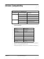
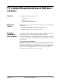
ERL 61850 IED
Configurator
User Manual
Version 2.0 Rev 1
Preface
Information in this document is subject to change without notice.
© 2015 ERLPhase Power Technologies Ltd. All rights reserved.
Reproduction in any manner whatsoever without the written permission of
ERLPhase Power Technologies Ltd. is strictly forbidden.
This manual is part of a complete set of product documentation that includes
detailed drawings and operation. Users should evaluate the information in the
context of the complete set of product documentation and their particular
applications. ERLPhase assumes no liability for any incidental, indirect or
consequential damages arising from the use of this documentation.
While all information presented is believed to be reliable and in accordance
with accepted engineering practices, ERLPhase makes no warranties as to the
completeness of the information.
All trademarks used in association with B-PRO, B-PRO Multi Busbar, Multi
Busbar Protection, F-PRO, iTMU, L-PRO, ProLogic, S-PRO, T-PRO,
TESLA, I/O Expansion Module, TESLA Control Panel, Relay Control Panel,
RecordGraph and RecordBase are trademarks of ERLPhase Power
Technologies Ltd.
Windows® is a registered trademark of the Microsoft Corporation.
HyperTerminal® is a registered trademark of Hilgraeve.
Modbus® is a registered trademark of Modicon.
Contact Information
ERLPhase Power Technologies Ltd.
74 Scurfield Blvd.
Winnipeg, Manitoba, Canada
R3Y 1G4
Website: www.erlphase.com
Email: [email protected]
Technical Support
Email: [email protected]
Tel: 1-204-477-0591
D03561R02.01
ERL 61850 IED Configurator Tool
i
Using This Guide
This user manual describes the installation and operation of the ERL 61850
IED Configuration Tool user interface software. It is intended to support the
first time user and clarify the details of the equipment.
The manual uses a number of conventions to denote special information:
Example
Describes
Start>Settings>Control Panel
Choose the Control Panel submenu in the Settings submenu on the Start menu.
Right-click
Click the right mouse button.
Recordings
Menu items and tabs are shown in italics.
service
User input or keystrokes are shown in bold.
Text boxes similar to this one
Relates important notes and information.
..
Indicates more screens.
Indicates further drop-down menu, click to display list.
Indicates a warning.
D03561R02.01
ERL 61850 IED Configurator Tool
iii
Table of Contents
Preface ......................................................................................i
Contact Information ...................................................................i
Using This Guide ..................................................................... iii
Table of Contents .....................................................................v
Version Compatibility .............................................................. vii
PC System Requirements and Software Installation ............... ix
1 Chapter System Overview..................................... 1-1
Introduction ...................................................................... 1-1
Definitions ........................................................................ 1-2
Features........................................................................... 1-3
2 Project Editor.......................................................... 2-1
Create a Project ............................................................... 2-1
Adding IEDs ..................................................................... 2-2
Other IED Functions ........................................................ 2-3
3 Configurations Editor ............................................ 3-1
Properties......................................................................... 3-1
Goose Mapping................................................................ 3-2
Data Mapping................................................................... 3-3
Subscriber Display ........................................................... 3-5
Sampled Value Control Blocks Configuration .................. 3-6
GOOSE Control Blocks Configuration ............................ 3-9
Sampled Value Mapping................................................ 3-12
Report Control Blocks Configuration.............................. 3-15
Datasets Configuration .................................................. 3-19
StartUp cfg File Details .................................................. 3-21
4 IED Palette .............................................................. 4-1
5 Output Window....................................................... 5-1
6 File Menu................................................................. 6-1
Overview .......................................................................... 6-1
Download from Other Vendor's Device............................ 6-2
Export CID ....................................................................... 6-4
View GOOSE Mapping .................................................... 6-4
Recent Projects................................................................ 6-6
D03561R02.01
ERL 61850 IED Configurator Tool
v
Table of Contents
7 Settings ................................................................... 7-1
vi
ERL 61850 IED Configurator Tool
D03561R02.01
Version Compatibility
IED Configuration Tool Compatibility Guide
Configurator Version
Compatible ICD File Versions
Added Feature
v2.0
00, 1.0
Generic GOOSE Subscription
2.0
Control Blocks/ dataset editing
2.1
VLAN Handling
3.0
Sample Value with Generic Subscription
00, 1.0
Generic GOOSE Subscription
2.0
GOCB/RCB/Dataset Editing
2.1
VLAN Support
v1.0
Products Supported
Product
Firmware Version
B-PRO 4000
v2.0a or greater
B-PRO Multibus
v1.0 or greater
F-PRO 2000
v1.0 or greater
F-PRO 4000
v1.0 or greater
I/O Expansion
v1.0 or greater
L-PRO 4000
v2.1a or greater
S-PRO 4001
v2.0 or greater
TESLA 4000
v1.3 or greater
T-PRO 4000
v1.0 or greater
Note: refer to the version compatibility table in the product user manuals for
ICD file version by each Firmware version.
Please contact ERLPhase Customer Service for complete Revision History.
D03561R02.01
ERL 61850 IED Configurator Tool
vii
PC System Requirements and Software
Installation
Hardware
The minimum hardware requirements are:
• 1 GHz processor
• 2 GB RAM
• 20 GB available hard disk space
Operating
System
The following software must be installed and functional prior to installing the
applications:
• Microsoft Windows XP Professional Service Pack 3 or
• Microsoft Windows 7 Professional Service Pack 1
To Install
Software on
your Computer
To install the software on the computer, go to http://www.erlphase.com/support.php?ID=software and select ERL 61850 IED Configurator.
To view the Configurator User Manual the user must have Adobe Acrobat on
the computer. If a copy is needed, download a copy by clicking on Download
Adobe Acrobat.
Anti-virus/Anti-spyware Software
If an anti-virus/anti-spyware software on your local system identifies any of
the ERLPhase applications as a “potential threat”, it will be necessary to configure your anti-virus/anti-software to classify it as “safe” for its proper operation. Please consult the appropriate anti-virus/anti-spyware software
documentation to determine the relevant procedure.
D03561R02.01
ERL 61850 IED Configurator Tool
ix
1 Chapter System Overview
1.1 Introduction
The ERL 61850 IED Configurator is used to configure ERLPhase IEC 61850
based devices for substation automation. This tool helps the user to map data
from remote GOOSE into ERLPhase IED data.
SCL is used for the configuration of electrical substation IEDs (61850-6 and
IEC 61850-7-x ).
It does the interoperable exchange of communication system configuration
data between an IED configuration tool and a system configuration tool. The
configuration language is based on the Extensible Markup Language (XML)
version 1.0.
Figure 1.1: ERL 61850 IED Configurator
D03561R02.01
ERL 61850 IED Configurator Tool
1-1
1 Chapter System Overview
1.2 Definitions
Definitions of substation terminology:
1. IED – a substation automation device performing functions by means of
logical nodes (LNs)
2. Server – a communication entity within an IED
3. LDevice – Logical Device, contained in a server of an IED
4. LNode – Logical Node, contained in a logical device of an IED
5. DO – the DATA contained in the LNs
SCL File Types:
ICD – IED Capability Description
Data exchange from the IED configuration tool to the system configuration tool
SSD – Substation Specification Description
Data exchange from a system specification tool to the system configuration tool
SCD – Substation Configuration Description
Data exchange from the system configuration tool to IED configuration
tools
CID – Configured IED Description
Data exchange from the IED configuration tool to the IED
1-2
ERL 61850 IED Configurator Tool
D03561R02.01
1 Chapter System Overview
1.3 Features
Figure 1.2: SCL File Types and Relations
ERL 61850 IED Configurator GUI has a split based window layout. The Configurator can create, edit and save projects. The project can be opened and edited in the Configurator and is saved as a binary file with a unique extension.
Files with this extension can be opened and edited in the Configurator. Windows can be resized for convenience.
D03561R02.01
ERL 61850 IED Configurator Tool
1-3
1 Chapter System Overview
Figure 1.3: Configurator Screen
The Configurator screen is divided into four parts.
Table 1.1: Configurator Screen
1-4
Project Editor
Project Editor lists all the local and remote IEDs
Configurations Editor
It contains IED Properties editor, GOOSE config, IED
Configuration, Startup properties editor
IED Palette
IED Palette stores and displays ERL Phase IED templates and other imported templates
OutPut Window
It displays history of events and error for the present
project
ERL 61850 IED Configurator Tool
D03561R02.01
2 Project Editor
Project Editor lists all the local and remote IEDs added for a project created in
the Configurator. A new project in Configurator opens an empty project editor.
Figure 2.1: Project Editor
IEDs can be added to the project by dragging and dropping an IED from the
IED Palette.
After you add a new IED, the configuration tool displays an icon representing
the new IED in the Project Editor.
2.1 Create a Project
You can start a new project using the menu File>New Project, key board short
cut Ctrl+N or from the tool bar.
Figure 2.2: Create a New Project
D03561R02.01
ERL 61850 IED Configurator Tool
2-1
2 Project Editor
2.2 Adding IEDs
You can add IEDs to the project by dragging IED product from the IED palette
and dropping it into the project editor. After dropping into project editor the
user is asked to select the IED as shown below.
Figure 2.3: Add IED to Project
The user can select the desired IED version and enter the instance name and
click OK to finish the process . Now the newly added IED is shown in the project editor. If the manufacturer of the IED is ERLPhase, it is added under the
node Local IEDs, otherwise it is added under the node Remote Publisher. The
user can distinguish between Local IEDs and Remote Publisher by the different icons.
Figure 2.4: Project Editor
2-2
ERL 61850 IED Configurator Tool
D03561R02.01
2 Project Editor
2.3 Other IED Functions
The user can delete an IED from the project (note that if any GOOSE elements
are used for GOOSE subscription mapping delete request will be rejected), renaming an IED in the project, sending the CID file to the ERL device, downloading CID file from the ERL device, downloading ICD file from the ERL
device, viewing the log file of IEC61850 application in the ERL device. (All
operations of sending or downloading to/from the device will be using the IP
Address configured in the IED Properties window).
Figure 2.5: Functions Available
The functionalities other than Delete IED and Rename IED are not available
for Remote Publishers (Non ERL) and ERL IEDs of unrecognized file versions.
D03561R02.01
ERL 61850 IED Configurator Tool
2-3
2 Project Editor
Figure 2.6: Functions are not available for the remote non ERLPhase IEDs
2-4
ERL 61850 IED Configurator Tool
D03561R02.01
3 Configurations Editor
3.1 Properties
Each IED added to a project has a set of properties. These include Name, Type,
Manufacturer, Description, etc.
Figure 3.1: IED Properties setup screen
The IP Address indicates the IP Address of ERL IED. All ftp related operations
of an IED will be refer to this address.
D03561R02.01
ERL 61850 IED Configurator Tool
3-1
3 Configurations Editor
3.2 Goose Mapping
This configuration screen allows the user to map the desired data from the
GOOSE publication to 61850 inputs of the selected IED in the project editor.
Figure 3.2: GOOSE Config
In the GOOSE Publication section the display is in the following format
Level1 – <IEDName>
Level2 – <LogicalDeviceName>.<GOOSE Name>
Level3 – <Dataset>
Level4 – <LogicalDeviceName>/<FCDA>
FCDA: Functionally Constraint Data Attribute
In the GOOSE Subscription-Mapping section the list view displays data items from the logicaldevice VirtualElements (GGIO2->ST->Ind1->stVal
to
GGIO2->ST->Ind30->stVal) for Non-TESLA IEDs and data items from logicaldevices PhasorExtRcdTriggers(GGIO1->ST->Ind1->stVal to GGIO1>ST->Ind64->stVal) and SVExtRcdTriggers(GGIO1->ST->Ind1->stVal to
GGIO1->ST->Ind64->stVal) for TESLA IEDs
3-2
ERL 61850 IED Configurator Tool
D03561R02.01
3 Configurations Editor
Note: In addition to the above subscription points all BOOLEAN elements in any logical node of lnClass = ”GGIO” and prefix = ”SUBSCR” will also be listed as subscription points.
3.3 Data Mapping
The user can browse through the GOOSE publication to identify the desired
data item then drag it and drop on the desired 61850 input on the GOOSE Subscription Mapping section.
Figure 3.3: Data Mapping
The user can remove the mapping of a data item by right clicking the mapped
data item and using the function Remove Mapping.
D03561R02.01
ERL 61850 IED Configurator Tool
3-3
3 Configurations Editor
Figure 3.4: Remove a Mapping from the list by right clicking on selected items
3-4
ERL 61850 IED Configurator Tool
D03561R02.01
3 Configurations Editor
3.4 Subscriber Display
Figure 3.5: Subscriber Display
In Subscriber section Logical Node drop down lists the logical nodes predefined for subscription in the selected IED in project editor. According to the
selection of logical node available BOOLEAN data items (in fc ST) will be
listed in GOOSE subscription section .
The user can see the data path of a VI (e.g. VI03 in below shown screen) in tool
tip by clicking on the GOOSE IN item.
Figure 3.6: Tool tip will be shown when clicking on the GOOSE IN item
D03561R02.01
ERL 61850 IED Configurator Tool
3-5
3 Configurations Editor
3.5 Sampled Value Control Blocks Configuration
This displays the Sampled Value control blocks' details. The publisher part
shows the Sampled Value control blocks details in the selected IED in project
editor.
The Subscriber part shows the incoming Sampled Value (Mapped Sampled
Value) details for the selected IED.
Figure 3.7: Sampled Value control block screen
Note: Disabled Sampled Value control blocks will be grayed out in the
list.
Using the check box in the list the user shall disable or enable the Sampled Value control block
Adding a
Sampled Value
Control Block
Click on the Add button in the Sampled Value Control Blocks Configuration
screen which will display the screen shown below from which the user has to
select the logical device to which Sampled Value control block has to be added.
Figure 3.8: Select Logical Device
3-6
ERL 61850 IED Configurator Tool
D03561R02.01
3 Configurations Editor
After selecting the logical device click Ok button which will display the below
shown screen.
Figure 3.9: New Sampled Value Control Block
The user can enter the Sampled Value details in this screen and click OK button. (Note that duplicate Sampled Value name is not allowed in the same logical device and the dataset drop down list contains datasets in the selected
logical device).
Editing a
Sampled Value
Control Block
D03561R02.01
Select the Sampled Value Control Block from Sampled Value Control Block
Configuration screen. Now either double clicking on the selected Sampled
Value or clicking Edit button will display the Edit Sampled Value screen
where the user can edit the Sampled Value details.
ERL 61850 IED Configurator Tool
3-7
3 Configurations Editor
Deleting a
Sampled Value
Control Block
Select the Sampled Value Control Block from Sampled Value Control Block
Configuration screen and click on delete button.
Note: If the selected Sampled Value Control Block is used for mapping purpose in other IEDs the delete request will be rejected .
Editing
Subscriber SMV
The subscriber section of Sampled Value Control Block Configuration screen
contains all the Sampled Value mapped to the selected IED. The user can edit
the MAC-Address of the selected Subscriber Sampled Value by either double
clicking on the subscriber goose or using Edit button
Figure 3.10: Edit MAC address
3-8
ERL 61850 IED Configurator Tool
D03561R02.01
3 Configurations Editor
3.6 GOOSE Control Blocks Configuration
This displays the GOOSE control blocks’s details. The publisher part shows
the GOOSE control blocks details in the selected IED in project editor.
The Subscriber part shows the incoming GOOSE (Mapped GOOSE) details
for the selected IED.
Figure 3.11: GOOSE Control Block configuration summary screen
Note: Disabled GOOSE control blocks will be grayed out in the list.
Using the check box in the list the user shall disable or enable the GOOSE control block.
D03561R02.01
ERL 61850 IED Configurator Tool
3-9
3 Configurations Editor
Adding a
GOOSE Control
Block
Click on the Add button in the GOOSE Control Blocks Configuration screen
which displays the screen shown below from which the user has to select the
logical device to which GOOSE control block has to be added.
Figure 3.12: Add GOOSE Control Blocks
After selecting the logical device click OK button which will display the below
shown screen
Figure 3.13: Enter GOOSE Details
The user can enter the GOOSE details in this screen and click OK button. (Note
that duplicate GOOSE name is not allowed in the same logical device and the
dataset drop down list contains datasets in the selected logical device).
Note : If the IED version supports VLAN management and Min/Max
Time config VLAN ID,VLAN Priority, Min Time and Max Time will be
enabled.
3-10
ERL 61850 IED Configurator Tool
D03561R02.01
3 Configurations Editor
Please find the min, max limits for the parameters below.
Table 3.1: Parameters
Parameters
Min
Max
Config Revision
1
1000
MinTime
2 ms
10000 ms
Max Time
1000 ms
600000 ms
App ID
0000x
3FFFx
VLAN ID
000x
FFFx
Editing a
GOOSE Control
Block
Select the GOOSE Control Block from GOOSE Control Block Configuration
screen. Now either double clicking on the selected GOOSE or clicking Edit
button will display the Edit GOOSE screen where the user can edit the GOOSE
details.
Deleting a
GOOSE Control
Block
Select the GOOSE Control Block from GOOSE Control Block Configuration
screen and click on Delete button
Note: If the selected GOOSE Control Block is used for mapping purpose in
other IEDs the delete request will be rejected as shown below.
Figure 3.14: Deleting GOOSE Control Block
Editing
Subscriber
GOOSE
The subscriber section of GOOSE Control Block Configuration screen contains all the GOOSE mapped to the selected IED. The user can edit the MACAddress of the selected Subscriber GOOSE by either double-clicking on the
subscriber goose or using Edit button
Figure 3.15: Editing GOOSE Control Block
D03561R02.01
ERL 61850 IED Configurator Tool
3-11
3 Configurations Editor
3.7 Sampled Value Mapping
This configuration screen allows the user to map the desired data from Sampled value publication to 61850 inputs of the selected IED in the project editor.
Figure 3.16: Sample value mapping screen
In the Sampled Value Publication section the display is in the following format.
Level1 - <IEDName>
Level2-<LogicalDeviceName>.<GOOSE Name>
Level3 -<DataSet>
Level4 -<LogicalDeviceName>/<FCDA>
FCDA: Functionally Constraint Data Attribute
In the SMV Subscription-Mapping section the listview displays FLOAT32
data items from logical node of lnClass="GGIO" and prefix="SUBSVA" will
also be listed as subscription points.
3-12
ERL 61850 IED Configurator Tool
D03561R02.01
3 Configurations Editor
Data Mapping
The user can browse through the SMV publication to identify the desired data
item then drag it and drop on the desired 61850 input on the SMV Subscription
Mapping section.
Figure 3.17: Sample value mapping
The user can remove the mapping of a dataitem by right clicking the mapped
data item and using the function Remove Mapping
D03561R02.01
ERL 61850 IED Configurator Tool
3-13
3 Configurations Editor
Figure 3.18: Removing Sample Value Mapping
3-14
ERL 61850 IED Configurator Tool
D03561R02.01
3 Configurations Editor
3.8 Report Control Blocks Configuration
This screen shows the buffered and unbuffered reports of the selected IED.
This also allows the user to add, edit and delete Report Control Blocks.
Figure 3.19: Report Control Block Config
Note: Disabled report control blocks will be grayed out in the tree
view.
Using the check box in the list the user shall disable or enable the report control
block.
D03561R02.01
ERL 61850 IED Configurator Tool
3-15
3 Configurations Editor
Adding a
Report Control
Block
To add a Report Control Block click on Add button. It will display the below
shown screen.
Figure 3.20: Adding a Report Control Block
The user can enter the Report Control Block details in this screen. The user can
select to which logical device report control block has to be added. Datasets
from the LLN0 of selected the logical device will be listed in the dataset drop
down. After entering the details the user has to click OK button. Please note
that the Report Control Block is created in LLN0 of logical device.
3-16
ERL 61850 IED Configurator Tool
D03561R02.01
3 Configurations Editor
Please find the min, max limits for the parameters below.
Table 3.2: Setting Parameters and Corresponding Setting Ranges
Parameters
Min
Max
Buffer Time
0 ms
3600000 ms
Integrity Period
0 ms
1800000 ms
Number of Instances
1
16
Editing a Report
Control Block
Select the Report Control Block from Report Control Block Configuration
screen. Now either double-clicking on the selected Report Control Block or
clicking Edit button displays the Edit RCB screen where the user can edit the
Report control block details.
Deleting a
Report Control
Block
Select the Report Control Block from Report Control Block Configuration
screen and click on Delete button. The user will be asked to confirm the action.
Printing Report
Control Blocks
information
The user can print report control blocks information using the Print button.
Bitstring
Format for
Displaying RCB
Options Fields
and Trigger
Options
In IED Configurator the RCB Options fields are displayed in bitstring format
as shown below
Figure 3.21: RCB Options Fields
RCB Options Fields are displayed in the following order of bits.
Table 3.3: Options Fields Bits Description
D03561R02.01
ACSI Value of BRC State
MMS Bit Position
reserved
0
sequence-number
1
report-time-stamp
2
reason-for-inclusion
3
ERL 61850 IED Configurator Tool
3-17
3 Configurations Editor
Table 3.3: Options Fields Bits Description
ACSI Value of BRC State
MMS Bit Position
data-set-name
4
data-reference
5
buffer-overflow
6
entryID
7
conf-revision
8
segmentation
9
RCB Trigger options are displayed in the following order of bits:
Table 3.4: Trigger Options
3-18
Bit 0
reserved (reserved to provide backward compatibility with UCA 2.0)
Bit 1
data-change
Bit 2
quality-change
Bit 3
data-update
Bit 4
integrity
Bit 5
general-interrogation
ERL 61850 IED Configurator Tool
D03561R02.01
3 Configurations Editor
3.9 Datasets Configuration
This configuration screen displays all the datasets in a list, IED Data Items of
the selected IED and the dataset items of the selected dataset.
Figure 3.22: Datasets Configuration
The capacity meter for GOOSE and RCB display the capacity of the dataset for
GOOSE and RCB.
Adding a
Dataset
The user can add a new dataset by clicking on Add button. It will display a
screen as shown below.
Figure 3.23: Adding a Dataset
D03561R02.01
ERL 61850 IED Configurator Tool
3-19
3 Configurations Editor
The user can enter the dataset details and click the OK button, then the data set
is added to the selected logical node (logical node is fixed as LLN0) in selected
logical device. (Note that while adding the dataset user is not selecting the data
items (FCDA/FCD) for the dataset. This can be later configured from the Datasets Configuration screen).
Editing/
Configuring a
Dataset
The user can select the dataset to be edited from the list.
Deleting a
Dataset
The user can select the desired dataset from the list and click on Delete button.
The user will be asked to confirm the action.
Dataset Items (FCDA/FCD) section shows the data items present in the selected dataset. IED Data Items shows the Logical devices and logical nodes in the
logical device. The user can select the desired data object or data attribute from
the logical node and drag it and drop in the Dataset Items (FCDA/FCD) section.
If the dataset it referenced by a GOOSE control block or Report Control Block
it can not be deleted. dataset.
Figure 3.24: Deleting a Dataset
Cloning a
Dataset
This functionality is for creating a dataset from an existing dataset. The user
can select the desired dataset from the drop down list to be cloned and click on
Clone button. The user can see the below shown screen in which the user can
enter the dataset name and description.
Figure 3.25: Cloning a Datase
3-20
ERL 61850 IED Configurator Tool
D03561R02.01
3 Configurations Editor
3.10 StartUp cfg File Details
This screen displays all the Startup Configuration details of the selected IED.
Figure 3.26: StartUp cfg File Details
Table 3.5: StartUp Parameters Description
D03561R02.01
Parameter
Description
SCLFileName
Name of SCL(CID) File to be parsed by IEC61850 application
IEDName
Name of IED to be parsed by IEC61850 application
from SCL(CID) File
AccessPointName
Access point information to IEC61850 application
ReportLog Scan Rate (milliseconds)
Internal Data Scan Rate for the generation of Reports
based on data changes
Report BufferSize (bytes)
Circular Buffer allocated for storing buffered reports in
IEC61850 application
NetworkCardID
NetworkCardID
IPAddress
IPAddress
MAX_CALLED_CONNECTIONS
Maximum number of client connections that can be
accepted by IED
MAX_DYNAMIC_TYPES
Buffer allocated for storing data types. Configuration file
parsing will fail if maximum limit is reached
MAX_LN_VARS
Buffer allocated for storing variables inside a logical
Node. Configuration file parsing will fail if maximum limit
is reached
MAX_NUM_DATASETS
Buffer allocated for storing datasets. Configuration file
parsing will fail if maximum limit is reached
ERL 61850 IED Configurator Tool
3-21
3 Configurations Editor
Table 3.5: StartUp Parameters Description
3-22
MAX_PDU_SIZE (bytes)
Maximum Size of MMS Packets; Data exchange with
IEC61850 Client will use this parameter
MAX LOG FILE SIZE (KBs)
Maximum Size of the Circular Log file
LogLevel
Logging mode of IEC61850 application while running
MAX_NUM_DS_VARS
Buffer allocated for storing dataset variables of a subscribed GOOSE. Configuration file parsing will fail if
maximum limit is reached
MAX_SUB_GOOSE
Buffer allocated for storing subscribed GOOSE information, Configuration file parsing will fail if maximum limit is
reached
ERL 61850 IED Configurator Tool
D03561R02.01
4 IED Palette
IED Palette stores and displays ERL Phase IED templates as well as other remote IEDs. ICD files are allowed to import as templates. ERL IED files are categorized by their product name.
Figure 4.1: IED Palette
IED product contains different versions of IED files.
e.g. B-PRO 4000 product contains IED files of version 1.0 and 2.0.
The user can import new IED template to IED Palette using the functionality
Import IED. The user gets the below shown menu when right-clicking on the
IED Palette.
Figure 4.2: Import IED
The user can browse the desired ICD, CID or SCD file to be added to the IED
Palette.
D03561R02.01
ERL 61850 IED Configurator Tool
4-1
4 IED Palette
Figure 4.3: Browse Files
If the user is trying to add a ERL IED file the below shown screen appears to
display the Product Type and ICD File Version of the selected file.
Figure 4.4: IED File Details
Please note that this information is read from the selected IED file.
Once the user clicks OK this IED file is added to product B-PRO 4000. Please
note that if any IED file with ICD file version exists in the product, the user has
to confirm the action.
4-2
ERL 61850 IED Configurator Tool
D03561R02.01
5 Output Window
This window shows the different Informations and errors related to IED Configurator.
Figure 5.1: Output Window
D03561R02.01
ERL 61850 IED Configurator Tool
5-1
6 File Menu
6.1 Overview
Select File from the Menu Bar to obtain a drop-down listing similar to the following.
Figure 6.1: File Menu
Table 6.1: File Menu
D03561R02.01
New
Creates a New Project.
Open
Opens a project.
Save
Saves the project.
Save As
Save as the project.
Import IED into Palette:
Imports a ICD/CID file to IED Palette.
Verify ICD
This option is for validating the original file of IED in the
project editor against the SCL schema.
Verify CID
This option is for validating an IED file with all configurations done using IED Configurator against the SCL
schema. If the validation is successful user gets a message Scheme Validation Successful. Otherwise user will
get a window where all errors are listed as show below.
ERL 61850 IED Configurator Tool
6-1
6 File Menu
Figure 6.2: Verify CID
6.2 Download from Other Vendor's Device
This option is for connecting to any FTP enabled IED device and download required files from the device. By entering a valid FTP address, user name and
password you can connect to any IED device other than ERLPhase device.
After clicking Next the IED Configurator tries to connect to the desired FTP
Location. If not possible user gets a proper message.
Figure 6.3: Download from Other Vendor's Device
If IED Configurator is successfully connected to the IED device, the user can
see the browser window. Once the user expands the root node, the Configurator retrieves the directories inside the root and loads to the tree view
If the user selects a directory node, the files inside the directory are
listed on the right side list view
6-2
ERL 61850 IED Configurator Tool
D03561R02.01
6 File Menu
Figure 6.4: Example: Files shown in the remote IED through ftp tool provided by the
configurator
From the listview of files the user can select the file and download to a local
system using the Download from Device (right click menu) functionality. The
user will be asked for the path where the downloaded file to be saved.
Figure 6.5: Downloading the selected file
The user can see the downloading progress just below the listview of files.
D03561R02.01
ERL 61850 IED Configurator Tool
6-3
6 File Menu
6.3 Export CID
This option is for exporting the selected IED in project editor to CID file with
GOOSE Subscription (mapping) information and IED configuration information.
6.4 View GOOSE Mapping
This functionality allows the user to connect to an IED selected in the project
editor. By default this will connect to the IP Address present in the IED properties
Figure 6.6: Configurator retrieves the mapping information from the ERLPhase IED
Once the cid file is retrieved from the IED, the mapping present in the cid file
will be shown as below
6-4
ERL 61850 IED Configurator Tool
D03561R02.01
6 File Menu
Figure 6.7: View GOOSE Mapping screen
D03561R02.01
ERL 61850 IED Configurator Tool
6-5
6 File Menu
6.5 Recent Projects
This shows the recently opened IED Configurator project files.
Edit:
Edit contains undo and redo functions.
Figure 6.8: Undo and Redo function for error correction
Undo/Redo is available for following operations of IED Configurator:
• Adding a IED to project
• Deleting a IED from project
• IED instance renaming in project editor.
• GOOSE subscription mapping
• GOOSE subscription mapping removal
• GOOSE control block Add, Edit, Delete
• Report control block Add, Edit, Delete
• Dataset Add, Edit/Configure, Delete
6-6
ERL 61850 IED Configurator Tool
D03561R02.01
7 Settings
Change
Password
This functionality allows the user to change the login password for
ERLPhase IED Configurator. The default password is ERLConfigTool.
Figure 7.1: Change password under Settings
D03561R02.01
ERL 61850 IED Configurator Tool
7-1