1
Team Duck Hunt
Ravi Raghavan
AJ Setto
Dennis Ting
Page 1 of 27
Table of Contents
Design Repository Location
3
What is Duck Hunt?
4
Overall Design Description
5
Final software/hardware description
9
What we learned
22
Individual pages
24
Citations
27
Page 2 of 27
Design Repository
We have placed all the source code of Duck Hunt in Duck_Repository.zip. It contains
the Xilinx Platform Studio (XPS) folder that allows us to download the code to the Virtex
V board and run Duck Hunt. It also contains the GlovePie script we wrote for the
Wiimote, the Java code we wrote for the serial connection, the necessary Java comm.jar
library, our progress on the direct USB approach, and useful documentation for those
who try this approach in the future. To get the Duck Hunt program working, simply open
the .xmp file inside the DuckHuntGame folder. To see our progress on USB, open the
.xmp file in the USBProject folder.
The Duck_Repository.zip file has been uploaded to Blackboard. It contains all the source
code of our project. Also, we uploaded the XPS project folder to AFS, located at
/afs/andrew.cmu.edu/usr16/dennist/public/18545/DuckHunt
Page 3 of 27
What is Duck Hunt?
We implemented an old Nintendo game called Duck Hunt onto a Virtex 5 board.
Our implementation of Duck Hunt includes external user input (from keyboard and
Wiimote), video, scoring, and multiplayer capabilities. The one twist to the Duck Hunt
game that we will be implementing is making use of the new Bluetooth Technology of
the Wiimote.
The Duck Hunt Game is one of the most popular games when we were growing
up. It has been duplicated online in flash and many other languages. We considered
porting an existing implementation of Duck Hunt over to the FPGA. We found many
implementations of Duck Hunt, but all of them were unsuitable for our purposes. Some
were written in languages that were unavailable on the Virtex V (e.g. Java, C#, Perl,
Flash). Others were unprofessional or unfaithful to the original NES game. Thus, we
made the decision to rewrite the game from scratch, choosing only to borrow the Duck
Hunt sprites from Internet sources. Bluetooth technology is an amazing technology to
use, but it was very challenging to implement.
The objective of the game Duck Hunt is to shoot as many ducks down as possible
without them flying away. Each player is only given 3 shots per 1 or 2 ducks, depending
on which mode is chosen. In the original multiplayer version, the 1 st player would be
given 10 ducks sequentially to shoot down. The 2nd player then goes to see if he can
outdo his competitor. In our version, we modified this feature and have 2 players play
simultaneously. One player controls the duck and flies around while the other player tries
to shoot him down.
Our group showed dedication and cooperation in finishing this project on time
while meeting most of the specifications.
Page 4 of 27
Design Process
Our first step in this software project was to come up with a feasible idea.
Initially, there were six of us with no definite grouping. The six of us bounced ideas back
and forth till two ideas were formed. One of the ideas was to build the GameBoy Color
and the other was reproducing the classic game of Duck Hunt. Half of us took a liking to
the Duck Hunt idea with Wiimote and thus the groups were formed.
Initially, we started the class by researching what it would take to get this project
to work. We studied the success and failures of the previous Xilroids group in order to
get an idea of what their main challenges were. We immediately realized that the bulk of
the project work was going to be getting the USB port to work. We planned for this
difficulty by deciding to have one group member constantly focused on USB from the
start. We also planned to finish a faithful reproduction of Duck Hunt as soon as possible,
finishing it before mid-semester break. We were dedicated to this schedule and
successfully created an almost complete version of Duck Hunt and finishing all the labs
before mid-semester, leaving the rest of the time to get the USB working.
In the early weeks, we did a lot of research into finding a dedicated port of the
game. This turned out to be a dead-end as there were no faithful ports in C. We decided
that with our strong programming backgrounds we could successfully reproduce the
game even better than the ones on the Internet. This turned out to be a great decision on
the team’s part. Our implementation of Duck Hunt is, in our opinion, better than any of
the ones we discovered on the Internet. One of our group members in the meantime
already started dedicating time to researching USB to figure out what we needed to do to
successfully communicate with it. This also was a very good decision, because we were
able to jump right into USB immediately after the faithful port was created.
The initial weeks came along without a hitch on the Virtex II. We had sound,
video, and a PS/2 mouse working successfully and the game was very playable. The USB
was looking very difficult to implement on the Virtex II judging from previous projects
as well as forums on the Internet. Then, the option of the Virtex V was given to us by
Professor Nace. This seemed like a blessing from the sky at first because of the fact that it
had a USB port on the board itself unlike the Virtex II. We decided after very careful
deliberation to switch due to the fact that getting the USB working with Wiimote was our
main priority in the project. This is when the difficulty of our project rapidly increased.
The first difficulty that we ran into was that the Virtex V was not backwards
compatible with the Virtex II. Our initial problem was that the Xilinx sample code for
video and USB both did not synthesize together or separately. This was primarily due to
the lack of documentation and hidden bugs in the Xilinx code. After we fixed up some of
the syntax and memory issues that Xilinx had in their code, we still were running into
problems with Generating Addresses as well as synthesizing. We finally were able to
synthesize their video demo code after 2 weeks. This was the first hurdle we had to cross
but it soon led to another problem. When we incorporated USB with the video code,
hidden errors would pop up. The sample code was written for an earlier version of Xilinx
Platform Studio and EDK, and some parts were not backwards compatible.
Page 5 of 27
There were two major but sneaky problems with the Xilinx implementation. The
first was that there were conflicting pins in the Xilinx code with compactFlash and USB.
When synthesizing, the Xilinx program would automatically realize that there are
conflicting pins, and remove one of them without throwing an error. Then at the end of
synthesis, it would error saying that the pin was not there. We had problems
understanding why the pin wasn’t being recognized considering we saw it in the file
declared. We finally had to go through all 200 warnings and realize that Xilinx was
removing the pin without declaring it as an error. We then disabled compactFlash, and it
finally synthesized with no bugs. We then had to fix the 2 nd problem which was more
conflicting pins, but since we knew about the previous error, debugging these were a lot
easier. In the end, it took us about 3.5 weeks to just transfer over our existing code from
the Virtex II to the Virtex V. In the end, these 3.5 were very costly to our overall project,
because we went from being on schedule to behind schedule. We thought we could make
up for this time, because USB would be easier to implement, but we soon realized that
this was a flawed assessment of the situation, because USB was much more difficult than
anyone could imagine.
With the USB demo, we got a working implementation of the USB keyboard with
the FPGA. This, however, proved to be very useless in the end. This was due to the fact
that we were given the keyboard driver in binary and were not given the actual source
code. We contacted both Xilinx and Cypress multiple times to no avail. (Cypress makes
the actual USB chip found on the Virtex V.) We also searched online and on forums in
order to find out where the source code could be found. However, there is no
documentation of it anywhere online. There were others with the same types of questions
on the forums, but they received no answers as well.
We now had to decide on which way we should progress on our project. There
were multiple options we could do for the USB controller. The first option was to
attempt to get Linux running on the microblaze processor. In theory, this would allow us
to use the Linux USB and Bluetooth drivers so that we would not have to write our own.
However, the only versions of Linux that we could get working on any Virtex board
required that we have an on-board PowerPC processor. Since our board only had the soft
microblaze core, we could find no usable Linux implementation. Also, even if we did get
Linux running on our board, we would still need to find a driver that could interface with
either the external Cypress USB controller or an internal synthesized USB controller. We
were unsuccessful in our search for such drivers.
Another USB option was to establish communication between the FPGA and the
Cypress CY7C67300 Embedded Host Controller through writing and compiling our own
driver in binary, then loading the binary onto the controller via a C program written for
the FPGA. We were able to find a software development kit that at first seemed perfect
for compiling the code for the controller (at http://www.cypress.com/?rID=14436), but all
of the documentation assumed that we had the development package that could only be
ordered directly from Cypress. This package included its own main board and special
mezzanine attachment. There was no documentation from Cypress, Xilinx, or Digilent
that even mentioned such an approach for an FPGA. We decided it was worth an attempt
anyway, so we tried to adapt the documentation and examples to our environment and
Page 6 of 27
create our own keyboard driver that worked as well as the one included by Xilinx. We
wrote and compiled a simple program that wrote a single value to memory, and then we
checked it with the FPGA code. After dozens of attempts, we were unable to get a
successful response; it seemed that the code was not even beginning to run. Also, we had
no clues as to where our errors were or why it was not working. While this approach
seemed feasible at first, a lack of proper documentation and debugging support made it
impossible.
A third option that became apparent while looking through documentation was to
use a driver written for the FPGA instead of for the Cypress controller. This code would
run on the FPGA but have access to almost all of the controller’s internal registers
through an interface called HPI (Host Processor Interface). We could theoretically do the
same things that a driver running on the controller could but not have to worry about
compiling a separate program. We made most of our progress using this new approach.
A BIOS automatically runs on the controller and constantly watches for certain register
reads and writes; when those key registers change, the BIOS carries out predetermined
commands as specified in the Cypress BIOS User’s Manual. We were able to use this to
perform some simple communication with a keyboard, a mouse, and a USB Bluetooth
dongle. We could issue a USB reset to a device, detect if a device was plugged in, detect
the speed of the device (either low or full speed, the controller does not support high
speed), and read some built-in descriptors that supply details about the device. However,
there were two important limitations. We could only issue control transfers (only 1 of 4
possible types), and we could only issue one command per frame (1 ms). We tried with
all of our time and resources to find out how to set up different types of transfers and
send multiple linked transfers in one frame, but we were ultimately unsuccessful. In the
end, there was simply no documentation by Cypress that told us how to do anything
except a once-per-frame control transfer. Since everything we wrote was being carefully
coordinated by the Cypress BIOS, having no knowledge about the BIOS’ processes was
crippling to our progress.
When our project was looking more and more impossible by the day, a classmate
suggested that we synthesize our own USB controller using a pre-built Xilinx IP core.
We spent a couple days attempting to get it to synthesize, but there were multiple errors
about unconnected pins and incompatible hardware. As we saw that most people in the
class were having similar problems with Xilinx hardware and getting nowhere, we
decided to drop this and continue down the previous path.
To recap, a couple weeks into the project, we reached the mid-semester design
review. At this design review, we had a good working implementation of Duck Hunt on
the Virtex V with the USB keyboard. We now had to try to figure out a way to
communicate over USB to a device other than a keyboard. This was our main and only
priority at this point. In the next 2 weeks after the design review, we spent a lot of time
trying the different avenues of USB to figure out which one would be the best. We had
the most success with using the Cypress controller’s HPI interface to communicate with
the USB device.
We persisted on this avenue for the rest of the semester until a week before the
assignment was due. We were only able to send out one transaction at this point per ms,
Page 7 of 27
which was not fast enough. We could only send control transfers, which was not
sufficient. We could recognize the Bluetooth device, but that was all. We then had to do
a workaround in order to get a final demo together. We decided to quickly route the
Bluetooth device through the computer and through the serial port in order to achieve
this. This workaround took us less than a day to produce considering the difficulty of this
is much less than that of an on-chip controller. We ran the Bluetooth Wiimote through a
custom program called GlovePie. We then ran the output of GlovePie through the Java
Comm library which we then piped in through serial to detect changes in the Wiimote.
We were very happy about the quick save to our project even though we didn’t
get the USB on-chip controller working. However, we did learn an abundance of
information on USB controllers and drivers in this lengthy process.
Page 8 of 27
Software/Hardware Specifications
On the software side, we wrote modular code to interact with each hardware component.
In particular, we had C code to interact with the video frame buffer, code that receives
input from the USB keyboard, and code that receives input from the Wiimote. Together,
they interact with the hardware to provide us with the necessary inputs and outputs.
Afterwards, we wrote code that actually implements the Duck Hunt game. This includes
a random number generator, collision detection, and finally, the game itself.
Video frame buffer: DH_video.h / DH_video.c
The video code takes care of the double buffering so that other modules can work
with an idealized view of the video output. In particular, we have a Sprite struct.
typedef struct SpriteStruct
{
// Location of top left pixel
// (default value: x = 0, y = 0)
int x;
int y;
// 0 = farthest
// (default value: z = 0)
int z;
int backgroundColor;
// An array of Bitmap pointers
// no default values
Bitmap* bitmap[5];
// Length of this array (1 to 5)
// default values: bitmapArrayLength = 1,
// currentBitmapNum = 0
int bitmapArrayLength;
int currentBitmapNum;
// 1 if sprite is still alive
// 0 is sprite is dead
// (dead sprites don't show up on screen)
// default value: isAlive = 1
int isAlive;
int spriteType;
} Sprite;
The Duck Hunt code works only with this Sprite struct. It creates sprites
representing the ducks, dog, and every other object on the screen. Thus, the video
code is responsible for drawing these sprites onto the screen.
Page 9 of 27
It turns out to be too costly to redraw the entire 640 x 480 screen each frame, so
the video code works with three separate layers:
1) Foreground (active) sprites
2) Static sprites
3) Background
The background is drawn very rarely, because it takes about half a second to draw
the entire screen. Once we draw the background, we add sprites onto the screen.
Each frame, the video code erases the previous frame’s sprites and redraws the
current frame’s sprites onto the screen. Thus, instead of drawing the entire screen
each frame, only the sprites are drawn, and the background remains unchanged.
Building on this idea, we also implemented static sprites, which are sprites that
rarely move. For instance, although the ducks and dog are constantly moving,
sprites that represent the score, round number, etc rarely change. Thus, they do
not need to be drawn every frame. (For instance, the score sprites only need to be
redrawn when a duck is shot down and the score is incremented.) Thus, static
sprites are redrawn only when requested, which further increases our frame rate.
Ultimately, we were able to consistently get >25 frames per second. Due to the
sprite system, the frame rate depends on the number and sizes of the active
sprites. Based on testing, the game only starts to lag when we have about 20
ducks on the screen. (Of course, the actual Duck Hunt game only has two ducks
at any given time.)
The Duck Hunt code interacts with the video code using functions that draw and
remove these sprites from the screen.
void
void
void
void
void
void
void
void
DH_video_initialize();
DH_video_initializeSprite(Sprite* sprite);
DH_video_setBackground(Sprite* background);
DH_video_addSprite(Sprite* sprite);
DH_video_removeSprite(Sprite* sprite);
DH_video_addStaticSprite(Sprite* sprite);
DH_video_clearStaticSprite(Sprite* sprite);
DH_video_display();
Page 10 of 27
Random Number Generator: DH_random.h / DH_random.c
void DH_random_initialize();
void DH_random_randomize(int i);
int DH_random_nextInt(int i);
int DH_random_nextBool();
This module contains three private variables.
1) int array[800]: A pre-computed array of 800 random integers
2) int index: An index into this array. 0 ≤ index < 800
3) int seed: A seed value.
This module implements a random number generator suitable for Duck Hunt.
initialize() initializes the RNG. randomize(seed) is used to set the
seed. nextInt(i) returns a random integer within [0,i). nextBool()
returns 0 or 1, each with 50% probability.
In Duck Hunt, we need two things from the random number generator:
1) A way to generate random numbers in order to simulate the ducks’ random
movements.
2) Some way to randomize the seed so that each game plays differently.
In Duck Hunt, the ducks fly around somewhat randomly. Their speed and
direction are determined randomly. The type of duck (green, blue, red) is also
determined randomly. Thus, a random number generator is necessary. However,
this random number generator does not need to be very mathematically robust. It
needs only be random enough for the user not to notice. For this reason, we chose
to simply pre-compute the random numbers that are used. We wrote a Java
program to fill the array[800] with random integers. When calling
nextInt(i), we return (0x7fff_ffff & (array[index] xor seed)) % i,
and index is then incremented.
The above method solves the first requirement; we now have random numbers.
However, since the numbers are pre-computed, we have not yet satisfied the
second requirement, which is that each game must play out differently. In other
words, we need some way to obtain a seed. In most RNG implementations, the
default seed is the current system time. Since the Virtex V does not have a
system time, we used the very similar notion of the number of frames elapsed. In
other words, the seed number is determined by how many frames have elapsed by
the time the user hits “start game.” This way, each game plays out differently.
Page 11 of 27
Keyboard input: DH_keyboard.h / DH_keyboard.c
void DH_keyboard_initialize();
int DH_keyboard_getRawInput();
This module interacts with the USB keyboard, allowing the Duck Hunt code to
receive keyboard input. The keyboard input is used to allow the second player to
control the duck’s movement. The keyboard is also used for debugging / cheat
code commands.
We simply initialize the code with a call to initialize(). Afterwards,
getRawInput() returns an int corresponding to a key on the keyboard. For
instance, 0x29 corresponds to ESC. 0x28 corresponds to the enter key. A full
mapping can be found easily on the Internet. #define statements in
DH_keyboard.h are given for the keys used in our Duck Hunt implementation.
getRawInput() never hangs; it returns 0 if no keys are pressed.
Game implementation: DH_game.h / DH_game.c
With the keyboard and Wiimote input, video output, a random number generator,
we can now write the actual game.
void DH_game_start();
A call to start() will start Duck Hunt from the very beginning (showing the
menu screen). start() just calls showMenu() and showLevel().
int DH_game_showMenu();
showMenu() shows the menu on the screen, and allows the user to specify
either the 1-duck mode or the 2-duck mode. (The input can be given via keyboard
or the Wiimote.) Once the user specifies his/her choice, this function returns 0 if
the user chose the 1-duck mode. Otherwise, it returns 1 representing 2-duck
mode.
int DH_game_showLevel(int gameType, int levelNum, int * score);
showLevel() starts the actual Duck Hunt game. Given the gameType (1
duck or 2 ducks) and the current level (from 1 to 100), this function contains the
actual Duck Hunt code to play out a single round of Duck Hunt. (A single round
consists of 10 ducks.) Once the round is over, it returns the number of ducks
successfully shot, or -1 if the user hits ESC (which quits the round).
void DH_game_showScore(int scoreNum);
void DH_game_showRound(int roundNum);
Page 12 of 27
showScore(score) draws the given score onto the screen.
showRound(round) draws the round number onto the screen (after the “R=”
part).
void DH_game_showDog();
showDog() shows the dog walking across the screen, stopping to sniff twice,
and then jumping behind the bushes. (showDog() is called at the beginning of
each round.)
void DH_game_createDuck(Sprite* array, int duckColor);
createDuck() spawns a duck onto the screen of the given color.
// Spawns one/two ducks
// Lets player try to shoot them down
// Returns when all ducks have been shot down or flown away
// Returns the number of ducks shot down,
// or returns -1 if user hits esc
int DH_game_startShootingPhase(int gameType, int levelNum, int*
score, int subroundNum, Sprite* array, Sprite* shot, Sprite*
ducksShot, Sprite* flyawayWord, Sprite* circle, int*
locationOfDeadDuck);
// Spawns the dog, holding numDucks ducks
// (0 ducks = dog laughs at player)
// Returns 0 when dog disappears from the screen,
// or returns -1 if player hits esc
int DH_game_startDogPhase(int numDucks, Sprite* array, int
locationOfDeadDuck);
startShootingPhase() takes care of the shooting phase, in which the
player is trying to shoot down the ducks. startDogPhase() takes care of the
dog phase, in which the dog pops up from behind the bush (either showing off the
dead duck or laughing at the player for missing). A single round of Duck Hunt
basically consists of alternating calls to these two functions.
Wiimote implementation: DH_wiimote.h / DH_wiimote.c
int wiimoteRead()reads in the input from the serial port and deciphers
which button was pressed on the keypad of the Wiimote.
Overall Wiimote Implementation: We connect the Bluetooth device to the
computer. We get the connection to the computer with a program named
BlueSoleil which can recognize that a Wiimote is connected to the computer.
Then we run a customized Wiimote program named GlovePie that can recognize
which buttons are being pressed on the Wiimote. We then use the JavaComm
library in order to take the value of what button was pressed and pipe it into the
Serial Port of the FPGA. Then the wiimoteRead() function deciphers this
input so that it can move the cursor in the same way that the USB keyboard does
it.
Page 13 of 27
Hardware Description
TD list transfer model:
All data sent over the Cypress USB is sent inside a Transaction Descriptor list
(TD list). Each TD list contains data about the upcoming transfer, including size,
type, device, address, etc. The TD list is a linked list, with the address of the next
element at the end of each element. The format of a single TD in a TD list is as
follows:
TD
Offset
0x00-01
0x02-03
0x04
0x05
0x06
0x07
0x08
0x09
0x0A-0B
Name
BaseAddress
Port_Length
PID_EP
DevAdd
Control
Status
RetryCnt
Function
Base address of attached data
USB port number/data length
Transfer type/Endpoint number
Device address of recipient
TD Control, used in status checking
Transaction status
Retry Counter/ Transfer Type/ Active
Flag
Residue
Bytes left over after transfer (could
indicate error)
NextTDPointer Address of next TD in list
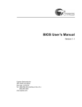
To transfer a TD list between HCD (our layer) and the Cypress BIOS:
BIOS Process:
• EZ-Host (our controller) reset: Sets SIE (serial interface engine) to
host mode, initializes the registers, sets the interrupt vectors and enables
host interrupts.
• EZ-Host device checks HUSB_SIEx_CurrentTDPtr (register): If
HUSB_SIEx_pCurrentTDPtr is not zero, there is a TD list waiting for
transfer. If [HUSB_SIEx_pCurrentTDPtr]=0, there is no TD list waiting
for transfer. Continue checking at the beginning of every frame.
• EZ-Host device transfers this TD list to USB bus: If there is a TD list
Waiting for transfer, the EZ-Host device begins to transfer this TD list to
the USB bus.
• After completion of the TD list, the EZ-Host/EZ-OTG device sends
the HUSB_TDListDone to HCD: The EZ-Host/EZ-OTG device does this
via SIE mailbox. It informs the HCD that the TD list has been finished. It
also sets semaphore at HUSB_SIEx_pTDListDone_Sem.
HCD (host controller driver) process:
HCD Configures EOT (End Of Transfer): EOT is a configurable
duration of time prior to the end of a frame. All transactions should be
completed by the time the starting point of EOT is reached. During this
Page 14 of 27
time the HCD checks the status of the previous TD list and loads a new
TD list before the next frame.
• TD_ Load: HCD prepares the TD list and loads it into the EZ-Host/EZOTG buffer. There are ping-pong buffers in the EZ-Host/EZ-OTG part to
speed up the transfer. After loading the TD list, HCD writes the TD list
pointer to HUSB_SIEx_pCurrentTDPtr.
• TD_Check: After receiving the HUSB_TDListDone, the HCD checks
the finished TD (Residue, RetryCnt, Status, and Control Bytes). The HCD
handles any transfer errors during this step.
• TD_DataCopy: HCD copies the IN data from EZ-Host/EZ-OTG. This is
done while the EZHost/EZ-OTG part transfers the TD list for the next
frame. This is possible because of the ping-pong buffers.
Page 15 of 27
Diagram of Sample TD list transfer
Page 16 of 27
Control Transfers
The one type of transfer that we were able to master for our project was a
control transfer. Control transfers are just one out of four possible types; there are
also interrupt, bulk, and isochronous transfers. Like every transfer done over
Cypress, its data must be embedded inside a TD list. Every USB device must be
able to communicate via control transfers until its initial enumeration and setup is
complete.
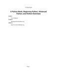
There are two possible control transfer structures: Setup-Data-Status or
Setup-Status. That is, its TD list can be either 2 or 3 nodes long. In the Setup
TD’s attached data block, the following data must be sent:
According to the values sent in these fields, the device will respond by filling in the data
block attached to the data node. If the transfer does not require data back from the device
(such as in the case of setting the device address), it will simply signal success in the
Status phase’s response bytes. The entire process is outlined in the figure below:
Page 17 of 27
Setup Phase
Data Phase
(optional)
Status Phase
TD
TD
TD
Setup Phase Data
(written by HCD)
Data Phase Data
(written by device)
(No status
phase data)
Each TD is written by the HCD and modified by the BIOS to show either success or
failure. If it was a success and data was attached, the HCD can then read the data and
send the next TD list. If there was a failure for any reason, the transfer is retried 3 times,
and then the device goes into an error state.
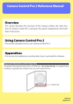
The main use for control transfers is to enumerate the USB device. This includes
providing power to the device, setting the device’s address to use from then on, reading
what type of device it is, and then choosing the desired configuration. Each step is done
with a separate TD list control transfer. Enumeration is described by the FSM below:
Page 18 of 27
However, making sense of the returned data from the device and knowing what
configuration to choose to get into the proper Configured state can be a challenge. Even
after a proper configuration is chosen, correctly using the endpoints and structuring the
subsequent TD lists is very difficult.
There was barely enough documentation to get the control transfer process working.
Since this is the most structured and standardized form of transfer, it was relatively easy
to piece together the missing parts of the picture from different sources to achieve
success. In bulk, interrupt, and isochronous transfers, however, each device has its own
unique way of communicating. Sometimes, if a device is part of a common device class,
such as Human Interface Device (HID), or Wireless, the USB Implementer’s Forum
(USB-IF) will put together a standardized way of communicating so that a new driver is
not required for each device. Some HIDs or wireless devices will not follow the
specification and therefore require a custom driver. The details of such drivers are not
easy to obtain and implement. For something as simple as a Dell USB low-speed
keyboard, however, we thought that we could succeed. However, we were unable to find
just how to structure Cypress’s proprietary TD list format to properly receive the
keyboard’s interrupt transfers. It was simple from the USB side of things, but there was
absolutely no information on the Cypress side of things. We were reduced to a trial-anderror, shooting in the dark style of development. We needed more information from
Cypress; an example would have been particularly helpful. As far as we know, nobody
yet has succeeded along this path, including those in the Xilinx forums.
Page 19 of 27
Initial USB Implementation Plan
Page 20 of 27
Final Control Implementation Diagram
Page 21 of 27
What We Learned
Time Management:
We learned many useful techniques for time management. One of them, which is
very useful, is the Gantt chart. My group at first was very skeptical of the
usefulness of the Gantt chart but we soon realized that this was a great way to
make sure we stay on schedule and keep tasks organized. We learned that we
should always keep the customer (a.k.a. professor) updated and propose a
reasonable schedule based on careful analysis of the situation.
Software Life Cycle:
We learned much more about the life cycle of a full project. This compares much
differently to any of our experiences in previous classes. Since there is no
guidelines on how to run the project, it is up to us to decide how to run the
operation. We had to come up with the idea, implement it, and maintain it in order
to finish on time. We learned many useful things in this area that could help us in
future work projects in the industry.
Debugging:
We learned a few things about debugging for an FPGA. Most of our debugging
came in the form of getting the tools to do what we wanted them to do. We
learned the ins and outs of the different connections between the hardware and
how they could mess up. Debugging this wasn’t the normal “find the bug in gdb
and fix” but a more application frustrating problem. We realized that the best way
was to systematically go through the different steps, read all the warnings, and
then proceed after each step was bug proof.
Bugs come in all shapes and sizes. The bugs we encountered ranged from stupid
mistakes to nefariously difficult errors that took hours to debug. Examples:
Stupid bugs include using the wrong kind of serial cable. We initially
wondered why we weren’t getting any output over the serial cable.
Debugging our C code was at times frustrating. Obviously, the FPGA
never returns “segmentation fault,” so when we segfaulted, we simply got
back garbage. A segfault early on the program may not manifest itself
until a lot later. C’s “undefined behavior” made our seemingly correct
code break weeks after we thought we had finished debugging.
One interesting bug was when we ran out of stack space. No errors were
given but suddenly, a lot of variables on the stack were being overwritten.
It took hours to debug; we finally realized that the bug occurs if and only
if we call a function that literally does nothing (we commented everything
out so that it just returns), which suggested that the stack was being blown.
The fix (increase the stack space) took only five seconds to implement.
(Stack size can be easily set and changed in the Xilinx Platform Studio.)
Page 22 of 27
Teamwork:
This was the first full scale group project that any of us had participated in our
time at CMU. At first, we had trouble coordinating and working as a team to
progress forward. We all had different personalities, sleep schedules, lives, and
work habits. However, with the leadership of some members in the group, we
were able to coalesce very quickly and efficiently. We were able to come to a
middle ground. The one thing we took away was that honesty and trust within
group members was the most important. If there were any problems, we voiced
them to each other so that it would be addressed sooner rather than blow up later.
Presentation Abilities:
We were able to practice our presentation skills in the class in front of a very
technical audience. We had to know what we were talking about and the one thing
we learned is that you can’t B.S. your way technically in a room full of very smart
people.
What we wish we knew before:
In hindsight, we wished we knew that in coming up with an idea, a lot of research
must be done in order to know whether it is feasible or not. The idea may sound
feasible at first, but further research must be done in order to confirm this. In our
case, we didn’t realize that there was no non-buggy documentation for the USB
port for Xilinx. If we had realized this when the idea was made, we could have
scratched it and pursued something feasible.
Page 23 of 27
Individual Pages
Ravi Raghavan
I had a great time doing this presentation with my fellow classmates. I really
enjoyed the hands on experience working with the FPGA boards. I learned that there is
more to hardware than just simulation for Verilog. Synthesizing on an actual board is
much different and can be more frustrating at times.
I personally helped out on the making of the game and a lot of the non-USB work.
Once the game was finished, I joined the help out in the USB work. In the end, everyone
in the group was helping out in the USB department, since it was the main crux of our
project. We worked on average more than 15 hours per week. Much of the work came in
the form of researching what different avenues of USB were out there and struggling with
the Xilinx Platform to do what we wanted it to do.
Even though in the end, we didn’t get the Wiimote to work through the USB, I
and the rest of the team members worked our tails off the whole semester trying till the
very last day to make it happen. I still found that this class was very rewarding in
character building. I think that the next time around, with the experience we gained, my
team members would be able to successfully complete this project.
As for improvements for the class, I would really like to see more useful demos,
especially in the areas that certain groups are working in. For example, there could be a
choice between 15-20 demos we could do. We could then pick maybe like 5 that apply to
our specific project, making it so that we develop the useful skills to complete our
project. This would definitely help the high project failure rate of the class so that people
can achieve their initial goal.
In the end, I am very happy with me and my group members. We all put in a lot
of selfless effort to get the project to the point it was at. It was apparent that we knew
what we were doing judging by the extensive knowledge of USB that is now in all our
heads. I would be glad to work with my partners again in any other class or in the
industry.
Page 24 of 27
Dennis Ting
I enjoyed implementing Duck Hunt on the FPGA board. In general, the games
aspect of the course was very entertaining. I would say my favorite part of this course
was seeing Duck Hunt work. Once we got all the input/output systems working (which
was the majority of the work), writing the actual Duck Hunt code was a relaxing and
fruitful exercise. If we had more time and finished all our tasks, I would’ve wanted to
implement more games using the codebase we already have.
In general, our group worked on most of the tasks together. We first tackled the
labs, and then began work on the actual Duck Hunt itself. The one task that was both
enjoyable and simultaneously frustrating is debugging the software that we’ve written,
especially debugging the frame buffer code. Finally killing the bugs is by far the best
part of software coding, but at the same time, it was frustrating that despite my best
efforts, I was unable to write code that was even remotely bug-free.
I also liked the freedom we were given in implementing Duck Hunt. We were
allowed to choose how to go about tackling the problem. Our hacked code was difficult
to debug, and I learned that it’s a good idea to write and refactor code.
Although I enjoyed the software side, I did not really enjoy working with Xilinx’s
Platform Studio. To give an example, Xilinx’s software cannot handle spaces in the
command path. If we attempt to load a file with a space in its path, XPS (Xilinx Platform
Studio) simply fails to open. No error messages are given.
In terms of time spent, although this course is a 12 unit course, we averaged over
15 hours per week. I would recommend not taking any heavy courses alongside the ECE
capstone courses. Also, the job search and on-site interviews made my schedule pretty
hectic. I don’t regret my schedule, but this semester was definitely more work than I
originally anticipated.
We did ultimately get Wiimote working through the computer, using third-party
programs that interact with Bluetooth to talk with the Wiimote. However, even then, we
realized that these programs were buggy. Bluetooth, at times, simply just failed.
Considering that even on the computer, Wiimote interactions are somewhat buggy, in
hindsight, trying to get Wiimote working from scratch on the FPGA was perhaps way too
optimistic.
Page 25 of 27
Anthony Setto
I liked how open-ended this class was. Any group could do just about anything
they wanted in any way they wanted, for better or for worse. This gave me valuable
experience for what it would be like to work in the industry as a team leader or a member
of a small team. Time management was a huge worry the entire semester; this was
something we did not have to deal with much in the past.
At the beginning of the semester, all three of us worked together on everything,
including the labs and the beginning of the duck hunt game, as a learning exercise. After
the first few weeks, we began to branch out into different tasks. My task, unfortunately,
was to get USB to work. My frustration with Xilinx and Cypress is far beyond the scope
of this review, but I’ll just say that the university should strongly consider switching
FPGA providers. I estimate that I spent 20 hours a week in the lab, figuratively banging
my head off of hard surfaces.
However, I was proud of the successes that we were able to accomplish, including
the communication between some USB devices. I also liked that we were able to quickly
fall back to the serial connection for the final demo. Writing the duck hunt game from
scratch was pretty impressive, especially since it’s better than the original in my opinion.
I also liked working with my team, as my lab partners were honest, talented, and fun to
work with.
I would like to see more labs and useful demos for the class, especially for the
Virtex V and for the newest version of XPS. We wasted countless hours at the beginning
wrestling with Xilinx incompatibility errors and other confusing roadblocks.
Page 26 of 27
Citations
www.usb.org – The place to go to get a great overview on how USB works in general.
Also contains the USB Implementer’s Forum, which is a necessity to get any USB
project to work.
www.bluetooth.com – Contains the spec for the Bluetooth protocol and outlines
processes used by Bluetooth devices, like the Wiimote.
http://carl.kenner.googlepages.com/glovepie_download - The download location for
GlovePIE, a powerful PC input manipulation program used to interpret the input from the
Wiimote.
http://java.sun.com/products/javacomm/ - Location of Java’s .comm library, which was
used to send serial information to the board.
www.cypress.com – Cypress’s homepage, contains information on the external USB
controller
http://www.xilinx.com/univ/xupv5-lx110t-bsb.htm - Xilinx designs we used as a place to
start for our designs
http://tsgk.captainn.net/index.php?p=showsheets&t=sr&sr=151 – Sprites for the Duck
Hunt game
http://www.computer-engineering.org/ps2mouse/ - An excellent source that documents
the PS/2 mouse interface. Because PS/2 mouses have been replaced by USB mouses, this
is one of the few PS/2 references left.
Page 27 of 27