1
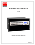
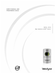
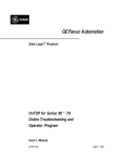
Multicon SNMP Data Model
Multicon
SNMP Data Model
User manual
Rev. 0
Nevion Europe AS
P.O. Box 1020, 3204 Sandefjord, Norway – Tel: +47 33 48 99 99 – Fax: +47 33 48 99 98
www.nevion.com
Multicon SNMP Data Model
Rev. 0
Nevion Support
Nevion Europe
Nevion USA
P.O. Box 1020
3204 Sandefjord, Norway
Support phone 1: +47 33 48 99 97
Support phone 2: +47 90 60 99 99
1600 Emerson Avenue
Oxnard, CA 93033, USA
Toll free North America: (866) 515-0811
Outside North America: +1 (805) 247-8560
E-mail: [email protected]
See http://www.nevion.com/support/ for service hours for customer support globally.
Revision history
Current revision of this document is the uppermost in the table below.
Rev.
Repl.
Date
Sign
0
-
20090702
JIH
Change description
First official release
nevion.com | 2
Multicon SNMP Data Model
Rev. 0
Contents
Revision history........................................................................................................ 2
1 Product overview .................................................................................................. 4
2 Data model .......................................................................................................... 5
2.1 High-level overview ......................................................................................................... 5
2.2 Current MIB structure – nworktwo .................................................................................. 6
2.3 Block functions – module ................................................................................................ 7
2.4 Block addressing – module .............................................................................................. 7
2.5 VikinX router control – level............................................................................................. 8
2.6 Flashlink router matrix control – level .............................................................................. 8
2.7 Generic tree - generic ...................................................................................................... 8
3 Notifications ......................................................................................................... 9
4 Data model overview .......................................................................................... 10
General environmental requirements for Nevion equipment .................................. 12
Product Warranty .................................................................................................. 13
nevion.com | 3
Multicon SNMP Data Model
Rev. 0
1 Product overview
Multicon is the next-generation element manager for Flashlink system and system controller
for VikinX range of routers. The product is based on a new open and distributed architecture
and enables customers to deploy one control system for both Flashlink and VikinX.
The new product offers a range of important improvements for router control and also
supports control panel access to Flashlink parameters, which is increasingly important for
signal processing and distribution applications.
For a more detailed overview of the Multicon product refer to the main manual. This
document describes the SNMP interface provided by Multicon for monitoring and
configuration of Flashlink systems and VikinX routers.
nevion.com | 4
Multicon SNMP Data Model
Rev. 0
2 Data model
2.1 High-level overview
The figure below gives an overview of the hierarchy of the MIB model implemented for
Flashlink and VikinX.
Deprecated
Figure 1: High-level MIB structure
The
MIB
structure
is
located
under
the
enterprise
OID
iso.org.dod.internet.private.enterprises.nwork.products (1.3.6.1.4.1.8768.1). The structure
beneath products (1) is described below:
•
flashlink (1): deprecated and should not be used, only included for backwards
compatibility with older Flashlink cards
•
vikinx (2): deprecated and should not be used, only included for backwards
compatibility
•
conquer (3): deprecated and should not be used, only included for backwards
compatibility with older Flashlink SP&D cards
•
nworktwo (4): currently supported MIB structure for both Flashlink systems and
VikinX routers
Note that it is not necessary to use the flashlink (1), vikinx (2) and conquer (3) MIB structures
for new implementations as older Flashlink equipment and VikinX routers is also supported
by the currently supported MIB structure under nworktwo (4).
nevion.com | 5
Multicon SNMP Data Model
Rev. 0
2.2 Current MIB structure – nworktwo
The figure below gives an overview of the nworktwo (4) MIB structure that is currently
supported for Flashlink systems and VikinX routers.
Figure 2: nworktwo (4) MIB structure
The currently supported MIB structure for Flashlink systems and VikinX routers is located
under the enterprise OID iso.org.dod.internet.private.enterprises.nwork.products.nworktwo
(1.3.6.1.4.1.8768.1.4). The structure beneath nworktwo (4) is described below:
nevion.com | 6
Multicon SNMP Data Model
Rev. 0
•
bus (1): includes busSysType and busNum parameters that is used as index for tables
under netInterface (2), router (3), gydaBus (4) and module (5)
•
netInterface (2): not in use
•
router (3): includes table with general information about managed routers
•
gydaBus (4): for internal use only
•
module (5): this is the most important part of the MIB structure for Flashlink systems,
which includes tables corresponding to logical functions of each module. Note that a
module here is either a Flashlink card or a VikinX router.
•
partition (6): deprecated and should not be used, includes partition info for VikinX
routers.
•
level (7): this part of the MIB structure is used for controlling levels and cross-point
settings for VikinX routers, but also for controlling matrixes in Flashlink.
•
event (8): not in use
2.3 Block functions – module
Each table in the MIB corresponds to a logical function on the card it belongs to. Any card
may have any number of each type of block, depending on the type of card.
Each table contains a superset of attributes for each function block, thus there is likely to be
unimplemented attributes for most blocks. In a future version of Gyda/Multicon, attributes
will be filtered so that only relevant attributes are presented.
For reference to the description for each table within the module tree please refer to the
description within the MIB file itself.
Example:
cableEQTable OBJECT-TYPE
SYNTAX SEQUENCE OF CableEQEntry
ACCESS not-accessible
STATUS mandatory
DESCRIPTION
"The cableEQTable lists all cableEQs for those modules that have them. A module can
have zero or more cableEQs."
::= { module 5 }
This tells you that this is a table containing all cable equalizers in the system.
2.4 Block addressing – module
Any number of function block of any time may reside on any single card, so the data model
is designed for flexibility. Every block is addressed with a 4-dimensional index, although in
practice only two of these dimensions are in use for any controller. The busSysType
parameter is always 2 (gyda) for Flashlink cards, and busNum is usually 1 for Flashlink cards.
This may have been changed in configuration of the Gyda controller.
The last two indices are in active use. moduleNum matches the card position, counting index0, i.e. card position 5 in rack 0 corresponds to moduleNum = 4, position 8 in rack 4
corresponds to moduleNum = 47. The last index is uniquely named for all blocks, but is
simple the address of an instance of that particular table.
nevion.com | 7
Multicon SNMP Data Model
Rev. 0
Example 1:
NWORK-MIB::moduleAlarmCount.gyda.1.4 = INTEGER: 1
NWORK-MIB::moduleAlarmCount.gyda.1.6 = INTEGER: 5
This shows the module alarm count for Flashlink cards with moduleNum 4 and 6, which
translates to cards in frame 0 slots 5 and 7.
Example 2:
NWORK-MIB::cableEQAlarmStatus.gyda.1.6.0 = INTEGER: notacked(3)
NWORK-MIB::cableEQAlarmStatus.gyda.1.6.1 = INTEGER: notacked(3)
This shows the card equalizer alarm status for Flashlink card with moduleNum 6 (frame 0 slot
7). In this case the card has two cable equalizers, which are presented with an additional
index to specify the cable equalizers, in this case 0 and 1.
2.5 VikinX router control – level
All globally mapped router levels, i.e. levels that are enabled through the System
Configurator for Multicon, are controllable through entries in crosspointTable. levelTable gives
a summary of the router level, and should be used to discover which levels are available in
the system.
Example:
NWORK-MIB::crosspointInputNum.3.0 = INTEGER: 0
NWORK-MIB::crosspointInputNum.3.1 = INTEGER: 26
NWORK-MIB::crosspointInputNum.3.2 = INTEGER: 5
...
This shows for level 3 which input in this level the cross-point is switched to, in this case
input 0 is switched to output 0, 1 to 26 and 2 to 5.
2.6 Flashlink router matrix control – level
For historical reasons, router control is left outside the module addressed data tree. The card
address can still be derived from the level number, as the level numbers for matrices residing
in Flashlink cards are calculated from the following formula:
Level = 10000 + positioncard x 10 + subindexmatrix
These levels are presented in addition to the levels mapped using the System Configurator,
and are only available on the controller with the physical connection to the cards.
Example:
NWORK-MIB::crosspointInputNum.10080.0 = INTEGER: 0
NWORK-MIB::crosspointInputNum.10080.1 = INTEGER: 0
NWORK-MIB::crosspointInputNum.10080.2 = INTEGER: 4
...
This shows level 10080 which represents the Flashlink card in position 8 with matrix index 0.
In this case it is an AV-HD-XMUX de-embedder matrix.
2.7 Generic tree - generic
The MIB also contains a generic tree on the same level as products
iso.org.dod.internet.private.enterprises.nwork.generic (1.3.6.1.4.1.8768.4). This part of the
MIB may be used for retrieving log information from Multicon.
nevion.com | 8
Multicon SNMP Data Model
Rev. 0
3 Notifications
Multicon has the capability to send SNMP notifications (traps) when alarms occur in a
Flashlink system or VikinX router. The trap types supported are listed in the MIB file.
There are one trap type indicating the raise of an alarm and a corresponding trap type to
indicate clear of an alarm. Each trap type contains values from the SNMP data model
pertaining to the alarm situation, which enables SNMP managers to poll for more
information when a trap is received.
Example:
nworkLossOfOptSignal TRAP-TYPE
ENTERPRISE generic
VARIABLES { busSysType, busNum, moduleNum, moduleLabel, optInputNum }
DESCRIPTION "Loss of input signal on optical input."
::= 3
nworkCorrectOptSignal TRAP-TYPE
ENTERPRISE generic
VARIABLES { busSysType, busNum, moduleNum, moduleLabel, optInputNum }
DESCRIPTION "Signal on optical input comes back after having been lost."
::= 4
The example above shows an loss of optical signal alarm and a corresponding clear alarm. In
each case the values of busSysType, busNum, moduleNum, moduleLabel and optInputNum
is sent with the trap.
nevion.com | 9
Multicon SNMP Data Model
Rev. 0
4 Data model overview
The figure on the next page gives a total overview of the entire SNMP data model for
Multicon.
For reference to the description and possible values for each parameter please refer to the
description within the MIB file itself.
Example:
moduleStatus OBJECT-TYPE
SYNTAX INTEGER { ok(1), fail(2), removed(3) }
ACCESS read-only
STATUS mandatory
DESCRIPTION
"Is the module present and operating?"
::= { moduleEntry 3 }
This shows that it is a read-only parameter with the possible values ok, fail and removed. A
relevant description is also shown above.
Note that it is highly recommended to use a MIB browser to read the MIB file as it can be
very hard to read the MIB as a text file.
nevion.com | 10
Multicon SNMP Data Model
Rev. 0
voltageEntry
videoScalerEntry
PK,FK1
PK,FK1
PK,FK1
PK
optAmpEntry
videoScalerStatus
videoScalerLinesIn
videoScalerFrameRateIn
videoScalerFrameStructureIn
videoScalerAspectRatioIn
videoScalerAspectRatioInMode
videoScalerPan
videoScalerTilt
videoScalerLinesOut
videoScalerFrameRateOut
videoScalerFrameStructureOut
videoScalerAspectRatioOut
videoScalerAncPasthru
videoScalerAlarmStatus
videoScalerAlarmTrap
PK,FK1
PK,FK1
PK,FK1
PK
busSysType
busNum
moduleNum
optAmpNum
optAmpSignalMode
optAmpGainMode
optAmptControlMode
optAmpGain
optAmpoutput
PK,FK1
PK,FK1
PK,FK1
PK
busSysType
busNum
moduleNum
videoGenNum
videoGenWss
videoGenLines
videoGenFrameRate
videoGenFrameStructure
videoGenPattern
videoGenY
videoGenCb
videoGenCr
busSysType
busNum
busName
PK,FK1
PK,FK1
PK,FK1
PK
busSysType
busNum
moduleNum
audioProcEntry
PK,FK1
PK,FK1
PK,FK1
PK
choBlockEntry
PK,FK1
PK,FK1
PK,FK1
PK
busSysType
busNum
moduleNum
choBlockNum
vadcEntry
audioGenEntry
busSysType
busNum
moduleNum
colourSpaceNum
busSysType
busNum
moduleNum
audioGenNum
colourSpaceEnable
colourSpaceInputMode
colourSpaceInput
colourSpaceOutput
audioGenSampleRate
audioGenWordLength
audioGenChannels
audioGenLevel
audioGenPattern
audioGenFrequency
serialPortEntry
PK,FK1
PK,FK1
PK,FK1
PK
levelEntry
busSysType
busNum
moduleNum
serialPortNum
serialPortEnable
serialPortStatus
serialPortDatabits
serialPortParity
serialPortSpeed
serialPortAlarmStatus
serialPortAlarmTrap
levelNum
levelInputs
levelOutputs
levelName
levelTypeVideo
levelTypeVideoAnalogue
levelTypeVideoSDI
levelTypeVideoHDSDI
levelTypeAudio
levelTypeAudioAnalogue
levelTypeAudioAES
levelTypeData
levelTypeDataVideo
levelTypeDataAudio
levelTypeTieline
levelTypeTielineVideo
levelTypeTielineAudio
busSysType
busNum
moduleNum
gpioNum
levelNum
crosspointOutputNum
crosspointInputNum
crosspointLocking
crosspointLockUID
busSysType
busNum
moduleNum
embedderNum
embedderType
embedderGroup
embedderStripGroup
embedderWordLength
embedderStatus
embedderAlarmStatus
embedderAlarmTrap
monitorEntry
PK,FK1
PK,FK1
PK,FK1
PK
PK,FK1
PK,FK1
PK,FK1
PK
busSysType
busNum
moduleNum
vdacNum
busSysType
busNum
moduleNum
optInputNum
cableEQConfig
cableEQStatus
cableEQAlarmStatus
cableEQAlarmTrap
syncSourceEntry
PK,FK1
PK,FK1
PK,FK1
PK
vdacFormat
vdacMod50
vdacWss
vdacWssMode
vdacMod60
vdacSetup
vdacLines
vdacFrameRate
vdacFrameStructure
vdacAlarmStatus
vdacAlarmTrap
vdacSubCarrierPhase
busSysType
busNum
moduleNum
syncSourceNum
syncSourceType
syncSourceLines
syncSourceFrameRate
syncSourceFrameStructure
syncSourceSampleRate
syncSourceWordLength
syncSourceAlarmStatus
syncSourceAlarmtrap
audioBlockEntry
laserEntry
cableDriverEntry
PK,FK1
PK,FK1
PK,FK1
PK
busSysType
busNum
moduleNum
cableDriverNum
cableDriverConfig
cableDriverSlewRate
PK,FK1
PK,FK1
PK,FK1
PK
busSysType
busNum
moduleNum
laserNum
laserWavelength
laserPower
laserConfig
laserStatus
laserAlarmStatus
laserAlarmTrap
PK,FK1
PK,FK1
PK,FK1
PK
busSysType
busNum
moduleNum
monitorNum
monitorType
monitorSignaltype
monitorSignalFormat
monitorAlarmStatus
monitorAlarmTrap
monitorErrorCountMax
monitorErrorCount
monitorErrorDeltaAlarm
monitorErrorCountAlarm
monitorErrorFreeAlarm
monitorErrorFreeCount
monitorMaskVS
monitorMaskFFCRC
monitorMaskAPCRC
monitorMaskLock
monitorMaskANCS
monitorMaskLCRC
monitorMaskLNUM
monitorMaskTRS
monitorMaskFFEDA
monitorMaskFFIDH
monitorMaskFFIDA
monitorMaskFFUES
monitorMaskAPEDA
monitorMaskAPIDH
monitorMaskAPIDA
monitorMaskAPUES
monitorMaskANEDH
monitorMaskANEDA
monitorMaskANIDH
monitorMaskANIDA
monitorMaskANUES
optInputStatus
optInputRSSI
optInputAlarmStatus
optInputAlarmTrap
busSysType
busNum
moduleNum
cableEQNum
rfAmpEntry
crosspointEntry
PK,FK1
PK
PK,FK1
PK,FK1
PK,FK1
PK
busSysType
busNum
moduleNum
temperatureNum
PK,FK1
PK,FK1
PK,FK1
PK
cableEQEntry
PK,FK1
PK,FK1
PK,FK1
PK
busSysType
busNum
moduleNum
vadcNum
vadcFormat
vadcWss
vadcSetup
vadcLines
vadcFrameRate
vadcFrameStructure
vadcMark
vadcAgc
vadcFilter
vadcGainR
vadcGainG
vadcgainB
vadcLumaBrightness
vadcLumaContrast
vadcChromaSaturation
vadcChromaHue
vadcYBrightness
vadcYContrast
vadcPbSaturation
vadcPrSaturation
vadcAlarmStatus
vadcAlarmTrap
embedderEntry
fanNominal
fanSpeed
fanUpperLimit
fanLowerLimit
fanAlarmStatus
fanAlarmTrap
temperatureDescription
temperatureNominal
temperatureValue
temperatureUpperLimit
temperatureLowerLimit
temperatureAlarmStatus
temperatureAlarmTrap
reclockerConfig
reclockerConfigASI
reclockerLoopBW
reclockerStatus
reclockerBitRate
reclockerAlarmStatus
reclockerAlarmTrap
vdacEntry
colourSpaceEntry
busSysType
busNum
moduleNum
fanNum
optInputEntry
PK,FK1
PK,FK1
PK,FK1
PK
PK,FK1
PK,FK1
PK,FK1
PK
PK,FK1
PK,FK1
PK,FK1
PK
busSysType
busNum
moduleNum
reclockerNum
gpioMode
gpioStatus
gpioDescription
gpioAlarmStatus
gpioAlarmTrap
audioProcMode
audioProcInputs
audioProcOutputs
choBlockSize
choBlockMode
choBlockRule
choBlockLatch
choBlockHoldTime
choBlockLockTime
choBlockPri1
choBlockPri2
choBlockPri3
choBlockAlarmStatus
choBlockAlarmtrap
PK,FK1
PK,FK1
PK,FK1
PK
PK,FK1
PK,FK1
PK,FK1
PK
busSysType
busNum
moduleNum
audioProcNum
PK,FK1
PK,FK1
PK,FK1
PK
temperatureEntry
reclockerEntry
gpioEntry
PK,FK1
PK,FK1
PK,FK1
PK
fanEntry
busSysType
busNum
moduleNum
voltageNum
voltageNominal
voltageValue
voltageUpperLimit
voltageLowerLimit
voltageAlarmStatus
voltageAlarmTrap
delayType
delayStatus
delayDescription
delayFrames
delayLpF
delayLines
delaySpL
delaySamples
delaySampleRate
delaySeconds
delayNanosecs
moduleEntry
PK,FK1
PK,FK1
PK
PK,FK1
PK,FK1
PK,FK1
PK
busSysType
busNum
moduleNum
delayNum
busSysType
busNum
moduleNum
ethPortNum
ethPortEnable
ethPortSignal
ethPortDuplexMode
ethPortMdiMode
ethPortMsMode
ethPortSpeed
ethPortAlarmStatus
ethPortAlarmTrap
PK
PK
PK
moduleType
moduleStatus
moduleLabel
moduleAlarmStatus
moduleAlarmTrap
moduleAlarmCount
ethPortEntry
PK,FK1
PK,FK1
PK,FK1
PK
delayEntry
busEntry
videoGenEntry
busSysType
busNum
moduleNum
videoScalerNum
PK,FK1
PK,FK1
PK,FK1
PK
busSysType
busNum
moduleNum
audioBlockNum
audioBlockChannelCount
audioBlockIncominFormat
audioBlockIncomingSampleRate
audioBlockIncomingWordLength
audioBlockSRC
audioBlockOutgoingFormat
audioBlockOutgoingSampleRate
audioBlockOutgoingWordLength
audioBlockStatus
audioBlockAlarmStatus
audioBlockAlarmTrap
busSysType
busNum
moduleNum
rfAmpNum
rfAmpmode
rfAmpGain
nevion.com | 11
General environmental requirements for Nevion equipment
1.
The equipment will meet the guaranteed performance specification under the
following environmental conditions:
-
Operating room temperature range:
Operating relative humidity range:
2.
The equipment will operate without damage under the following environmental
conditions:
-
Temperature range:
Relative humidity range:
0°C to 45°C
<90% (non-condensing)
-10°C to 55°C
<95% (non-condensing)
Multicon SNMP Data Model
Rev. 0
Product Warranty
The warranty terms and conditions for the product(s) covered by this manual follow the
General Sales Conditions by Nevion, which are available on the company web site:
www.nevion.com
nevion.com | 13