1
GE Fanuc Automation
Programmable Control Products
PACSystems® RX3i
Serial Communications Modules
User’s Manual, GFK-2460A
March 2007
GFL-002
Warnings, Cautions, and Notes
as Used in this Publication
Warning
Warning notices are used in this publication to emphasize that hazardous voltages,
currents, temperatures, or other conditions that could cause personal injury exist in this
equipment or may be associated with its use.
In situations where inattention could cause either personal injury or damage to equipment,
a Warning notice is used.
Caution
Caution notices are used where equipment might be damaged if care is not taken.
Note
Notes merely call attention to information that is especially significant to understanding and
operating the equipment.
This document is based on information available at the time of its publication. While efforts
have been made to be accurate, the information contained herein does not purport to cover all
details or variations in hardware or software, nor to provide for every possible contingency in
connection with installation, operation, or maintenance. Features may be described herein
which are not present in all hardware and software systems. GE Fanuc Automation assumes no
obligation of notice to holders of this document with respect to changes subsequently made.
GE Fanuc Automation makes no representation or warranty, expressed, implied, or statutory
with respect to, and assumes no responsibility for the accuracy, completeness, sufficiency, or
usefulness of the information contained herein. No warranties of merchantability or fitness for
purpose shall apply.
The following are trademarks of GE Fanuc Automation, Inc.
Alarm Master
Genius
ProLoop
Series Six
CIMPLICITY
Helpmate
PROMACRO
Series Three
CIMPLICITY 90–ADS
Logicmaster
PowerMotion
VersaMax
CIMSTAR
Modelmaster
PowerTRAC
VersaPoint
Field Control
Motion Mate
Series 90
VersaPro
GEnet
PACSystems
Proficy
Series Five
Series One
VuMaster
Workmaster
©Copyright 2007 GE Fanuc Automation North America, Inc.
All Rights Reserved
Contents
Chapter 1
Introduction............................................................................................ 1-1
Introduction to PACSystems RX3i Serial Communications Modules ............................... 1-2
Module Specifications............................................................................................... 1-3
Communications Standards ..................................................................................... 1-4
Introduction to Installing Serial Communications Modules ............................................... 1-5
MODBUS Multidrop RS-485..................................................................................... 1-5
Introduction to Serial Communications Module Configuration.......................................... 1-6
Introduction to Serial Communications Module Data........................................................ 1-7
Status and Control Data ........................................................................................... 1-7
Serial Communications Data.................................................................................... 1-7
Introduction to MODBUS Communications....................................................................... 1-8
Supported MODBUS Functions ............................................................................... 1-8
Supported Transmission Mode ................................................................................ 1-8
Introduction to Serial I/O Communications ....................................................................... 1-9
Monitoring and Controlling Serial I/O Communications ........................................... 1-9
Introduction to CCM Slave Communications .................................................................. 1-10
Chapter 2
Installation and Wiring .......................................................................... 2-1
Installation in Hazardous Locations .................................................................................. 2-2
LEDs.................................................................................................................................. 2-3
Serial Ports........................................................................................................................ 2-4
Port Pin Assignments ............................................................................................... 2-4
Termination ....................................................................................................................... 2-5
Point to Point Serial Connections ..................................................................................... 2-6
RS-232 MODBUS..................................................................................................... 2-6
MODBUS Multidrop Connections...................................................................................... 2-7
Grounding and Ground Loops.................................................................................. 2-8
Multidrop Connections for Four-Wire MODBUS ...................................................... 2-9
Multidrop Connections for Two-Wire MODBUS ..................................................... 2-11
Chapter 3
Configuration ......................................................................................... 3-1
Configuring Basic Module Settings ................................................................................... 3-2
I/O Settings ............................................................................................................... 3-2
General Settings....................................................................................................... 3-2
Configuring a Port for Serial I/O Protocol.......................................................................... 3-3
Serial Port Settings................................................................................................... 3-3
Serial I/O Port Data .................................................................................................. 3-4
Configuring a Port for MODBUS Master Protocol............................................................. 3-8
Serial Port Settings................................................................................................... 3-8
Configuring MODBUS Master Exchanges ............................................................. 3-10
Configuring a Port for MODBUS Slave Protocol............................................................. 3-13
Serial Port Settings................................................................................................. 3-13
GFK-2460A
iii
Contents
Automatic MODBUS Slave Exchanges.................................................................. 3-15
Customizing MODBUS Slave Exchanges .............................................................. 3-15
Setting Up MODBUS Slave Data Exchanges ........................................................ 3-16
Configuring a Port for CCM Slave Protocol .................................................................... 3-18
Serial Port Settings................................................................................................. 3-18
Setting Up CCM Slave Data Exchanges ................................................................ 3-20
Chapter 4
Port Status and Control Data................................................................ 4-1
Transfer of Status and Control Data ................................................................................. 4-2
Port Status Input Data....................................................................................................... 4-3
Input Data Definitions ............................................................................................... 4-5
Port Control Output Data................................................................................................... 4-9
Output Data Definitions .......................................................................................... 4-10
Error Status Handling...................................................................................................... 4-14
Using DO I/O and Suspend I/O....................................................................................... 4-15
DO I/O Function Block Format ............................................................................... 4-15
Chapter 5
MODBUS Communications................................................................... 5-1
MODBUS Communications Overview .............................................................................. 5-2
Unicast or Broadcast Messages............................................................................... 5-2
Messages and Responses ....................................................................................... 5-2
MODBUS Message Formats .................................................................................... 5-4
MODBUS Data Addressing ...................................................................................... 5-5
MODBUS Communications for RX3i Serial Communications Modules ........................... 5-6
Supported MODBUS Functions ............................................................................... 5-6
Supported Transmission Mode ................................................................................ 5-6
How MODBUS Functions are Implemented............................................................. 5-7
MODBUS Master Operation for RX3i Serial Communications Modules........................... 5-8
How the Module Handles a Write Request in Master Mode .................................... 5-9
How the Module Handles a Read Request in Master Mode .................................... 5-9
MODBUS Master Diagnostics ................................................................................ 5-10
MODBUS Slave Operation for RX3i Serial Communications Modules........................... 5-11
How the Module Handles a Read Request in Slave Mode .................................... 5-11
How the Module Handles a Write Request in Slave Mode .................................... 5-11
MODBUS Functions for RX3i Serial Communications Modules..................................... 5-12
Read Coil Status (Read Output Table), MODBUS Function 01............................. 5-12
Read Input Status (Read Input Table), MODBUS Function 02.............................. 5-13
Read Holding Registers (Read Registers), MODBUS Function 03 ....................... 5-14
Read Input Registers (Read Analog Inputs), MODBUS Function 04..................... 5-15
Force Single Coil, MODBUS Function 05 .............................................................. 5-16
Preset/Write Single Register, MODBUS Function 06 ............................................ 5-17
Read Exception Status, MODBUS Function 07 ..................................................... 5-18
Diagnostics, Return Query Data, MODBUS Function 08....................................... 5-19
Write Multiple Coils (Force Multiple Outputs), MODBUS Function 15 ................... 5-20
Preset/Write Multiple Registers, MODBUS Function 16 ........................................ 5-21
iv
PACSystems® RX3i Serial Communications Modules –March 2007
GFK-2460A
Contents
Report Slave ID, MODBUS Function 17 ................................................................ 5-22
Mask Write 4x Memory (Register Table), MODBUS Function 22 .......................... 5-23
Read/Write 4x (Register Table) Memory, MODBUS Function 23 .......................... 5-24
Chapter 6
Serial I/O Communications ................................................................... 6-1
Serial I/O Communications for RX3i Serial Communications Modules ............................ 6-2
Serial I/O Features of Serial Communications Modules .......................................... 6-2
Local Serial I/O Operations ............................................................................................... 6-3
Initializing (Resetting) the Port ................................................................................. 6-3
Managing Hardware Flow Control for RS-232 Communications ............................. 6-3
Reading Serial I/O Data .................................................................................................... 6-4
Reading the Port Status ........................................................................................... 6-4
Flushing the Input Buffer .......................................................................................... 6-4
Reading Input Data................................................................................................... 6-5
Writing Serial I/O Data ...................................................................................................... 6-6
Dialing a Modem....................................................................................................... 6-7
Chapter 7
CCM Communications........................................................................... 7-1
CCM Overview .................................................................................................................. 7-2
CCM Commands for RX3i Serial Communications Modules............................................ 7-3
CCM Memory Types................................................................................................. 7-4
CCM Slave Operations for the Serial Communications Module ....................................... 7-5
Write Request from the CCM Master ....................................................................... 7-5
Normal Read Request from the CCM Master .......................................................... 7-6
Quick Read Request from the CCM Master............................................................. 7-6
Scratchpad Data ............................................................................................................... 7-7
Diagnostics Data for CCM Slave Ports ............................................................................. 7-8
Transmission Errors ................................................................................................. 7-9
GFK-2460A
Contents
v
Contents
vi
PACSystems® RX3i Serial Communications Modules –March 2007
GFK-2460A
Chapter Introduction
1
This chapter is an introduction to the PACSystems RX3i Serial Communications modules:
▪
Introduction to PACSystems RX3i Serial Communications Modules
▪
▪
▪
▪
▪
Introduction to Serial Communications Module Configuration
Introduction to Serial Communications Module Data
Status and Control Data
Serial Communications Data
Introduction to MODBUS Communications
▪
▪
▪
▪
Communications Standards
Introduction to Installing Serial Communications Modules
▪
▪
▪
Module Specifications
Supported MODBUS Functions
Supported Transmission Mode
Introduction to Serial I/O Communications
Introduction to CCM Slave Communications
Additional Documentation
PACSystems Serial Communications Modules IC695CMM002 and IC695CMM004, GFK2461. This datasheet-type document contains the same module descriptions and
specifications found in this user manual, plus the most up-to-date release information for
these two modules.
PACSystems RX3i System Manual, GFK-2314. This manual details system and module
installation procedures, and includes descriptions and specifications of PACSystems RX3i I/O
and option modules.
PACSystems RX3i user manuals, module datasheets, and other important product
documents are available online at www.gefanuc.com. They are also included in the Infolink for
PLC documentation library on CDs, catalog number IC690CDR002.
RX3i Serial Communications modules function as part of a larger control system. Additional
documentation may be needed to complete the system installation and configuration.
GFK-2460A
1-1
1
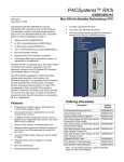
Introduction to PACSystems RX3i Serial Communications Modules
PACSystems RX3i Serial Communications modules expand the serial
communications capabilities of an RX3i system.
Serial Communications module IC695CMM002 provides two
independent, isolated serial ports. Serial Communications module
IC695CMM004, illustrated at right, provides four independent, isolated
serial ports. Up to six Serial Communications modules can be located
in the main PACSystems RX3i backplane.
MODULE OK
PORT FAULT
P1
P2:
P3:
P4:
STATUS
Each port can be configured for MODBUS Master, MODBUS Slave,
Serial I/O protocol. In addition, for modules that are version 1.02 or later, each
port can be configured for CCM Slave protocol.
PORT 1
STATUS
PORT 2
Additional module features include:
▪
▪
▪
▪
▪
▪
▪
▪
Port-to-port isolation and port-to-backplane isolation.
RS-232, RS-485/422 communication, software-selected
Hardware handshake: RTS/CTS for RS-232
Selectable Baud Rates: 1200, 2400, 4800, 9600, 19.2K, 38.4K,
57.6K, 115.2K
Module fault status reporting (Watchdog, Ram Fail, Flash Fail)
Module identity and status reporting, including LED status indicators
Meets CE, UL/CUL 508 and 1604, and ATEX requirements
Flash memory for future upgrades
STATUS
PORT 3
STATUS
PORT 4
IC695CMM004
These modules must be located in an RX3i Universal Backplane. An
RX3i CPU with firmware version 3.83 or later is required. Machine
Edition 5.5 with Service Pack 2 SIM 4 or later is required for configuration. Machine Edition
5.6 SIM 6 or later is required for CCM Slave protocol. RX3i Serial Communications Modules
can be hot-inserted and removed following the instructions in the PACSystems RX3i System
Manual, GFK-2314.
1-2
PACSystems® RX3i Serial Communications Modules – March 2007
GFK-2460A
1
Module Specifications
Number of Serial Ports
IC695CMM002: two independent serial ports
IC695CMM004: four independent serial ports
Connectors
RJ-45
Number of Serial
Communications
Modules per CPU
Six in the main CPU backplane
Backplane power
requirements
IC695CMM002
0.7 Amps maximum @ 3.3 VDC
0.115 Amps maximum @ 5.0 VDC
IC695CMM004
0.7 Amps maximum @ 3.3 VDC
0.150 Amps maximum @ 5.0 VDC
LEDs
Module OK, Port Fault, Port Status (2 or 4)
Port Type
RS-232 or RS-485/22,
4-wire (full duplex) or 2-wire (half-duplex) operation for RS-485/422
Flow Control for R-232
Selectable: Hardware (CTS/RTS) or none
Turnaround Delay
6mS minimum enforced by module. External devices must hold off
response for at least 6ms after the last character received.
Baud rates
1200, 2400, 4800, 9600, 19.2K, 38.4K, 57.6K, 115.2K
Parity
Even, odd, none
Data bits
7, 8
Stop bits
1, 2
Operating Temperature
0°C to + 60°C
Input Impedance
Zin > 96 kOhm for RS-485/422
3 kOhm < Zin < 7 kOhm for RS-232
Max Overvoltage
+/- 25V
Channel-Channel
Crosstalk
-55 dB minimum
Isolation
Port to Backplane and to frame ground: 250 VAC continuous; 1500
VAC for 1 minute, 2550VDC for one second.
Port to port: 500VDC continuous, 710VDC for one minute.
In order to meet emission and immunity requirements for the EMC directive (CE mark),
shielded cable must be used with this module.
GFK-2460A
Chapter 1 Introduction
1-3
1
Communications Standards
Each port on an RX3i Serial Communications module supports the RS-232, RS-422, and RS485 standards for asynchronous serial communications. RS-485 has largely replaced RS-422,
because it guarantees multidrop capability.
RS-232
In RS-232 mode, a port transmits and receives data and control signals on unbalanced
circuits, with one Signal Common (or Signal Ground) wire serving as the return path for all the
data and control circuits. RS-232 is suitable for point-to-point connections up to about 25
meters in length. It is not suitable for longer lines or multidrop connections. The RS-232
specification recommends limiting the data rate to 19,200 bits per second (bps) or less, but
rates up 115,200 bps are sometimes used with short cables (typically about 2 meters).
RS-485
In RS-485 mode, line drivers in the data circuits are required to switch to a high-impedance
state except when transmitting, and the control and status circuits are rarely connected through
the cable in multidrop applications. Consequently, multiple data line drivers can be connected
in parallel to each data circuit. The port firmware guarantees only one port at a time will attempt
to transmit on each circuit.
RS-485 uses 120-ohm cable and terminating resistors. Because transmitters are not always
connected to the line, terminating resistors must be used at both ends of each circuit.
Some RS-485 serial devices require pull-up and pull-down resistors to polarize (bias) receivedata circuits to the mark state when all transmitters are in the high-impedance state. The ports
on RX3i Serial Communications modules do not require pull-up and pull-down resistors.
In a multidrop network, slave devices must all use RS-485-compatible serial ports so that their
transmitters are disabled except when transmitting. The master may use either RS-422 or
RS-485 because it is the only transmitter on that pair.
1-4
PACSystems® RX3i Serial Communications Modules – March 2007
GFK-2460A
1
Introduction to Installing Serial Communications Modules
Up to six RX3i Serial Communications modules can be installed in the PACSystems Universal
Backplane. Modules are installed following the general installation instructions in the
PACSystems RX3i System Manual, GFK-2314.
Chapter 2 of this manual, Installation and Wiring, describes the module LEDs and
communications ports, and gives port pin assignments. Note that RX3i Serial
Communications modules require custom cables for MODBUS communications; their port pin
assignments do not match the MODBUS specification.
RX3i Serial Communications modules can be connected to one serial device for either RS232 or RS-422/485 communications. Connections to multiple devices require RS-422 or RS485 communications. Each port is easily set up for either RS-232 or RS-485 communications
in the module configuration.
MODBUS Multidrop RS-485
For multidrop MODBUS connections in an RS-485 system, either two-wire or four-wire:
▪
At least 32 devices can be connected to an RS-485 network without a repeater. Repeaters
can be used if more devices are required.
▪
An RS-485 MODBUS serial line without a repeater has one trunk cable. Devices can be
either connected directly, or using short branch cables (up to 20 meters).
▪
In multidrop mode, MODBUS slave devices must all use RS-485-compatible serial ports
so that their transmitters are disabled except when transmitting. Although some RS-422
devices disable outputs when not transmitting, the RS-422 specification does not require
it. The master may use either RS-422 or RS-485 because it is the only transmitter on that
pair.
▪
If a multi-port tap is used, each branch has a maximum length of 40 meters divided by the
number of branches fed by that tap.
▪
Two-wire devices can be connected to a four-wire network and vice-versa, following the
instructions in chapter 2.
GFK-2460A
Chapter 1 Introduction
1-5
1
Introduction to Serial Communications Module Configuration
Chapter 3, Configuration, describes the configurable parameters of PACSystems RX3i Serial
Communications modules. Configuration with Proficy® Machine Edition software is an
important part of setting up module communications, because RX3i Serial Communications
modules do not use COMMREQs for communications between the CPU and the module. A
module’s configuration determines all of its communications capabilities, from the basic setup
of each port:
To the details of reading and writing data:
For some slave protocols, pre-configured default data exchanges are provided that can be
used as-is or customized for the application..
For other protocols, such as MODBUS master, the configuration of a port includes defining all
of the data exchanges that will be read or written by the port. Up to 64 exchanges can be
defined.
1-6
PACSystems® RX3i Serial Communications Modules – March 2007
GFK-2460A
1
Introduction to Serial Communications Module Data
During system operation, an RX3i Serial Communications module exchanges two basic types
of data with the system CPU: Status and Control data, and Serial Communications data. Data
formats are detailed in chapter 4, Port Status and Control Data.
Status and Control Data
The module exchanges status (input) and control (output) data for each port with the CPU
during the CPU’s I/O Scan. Transfer of this data is controlled by the CPU. Status and control
data for each port uses reference addresses that are assigned during module configuration:
The application logic monitors the status data for each port in the input references, and sends
commands to the port in the output references. Those commands control the port’s
communications, which result in the communications data described below. While the CPU is
stopped, it does not read Port Status (input) data from the module. When the CPU goes back
into Run mode, it starts reading the Status data again.
Serial Communications Data
Serial communications data is exchanged separately and stored separately from the Port
Status and Port Control Data. Transfer of this data to and from the RX3i CPU is controlled by
the module and is not synchronized with the I/O Scan. When the CPU is stopped or outputs
are disabled, the module continues exchanging serial communications data with the CPU.
Communications data uses another set of CPU reference addresses that are assigned during
port configuration, as shown below for a port in MODBUS Master mode:
GFK-2460A
Chapter 1 Introduction
1-7
1
Introduction to MODBUS Communications
Each port on an RX3i Serial Communications module can be set up for either MODBUS
Master or MODBUS Slave operation.
RX3i Serial Communications modules handle MODBUS master or slave communications
without the need for COMMREQ commands in the application program. Chapter 5, MODBUS
Communications, explains how RX3i Serial Communications modules handle each supported
MODBUS function, in master or slave mode. The following MODBUS functions are supported:
Supported MODBUS Functions
Function
Code
Function
MODBUS
Master
MODBUS
Slave
01
Read Coil Status (Read Output Table)
Yes
Yes
02
Read Input Status (Read Input Table)
Yes
Yes
03
Read Holding Registers
Yes
Yes
04
Read Input Registers (Read Registers)
Yes
Yes
05
Force Single Coil (Force Single Output)
Yes
Yes
06
Preset/Write Single Register
Yes
Yes
07
Read Exception Status
No
Yes
08
Diagnostics (Loopback Maintenance)
Yes
Yes
Diagnostic Code 00: Return Query Data: Reads query data
from one slave.
Yes
Yes
15
Write Multiple Coils (Force Multiple Outputs)
Yes
Yes
16
Preset/Write Multiple Registers Presets a group of contiguous
registers to a specified value.
Yes
Yes
17
Report Slave ID(Report Device Type).
No
Yes
20
Mask 4x Registers
No
Yes
23
Read/Write 4x Registers
No
Yes
Supported Transmission Mode
RX3i Serial Communications modules execute MODBUS communications in RTU (Remote
Terminal Unit) transmission mode. The entire message is transmitted as a continuous stream
of characters. Between characters, the line is held in the 1 state. In RTU transmission mode,
gaps of silence are used to frame a message. Because message frames must be separated
by the intervals of silence, MODBUS RTU is not recommended for use with modems, which
can compress or change the gaps between frames and interfere with message timing.
1-8
PACSystems® RX3i Serial Communications Modules – March 2007
GFK-2460A
1
Introduction to Serial I/O Communications
Each port on an RX3i Serial Communications module can be set up for Serial I/O protocol. In
Serial I/O mode, the port can exchange up to 2K bytes of data with an individual serial device,
such as a modem.
RX3i Serial Communications modules support the same Serial I/O protocol features as the
RX3i CPU. Chapter 6, Serial I/O Communications, compares the Serial I/O functions
implemented using COMMREQs in an RX3i CPU with the same functions for an RX3i Serial
Communications module.
The basic setup for read and write operations is done in the port configuration.
The port can be configured to read:
▪
A data string of variable length, up to a specified termination character.
▪
A predetermined length of data. When the specified number of bytes have been read, the
read operation stops.
▪
A changeable length of data, with the length supplied by the application in the port’s
output data. When the specified number of bytes have been read, the read operation
stops.
▪
The entire contents of the ports 2K bytes input buffer.
The port can be configured to write:
▪
A predetermined length of data. When the specified number of bytes have been written,
the write operation stops.
▪
A changeable length of data, with the length supplied by the application in the port’s
output data. When the specified number of bytes have been written, the write operation
stops.
Monitoring and Controlling Serial I/O Communications
Instead of using COMMREQ commands in the application program, RX3i Serial
Communications modules use the port’s status and control data to monitor and control serial
communications. Chapter 4, Status and Control Data, describes all of the input and output
data that is automatically exchanged between the CPU and a Serial Communications module.
The application uses this data to start and stop communications, to monitor communications
status, to clear errors, to reset the port, and to implement hardware flow control.
GFK-2460A
Chapter 1 Introduction
1-9
1
Introduction to CCM Slave Communications
Each port on an RX3i Serial Communications module (revision 1.10 or later, and Proficy™
Machine Edition 5.6 SIM 6 or later) can be set up for CCM Slave protocol. CCM Slave
protocol makes RX3i CPU data accessible to a variety of GE Fanuc devices, such as Series
90-30 and Series 90-30 CCM and PCM modules. RX3i Serial Communications modules do
not support CCM Master or peer-to-peer operation.
CCM Networks use the RS-232 / RS-422 communication standards. RS-422 is necessary for
a multi-drop Master-Slave network. Communication is asynchronous, half-duplex at speeds
up to 115.2K baud.
As a CCM Slave, an RX3i Serial Communications Module will respond to the CCM Master
commands listed below. The Command Numbers listed in the left column are used in the
Master’s application program to identify the command to be executed; they are not part of the
CCM communication itself, and they are not relevant to the RX3i Serial Communications
Module.
Master Command
Number
Command Description
6101
Read from target to source register table
6102
Read from target to source input table
6103
Read from target to source output table
6109
Read Q-Response to source register table
6110
Single bit write.
6111
Write to target from source register table
6112
Write to target from source input table
6113
Writeto target from source Output Table
CCM Protocol defines additional commands that can be used by Masters or by other CCM
devices. However, any CCM command that is not listed above cannot be processed by an
RX3i Serial Communications module. That includes Local CCM commands that might be sent
in COMMREQs by the RX3i CPU. The functions performed using Local CCM commands for
other types of CCM modules are not used for RX3i Serial Communications Modules.
Implementation of CCM functions for an RX3i Serial Communications module is different from
the implementation for other CCM devices. Chapter 7, CCM Communications, describes CCM
for an RX3i Serial Communications module.
1-10
PACSystems® RX3i Serial Communications Modules – March 2007
GFK-2460A
Chapter Installation and Wiring
2
This chapter provides installation information for RX3i Serial Communications modules.
▪
▪
▪
LEDs
▪
Module LEDs
▪
Port LEDs
Serial Ports
▪
Port Pin Assignments
▪
Built-in Termination
Point to Point Serial Connections
▪
▪
RS-232 MODBUS
MODBUS Multidrop Connections
▪
Grounding and Ground Loops
▪
Multidrop Connections for Four-Wire MODBUS
▪
Multidrop Connections for Two-Wire MODBUS
For additional module installation and system installation information, please refer to the
PACSystems RX3i System Manual, GFK-2314.
GFK-2460A
2-1
2
Installation in Hazardous Locations
The information below applies to modules that are installed in hazardous locations. For more
information about standards compliance, please refer to Appendix A of the PACSystems RX3i
System Manual, GFK-2314.
2-2
▪
EQUIPMENT LABELED WITH REFERENCE TO CLASS I, GROUPS A, B, C & D, DIV. 2
HAZARDOUS LOCATIONS IS SUITABLE FOR USE IN CLASS I, DIVISION 2, GROUPS A, B, C, D
OR NON-HAZARDOUS LOCATIONS ONLY
▪
WARNING - EXPLOSION HAZARD - SUBSTITUTION OF COMPONENTS MAY IMPAIR
SUITABILITY FOR CLASS I, DIVISION 2;
▪
WARNING - EXPLOSION HAZARD - WHEN IN HAZARDOUS LOCATIONS, TURN OFF POWER
BEFORE REPLACING OR WIRING MODULES; AND
▪
WARNING - EXPLOSION HAZARD - DO NOT CONNECT OR DISCONNECT EQUIPMENT
UNLESS POWER HAS BEEN SWITCHED OFF OR THE AREA IS KNOWN TO BE
NONHAZARDOUS.
PACSystems® RX3i Serial Communications Modules – March 2007
GFK-2460A
2
LEDs
RX3i Serial Communications provide visual indication of module and port status with the
LEDs described below.
Module LEDs
MODULE OK
PORT FAULT
The Module OK LED indicates the status of the module.
Solid green indicates that the module has been configured.
The Module OK LED is off if the module is not receiving
power from the RX3i backplane or if a serious module fault
exists.
At powerup, the Module OK LED flashes green/off while the module is executing powerup
diagnostics. It then flashes more slowly as the module receives its configuration from the
CPU.
If a problem occurs, the Module OK LED blinks amber to indicate the cause of the error.
1 = watchdog expired
2 = RAM error
6 = Invalid CPU Master Interface version
7 = CPU heartbeat failure
8 = Failed to get semaphore
The Port Fault LED indicates the status of all ports. The Port Fault LED is green when there
are no faults present on any enabled port. If this LED turns amber, there is a fault on at least
one port.
Port LEDs
STATUS
Each port has a Status LED that flashes green when there
is activity on the port.
PORT 1
Recording Port Assignments
P1
P2:
P3:
P4:
GFK-2460A
The front of the module has an area where identifying
information about each port should be written.
Chapter 2 Installation and Wiring
2-3
2
Serial Ports
RX3i Serial Communications modules provide either 2 or 4 identical serial ports that can be
individually configured for RS-232 or RS-485 operation.
Port Pin Assignments
Each port is a standard RJ-45 female connector with the following pin assignments. For
MODBUS applications, note that these pin assignments are different than the standard
MODBUS pin assignments. If the port is configured for MODBUS master or slave operation,
custom cables are needed.
8
RJ-45
Pin
RS232
RS-485/422
Half Duplex
8
COM
GND
7
1
GND
Termination 2
6
CTS
5
COM
4
3
RS-485/422
Full Duplex
R- (RxD0)
GND
GND
Termination 1
RxD
R+ (RxD1)
2
TxD
T- / R- (D0)
T- (TxD0
1
RTS
T+ / R+ (D1)
T+ (TxD1)
Note: There is no shield or frame ground pin on this connector.
If the Serial Communications module is communicating with a Series 90-30 CPU363 or
external PACSystems RX3i CPU, the connections are:
RX3i Serial Module
2-4
CPU363/RX3i
T+
To
RD('B')
T-
To
RD('A')
R+
To
SD('B')
R-
To
SD('A')
PACSystems® RX3i Serial Communications Modules – March 2007
GFK-2460A
2
Termination
Termination is needed if the module is the first or last device on an RS-485 network, even if there is
only one other device on the network. Termination can be provided using either an external resistor or
the port’s built-in 120-Ohm termination. If line termination other than 120 Ohms is required, an
appropriate external resistor must be supplied. Termination using the built-in 120-Ohm resistor can be
done by either setting the appropriate RS-485 termination jumper as shown at the bottom of the page,
OR by installing shorting jumpers on the RS-485 cable connector that attaches to the serial port:
User-Supplied Termination for RS-485
Full Duplex 4-Wire
RS-485
6
Half Duplex 2-Wire
RS-485
2
3
1
Terminating
Resistor
Terminating
Resistor
Built-in Termination for RS-485
By default, each port is set for no termination. To set 120-Ohm termination internally:
1.
Remove the module’s faceplate by pressing in on the side tabs and pulling the faceplate away from
the module.
2.
With the module oriented as shown, move either the upper or lower jumper:
Front of Module with
Faceplate Removed
Internal 120-Ohm Termination,
Default Jumper Positions
GFK-2460A
Side of
Port
Connector
Jumper for Full Duplex,
4-Wire in
Default (Upper) Position
Jumper for Half Duplex,
2-Wire in
Default (Upper) Position
Chapter 2 Installation and Wiring
Full Duplex
Four-Wire RS-485
Half Duplex
Two-Wire RS-485
Move top
jumper down
or connect
Port pins 7
and 3
Leave top
Jumper in
Default Position
Leave bottom
jumper in
Default
Position
Move bottom
jumper down or
connect Port
pins 4 and 1
2-5
2
Point to Point Serial Connections
When the network has only one slave device, a point-to-point connection between the master
and slave is used. The cable connection may be either RS-232 or RS-485.
RS-232 MODBUS
RS-232 MODBUS should only be used for shorter distances, typically less than 20 meters.
MODBUS Devices that use an RS-232 interface define the following connections:
Signal
Description
For DCE
Required for MODBUS
Common Signal Common
--
yes
CTS
Clear to Send
In
RTS
Request to Send
Out
RxD
Received Data
In
yes
TxD
Transmitted Data
Out
yes
Each TxD must be wired with the RxD of the other device.
RS-232 bus cable should not be terminated.
RX3i Serial
Communications Module
(RS-232)
RJ-45
Connector
8
8
7
6
5
1
4
3
2
1
GE Fanuc
Can use either or
both of these COM
connections
RS-232 Compliant
Device
DB-9 Male
Connector
COM (GND)
CTS
COM (GND)
COM (GND)
RTS
COM (GND)
RxD
TxD
TxD
RxD
RTS
CTS
RX3i, RX7i, Series 90, VersaMax Modular
VersaMax
Micro /
Nano
DB-25
DB-9
DB-25
Female
RJ-11
RJ-45
RJ-45
Female
Male
Connector Connector Connector Connector
Connector Connector
(CMM)
5
7
5
7
4
8
8
7
4
8
4
6
1
1
5
7
5
7
3
5
8
3
2
2
2
2
2
4
2
3
3
3
5
3
3
8
5
7
5
1
6
2
Use these optional connections if hardware handshaking is required
2-6
PACSystems® RX3i Serial Communications Modules – March 2007
GFK-2460A
2
MODBUS Multidrop Connections
For a multidrop MODBUS connections in an RS-485 system, either two-wire or four-wire:
▪
At least 32 devices can be used without a repeater. Depending on the load and the line
polarization (see below), more devices may be possible without a repeater. Repeaters can
be used when more devices are required.
▪
An RS-485 MODBUS serial line without a repeater has one trunk table. Devices can be
connected either directly or using short branch cables (up to 20 meters).
▪
If a multi-port tap is used, each branch has a maximum length of 40 meters divided by the
number of branches fed by that tap.
▪
The length of the bus cable depends on the baud rate, the number of loads, the type of
cable, and the network configuration. For a maximum 9600 baud rate and AWG28 or
larger cable, the maximum length is 1000 meters. AWG24 is always sufficient for
MODBUS data. Category 5 cables may be used up to a maximum length of 600 meters.
In a system where four-wire cabling is used in a two-wire system as shown in this section,
the maximum cable length must be divided by 2.
▪
For the balanced pairs in an RS-485 system, a characteristic impedance above 100 Ohms
is preferred, especially for baud rates of 19200 and above.
▪
The line must be terminated near both ends of the bus trunk cable, between the D0 and
D1 conductors of the balanced line. Termination must not be placed on a branch cable.
150 Ohm, 1/2W resistors can be used for termination. In a four-wire system, each pair
must be terminated at each end of the bus.
▪
The signal and optional power supply common signal must be connected directly to
protective ground, preferably at one point only. This is usually done at the master or its
tap.
GFK-2460A
Chapter 2 Installation and Wiring
2-7
2
Grounding and Ground Loops
Proper grounding of the cable shield requires careful planning of the network and its power
wiring. To avoid data errors from intermittent electrical noise, the cable shield must be
grounded to earth ground at every device on the network. Unfortunately, this introduces at
least N-1 ground loops, where N is the number of devices on the network. Each ground loop
path comprises the shield and drain wire on the cable segment between two devices and a
ground return path. The return paths start at the frame ground point of one device, pass
through its ground conductor to the common ground, and then pass through the ground
conductor of the other device to its frame ground point.
Ground loop currents must be kept within acceptable limits by careful grounding. Otherwise,
common-mode noise induced on the data pair by the ground loop currents can cause data
errors.
When designing ground wiring, consider these requirements:
1. There must be one common ground point in the system with an extremely low impedance
path to earth.
2. The conductor from the frame ground point of each device to the common ground must
have extremely low impedance.
3. The recommended frame ground wire sizes, lengths and proper wiring practices must be
observed in designing the connections between frame ground points and the common
ground.
4. The data cable and ground wire routing must be physically isolated from other wiring that
could couple noise onto the data cable or ground wiring.
5. If disconnecting the cable shield from earth ground at any device reduces data errors, the
network has a ground loop issue. Connecting cable shields at one end only to eliminate
ground loop currents is not recommended because it increases the network’s
susceptibility to intermittent data errors from electromagnetic interference (EMI). Such
errors can be difficult to detect and costly to correct.
If data errors caused by ground loops cannot be avoided (for example, because the cable
run is too long for all devices to use a common ground point), add one or more optically
isolated RS-485 repeaters to the network. Partition the network into segments so that
each segment has a common ground. Isolate the segments with repeaters.
2-8
PACSystems® RX3i Serial Communications Modules – March 2007
GFK-2460A
2
Multidrop Connections for Four-Wire MODBUS
Four-wire bus cable includes two pairs of communications lines and a common line. Data on
the master pair (RxD1-RxD0) is received by only the master. Data on the slave pair (TxD1TxD0) is received by only the slaves. Only one driver at a time has the right to transmit.
The MODBUS slave devices must all use RS-485-compatible serial ports so that their
transmitters are disabled except when transmitting. Although some RS-422 devices disable
outputs when not transmitting, the RS-422 specification does not require it. The master may
use either RS-422 or RS-485 because it is the only transmitter on that pair.
Any high-quality shielded twisted-pair cable with two pairs is suitable for short cable runs (up
to about 15 meters) without repeaters. Longer runs require a cable with a suggested nominal
impedance of 120 ohms.
Both signal pairs must be terminated at both ends by a suggested 120-ohm, ¼ watt resistor
across the RxD signal pair.
RxD1
RxD0
TxD1
TxD0
MODBUS
Master
TxD1
Slave Pair
TxD0
Termination
Termination
RxD1
Master Pair
RxD0
Termination
GFK-2460A
RxD1
TxD1
RxD0
TxD0
RxD1
TxD1
RxD0
TxD0
Termination
Slave
Slave
Chapter 2 Installation and Wiring
Common
2-9
2
Connecting the Master Using a Passive Tap
Four-wire cable must cross the two pairs on the bus between the bus interface and the
passive bus tap on the master. This may be done with crossed cables, but the recommended
way to connect a 4-wire master device is to use a tap that provides a crossing capability.
Signal on Master
Interface to Passive Tap
Slave Pair
Master Pair
Type
RS-485
Signal on
Trunk Interface
RxD1
In
B’
TxD1
RxD0
In
A’
TxD0
TxD1
Out
B
RxD1
TxD0
Out
A
RxD0
Connecting Two-Wire Devices in a Four-Wire System
Two-wire devices can be connected to a four-wire system as shown below. In this example,
the master and slave 1 use a four-wire interface. Slaves 2 and 3 use a two-wire interface.
RxD1
RxD0
TxD1
TxD0
MODBUS
Master
TxD1
Slave Pair
Termination
TxD0
RxD1
Slave
1
Termination
Slave
2
D0
Common
D1
D0
RxD0
D1
RxD1
TxD1
RxD0
TxD0
Master Pair
Slave
3
The TxD0 signal must be wired to the RxD0 signal, turning them into the D0 signal.
The TxD1 signal must be wired to the RxD1 signal, turning them into the D1 signal.
2-10
PACSystems® RX3i Serial Communications Modules – March 2007
GFK-2460A
2
Multidrop Connections for Two-Wire MODBUS
On a two-wire network, the Transmit Data (TxD) and Receive Data (RxD) pairs of all devices
are connected in parallel to a single pair of wires. Both ends of the pair must be terminated
with 120-ohm resistors. All devices must be RS-485-compatible, in order to disable their
transmitters except when transmitting. All devices must disable their receivers while
transmitting.
The signal pair must be terminated at both ends. If either end device lacks a built-in
terminator, a recommended 120-ohm, ¼ watt resistor must be wired across the signal pair
inside the connector shell.
Any high-quality shielded twisted-pair cable is suitable for short cable runs (up to about 15
meters). Longer runs require a cable with a suggested nominal impedance of 120 ohms. Use
a cable designed for RS-485 transmission such as Belden 3105A or equivalent.
Serial ports on all devices should be configured for Flow Control NONE.
RS-485 repeaters can also be used on 2-wire networks.
Connections for Two-Wire Devices
Two-wire bus cable includes two communications lines and a common line. Only one driver at
a time has the right to transmit.
MODBUS
Master
D1
Balanced Pair
D0
Termination
Termination
Common
Slave
GFK-2460A
Slave
Chapter 2 Installation and Wiring
2-11
2
Connecting Four-Wire Devices to a Two-Wire Network
Four-wire devices can be connected to a two-wire network as shown below. In this example,
the master and slave 1 use a two-wire interface. Slaves 2 and 3 use a four-wire interface.
MODBUS
Master
D1
Balanced Pair
Termination
D0
Termination
Slave
2
TxD0
TxD1
RxD0
RxD1
TxD0
TxD1
RxD0
Slave
1
RxD1
Common
Slave
3
For each four-wire device:
The TxD0 signal must be wired with the RxD0 signal, then connected to the D0 signal on the
trunk.
The TxD1 signal must be wired with the RxD1 signal, then connected to the D1 signal on the
trunk.
2-12
PACSystems® RX3i Serial Communications Modules – March 2007
GFK-2460A
Chapter Configuration
3
This chapter describes the configurable parameters of PACSystems RX3i Serial
Communications modules.
▪
▪
▪
▪
▪
Configuring Basic Module Settings
▪
I/O Settings
▪
General Settings
Configuring a Port for Serial I/O Protocol
▪
Serial Port Settings
▪
Serial I/O Port Data
▪
Serial I/O Read Configuration
▪
Serial I /O Write Configuration
Configuring a Port for MODBUS Master Protocol
▪
Serial Port Settings
▪
Configuring MODBUS Master Exchanges
Configuring a Port for MODBUS Slave Protocol
▪
Serial Port Settings
▪
Automatic MODBUS Slave Exchanges
▪
Configuring MODBUS Slave Exchanges
Configuring a Port for CCM Slave Protocol
GFK-2460A
3-1
3
Configuring Basic Module Settings
Click on the slot and right-click to Add a Module. From the module catalog, select either of the
following from the list of Communications Modules:
▪
IC695CMM002: RX3i Serial Communications Module (2 ports)
▪
IC695CMM004: RX3i Serial Communications Module (4 ports)
For the module, configure the following settings:
I/O Settings
These parameters assign CPU reference memory for the port’s status and control data, which
is used to monitor and control communications activities on the port. This CPU reference
memory is not used for the actual communications data. CPU reference memory for that data
is assigned in a separate step.
Port [1, 2, 3, 4] Status Data Reference and Length: This reference location can be %I, %M,
or %T memory. For each port, the length is fixed at 224 bits.
Port [1, 2, 3, 4] Control Data Reference and Length: The reference location can be %Q,
%M, or %T memory. For each port, the length is fixed at 128 bits. If retentive memory (%Q or
%M may optionally be set up to be retentive, %T is non-retentive) is used for Port Control
Data, when a power cycle with battery or hot swap occurs, the control data remains in
memory and is executed by the module on the next PLC output scan or output DO I/O unless
that data is cleared by application logic.
General Settings
I/O Scan Set: Selecting I/O Scan 1 guarantees that the module’s Port Status and Port Control
data will be exchanged every I/O Scan. However, any scan set from 1 to 32 can be chosen.
3-2
PACSystems® RX3i Serial Communications Modules – March 2007
GFK-2460A
3
Configuring a Port for Serial I/O Protocol
To set up a port for Serial I/O protocol, on the Port tab, set Protocol to Serial I/O, then
configure the additional port parameters for Serial I/O as described below.
Serial Port Settings
Data Rate: Default: 19.2k. Choices are 1200, 2400, 4800, 9600, 19.2k, 38.4k , 57.6k, and
115.2k Baud.
Data bits: Choices 7, 8.
Parity: None, Odd, Even.
Stop Bits: Default is 1. Choices: 1, 2.
Timeout (mS): Defaults to 100. Range is 0 to 65535ms. If the module is expecting to receive
data and it hasn’t received data before this assigned timeout period, a receive timeout error
occurs for the exchange being processed. If there is data to be transmitted and the hardware
handshaking isn’t allowing data to be transmitted (CTS not asserted when in RS-232 mode
with Hardware Control configured) for the assigned timeout value, a transmit error occurs for
the exchange being processed.
Port Type: RS232, RS485 (2 wire), RS485 (4 wire).
Tx/RTS Drop Delay: defaults to 0. Range 0 to 15. This is the time from the end of the last
transmitted character to the time when RTS is turned off (dropped). A Drop Delay may be
needed for some modem communication with RTS and long-distance RS-485 connections.
For RS-232 with Flow Control (next item), a suitable Drop Delay should be configured.
Flow Control: (for RS232 only): Default is none. If Hardware Control is selected, RTS and
CTS will be used to control serial transmission flow, and the module will be able to control the
flow of data without losing any data bytes. See chapter 6 for more information about
managing Hardware Flow Control for RS-232 communications.
GFK-2460A
Chapter 3 Configuration
3-3
3
Port Config ID Setting
User Config ID: Default is 1, range is 0 to 255. Use of a configuration ID is optional. If a User
Config ID is configured, the module returns it to the CPU in each sweep of its Port Status data
(see chapter 4, Port Status and Control Data). This feature might be used in an application
where the same application logic is used with different configurations.
Serial I/O Port Data
If the protocol selected for a port is Serial I/O, configure the following parameters on the
corresponding PortData_Serial I/O tab.
Checksum Configuration
Validate Receive Checksum: the default is No Receive Checksum. If Validate Checksum is
configured, the module will automatically calculate a checksum on the data. If the calculated
checksum does not match the checksum at the end of the received data, the module will not
pass the data to the CPU. The checksum byte(s) are not sent with the data to the CPU if a
checksum is calculated.
Append Transmit Checksum: the default is No Transmit Checksum. If the message should
have a transmit checksum, select Append Transmit Checksum to End of Message, and
specify the checksum type below.
Checksum Type: The default is CRC16. The module will calculate a 16-bit Cyclic
Redundancy Check across all data, not including any end delimiters. If BCC is selected, the
module will calculate a Block Check Character by doing an XOR of all data bytes.
3-4
PACSystems® RX3i Serial Communications Modules – March 2007
GFK-2460A
3
Serial I/O Read Configuration
Read Control Operation. The default is Receiving Disabled; The other choices are: Read
Delimiter, Byte Count.
Receiving Disabled: prevents Serial I/O read operations through the port. If Receiving
Disabled is selected, a receive transaction will only read data bytes that are already in the
port’s internal Receive Buffer (up to 2KB). The number of bytes actually read will be indicated
in the byte 24 (bits 177 – 192) of the port’s input status data.
Read Delimiter: if Read Delimiter is selected, the data in the port’s Input Buffer will be
searched for the first occurrence of the configured Read End Delimiter terminating
character(s). When the Read End Delimiters are found, the data is transferred to the CPU
without the terminating characters. If the terminating characters cannot be found, the receive
operation will be terminated after the timeout period has expired. The module will set the
Exchange Error Report bit (bit 65 of the port’s status data) to 1 and byte 24 (bits 177 – 192) of
the port’s input status data to 0.
Byte Count: if Byte Count is selected, a static or dynamic number of bytes will be read,
depending on the additional choices below. Once the number of bytes selected is received,
the data is transferred to the CPU.
Read Serial I/O Memory Area: the CPU reference area for data read from the serial device.
Possible memory types are: %AI, %AQ, %R, %M, %Q, or %I.
Read Serial I/O Data Length: the length in 8-bit increments or 16-bit words, as appropriate,
for the CPU reference area that will be used for Serial I/O read data. The length must
accommodate the largest amount of data that may be read in one transaction.
GFK-2460A
Chapter 3 Configuration
3-5
3
Read Length Source: If Read Control Operation is set to Byte Count, and the length of the
data will not always be the same, select Dynamic Read Length. When Dynamic Read Length
is selected, the application program must supply the read length in bits 97-112 of the Port
Control output data it sends to the module each I/O Scan. If the data length to read will always
be the same, select Static Read Length.
Static Read Length: If Read Control Operation is set to Byte Count, and the length of data to
be read using Serial I/O Protocol will always be the same, enter the number of bytes to be
read. The range is 0 to 2048 (2K bytes), which is the total amount of data in the buffer. If the
length is set to 0, the module will send the CPU all of the data in the port’s input buffer.
Read End Delimiters: If Read Control Operation is set to Read Delimiter, configure the end
delimiters using up to 4 ASCII characters separated by commas or spaces. During operation,
the module will scan the incoming data for this combination of characters, and will receive the
data once the terminating characters are found. The terminating characters may be any
combination of individual characters: a-z, A-Z, 0-9, or as hexadecimal characters. For
example:
0x41,a,b,c
aa
0x41
0x41 0x42 0x43 0x44
Because either commas or spaces can be used to separate characters when configuring the
values, if a comma is desired as a delimiter, its ASCII hex code should be used.
When the hardware configuration is validated, any non-hexadecimal characters that have
been entered in the configuration are automatically converted to their hexadecimal
equivalents as shown below for the example values:
0x41,a,b,c is converted to: 0x41 0x61 0x62 0x63
a a is converted to: 0x61 0x61
0x41 remains: 0x41
0x41 0x42 0x43 0x44 remains: 0x41 0x42 0x43 0x44
3-6
PACSystems® RX3i Serial Communications Modules – March 2007
GFK-2460A
3
Serial I/O Write Configuration
Write Control Operation: Default is Transmitting Disabled. Alternative is Transmitting
Enabled.
For Transmitting Enabled, configure the additional parameters shown.
Write Serial I/O Memory Area: Specify the beginning reference in CPU memory for the data
that will be written to the serial device. Memory types are: %AI, %AQ, %R,%M, %Q, %I.
Write Serial I/O Data Length: Default is 0. Range is 0 to 1024. The length in 8-bit increments
or 16-bit words, as appropriate, for the CPU reference area that will be used for Serial I/O
transmitted data. The length must accommodate the largest amount of data that may be sent
in one transaction.
Write Length Source: If the same length of data will always be written, choose Static Write
Length and enter a value below. If the write length may change, choose Dynamic Write
Length (Found in Output Scan Data). The CPU must then provide the data length in bits 113128 of the Port Control output data it sends to the module each I/O Scan.
Static Write Length: Default is 0. Range is 0 to 2048 (2K bytes), which is the maximum
amount of data the write buffer can contain.
GFK-2460A
Chapter 3 Configuration
3-7
3
Configuring a Port for MODBUS Master Protocol
On the port tab, set Protocol to MODBUS Master, then configure the additional port
parameters as described below.
Serial Port Settings
Data Rate: Default: 19.2k Baud. Choices are 1200, 2400, 4800, 9600, 19.2k, 38.4k , 57.6k,
115.2k Baud.
Data bits: Always 8 for MODBUS Master.
Parity: None, Odd, Even. When parity = ODD or EVEN, the character length used by
MODBUS Master is 10 bits: one start bit, 8 data bits, one parity bit and one stop bit. There is
no parity bit when parity = NONE, and the character length is 9 bits. The selection should
match the parity used by other devices on the network.
Stop Bits: Default is 1. Choices: 1, 2. If Parity is set to Odd/Even, the number of Stop Bits
should be 1. If Parity is set to None, the number of Stop Bits should be set to 2. The Stop Bits
setting should be 1 stop bit for compatibility with GE Fanuc Automation MODBUS Slaves.
Timeout (mS): Range is 0 to 65535ms. An error will be reported to the status location if this
timeout expires before a complete response is received. MODBUS requires a timeout in all
cases. A 500 milliseconds timeout is recommended by the MODBUS standard. If no valid
response from the slave is detected after the configured timeout period, an error code is
returned to the status location.
Port Type: RS232, RS485 (2 wire), RS485 (4 wire)
Tx/RTS Drop Delay (bit times), defaults to 0. Range 0 to 15 bit times. This is the time from
the end of the last transmitted character to the time when RTS is turned off (dropped).
3-8
PACSystems® RX3i Serial Communications Modules – March 2007
GFK-2460A
3
The receiver is disabled during transmission and remains disabled during the RTS drop delay
time. If the specified delay is longer than the MODBUS Slave’s silent interval between the
query and its response, the master will ignore all or part of the response.
Flow Control: (for RS232 only) Default is none. Choices are None, Hardware Control
(RTS/CTS). If Hardware Control is specified, the port will assert RTS, then wait for CTS to
become active before transmitting. If CTS does not become active within 2 seconds, a timeout error code is returned to the status location.
If CTS becomes active and then is de-asserted while the port is transmitting, up to 5
milliseconds may elapse before transmission stops. The maximum number of characters
transmitted after CTS is de-asserted is proportional to the data rate. These values are in
addition to the character that is being transmitted at the time CTS is de-asserted.
Outputs Disabled Control: Default is Stop Processing Exchanges. Alternative is Continue
Processing Exchanges. This option applies to continuous read and write exchanges. It does
not apply to bit-controlled continuous exchanges or to single exchanges.
Port Config ID Setting
User Config ID: Default is 1, range is 0 to 255.
GFK-2460A
Chapter 3 Configuration
3-9
3
Configuring MODBUS Master Exchanges
If the protocol selected for a port is MODBUS Master, configure up to 64 data exchanges on
the corresponding PortData_Modbus Master tab. Based on the selections made on this
screen, the Serial Communications module will execute the appropriate, standard MODBUS
functions.
When configuring master exchanges, remember that read exchanges will read data from the
slave target and write it to the specified reference address. Write exchanges will read data
from the specified reference address and write it to the slave target. Looking at the fields on
the exchange configuration screen, read data “flows” from the target memory to the
configured reference address. Write data “flows” from the configured reference address to the
target memory.
Operation: This parameter sets up how the MODBUS Master function will be performed. The
default for each exchange is Disabled. Options are described below.
▪
Read Continuous: This type of exchange repeatedly reads the specified data from the
target slave and places it into the assigned CPU reference addresses. The CPU does not
control this exchange. It only stops when PLC outputs are disabled (if the Outputs
Disabled parameter on the Port tab is set to disable continuous exchanges when outputs
are disabled.
▪
Read Continuous Bit-Control: This type of exchange must be started by setting a bit in the
CPU (see chapter 4 for details). The module then periodically reads the specified data
from the slave until commanded to stop by clearing the same bit.
3-10
PACSystems® RX3i Serial Communications Modules – March 2007
GFK-2460A
3
▪
Read Single Bit-Control: This type of exchange must be initiated by setting a bit in the
CPU (see chapter 4 for details). The module reads the specified data once each time the
control bit transitions.
▪
Write Continuous: This type of exchange repeatedly writes the specified bit or word data
from the assigned CPU references to the slave’s Coils (0x) or Holding Registers (4x)
table. The CPU does not control this exchange. It only stops when PLC outputs are
disabled (if the Outputs Disabled parameter on the Port tab is set to disable continuous
exchanges when outputs are disabled.
▪
Write Continuous Bit-Control: This type of exchange must be started by setting a bit in the
CPU (see chapter 4 for details). The module then periodically writes the specified data to
the slave until commanded to stop by clearing the same bit.
▪
Write Single Bit-Control: This type of exchange must be initiated by setting a bit in the
CPU (see chapter 4 for details). The module writes the specified data once each time the
control bit transitions.
Station Address: Specify the MODBUS Device ID from of the slave associated with the
exchange. For Read operations, the range of Device IDs is 1 to 247. For Write operations,
the range of Device IDs is 0 to 247. If the MODBUS query should be broadcast to all slaves,
enter 0 as the Device ID.
Target Type: Select the type of data to be exchanged: MODBUS Coils (0x), MODBUS
Discrete Inputs (1x), MODBUS Input Registers (3x), MODBUS Holding Registers (4x),
MODBUS Query data, or Diagnostic Status data.
If Diagnostic Status is selected, the CPU can use this exchange to read from the Serial
Communications Module a set of Diagnostic Status words for the port. See chapter 4 for
details of the Diagnostic Status words.
If Return Query Data is selected, the CPU will use this exchange to automatically perform
MODBUS function 08, Subfunction 00, Read Query Data. The module sends two bytes of
data to the specified Slave Address, Target Type and Target Address, to see whether the
slave echoes the data back. The data that is sent will be two bytes from the configured
Reference Address. The content of the data is not meaningful.
Target Address: For MODBUS data, this is the starting address in the MODBUS table
selected as the Target Type.
For Diagnostic Status Data, this is the first word of Diagnostic Status data to be read from the
module. For example, entering a Target Address of 1 would access Word 1 of the Diagnostic
Status data, which is the MODBUS Errors status word, as detailed in chapter 4.
GFK-2460A
Chapter 3 Configuration
3-11
3
Reference Address: Specify the CPU memory type and starting address for the data to be
read or written in the Data Exchange. To select a memory type and starting address, doubleclick on the Ref Address field or right-click and select Data Entry Tool.
Select a
starting address
Select a
memory type
Available
references
If the Data Exchange Target Type is Return Query, this reference should specify the start of
two bytes of data to be sent to the specified slave. The content of the data is not meaningful,
its purpose is to verify the slave’s data to return the query.
Reference Length: Specify the length of the memory area selected above in bits or 16-bit
words (registers). The default is 0. Range is 1 to 127 words or 1 to 2040 bits. For Diagnostic
Status, this is fixed at 18 words (240 bits). For a Return Data Query, the length of this data
area should be 16 bits (1 word).
3-12
PACSystems® RX3i Serial Communications Modules – March 2007
GFK-2460A
3
Configuring a Port for MODBUS Slave Protocol
On the port tab, set Protocol to MODBUS Slave, then configure the additional port
parameters as described below.
Serial Port Settings
Data Rate: Default: 19.2k. Choices are 1200, 2400, 4800, 9600, 19.2k, 38.4k , 57.6k, 115.2k
baud.
Data bits: This is always 8 for MODBUS Slave.
Parity: None, Odd, Even. When parity = ODD or EVEN, the character length used by
MODBUS Master is 11 bits: one start bit, 8 data bits, one parity bit and one stop bit. When
None is selected, 2 stop bits are required.
Stop Bits: Default is 1. Choices: 1, 2. If Parity is set to Odd/Even, the number of Stop Bits
should be 1. If Parity is set to None, the number of Stop Bits should be set to 2. The Stop Bits
setting should be 1 stop bit for compatibility with other GE Fanuc Automation MODBUS
Slaves.
Timeout (mS): Default is 100ms. Range is 0 to 65535ms. A 500 milliseconds timeout is
recommended by the MODBUS standard. The time-out begins after the port has transmitted
the last character of the query and stops when the character-gap timeout expires after the last
response character is received. If the response timeout expires before the end of the
character gap time-out, the port is checked for a response message. If one is detected (for
example, because the response timeout expired after the response was received but before
the gap timeout expired), the response is processed normally after the gap timeout expires. If
no valid response is detected, a timeout error code is returned to the status location.
GFK-2460A
Chapter 3 Configuration
3-13
3
Port Type: RS232, RS485 (2 wire), or RS485 (4 wire).
Tx/RTS Drop Delay (bits), defaults to 0. Range 0 to 15 bits. For RS232 or RS485 (4 wire)
This is the time from the end of the last transmitted character to the time when RTS is turned
off (dropped).
Flow Control: (for RS232 only) Default is none. Choices are None, or Hardware Control
(RTS/CTS). If Hardware Control is specified, the port will assert RTS, then wait for CTS to
become active before transmitting. If CTS does not become active within 2 seconds, a timeout error code is returned to the status location.
If CTS becomes active and then is de-asserted while the port is transmitting, up to 5
milliseconds may elapse before transmission stops. The maximum number of characters
transmitted after CTS is de-asserted is proportional to the data rate. These values are in
addition to the character that is being transmitted at the time CTS is de-asserted.
Outputs Disabled Control: Default is Stop Processing Exchanges. Alternative is Continue
Processing Exchanges.
MODBUS Slave Port Settings
If the Protocol Type is Modbus Slave only, select the Station Address of the slave (port).
Range is 1 to 247
Port Config ID Setting
User Config ID: Default is 1, range is 0 to 255.
3-14
PACSystems® RX3i Serial Communications Modules – March 2007
GFK-2460A
3
Automatic MODBUS Slave Exchanges
Proficy™ Machine Edition 5.6 SIM 6 or later provides a set of default Data Exchanges that will
automatically accommodate all supported MODBUS queries from the master. By default,
when the port is set up for MODBUS Slave operation, a set of predefined Data Exchanges
map MODBUS addresses to PACSystems CPU reference addresses. When the default Data
Exchanges are used, no additional slave exchanges need to be configured. Following are the
RX3i addresses that correspond to MODBUS functions that may be received by the slave
port:
Read Input Registers: %AI
Read Holding Registers: %R
Preset Single Register: %R
Preset Multiple Registers: %R
Mask 4X Registers: %R
Read/Write 4X Registers: %R
Read Input Status: %I
Read Coils Status: %Q
Force Single Coil: %Q
Force Multiple Coils: %Q
Changed Implementation of MODBUS Slave Exchanges
Earlier versions of Machine Edition, such as Machine Edition 5.5 with Service Pack 2 SIM 4,
implemented MODBUS Slave Exchanges using the Preconfigured Exchanges field on the
port configuration tab. Selecting Preconfigured Exchanges set up the automatic mapping
described above, but prevented configuration of additional Data Exchanges for the port. With
Machine Edition 5.6 SIM 6 or later, the Preconfigured Exchanges field is no longer available.
The function is replaced by the preconfigured Data Exchanges, which provide greater
configuration flexibility, as described below.
Customizing MODBUS Slave Exchanges
The default Data Exchanges in Machine Edition 5.6 SIM 6 or later permit the MODBUS
Master to read all of the %I, %AI, %Q, and %R references and to write all of the %Q and %R
references in the PACSystems RX3i CPU.
The default exchanges can be edited, and new Data Exchanges can be defined, in order to:
▪
Read or write additional reference types: %AI, %AQ, %R, %W, %M, %Q, %T, %I
▪
Prevent the MODBUS Master from writing to some or all memory in the RX3i CPU
▪
Limit MODBUS Master access to certain memory areas and types
▪
Target specific data items to be read or written.
The process of creating custom Data Exchanges is explained in this chapter.
GFK-2460A
Chapter 3 Configuration
3-15
3
Setting Up MODBUS Slave Data Exchanges
Data Exchanges set up specific communications between a Serial Communications Module
and its local RX3i PLC CPU over the RX3i backplane.
RX3i
CPU
Data
Exchanges
CMM
Module
MODBUS
Communications
MODBUS
Master
1 … 64
When a port is set up for MODBUS Slave operation, a set of default Data Exchanges is
provided for that port that will permit the MODBUS Master to read or write all locations in %R,
and %Q memory, and read %I and %AI memory, as well as the eight Exception Status bits in
%Q memory in the PACSystems CPU.
The default Data Exchanges are shown below. These Data Exchanges match any request the
module might receive from the MODBUS Master. The Ref Length of 0 for the default
exchanges means there is no length restriction; the entire CPU table (Reference Address
type) in that Data Exchange is accessible.
MODBUS
Addressing
RX3i CPU
Addressing
Default Data
Exchanges
RX3i CPU
Access
Up to 64 data exchanges can be configured for the MODBUS Slave. Note that during
operation, the module will scan the exchanges from 1 to 64, and select the first match for the
Master query. If the default exchanges are used without being edited, they will match any
query the Master might send, so any additional exchanges will never be reached. Some of the
default exchanges must be changed or disabled to use additional exchanges.
If the default exchanges are suitable for the application, no additional slave exchanges need
to be configured.
Configure the following parameters for each additional exchange that might be received by
the MODBUS Slave port.
3-16
PACSystems® RX3i Serial Communications Modules – March 2007
GFK-2460A
3
PLC Access: Specify whether the exchange is disabled, or if the MODBUS Master should
have Read Only or Read/Write access to RX3i CPU memory. If Read Only or Read/Write is
selected, configure the data mapping for the exchange as described below.
Target Type: Specify the type of MODBUS memory in the master that will be exchanged. The
Default is Coils (0x). Alternatives are: Discrete Inputs (1x), Input Registers (3x), and Holding
Registers (4x). If PLC Access is configured as Disabled, Target Type is read only.
Target Address: Enter a value from 1 to 65535. This is the offset within the Target Type
memory for the data to be read/written.
Reference Address: Specify the PACSystems memory type and starting address for the data
to be read or written in the Data Exchange. To select a memory type and starting address,
double-click on the Ref Address field or right-click and select Data Entry Tool.
Select a
starting address
Select a
memory type
Available
references
Reference Length: Specify the length of the memory area selected above in bits or 16-bit
words (registers). The default is 1. Range is 1 to 127 words (or 1 to 2040 bits).
GFK-2460A
Chapter 3 Configuration
3-17
3
Configuring a Port for CCM Slave Protocol
On the port tab, set Protocol to CCM Slave, then configure the additional port parameters as
described below.
Serial Port Settings
Data Rate: Default: 19.2k. Choices are 1200, 2400, 4800, 9600, 19.2k, 38.4k , 57.6k, 115.2k
baud. Choose a baud rate that matches that used by the CCM Master. Note that RX3i Serial
Communications modules do not support the 300 and 600 baud data rates of CCM hardware
modules, such as the Series 90-30 CMM311 and CCM hardware modules do not support the
faster data rates that are available on RX3i Serial Communications modules. Data rates of
1200 baud through 19.2K baud should be compatible with all modules.
Data bits: CCM protocol always uses eight data bits and one stop bit.
Parity: None, Odd, Even. Default is odd.
Stop Bits: Default is 1. CCM protocol always uses eight data bits and one stop bit.
Timeout: For CCM, there are eight predefined timeouts (see chapter 7) conditions. The
overall timeout period is the sum of these eight timeouts, plus the configured Turn Around
Delay, plus the Timeout in milliseconds configured here. If the Timeout value for CCM
protocol is set to 0, timeouts are NOT disabled.
Port Type: RS232, RS485 (2 wire), or RS485 (4 wire). CCM Hardware Modules use the RS232 or RS-422 communication standards. An RX3i Communications Module can be
configured for RS-232 or RS-485. RS-485(4-wire mode) is backward compatible to RS-422
3-18
PACSystems® RX3i Serial Communications Modules – March 2007
GFK-2460A
3
allowing the RX3i Communications Module to be used on CCM RS-422 networks. Refer to
the hardware specification for more information.
Tx/RTS Drop Delay (bits), defaults to 0. Range 0 to 15 bit times. For RS485 (4 wire) only.
This is the time from the end of the last transmitted character to the time when the transmitter
is turned off (dropped). For RS-232 with Hardware Flow Control enabled, this is the time from
the end of the last transmitted character to the time when RTS is turned off.
Flow Control: (for RS232 only) Default is none. Choices are None, or Hardware Control
(RTS/CTS). If Hardware Control is specified, the port will assert RTS, then wait for CTS to
become active before transmitting. If CTS does not become active before the timeout period
expires, an error code (0x1A) is set in the Diagnostic Status data. If the exchange number is
known when the error occurs, error code 0x1A is also set in the Exchange Error location.
If CTS becomes active and then is de-asserted while the port is transmitting, up to 5
milliseconds may elapse before transmission stops. The maximum number of characters
transmitted after CTS is de-asserted is proportional to the data rate. These values are in
addition to the character that is being transmitted at the time CTS is de-asserted.
Outputs Disabled Control: Default is Stop Processing Exchanges. Alternative is Continue
Processing Exchanges.
CCM Slave Port Settings
Station Address: The CCM Slave ID used for the port. Default is 1. Range is 1 to 90.
Header Retries: Number of times the CCM Slave will allow the Master to resend a header
before sending EOT. Default is 3. Range is 0 to 5. If Header Retries is set to 0, the CCM slave
will immediately end a transaction if a header is not valid.
Data Block Retries: Number of times the Slave will allow the Master to resend a data block
before sending EOT. Default is 3, range is 0 to 5. If Data Block Retries is set to 0, the CCM
slave will immediately end a transaction if a data block is not valid.
Turn Around Delay: Default is 0. Range is 0 to 65535mS. This is a time to be added to the
CCM protocol’s base timeout period. Setting Turn Around Delay to 0 does NOT disable
timeouts. For CCM, there are eight predefined timeouts (see chapter 7) conditions. The
overall timeout period is the sum of these eight timeouts, plus the Turn Around Delay
configured here, plus the configured Timeout in milliseconds.
GFK-2460A
Chapter 3 Configuration
3-19
3
Setting Up CCM Slave Data Exchanges
Data Exchanges set up specific communications between a Serial Communications Module
and its local RX3i PLC CPU over the RX3i backplane.
RX3i
CPU
Data
Exchanges
CMM
Module
CCM
Communications
CCM Master
1 … 64
When a port is set up for CCM Slave operation, a set of default Data Exchanges is provided
for that port that will permit the CCM Master to read or write all locations in %R, %I, and %Q
memory, and to set and clear all bits %I and %Q memory in the PACSystems CPU.
The default Data Exchanges are shown below. These Data Exchanges match any CCM
request the module might receive from the CCM Master. The Ref Length of 0 means there is
no length restriction; the entire CPU table (Reference Address type) in that Data Exchange is
accessible.
CCM
Addressing
RX3i CPU
Addressing
Default Data
Exchanges
RX3i CPU
Access
3-20
PACSystems® RX3i Serial Communications Modules – March 2007
GFK-2460A
3
Configuring Custom Data Exchanges
If the Master should NOT be permitted to read or write part or all of %R, %I, or %Q memory,
or if the Master should be permitted access to other memory areas, the configuration can be
customized on this tab. Also, by default the module will NOT automatically send its CCM
Diagnostics Status data to the local RX3i CPU. If that data should be provided to the CPU, a
new Data Exchange can be set up for that purpose, as described in this section.
When customizing the CCM Slave Data Exchanges, it helps to know how the Serial
Communications Module will process the exchanges. The module maintains an internal
record of up to 64 of Data Exchange definitions. When the module receives a CCM request
from the Master, the module scans the Data Exchanges from 1 to 64. The module compares
the Target Type, Starting Target Address, and Reference Length parameters of the request
against the configured Data Exchanges until a match is found. If no match is found, an error
is returned to the requesting master. If a match is found, the requested exchange is carried
out. The first match found while scanning from exchange 1 to 64 is always used.
Data Exchange Parameters
The following parameters can be defined for each Data Exchange type.
PLC Access
Disabled: the exchange number is not defined.
Read Continuous, Read Continuous Bit-Control, Read Single Bit-Control. These three PLC
Access Types set up local data exchange between the Serial Communications Module and its
RX3i CPU. The RX3i CPU will read the module’s seven CCM Status Words, and place them
into the specified Reference Address. The format of this data is shown in chapter 7.
Depending on the PLC Access selected, CCM Status Words can be read continuously,
continuously with application program control, or once with application program control. Here,
the port is set up for continuous reading of its CCM Status Words, which will be placed into
RX3i CPU memory starting at Reference Address %R00065.
GFK-2460A
Chapter 3 Configuration
3-21
3
The CCM Master can always access seven Diagnostic Status Words using a CCM Read
command to that target memory type. The CCM Master can also clear the CCM Status Words
in the PLC CPU by writing zeros to that target memory type.
Read Only, Read/Write, Write Only. These three PLC Access Types define how the
application program can access the CCM Diagnostic Status Words. To read the seven
Diagnostic Status words in the local RX3i CPU directly from the slave, an exchange of this
type must be used. The local RX3i CPU can always clear these Diagnostic Status words
through a control bit described in chapter 7.
Target Type: The CCM memory type. These types can be mapped to any RX3i CPU
memory type in the Reference Address field.
If PLC Access is configured as Disabled, Target Type is read only.
For the local data exchanges Read Continuous, Read Continuous-Bit Control, or Read
Single-Bit Control, the only Diagnostic Status can be chosen.
If PLC Access is configured as Read Only or Read/Write, Target Type can be Register Table,
Input Table, or Output Table.
If PLC Access is configured as Write Only, Target Type can be Input Table Bit Set, Input
Table Bit Clear, Output Table Bit Set, or Output Table Bit Clear.
Target Address: Enter a value from 1 to 65535. This is the offset within the Target Type
memory for the data to be read/written.
Reference Address: Specify the RX3i CPU memory type and starting address for the data to
be read or written in the Data Exchange. To select a memory type and starting address,
double-click on the Ref Address field or right-click and select Data Entry Tool.
Select a
starting address
Select a
memory type
Available
references
3-22
PACSystems® RX3i Serial Communications Modules – March 2007
GFK-2460A
3
Reference Length: Specify the length of the memory area selected above in bits or 16-bit
words (registers). The default is 0, which means there is no restriction and the entire table
(starting at the Reference Address offset) is available for access by the CCM Master.
For example, here Data Exchange Number 5 has been edited so that the master can set only
16 bits beginning at %I00049 in the Input Table:
More exchanges can be defined to allow the Master access to additional ranges within a
memory type. For example, here Data Exchange Number 8 will allow the Master to set input
bits from %I00257 to the end of the Input Table. In this example:
Input table bit 1 is written to %I00257
Input table bit 2 is written to %I00258
....
Input table bit 400 is written to %I00656:
Access to other memory types can be provided by either editing the default exchanges, or
defining additional exchanges. For example, here Data Exchange Number 9 will allow the
Master to Read/Write the RX3i Analog Input Table:
Data Exchange Number 9 includes both bit-type and word-type memories. For this exchange,
the slave has 64 x 16 (1024)) bits of Input Table data mapped to the first 64 words of %AI
memory for the Master to access.
GFK-2460A
Chapter 3 Configuration
3-23
3
3-24
PACSystems® RX3i Serial Communications Modules – March 2007
GFK-2460A
Chapter Port Status and Control Data
4
This chapter describes status, control, diagnostics, and communications data for
PACSystems RX3i Serial Communications modules. It also explains how the DO I/O and
Suspend I/O functions can be used with these modules.
▪
Transfer of Status and Control Data
▪
Port Status Input Data
▪
Port Control Output Data
▪
Error Status Handling
▪
Using DO I/O and Suspend I/O
Module Status and Control data does not include the serial communications data that is
exchanged between the module and one or more serial devices. That data uses a different
set of assigned CPU references, and is written to or read from the CPU outside of the CPU’s
normal I/O Scan.
Because each protocol handles serial communications data differently, serial communications
data is covered in the chapters of this manual that describe the individual port protocols.
GFK-2460A
4-1
4
Transfer of Status and Control Data
Module configuration reserves CPU memory for the module’s Port Status and Control data.
Each port’s status and control data references are configured separately; lengths are fixed.
Data Type
Total Data Length
Memory Type
Port Status Data
224 bits per port
CMM002: 448 bits
CMM004: 896 bits
%I, %M, %T, or discrete I/O
variables
Port Control Data
128 bits per port
CMM002: 256 bits
CMM004: 512 bits
%Q, %M, %T, or discrete I/O
variables
During system operation, Port Status and Port Control data is transferred between the RX3i
CPU and a Serial Communications module during the CPU’s I/O Scan.
Serial Communications
Module
CPU
MODULE OK
PORT FAULT
P1
P2:
P3:
P4:
CPU Sweep
Read Inputs
STATUS
Port Status Data
PORT 1
STATUS
Execute
Application
Program
PORT 2
STATUS
PORT 3
Write
Outputs
Port Control Data
STATUS
PORT 4
IC695CMM004
If the CPU is stopped with outputs disabled, it stops exchanging Port Status and Control data
with the module. When the CPU goes back into Run mode, it resumes reading Port Status
data and module status information.
The application should monitor the Port Status input data for information about serial
communications status, and use the Port Control output data to send the module commands,
acknowledge faults, or reset a port.
In addition to being transferred during the I/O Scan, transfer of status and control data can be
controlled using the DO I/O and Suspend I/O program functions as described in this chapter.
4-2
PACSystems® RX3i Serial Communications Modules – March 2007
GFK-2460A
4
Port Status Input Data
The Port Status input data format for each port is shown below. The byte and bit values used
in the table represent relative offsets from the start of each port’s status data.
Bytes
1- 8
Bits
1 - 64
Description
Exchange Response Report (module sets all bits to 0 on startup)
▪
For continuous exchanges: Last exchange completed successfully
(one bit per exchange: bit 1 = exchange 1 to bit 64 = exchange 64)
MODBUS
Master
▪
For single bit-control exchanges: Last exchange completed
successfully when this matches the corresponding control bit
(one bit per exchange: bit 1 = exchange 1 to bit 64 = exchange 64)
MODBUS
Slave
0 = Last Exchange Execution Failed or has yet to be executed
1 = Last exchange execution completed successfully
(one bit per exchange: bit 1 = exchange 1 to bit 64 = exchange 64)
Serial I/O
CCM Slave
Bit 1 indicates a new Serial I/O receive has completed when this bit
matches the corresponding control bit
Bit 2 indicates a new Serial I/O transmit has completed when this bit
matches the corresponding control bit
Bits 2 - 64 are reserved
If PLC Access is configured as Read Only, Read/Write, or Write Only:
0 = Last Exchange Execution Failed or has yet to be executed
1 = Last exchange execution completed successfully
(one bit per exchange: bit 1 = exchange 1 to bit 64 = exchange 64)
If PLC Access is configured as any other type:
▪
For continuous exchanges: Last exchange completed successfully
(one bit per exchange: bit 1 = exchange 1 to bit 64 = exchange 64)
▪
9 - 16
65 - 128
17 18
129 144
19 -
145 –
GFK-2460A
For single bit-control exchanges: Last exchange completed
successfully when this matches the corresponding control bit
(one bit per exchange: bit 1 = exchange 1 to bit 64 = exchange 64)
Exchange Error Report
MODBUS
0 = no error detected
Master or
1 = error detected. This bit remains 1 until errors are acknowledged.
Slave
(One bit per exchange: bit 65 = exchange 1 to bit 128 = exchange 64.)
Bit 65 = 1 indicates a receive error has occurred
Serial I/O
Bit 66 = 1 indicates a transmit error has occurred
Bits 67 – 128: Reserved
0 = no error detected
CCM Slave
1 = error detected. This bit remains 1 until errors are acknowledged.
(One bit per exchange: bit 65 = exchange 1 to bit 128 = exchange 64.)
Port Status
Bit 129
Port Ready = 1
Bit 130
Configuration underway = 1
Bit 131
1 = Control Bit Ready. The Exchange Control bit is being used for bitcontrolled operations. Set to 0 if outputs are disabled.
132 - 136
Reserved
137 – 144
(Byte 18) Configuration ID from the Port configuration tab
MODBUS
Master / Slave: this data not used.
Chapter 4 Port Status and Control Data
4-3
4
Bytes
24
Bits
192
25
193200
26
201 –
208
Serial I/O
Not used
CCM Slave
Error Status Exchange Number
MODBUS
Master / Slave: Exchange number of the error in the Error Status field
(below)
Serial I/O
Value of 1 = receive error; 2 = transmit error
CCM Slave Exchange number of the error in the Error Status field (below)
Error Status
0 = no error
6 = transmit timeout
General
1 = generic port error or module error
7 = module failed to send to CPU
Errors
MODBUS
Serial I/O
27 28
4-4
209 –
224
Description
Protocol Status:
Bit 145: CTS Status for RS232 when HW Control Disabled: 0 = Not CTS,
1 = CTS
Bits 146 – 160: Spare
Bits 161 – 176 (Word): Number of input buffer characters (bytes)
available
Bits 177 – 192 (Word): Number of characters(bytes) received
2 = receive overflow
3 = parity error
4 = framing error
5 = receive timeout
20 = unrecognized exception
21 = illegal function
22 = illegal data address
23 = illegal data value
24 = slave device failure
25 = acknowledge
26 = slave device busy
27 = negative acknowledge
28 = memory parity error
20 = data requested exceeds
assigned memory
21 = bad checksum. Message
discarded
8 = sent to CPU, but failure response
9 = not able to send to CPU, module
timed out
29 through 35 reserved
36 = CRC error on response
37 = unexpected slave address
38 = unexpected function code
39 =unexpected response length
40 = exchange register type is bad
41 = exchange register address is bad
42 =returned query data does not match
22 = Data buffer overflow. New data
discarded until characters have been
removed from the buffer
23 = transmit command cancelled
24 = receive command cancelled
25 = data size exceeds 2k limit
CCM Slave No additional error codes defined.
Period Time
The time to execute all Master exchanges, in milliseconds. 0 for slave protocols, 0 –
65535 for master protocols. Exchange times above 65535mS appear as 65535mS.
PACSystems® RX3i Serial Communications Modules – March 2007
GFK-2460A
4
Input Data Definitions
Exchange Response Report, Input Bits 1-64 (Bytes 1-8)
The Exchange Response Report bits reflect the execution status of the configured
communications.
MODBUS Master: For Read or Write Continuous exchanges, if this bit is 1, the last execution
of the exchange completed successfully. If this bit is 0, the last attempt has either failed
or not yet completed. For Read or Write Continuous Bit-Controlled exchanges, if this
bit is 1, the last exchange attempt completed successfully. If this bit is 0, the last
attempt has either failed or not yet completed, or the control bit was set to 0 during the
last output scan, causing no exchange to be attempted. For a read or write single (oneshot) exchange, if this bit matches the corresponding Exchange Control output bit in the
output status data, the exchange has completed successfully. If this bit does not match
the output data, the exchange is still pending. When the bit changes to match the
commanded state, the exchange is complete.
MODBUS Slave: If this bit is 0, the exchange failed or has not yet executed. If this bit is 1, the
last execution of the exchange completed successfully.
Serial I/O: only the first two Exchange Response bits are used. If bit 1 matches the
corresponding Control bit, a new Serial I/O receive has completed. If this bit does not
match the output data, the receive is still pending. When the bit changes to match the
commanded state, the receive is complete. If bit 2 matches the corresponding Control
bit, a new Serial I/O transmit has completed. If this bit does not match the output data,
the transmit is still pending. When the bit changes to match the commanded state, the
transmit is complete.
CCM Slave: For PLC Access of Read Only , Read/Write or Write Only, if this bit is 1, the last
exchange attempt completed successfully. If this bit is 0, the last attempt has either
failed or not yet completed, or the control bit was set to 0 during the last output scan,
causing no exchange to be attempted. For all other types or PLC Access, if this bit is 1,
the last execution of the exchange completed successfully. If this bit is 0, the last
attempt has either failed or not yet completed.
GFK-2460A
Chapter 4 Port Status and Control Data
4-5
4
Exchange Error Report, Input Bits 65-128 (Bytes 9-16)
The Exchange Error Report input bits reflect the error status of the configured
communications.
For MODBUS Master or Slave and CCM Slave: the 64 Exchange Error Report bits report the
error status of the configured exchanges. For each exchange, if the corresponding bit is
= 1, an error occurred for that exchange. The bit remains set until one of the following
occurs:
▪
▪
▪
▪
The error is acknowledged by the application setting the Port Error Exchange
Selector to the exchange number (Port Control bits 73-80) and the Port Command
bit 65 to 1.
All errors are cleared by the application setting Port Command bit 66.
The port is reset by the application setting Port Command bit 67.
The module receives a new configuration.
For Serial I/O: only the first two Exchange Error Report bits are used. If bit 65 = 1. a Serial I/O
receive error has occurred. If bit 66 = 1, a transmit error has occurred.
Port Status, Input Bits 129-144 (Bytes 17, 18)
These two bytes provide information about the status of the port for all protocols.
▪
▪
▪
▪
▪
4-6
Bit 129 indicates whether or not the port is ready for communications
Bit 130 indicates whether or not the port is currently being configured
Bit 131 indicates whether or not the exchange Control bits are ready to control
exchanges.
Bits 132 to 136 are reserved.
Byte 18 (bits 137 – 144) contains the Configuration ID that was configured for the
port. If the application includes multiple configurations, this bit can be used to check
which configuration is being used for the port.
PACSystems® RX3i Serial Communications Modules – March 2007
GFK-2460A
4
Protocol Status, Input Bits 145-192 (Bytes 19 – 24)
For Serial I/O, these bits provide the following information. Not used for MODBUS.
CTS Status, Bit 145 is used for RS-232 communication, when the port’s Flow Control
parameter has been configured for Hardware Control (RTS/CTS). Before transmitting, the
CPU should set output bit 84 (Activate RTS) in the port’s Port Control Data to 1 to force RTS
on the port. The CPU should then check input bit 145 (CTS active). When this bit is 1, the port
can safely transmit. If CTS does not become active within 2 seconds, the module returns a
timeout error to the status location.
After the last transmit character is sent, the CPU must set the RTS bit to 0. If CTS becomes
active and then is de-asserted while the port is transmitting, up to 5 milliseconds may elapse
before transmission stops. The maximum number of bytes transmitted after CTS is deasserted is proportional to the data rate. These values are in addition to the byte that is being
transmitted at the time CTS is de-asserted.
Data Rate
Maximum Number of Characters
Received after CTS is De-asserted
Data Rate
Maximum Number of Characters
Received after CTS is De-asserted
1200
1
19200
10
2400
2
38400
20
4800
3
57600
29
9600
5
115200
58
Bits 161 to 176, ”number of input buffer characters available” is a data word containing the
number of input buffer bytes available in the module to receive data from the serial device. If
there are no characters in the port’s input buffer, the module ends the receive operation
immediately. The module then sets the port’s Exchange Error Report bit to 1 and the
“received character count” (next item) to 0. The CPU is responsible for reading serial data out
of the buffer to make room for new data.
Bits 177 to 192, “number of characters received” is a word of data that contains the number of
bytes received by the module.
Error Status Exchange Number, Input Bits 193 – 200 (Byte 25)
For MODBUS Master or Slave: When an error occurs on a port, this byte identifies the
exchange number that had the error. If the Error Exchange Number Selector (output bits 7380) is 0, this byte contains the last processed exchange number, whether or not that
exchange had an error. To retrieve the error status of a specific exchange, the CPU must
send the module its exchange number in the Port Control output data.
For Serial I/O: A value of 1 in this byte indicates a receive error, and a value of 2 indicates a
transmit error.
GFK-2460A
Chapter 4 Port Status and Control Data
4-7
4
Error Status, Input Bits 201 – 208 (Byte 26)
When an error occurs on a port, this byte contains a number representing the error type (for
example, 2 = receive overflow). See the previous table for a list of error numbers. If the Error
Exchange Number Selector (output bits 73-80) is 0, this byte contains the error status of the
last processed exchange, whether or not that exchange had an error. To retrieve the error
status of a specific exchange, the CPU must send the module its exchange number in the
Port Control output data.
Period Time, Input Bits 209 – 224 (Bytes 27, 28)
For MODBUS Master, these two bytes contain the time required to execute all master
exchanges, in milliseconds. Each time all exchanges have been scanned (either processed or
passed over) this value is updated, indicating the time it took for the Exchange scan to
complete.
For MODBUS Slave and Serial I/O, these bytes are reserved.
4-8
PACSystems® RX3i Serial Communications Modules – March 2007
GFK-2460A
4
Port Control Output Data
The Port Control output data for each port is shown below. The byte and bit values used in
the table represent relative offsets from the start of each port’s control data.
Byte
Bit
1-8
1 - 64
Description
Exchange Control Bits
MODBUS
Master: One bit per exchange. Used if the Operation type is
one of the Bit-Control choices (such as Read Single, BitControl).
Serial I/O
Bit 1 = Receive. Setting this bit to a different value than the
corresponding Port Status bit enables the module to receive a
new packet, if one exists.
Bit 2 – Transmit. Setting this bit to a different value than the
corresponding Port Status bit commands the module to initiate
the next packet transmission.
CCM Slave
9
65 - 72
One bit per exchange. Used if the PLC Access type is one of
the Bit-Control choices (such as Read Single, Bit-Control). One
bit per exchange. Not used for other PLC Access types.
Port Command
Bit 65: 1 = Acknowledge the error indicated in the Error Status and Error
Status Exchange Number input data fields.
Bit 66: 1 = Clear All Errors
Bit 67: 1 = Port Reset
Bits 68 - 72: spare
10
11 - 16
GFK-2460A
73 – 80
(byte)
81 - 128
Port Exchange Error Selector
Specifies the Exchange Number for which the Error Status and Error Status
Exchange Number will be returned by the module in the input data.
Output Commands to the Module
MODBUS
Master / Slave: this data not used.
Serial I/O
Bit 81: 1 = cancel pending receive operation
Bit 82: 1 = cancel pending transmit operation
Bit 83: 1 = flush input buffer
Bit 84: 1 = activate RTS (RS232 only, with HW Control disabled
Bits 85–96: not used
Bits 97 – 112 (word): Number of characters to read when
Dynamic Read is configured
Bits 113 – 128 (word): Number of characters to write when
Dynamic Write is configured
Chapter 4 Port Status and Control Data
4-9
4
Byte
Bit
Description
CCM Slave
Bytes 11-14: Used for data to be sent when module receives
Quick Response (Q) sequence from Master.
Byte 15, Bit 0: the Clear CCM Errors Control bit. Used to select
automatic clearing of CCM Diagnostic Status Words.
0 = CCM errors will be accumulated.
1 = CCM errors will be cleared each time a CCM port is
processed.
Byte 15 bits 1-15 and Byte 16: not used.
Output Data Definitions
Exchange Control, Output Bits 1 – 64 For MODBUS Master (not used for MODBUS Slave):
The CPU must set these bits to start execution of MODBUS Master exchanges that have
been configured as: Read Periodic-Bit Control, Read Single Bit-Control, Write Periodic BitControl, and Write Single Bit-Control. These bits do NOT control exchanges configured as
Read Periodic or Write Periodic. Those exchanges are executed regardless of the state of the
corresponding control bits.
For all of these exchange types, the module automatically provides success or error status for
the exchange in the Port Status input data as described earlier in this chapter.
▪
Read Periodic, Bit-Control: This type of exchange continuously reads MODBUS data from
the specified slave for as long as the corresponding Exchange Control Bit is set to a 1.
▪
Read Single, Bit-Control: This type of exchange reads data from the specified slave once
when the corresponding Exchange Control Bit transitions to 1. To be sure the exchange is
not missed or unintentionally repeated, the Control Bit should remain set to 1 until the
module has completed the exchange and notified the CPU by setting the corresponding
input Exchange Success Report or Exchange Error Report bits to 1. This type of
exchange is controlled by a toggle bit. Note that if Input Status bit 131, Control Bit Ready,
transitions to 0, all Exchange Control outputs bits must be reset to 0 to guarantee that the
exchange is not processed. If the exchange should be processed after the control bits are
ready again (Input Status bit 131 goes to 1), set the Exchange Control bit to 1.
For example, if the Input Status bit for Exchange Number 4 is currently 0, to execute the
exchange on the next output scan, the application logic should set the control bit to 1. The
exchange is complete when the Input Status bit also becomes 1. To execute exchange 4
a second time, set the control bit to 0. The second execution is complete when the input
status bit becomes 0 again.
▪
Write Periodic, Bit-Control: This type of exchange writes to the specified slave
continuously, for as long as the corresponding Exchange Control Bit is set to 1.
4-10
PACSystems® RX3i Serial Communications Modules – March 2007
GFK-2460A
4
▪
Write Single, Bit-Control: Uses toggle bit operation as described above for Read Single,
Bit-Control. This type of exchange writes data to the specified slave only once when the
Exchange Control Bit transitions to 1. To be sure the exchange is not missed or
unintentionally repeated, the Control Bit should remain set to 1 until the module has
completed the exchange and notified the CPU by setting the corresponding input
Exchange Success Report or Exchange Error Report bits to 1.
For Serial I/O: Only the first two bits are used. Receive and Transmits use toggle bits, as
described for MODBUS Master, Read Single, Bit-Control. The CPU can set either of these
bits to initiate a new Serial I/O packet transmission. The CPU must first check state of the
corresponding Port Status input bit.
▪
Bit 1, Receive Packet: If the state of the first bit in the Port’s Status input data is the same
as the current state of the first output bit (Receive Packet), it means that the previous
Serial I/O receive has completed. The CPU can begin a new receive operation by setting
this bit to its opposite state (if the Receive Packet output bit is 1, set it to 0, or vice-versa).
▪
Bit 2, Transmit Packet: If the state of the second bit in the Port’s Status input data is the
same as the current state of the second output bit (Transmit Packet), it means that the
previous Serial I/O transmission has completed. The CPU can begin a new transmission
by setting this bit to its opposite state (if the Transmit Packet output bit is 1, set it to 0, or
vice-versa).
Port Command, Output Bits 65-72 (Byte 9)
The CPU can set individual the Port Command output bits to acknowledge or clear errors, or
reset the port.
Acknowledge Current Error, Output Bit 65: The CPU can set this bit to 1 to acknowledge the
error that is currently indicated by the Error Status and Error Status Exchange Number input
data fields. The module responds by mirroring the Port Exchange Error Selector value in the
port’s Error Status Exchange Number field (input bits 193-200), and by setting the Error
Status field (input bits 201-208) to 0.
The CPU can acknowledge multiple exchange errors by sending the module a sequence of
commands and updating the Port Exchange Error Selector value (output bits 73-80) without
toggling the Acknowledge Current Error bit (output bit 65) from 1 to 0 to 1 for each
acknowledgement.
Clear All Errors, Output Bit 66: The CPU can set output bit 66 to 1 to acknowledge all
exchange errors and reset their error status to 0.
Port Reset, Output Bit 67: Setting the Port Reset bit to 1 stops processing on that port and
restarts operation as though the port just received another configuration. All port operations
and data are initialized and reset according to the configuration. The port will only be reset
GFK-2460A
Chapter 4 Port Status and Control Data
4-11
4
again if the module sees a transition from the Port Reset bit from a 0 to a 1. The port remains
in Reset if the CPU is not in Run mode.
Port Exchange Error Selector, Output Bits 73 - 80
The value in byte 10 (output bits 73 – 80) of the port Output Data is the Port Exchange Error
Selector. Initially there are no errors for any exchange on a port, so this value can be set to 0.
As long as the Error Exchange Number Selector value is 0, the Error Status (input bits 201208) and Error Status Exchange Number (input bits 193-200) fields contain the last
processed exchange error status and the exchange number respectively.
If the number of a specific exchange is entered in this byte, the module will return its error
status in the Port Status input data.
Output Commands to the Module, Output Bits 81 – 128
For Serial I/O: The CPU can use output bytes 11-16 (bits 81 – 128) for each port to control
Serial I/O Protocol operations.
▪
Cancel Pending Receive Operation, Output Bit 81: Setting this bit to 1 stops a pending
Serial I/O receive. If this bit is set when a Receive is ongoing, the Receive stops and the
error code is changed to 24. The data is not flushed from the buffer when this occurs
Subsequent Receive attempts are canceled while this bit is set. If this bit is set and then
reset before the next Receive, error code 24 is written and the next Receive operation will
not be cancelled. If this bit is set when a Receive is not ongoing, the error code switches
to 24 and no Receives can occur until this bit is reset.
▪
Cancel Pending Transmit Operation, Output Bit 82: Setting this bit to 1 stops a pending
Serial I/O transmission. If this bit is set when a Transmit is ongoing, the Transmit stops
and the error code changes to 23. Subsequent Transmit attempts are cancelled while this
bit is set. If this bit is set and then reset before the next Transmit, there is no effect. If this
bit is set and then reset before the next Transmit, error code 23 is written and the next
Transmit operation will not be cancelled. If this bit is set when a Transmit is not ongoing,
the error code switches to 23 and no Transmits can occur until this bit is reset.
▪
Flush Input Buffer, Output Bit 83: Setting this bit to 1 clears the port’s input buffer of all
characters that have been received but not read by the CPU. If a read buffer is pending at
the same time a flush buffer operation is requested, the read buffer operation will be
executed first, before clearing the contents of the buffer.
▪
Activate RTS, Output Bit 84: If the port is configured for RS232 operation and Flow
Control is configured for HW Control (RTS/CTS), the CPU should set output bit 84 to 1 to
force RTS on the port. The CPU should then check input bit 145 (CTS active). When that
bit is 1, the port can safely transmit. If CTS does not become active within 2 seconds, the
module returns a timeout error to the status location. After the last transmit character is
sent, the CPU must set the RTS bit to 0.
4-12
PACSystems® RX3i Serial Communications Modules – March 2007
GFK-2460A
4
▪
Dynamic Read Length (bytes 13-14, bits 97 – 112 (word)): If the Read Control Operation
parameter is set to Dynamic Read Length, the CPU must specify the length of data in
bytes to be read here.
▪
Dynamic Write Length (bytes 15 – 16, bits 113 – 128 (word)): If the Write Length Source
parameter is set to Dynamic Write Length, the CPU must specify the length of data in
bytes to be written here.
For CCM Slave: bytes 11 through 14 of the Port Control Output data are used for CCM Quick
Response data. As described in chapter 7, the CCM Master can request four bytes of data
directly from the Serial Communications Module using a Quick Read request. The Serial
Communications Module automatically receives this data from the RX3i CPU in its output
data, and stores it internally. The RX3i application program is responsible for maintaining the
content of these four bytes in the CPU.
The least significant bit of byte 15 of the Port Control Output data can be used to control
whether or not the CCM Diagnostic Status Words will be cleared automatically. If this bit is set
to 1, CCM errors will be cleared continuously on the module until it is cleared to 0. If this bit is
set to 0, CCM errors are accumulated in the module, and could still be cleared by the CCM
Master using a Write command to the Diagnostic Status Words.
GFK-2460A
Chapter 4 Port Status and Control Data
4-13
4
Error Status Handling
The module automatically returns the error status of an exchange in the Port Status input
data. The Error Status field contains the exchange status. The Error Status Exchange
Number contains the exchange number. For MODBUS Master or Slave protocol, this bit
corresponds to the exchange number where the error occurred. For Serial I/O protocol, bit 1
is set if there is a receive error. Bit 2 is set if there is a transmit error.
To retrieve the status of a specific exchange, specify the exchange number in the Port
Exchange Error Selector field (output bits 73-80), and clear the Acknowledge Current Error bit
(output bit 65) to 0. The module responds by setting the Error Status Exchange Number field
(input bits 193-200) to match the selected exchange number. If there is no current error for
the exchange, the exchange number is returned in the Error Status Exchange Number (inputs
193-200) and the Error Status value (inputs 201-208) is 0.
If the Port Exchange Error Selector value is set to 0, the module returns the error status and
exchange number of the most recently-completed exchange.
If an error has occurred, the module also sets the corresponding Exchange Error Report bit in
the Port Status input data to 1. When an error bit is set, it remains set until the application
has:
▪
acknowledged the error
▪
cleared all errors
▪
reset the port
▪
downloaded a new configuration
For a Read Single or Write Single Bit controlled exchange, the Exchange Error Report bit will
automatically be cleared if the next exchange has no errors.
Acknowledging Errors
To acknowledge one error, specify the error number in the Port Exchange Error Selector
(output bits 73-80), and set the Acknowledge Current Error bit (output bit 65) to 1. Multiple
exchange errors can be acknowledged by sending the module a sequence of commands,
updating the Port Exchange Error Selector value without toggling the Acknowledge Current
Error for each acknowledgement.
The module responds by mirroring the Port Exchange Error Selector value in the port’s Error
Status Exchange Number field (input bits 193-200), and by setting the Error Status field (input
bits 201-208) to 0.
Clearing All Errors on a Port
All exchange errors are acknowledged and reset to 0 by setting the Clear All Errors bit, setting
the Port Reset bit, or downloading a new configuration.
4-14
PACSystems® RX3i Serial Communications Modules – March 2007
GFK-2460A
4
Using DO I/O and Suspend I/O
Both the DO I/O and Suspend I/O program functions can be used with PACSystems RX3i
Serial Communications modules. Suspend I/O suspends I/O updates for the module. DO I/O
immediately updates the module’s I/O data when the function executes in the application
program. Both of these functions operate according to the standard for PACSystems
controllers and modules.
The data that is updated by DO I/O is the data that is the Port Status Data and Port Control
Data described in this chapter. DO I/O cannot be used with serial communications data,
which is not part of the normal I/O Scanning process.
The PLC CPU and Serial Communications modules do not permit back-to-back DO I/O
commands or normal output scans to overwrite output data before the module can read it. If
output DO I/O will overwrite the previous output data that has not yet been consumed by the
module, the DO I/O will discard the outputs and NOT pass power flow. The application must
retry output DO I/O until successful, or retry later.
DO I/O Function Block Format
The DO I/O function has four input parameters and one output parameter. When the function
receives power flow and input references are specified, the input points starting at the
reference ST and ending at END are scanned. If an input reference is specified, with no
alternate destination, all of the module’s input data is updated. Overwriting of all previous
input data is only supported when no alternate location is specified. If a reference is specified
for ALT, a copy of the new input values is placed in memory beginning at the alternate
reference, and the regular input points are not updated; however only inputs from the
specified reference table are copied.
%T00200
%T00201
——] [—— DO_IO ————————————————————————————————————————(S)——
%I00001– ST
%I00032– END
– ALT
|
The example DO I/O function block above will update both the bit and word data for a module
with a %I starting reference of %I00001. When the DO I/O function receives power flow and
output references are specified, the output points starting at the reference ST and ending at
END are written to the referenced module(s).
GFK-2460A
Chapter 4 Port Status and Control Data
4-15
4
If outputs should be written to the output modules from internal memory other than %Q or
%AQ, the beginning reference can be specified using the ALT input. If a discrete (%Q)
reference is specified with no alternate source both the control (%Q) and command (%AQ)
data are updated using the module’s %Q and %AQ data.
The example DO IO function block below will transfer 32 bits of discrete data from the
alternate source location starting at %T1 to the module configured with %Q starting reference
of %Q00001.
%T00200
%T00201
——] [—— DO_IO ————————————————————————————————————————(S)——
%I00001– ST
%I00032– END
%T00001– ALT
|
If previous outputs have not been consumed because DO I/O has been attempted within less
than one module sweep since outputs were last written, then DO I/O terminates and does not
pass power flow.
4-16
PACSystems® RX3i Serial Communications Modules – March 2007
GFK-2460A
Chapter MODBUS Communications
5
MODBUS communications are set up primarily within the module’s configuration as described
in chapter 3, Configuration. Chapter 4, Port Status and Control Data, details the data that is
automatically exchanged between the module and the RX3i CPU each I/O Scan. The
application uses that automatic data transfer to control and monitor communications through
each port.
This chapter describes MODBUS Master and MODBUS Slave operations for RX3i Serial
Communications modules.
▪
▪
▪
▪
▪
MODBUS Communications Overview
▪
Messages and Responses
▪
MODBUS Message Formats
▪
MODBUS Data Addressing
MODBUS Communications for RX3i Serial Communications Modules
▪
Supported MODBUS Functions
▪
Supported Transmission Mode
▪
How MODBUS Functions are Implemented
MODBUS Master Operation for RX3i Serial Communications Modules
▪
How the Module Handles a Write Request in Master Mode
▪
How the Module Handles a Read Request in Master Mode
▪
MODBUS Master Diagnostics
MODBUS Slave Operation for RX3i Serial Communications Modules
▪
How the Module Handles a Read Request in Slave Mode
▪
How the Module Handles a Write Request in Slave Mode
MODBUS Functions for RX3i Serial Communications Modules - This section
describes each MODBUS function that is supported by RX3i Serial Communications
modules, and explains how to implement the function for a Serial Communications module
in master or slave mode.
GFK-2460A
5-1
5
MODBUS Communications Overview
This section is a quick reference to MODBUS communications. For a Serial Communications
module port configured as a MODBUS Slave, refer to the documentation for the MODBUS
Master system for information on implementing MODBUS communications.
On a MODBUS serial line, the Master operates as the client and the slaves operate as
servers. The Master issues explicit commands to one of the slaves and processes responses.
Slaves do not typically transmit data without a request from the master, and they do not
communicate with other slaves.
The MODBUS Master does not have a specific address on the bus; only slaves have
addresses.
A MODBUS network has one master device and one or more (up to 247) slave devices. A
serial network interconnects all these devices. If there is only one slave, a point-to-point
connection is used. A multidrop connection is needed for two or more slaves.
Unicast or Broadcast Messages
The master can issue requests in two modes:
Unicast: the master sends a message to a single slave by specifying its unique address (1 –
247) on the serial bus. After receiving and processing the request, the slave returns a reply
message to the master. In unicast mode, a MODBUS transaction consists of two messages: a
request from the master and a reply from the slave.
Broadcast: the master sends a message to all slaves by specifying the broadcast address 0.
Broadcast requests are always write messages. Slaves do not respond to a broadcast
message.
The MODBUS Master does not have a specific address on the bus; only slaves have
addresses.
Messages and Responses
MODBUS is a query-response protocol. The MODBUS Master sends a query to a MODBUS
Slave, which responds. A slave cannot send a query; it can only respond.
After powerup, the Master goes into idle mode. The Master can only send messages while it
is in idle mode. After sending a request, the Master waits for a reply. A Response timeout
starts. If no reply is received within this time, an error is generated and the Master goes back
to the idle state. The response timeout must be set long enough for any slave to process the
request and return the response. A timeout can be configured for the port as described in
chapter 3, Configuration.
5-2
PACSystems® RX3i Serial Communications Modules – March 2007
GFK-2460A
5
The query/response transaction completes when the master receives a well-formed response.
After receiving a reply from the slave, the Master checks the reply.
Normal Response
After the slave performs the function requested by the query, it sends back a normal response
for that function. This indicates that the request was successful.
Error Response
If the slave receives a query, but for some reason it cannot perform the requested function, it
sends back an error response to the master, indicating the reason the request could not be
processed. No error message is sent for certain types of errors. See chapter 4 for a list of
error codes.
Broadcast Messages
The MODBUS master sends a broadcast message addressed to all slaves by using address
0.
Slaves do not respond to broadcast messages. However, the Master expects a delay so that
the slaves can process the request. This delay is called the Turnaround Delay. The master
goes into a Waiting Turnaround Delay state.
The Turnaround Delay must be long enough for any slave to be able to process the request
and receive a new one. Therefore, the Turnaround Delay should be shorter than the
Response Timeout. Typically, the response timeout is 1s to several seconds at 9800 bps and
the turnaround delay is 100ms to 200ms.
All slaves that receive the broadcast message perform the requested function. When a
broadcast message is sent to all slaves, they do not send responses. Instead of waiting for a
response, the master instead waits a specified length of time for the slaves to process the
request, before the master sends another message.
Master
Slaves
GFK-2460A
Broadcast Message
Slave Turn–around Time
Chapter 5 MODBUS Communications
(No Response)
5-3
5
MODBUS Message Formats
Each MODBUS serial message consists of a sequence of message fields: a Device Address,
a Function Code, optional Data fields and an error check field. The diagram below shows the
basic format of a MODBUS message frame.
MODBUS Frame on Serial Line
Device
Address
Function
Code
Data
(optional)
Error
Check
Automatically Supplied by
RX3i Serial Communications Module
In MODBUS Master mode, an RX3i Serial Communications module automatically supplies the
Device Address, Function Code, and Error Check portions of the basic MODBUS message,
as indicated in the diagram. Only the optional data portion of the message, highlighted above
and in the individual message descriptions in this chapter, must be handled by the application
logic in the CPU.
The Device Address field identifies the slave that will receive the data transfer. An RX3i
Serial Communications module automatically supplies this portion of a MODBUS message
from the Station Address that is configured as part of each exchange that is set up for the port
in MODBUS Master mode.
The Function Code field is a predefined number that identifies the MODBUS query type. In
MODBUS Master mode, an RX3i Serial Communications module automatically determines
the correct Function Code to use, based on the configured parameters of the exchange. No
application programming is needed to provide this information.
The module also automatically performs the error-checking function. A 16-bit error check
(Cyclic Redundancy Check) is included as the final field of each MODBUS query and
response to ensure accurate transmission of data. This error check is applied to the entire
message frame, as shown above. It is independent of any parity checking that is done, if
configured, on the individual characters within the message.
5-4
PACSystems® RX3i Serial Communications Modules – March 2007
GFK-2460A
5
MODBUS Data Addressing
The MODBUS protocol’s reference table definition is different from the internal structure of the
PACSystems reference tables. MODBUS terminology refers to Holding Register, Input
Register, Input Discrete and Coil tables; PACSystems terminology refers to Discrete Input
(%I), Discrete Output (%Q), Analog Input (%AI), Register (%R), and Word (%W) reference
tables.
The following table compares MODBUS data types and lengths with equivalent PACSystems
reference tables.
PACSystems
Reference Tables
MODBUS Holding
Register Table
(4xxxx)
MODBUS Input
Register Table
(3xxxx)
MODBUS Input
Discrete Table
(1xxxx)
MODBUS Coil
Table
(0xxxx)
%I1 – 32768
---
---
1 – 32768
---
(bits)
(bits)
%AI1 – 32640
---
(16-bit words)
%Q1 – 32768
1 – 32640
---
---
---
1 – 32768
(16-bit words)
---
---
(bits)
(bits)
%R1 – 32640
1 – 32640
(16-bit words)
(16-bit words)
GFK-2460A
---
Chapter 5 MODBUS Communications
---
---
5-5
5
MODBUS Communications for RX3i Serial Communications Modules
PACSystems RX3i Serial Communications modules IC695CMM002 and IC695CMM004 use
the standard MODBUS Function codes listed below to communicate with MODBUS devices.
Supported MODBUS Functions
Function
Code
Function
MODBUS
Master
MODBUS
Slave
01
Read Coil Status (Read Output Table)
Yes
Yes
02
Read Input Status (Read Input Table)
Yes
Yes
03
Read Holding Registers
Yes
Yes
04
Read Input Registers (Read Registers)
Yes
Yes
05
Force Single Coil (Force Single Output)
Yes
Yes
06
Preset/Write Single Register
Yes
Yes
07
Read Exception Status
No
Yes
08
Diagnostics (Loopback Maintenance)
Yes
Yes
Diagnostic Code 00: Return Query Data: Reads query data
from one slave.
Yes
Yes
15
Write Multiple Coils (Force Multiple Outputs)
Yes
Yes
16
Preset/Write Multiple Registers Presets a group of contiguous
registers to a specified value.
Yes
Yes
17
Report Slave ID(Report Device Type).
No
Yes
20
Mask 4x Registers
No
Yes
23
Read/Write 4x Registers
No
Yes
Supported Transmission Mode
RX3i Serial Communications modules execute MODBUS communications in RTU (Remote
Terminal Unit) transmission mode. The entire message is transmitted as a continuous stream
of characters. Between characters, the line is held in the 1 state. In RTU transmission mode,
gaps of silence are used to frame a message. Because message frames must be separated
by intervals of silence, MODBUS RTU is not recommended for use with modems, which can
compress or change the gaps between frames and interfere with message timing.
5-6
PACSystems® RX3i Serial Communications Modules – March 2007
GFK-2460A
5
How MODBUS Functions are Implemented
PACSystems RX3i Serial Communications modules handle MODBUS Master and Slave
communications without the need for COMMREQ commands in the application program. For
reference, the table below lists in the left column MODBUS functions that are done using
COMMREQs for RX3i CPUs. For RX3i Serial Communications modules in MODBUS Master
mode, the same functions are handled by configuring Data Exchanges, as shown in the
center column.
When used in MODBUS Slave mode, Serial Communications modules can handle all
MODBUS communications automatically, with no need to configure Data Exchanges.
Additional Data Exchanges can be configured as suitable for the application.
PACSystems RX3i CPU, use
COMMREQ to Perform
MODBUS Function:
RX3i Serial Communications
Module in Master Mode, Configure
a Data Exchange to:
Read Coil Status (01)
Read up to 254 bytes from the
slave’s Coils (0x) table.
Read Input Status (02)
Read up to 254 bytes from the
slave’s Discrete Input (1x) table
Read Holding Registers (03)
Read up to 127 words from the
slave’s Holding Registers (4x) table.
Read Input Registers (04)
Read up to 127 words from the
slave’s Input Registers (3x) table.
Force Single Coil (05)
Not available in Master mode.
Preset Single Register (06)
Write one register (two bytes) of
data to the slave’s register memory.
Read Exception Status (07)
Read the exception status of the
slave by configuring a Target Type
of “Diagnostic Status”.
Diagnostics (08), diagnostic
code 00
Read or write, with a Target Type of
“Return Query Data”.
Write Multiple Coils (15)
Write up to 254 bytes of data to the
slave’s Coils (0x) table.
Preset/Write Multiple Registers
(16)
Write one or more registers of data
to a slave’s Registers (4x) table.
Report Slave ID (17)
Not available in Master mode.
Mask 4x Registers (22)
Not available in Master mode.
Read/Write 4x Registers (23)
Not available in Master mode.
GFK-2460A
Chapter 5 MODBUS Communications
RX3i Serial Communications Module
in Slave Mode:
Handled automatically by default
5-7
5
MODBUS Master Operation for RX3i Serial Communications Modules
When a port is configured for MODBUS Master operation, the module acts on behalf of the
CPU to exchange data with MODBUS Slaves on the network. Because the RX3i Serial
Communications modules handle the details of MODBUS communications automatically, it is
only necessary to set up MODBUS device addresses, exchange types and memory
addresses in the hardware configuration. The application program only needs to handle any
data that is sent to MODBUS devices, or received from them, and the sending and receiving
of MODBUS data that is controlled by the exchange control bits. The module automatically
forms a complete MODBUS message around the data to be read or written.
For both Master and Slave protocols, the Exchange information includes an address to
reference memory locations with the RX3i CPU and an address to MODBUS memory
locations with the externally-connected Slave. Both addresses are selected in the Machine
Edition configuration.
The maximum data length that can be exchanged between the master and the slave is 254
bytes. The length is configured in each exchange.
When the module is started up, it receives its configuration from the CPU.
The module processes each exchange in order from 1 to 64. An exchange is processed if it is
enabled and the control operation indicates it is ready to be processed. Processing the
exchange consists of a single read or write operation with an externally-connected slave.
For a read operation, the module requests data from the specified slave. When the module
has received all of the requested data, it writes the data to the configured reference
addresses in CPU memory.
For a write operation, the module reads CPU memory and sends the data it to one or more
slave device(s). Upon completion of processing the exchange, status information is set. Once
all enabled exchanges have been processed, operation continues with exchange number 1.
5-8
PACSystems® RX3i Serial Communications Modules – March 2007
GFK-2460A
5
How the Module Handles a Write Request in Master Mode
The module forms a standard MODBUS write request for each Write Continuous, Write
Continuous Bit Control, or Write Single Bit Control exchange that has been set up in the port
configuration.
At startup, or after the application turns on or toggles the control bit associated with the
exchange, the module follows these steps:
1. The module sends the appropriate write query via the MODBUS serial port.
2. For a directed write request, the module then waits for a positive acknowledge response
from the slave.
3. The module will make up to 3 attempts to send the message before declaring failure if a
response is not received.
4. The module updates the exchange completion status.
How the Module Handles a Read Request in Master Mode
The module forms a standard MODBUS read request for each Read Continuous, Read
Continuous, Bit Control, or Read Single, Bit Control exchange that has been set up in the port
configuration.
At startup, or after the application turns on the control bit associated with the exchange, the
module follows these steps:
1. The module sends the read query via the MODBUS serial port.
2. The module waits for positive acknowledge response.
3. The module will make up to 3 attempts to send the message before declaring failure if a
response is not received.
4. After receiving data from the slave, the module immediately sends the data to the CPU.
5. The module updates the exchange completion status.
GFK-2460A
Chapter 5 MODBUS Communications
5-9
5
MODBUS Master Diagnostics
The module automatically tracks the status of each MODBUS Master exchange. This data is
not provided to the CPU automatically. If the application will monitor this data, the port
configuration should include a Data Exchange with a Target Type of Diagnostic Status. The
Reference Length is always 18 words (288 bits), the length of the status data. Additional
configuration setup includes selecting an Operation type for the Data Exchange. It can be:
Read Continuous: to read the data continually, without having to set the exchange’s Control
Bit.
Read Continuous Bit-Control: to read the data continually after triggering the operation using
the exchange’s Control Bit.
Read Single Bit-Control: to read the diagnostic data each time the Control Bit is toggled.
Word Offset
1
2
3, 4
5
6
7
8
9
10
11
12
13
14
15, 16, 17, 18
5-10
Description
Most recent internal error or MODBUS exception. Hexadecimal error codes include:
0000 No error
0001 Illegal function: function code not supported by slave.
0002 Illegal data address: address is not available in slave, or diagnostic code not supported
0003 Illegal value: data format incorrect or data length specified is longer than data received.
0004 Slave device failure: query processing failure in the slave.
0005 Acknowledge
0006 Slave device busy
0007 Negative acknowledge
0008 Memory Parity error
8xxx Internal errors:
8001 Query timeout:
8002 Response timeout
8003 UART response error
8004 Response length invalid
8005 Response CRC invalid
8006 Response slave ID invalid
8007 Response received after timeout
Number of queries failed due to timeout.
Number of queries sent on the MODBUS port.
Number of normal responses received.
Number of exception responses received.
Number of responses failed due to timeout.
Number of responses failed due to UART errors.
Number of responses failed due to invalid length received.
Number of responses failed due to invalid CRC received.
Number of responses failed due to invalid slave address.
Number of responses failed due to invalid function code.
Number of responses failed due to invalid query data.
Number of responses received after timeout.
The first 8 bytes of the most recent query.
PACSystems® RX3i Serial Communications Modules – March 2007
GFK-2460A
5
MODBUS Slave Operation for RX3i Serial Communications Modules
For a port in MODBUS Slave mode, the module acts on behalf of the CPU to respond to
queries from the MODBUS Master over the serial bus, as they are received.
How the Module Handles a Read Request in Slave Mode
If the module receives a request to read RX3i CPU data from a MODBUS Master, the module
follows these steps:
1. Each configured exchange is checked for a match. If the requested MODBUS Address
(Target Type and Target Address from Master) is not mapped or not valid, the module
automatically sends a MODBUS exception response on the bus. Otherwise:
2. If the requested exchange is enabled and valid, the module immediately requests the
specified data from the CPU.
3. After receiving the data from the CPU, the module replies to the request by sending a
response to the master.
4. The module updates the exchange completion status. The module sets an Exchange
Status Report bit to 1 if the exchange was successful. If the exchange was unsuccessful,
the module sets the Exchange Status Report bit to 0, and updates additional status
information for the exchange as detailed in chapter 4, Port Status and Control Data.
How the Module Handles a Write Request in Slave Mode
If the module receives a request to write RX3i CPU data from a MODBUS Master, the module
follows these steps:
1. Each exchange is checked for a match. If the requested MODBUS Address (Target Type
and Target Address from Master) is not mapped or not valid, the module automatically
sends a MODBUS exception response on the bus. Otherwise:
2. If the requested exchange is enabled and valid, the module immediately sends the data to
the CPU.
3. The module sends a normal response to the master.
4. The module updates the exchange completion status as detailed in chapter 4, Port Status
and Control Data.
GFK-2460A
Chapter 5 MODBUS Communications
5-11
5
MODBUS Functions for RX3i Serial Communications Modules
This section describes each MODBUS function that is supported by RC3i Serial
Communications modules, and explains how to implement the function for a Serial
Communications module in master or slave mode.
Read Coil Status (Read Output Table), MODBUS Function 01
The master can direct a MODBUS Read Coil Status message to a specified slave to read up
to 254 bytes of data from the slave’s discrete outputs (coils, 0x) table. The query and normal
response formats are:
Master
Query
Device Function
Address Code
01
Slave
Normal
Response
Device Function
Address Code
01
Starting
Point No.
Byte
Count
Number of
Points
Data
Error Check
Error Check
RX3i Serial Communications Module, Port in MODBUS Master Mode
An RX3i Serial Communications module automatically forms a Read Coil Status query
(function code 01) from a Read exchange that has a Target Type of Coils (0x). The module
directs the query to the device address (configured Station Address) of the slave.
▪
The starting point number (configured exchange Target Address) can be any value less
than the highest output point number available in the slave.
▪
The number of points (configured exchange Reference Length) specifies the number of
output bits requested. The sum of the starting point number value and the number of
points value must be less than or equal to the highest output point number in the slave.
When all the data has been received from the MODBUS Slave, the module automatically
writes the data (highlighted above) to the configured CPU Reference Address area, and
updates the exchange status information.
RX3i Serial Communications Module, Port in MODBUS Slave Mode
▪
Using the default Data Exchanges, the module automatically requests from the CPU an
area of the %Q reference table. The starting reference address and length are specified in
the master’s query.
▪
If a new exchange is configured, the PLC Access mode may be Read Only or Read/Write.
The Target Type must be Coils (0x). The Target Address is the offset from the start of the
Master’s Coils table. The configured Reference Address and Reference Length specify
the CPU location of the data available to be read.
▪
The module requests the data from the CPU. After receiving the data, the module
immediately sends it to the MODBUS Master using a Normal Response as shown above.
5-12
PACSystems® RX3i Serial Communications Modules – March 2007
GFK-2460A
5
Read Input Status (Read Input Table), MODBUS Function 02
The master can direct a MODBUS Read Input Status message to a specified slave to read up
to 254 bytes of data from the slave’s discrete inputs (1x) table. The query and normal
response formats are:
Master
Query
Device Function
Address Code
02
Slave
Normal
Response
Device Function
Address Code
02
Starting
Point No.
Byte
Count
Number of
Points
Data
Error Check
Error Check
RX3i Serial Communications Module, Port in MODBUS Master Mode
An RX3i Serial Communications module automatically forms a Read Input Status query
(function code 02) from a Read exchange that has a Target type of Discrete In (1x). The
module directs the query to the device address (configured Station Address) of the slave.
▪
The starting point number (configured Target Address) can be any value less than the
highest input point number available in the slave.
▪
The number of points (configured Reference Length) specifies the number of input bits
requested. The sum of the starting point number value and the number of points value
must be less than or equal to the highest output point number in the slave.
When all the data has been received from the MODBUS Slave, the module automatically
writes the data (highlighted above) from the configured CPU Reference Address area, and
updates the exchange status information.
RX3i Serial Communications Module, Port in MODBUS Slave Mode
▪
Using the default Data Exchanges, the module automatically requests from the CPU an
area of the %I reference table. The starting reference address and length are specified in
the master’s query.
▪
If a new exchange is configured, the PLC Access mode may be either Read Only or
Read/Write. The Target Type must be Discrete In (1x). The Target Address is the offset
from the start of the Master’s Discrete Inputs table. The configured Reference Address
and Reference Length specify the CPU location of the data available to be read.
▪
The module receives the requested data from the CPU, then immediately sends it to the
MODBUS Master using a Normal Response as shown above.
GFK-2460A
Chapter 5 MODBUS Communications
5-13
5
Read Holding Registers (Read Registers), MODBUS Function 03
The master can direct a MODBUS Read Holding Registers message to a specified slave to
read up to 254 bytes (127 registers) from the slave’s registers (holding registers, 4x) table.
The query and normal response formats are:
Master
Query
Device Function
Address Code
03
Slave
Normal
Response
Device Function
Address Code
03
Starting
Register No.
Byte
Count
Number of
Registers
Data
Error Check
Error Check
RX3i Serial Communications Module, Port in MODBUS Master Mode
An RX3i Serial Communications Module automatically forms a Read Holding Registers query
(function code 03) from a Read exchange that has a Target Type of Holding Registers (4x).
The module directs the query to the device address (configured Station Address) of the slave.
▪
The starting register (configured Target Address) can be any value less than the highest
holding register number available in the slave.
▪
The number of registers (configured exchange Reference Length) specifies the number of
registers requested. The sum of the starting register number value and the number of
registers value must be less than or equal to the highest register number in the slave.
▪
When all the data has been received from the MODBUS Slave, the module automatically
writes the data (highlighted above) to the configured CPU Reference Address area, and
updates the exchange status information.
RX3i Serial Communications Module, Port in MODBUS Slave Mode
▪
Using the default Data Exchanges, the module automatically requests from the CPU an
area of the %R reference table. The starting reference address and length are specified in
the master’s query.
▪
If a new exchange is configured, the PLC Access mode may be either Read Only or
Read/Write. The Target Type must be Holding Regs (4x). The Target Address is the offset
from the start of the Master’s Holding Registers table. The configured Reference Address
and Reference Length specify the CPU location of the data available to be read.
▪
The module receives the requested data from the CPU, then immediately sends it to the
MODBUS Master using a Normal Response as shown above.
5-14
PACSystems® RX3i Serial Communications Modules – March 2007
GFK-2460A
5
Read Input Registers (Read Analog Inputs), MODBUS Function 04
The master can direct a MODBUS Read Registers message to a specified slave to read up to
254 bytes (127 registers) of the slave’s analog inputs (input registers 3x) table. The query and
normal response formats are:
Master
Query
Device Function
Address Code
04
Slave
Normal
Response
Device Function
Address Code
04
Starting
Register No.
Byte
Count
Number of
Registers
Data
Error Check
Error Check
RX3i Serial Communications Module, Port in MODBUS Master Mode
An RX3i Serial Communications Module automatically forms a Read Registers query (function
code 04) from a Read exchange that has a Target Type of Input Registers (3x). The module
directs the query to the device address (configured Station Address) of the slave.
▪
The starting register (configured Target Address) can be any value less than the highest
register number available in the slave.
▪
The number of registers (configured Reference Length) specifies the number of registers
requested. The sum of the starting register number value and the number of registers
value must be less than or equal to the highest register number in the slave.
▪
When all of the data has been received from the MODBUS Slave, the module
automatically writes the data (highlighted above) to the configured CPU Reference
Address area, and updates the exchange status information.
RX3i Serial Communications Module, Port in MODBUS Slave Mode
▪
Using the default Data Exchanges, the module automatically requests from the CPU an
area of the %AI reference table. The starting reference address and length are specified in
the master’s query.
▪
If a new exchange is configured, he PLC Access mode may be either Read Only or
Read/Write. The Target Type must be Input Regs (3x). The Target Address is the offset
from the start of the Master’s Input Registers table. The configured Reference Address
and Reference Length specify the CPU location of the data available to be read.
▪
The module receives the requested data from the CPU, then immediately sends it to the
MODBUS Master using a Normal Response as shown above.
GFK-2460A
Chapter 5 MODBUS Communications
5-15
5
Force Single Coil, MODBUS Function 05
The master can issue a MODBUS Force Single Coil message to a specified slave or to all
slaves to change the state of one point in the discrete outputs (coils 0x) table. The specified
output is forced automatically. This command is not an output override command. The output
is guaranteed to be forced only once.
Master
Query
Device Function
Address Code
05
Point
Number
Slave
Normal
Response
Device Function
Address Code
05
Point
Number
Error Check
Data
00H
Error Check
Data
00H
RX3i Serial Communications Module, Port in MODBUS Master Mode
This function is not available for an RX3i Serial Communications module port in MODBUS
Master mode.
RX3i Serial Communications Module, Port in MODBUS Slave Mode
▪
Using the default Data Exchanges, the Serial Communications module automatically
writes to the CPU %Q reference table. The starting reference address and length are
specified in the master’s query.
▪
A new exchange can be configured that maps some amount of %Q memory to coils. The
PLC Access mode must be Read/Write. The Target Type must Coils (0x). The Target
Address is the offset from the start of the Master’s Input Registers table. The configured
Reference Address and Reference Length specify the CPU location of the coils available
to be forced by the master.
▪
After writing the received data to the CPU, the module replies to the MODBUS Master
using a normal response as shown above. The normal response to a force single output
query is identical to the query.
5-16
PACSystems® RX3i Serial Communications Modules – March 2007
GFK-2460A
5
Preset/Write Single Register, MODBUS Function 06
The master can issue a MODBUS Preset/Write Single Register message to one slave or to all
slaves, to set a single register in the registers (holding registers, 4x) table. The register is
written automatically.
Master
Query
Device Function
Address Code
06
Register
Number
High
Low
Slave
Normal
Response
Device Function
Address Code
06
Register
Number
High
Low
Error Check
Data
High
Low
Error Check
Data
High
Low
RX3i Serial Communications Module, Port in MODBUS Master Mode
An RX3i Serial Communications Module automatically forms a Preset/Write Single Register
query (function code 06) from a Write exchange that has a Target Type of Holding Registers
(4x) and a length of 1 register. The module directs the query to the device address
(configured Station Address) of the slave
▪
The register number (configured Target Address) can be any register available in the
slave.
▪
The data field is two bytes in length. The module supplies this data from the register value
received from the CPU.
▪
As soon as the module receives the data from the CPU, it writes the query to the
MODBUS Slave.
RX3i Serial Communications Module, Port in MODBUS Slave Mode
▪
Using the default Data Exchanges, the Serial Communications module automatically
writes to the CPU %R reference table. The starting reference address and length are
specified in the master’s query.
▪
If a new exchange is configured, the PLC Access mode must be Read/Write. The Target
Type must Holding Registers (4x). The configured Reference Address and Reference
Length specify the CPU location of the data available to be written to.
▪
The module writes the received data to the CPU, then immediately replies to the
MODBUS Master using a normal response as shown above. The normal response to a
preset single register query is identical to the query.
GFK-2460A
Chapter 5 MODBUS Communications
5-17
5
Read Exception Status, MODBUS Function 07
The master can direct a Read Exception Status MODBUS message to a specified slave to
read the first eight output points.
Master
Query
Device Function
Address Code
07
Error Check
Slave
Normal
Response
Device Function
Address Code
07
Data
Error Check
RX3i Serial Communications Module, Port in MODBUS Master Mode
The Read Exception Status function (function code 07) is not explicitly supported by RX3i
Serial Communications modules RX3i Serial Communications Module, Port in MODBUS
Master mode. Configuring a Read exchange with a length of Target Type of Coils (0x) and a
Target Address of 1 will accomplish the same function.
▪
The module automatically forms a Read Coils query from the configured exchange, and
directs it to the slave.
▪
The data field of the normal response is one byte in length. It contains the states of output
points one through eight. The output states are packed in order of number with output
point one’s state in the least significant bit and output point eight’s state in the most
significant bit. As soon as all of the data has been received, the module automatically
writes it to the configured CPU Reference Address area.
RX3i Serial Communications Module, Port in MODBUS Slave Mode
▪
Using the default Data Exchanges, the Serial Communications module automatically
requests the first 8 bits in the CPU’s %Q reference table.
▪
If a new exchange is configured, the PLC Access mode may be either Read Only or
Read/Write. The Target Type must be Coils (0x). The Target Address is the offset from
the start of the Master’s Coils table. The configured Reference Address and Reference
Length specify the CPU location of the data available to be read.
▪
The module receives the requested data from the CPU, then immediately sends it to the
MODBUS Master using a Normal Response as shown above.
5-18
PACSystems® RX3i Serial Communications Modules – March 2007
GFK-2460A
5
Diagnostics, Return Query Data, MODBUS Function 08
The master can direct a MODBUS Diagnostic (Loopback Maintenance) query to a specified
slave to test the slave’s ability to mirror the same data back to the master. The query and
normal response formats are:
Master
Query
Device Function
Address Code
08
Diagnostic
Code 00
Data
Error Check
Slave
Normal
Response
Device Function
Address Code
08
Diagnostic
Code 00
Data
Error Check
RX3i Serial Communications Module, Port in MODBUS Master Mode
An RX3i Serial Communications Module automatically forms a Diagnostics query (function
code 08) with a Diagnostic Code of 00 from a Read Exchange that has a Target Type of
Return Query Data.
▪
The module requests from the CPU two bytes of data from the configured Reference
Address location. The values of the two data field bytes in the query are arbitrary.
▪
After receiving the data from the CPU, the module directs the query to the slave
▪
The module waits for the slave to return a copy of the query.
RX3i Serial Communications Module, Port in MODBUS Slave Mode
No exchange configuration is needed. The Serial Communications module automatically
responds with a copy of the master’s query, regardless of whether or not it is configured for
Preconfigured Exchanges This command does not cause the module to exchange any data
with the CPU.
GFK-2460A
Chapter 5 MODBUS Communications
5-19
5
Write Multiple Coils (Force Multiple Outputs), MODBUS Function 15
The MODBUS Master can issue a Write Multiple Coils message to force up to 254 contiguous
points in one slave’s or all slaves’ discrete outputs (coils 0x) table. The specified outputs are
forced automatically. Write Multiple Coils is not an output override command. The outputs
are guaranteed to be forced only once. The query and normal response formats are:
Master
Query
Slave
Normal
Response
Device Function
Address Code
15
Device Function
Address Code
15
Starting
Point Number
Number of
Points
Starting
Point Number
Number of
Points
Byte
Count
Data
Error Check
Error Check
RX3i Serial Communications Module, Port in MODBUS Master Mode
An RX3i Serial Communications module automatically forms a Write Multiple Coils query
(function code 15) from a Write exchange that has a Target Type of Coils (0x).
▪
The module requests the content of the configured CPU reference address. The values for
the output points must be ordered by number starting with the LSB of the first byte.
▪
The number of points is based on the configured reference length.
▪
As soon as the module receives the data from the CPU, it directs the query to the device
address (configured Station Address) of the slave.
▪
The starting point number configured as the Target Address can be any value less than
the highest output point number available in the slave. The sum of the starting point
number and the number of points value must be less than or equal to the highest output
point number available in the slave. If the number of points is not a multiple of 8, the last
data byte contains zeros in its higher order bits.
RX3i Serial Communications Module, Port in MODBUS Slave Mode
▪
Using the default Data Exchanges, the Serial Communications module automatically
writes to the CPU %Q discrete outputs. The starting reference address and length are
specified in the master’s query.
▪
If a new exchangeis configured, the PLC Access mode must be Read/Write. The Target
Type must Coils (0x). The configured Reference Address and Reference Length specify
the CPU location of the data to be written.
▪
The module writes the received data to the CPU, then immediately replies to the
MODBUS Master using a normal response as shown above.
5-20
PACSystems® RX3i Serial Communications Modules – March 2007
GFK-2460A
5
Preset/Write Multiple Registers, MODBUS Function 16
The master can issue a MODBUS Preset/Write Multiple Registers message to preset a group
of up to 127 contiguous registers in one slave or all slaves to a specified value.
Master
Query
Device Function
Code
Address
16
Starting
Register
Number
Slave
Normal
Response
Device Function
Address Code
16
Starting
Register
Number
Number
of
Registers
Number
of
Registers
Byte
Count
Data
Error Check
Error Check
RX3i Serial Communications Module, Port in MODBUS Master Mode
An RX3i Serial Communications module automatically forms a Preset/Write Multiple Registers
query (function code 16) from a Write exchange that has a Target Type of Holding Registers
(4x).
▪
The module requests the content of the configured CPU references addresses, to be
written in the query.
▪
The starting register number (configured Target Address) can be any value less than the
highest register number available in the slave.
▪
The number of registers (configured Reference Length) specifies the number of registers
to write. The sum of the starting register number (configured Target Address) and the
configured Reference Length must be less than or equal to the highest register number
available in the slave.
▪
As soon as the module receives the data (highlighted above) from the CPU, it directs the
query to the device address (configured Station Address) of the slave.
RX3i Serial Communications Module, Port in MODBUS Slave Mode
▪
Using the default Data Exchanges, the Serial Communications module automatically
writes to the CPU %R registers. The starting reference address and length are specified in
the master’s query.
▪
If a new exchange is configured, the PLC Access mode must be Read/Write. The Target
Type must Registers (4x). The configured Reference Address and Reference Length
specify the CPU location of the data to be written.
▪
The module writes the received data to the RX3i CPU, then immediately replies to the
MODBUS Master using a normal response as shown above.
GFK-2460A
Chapter 5 MODBUS Communications
5-21
5
Report Slave ID, MODBUS Function 17
A master can direct a MODBUS Report Slave ID message to a specified slave to find the
device type of the slave. For an RX3i Serial Communications Module, this function is only
used in slave mode.
Master
Query
Slave
Normal
Response
Device Function
Error Check
Address Code
17
Device Function
Code
Address
17
Byte
Count
Device
Type
Slave Run
Light
Data
Error Check
RX3i Serial Communications Module, Port in MODBUS Master Mode
Not supported by a port configured for MODBUS Master mode.
RX3i Serial Communications Module, Port in MODBUS Slave Mode
No exchange configuration is needed. The Serial Communications module automatically
returns the Normal Response shown above.
▪
The slave run light field is one byte in length. This field indicates the state of the backplane
Run line.
▪
The slave response contains the following data.
5-22
Response Data
Model
0
Slave Address
1
Function Number (17 decimal or 0x11 hex)
2
5 data count
3
Major Revision Code (eg: 1 for 1.03)
4
Backplane Run Status
5
Minor Revision Code (eg: 03 for 1.03)
6
0 (reserved)
7
0 (reserved)
8
0xXX CRC (error check)
9
0xXX CRC (error check)
PACSystems® RX3i Serial Communications Modules – March 2007
GFK-2460A
5
Mask Write 4x Memory (Register Table), MODBUS Function 22
The master can issue MODBUS message Mask Write 4x Memory (function code 22) to
modify the content of a specified register in slave Register (Holding Registers, 4x) memory.
The query and response formats are:
Master
Query
Slave
Normal
Response
Device Function
Address Code
22
Register
Number
AND
Mask
OR
Mask
Error Check
Device Function
Address Code
22
Register
Number
AND
Mask
OR
Mask
Error Check
RX3i Serial Communications Module, Port in MODBUS Master Mode
This function is not supported by an RX3i Serial Communications module port configured for
MODBUS Master mode.
RX3i Serial Communications Module, Port in MODBUS Slave Mode
▪
Using the default Data Exchanges, the module automatically requests from the CPU an
area of the %R reference table. The starting reference address and length are specified in
the master’s query.
▪
If a new exchange is configured, the PLC Access mode must be Read/Write. The Target
Type must be Holding Regs (4x). The Target Address is the offset from the start of the
Master’s Holding Registers table. The configured Reference Address and Reference
Length specify the CPU location of the data available to be written
▪
When the module receives a query with function code 22, it automatically reads the
contents of the two CPU registers that have been defined in the exchange. The module
uses the query’s AND mask and OR values mask to change the register's current content:
Result = (Current Content AND And_Mask) OR (Or_Mask AND And_Mask )
Example
Hex
▪
Binary
Current Contents
12
0001
0010
And_Mask
F2
1111
0010
Or_Mask
25
0010
0101
And_Mask
0D
0000
1101
Result
17
0001
0111
The module returns the revised data to the same CPU registers, then replies to the master
using the normal response shown above.
GFK-2460A
Chapter 5 MODBUS Communications
5-23
5
Read/Write 4x (Register Table) Memory, MODBUS Function 23
The master can issue MODBUS message Read/Write 4x Memory to both read and write data
in one MODBUS transaction. The function writes new contents to one group of registers, and
returns the contents of a different group of registers.
Master
Query
Slave
Normal
Response
Device
Address
Function
Code
Device
Address
Function
Code
23
23
Starting
Register to
Read
Byte Count
Number of
Registers to
Read
Starting
Register to
Write
Number of
Registers to
Write
Data
Data
Error Check
Error Check
RX3i Serial Communications Module, Port in MODBUS Master Mode
This function is not supported by an RX3i Serial Communications module port configured for
MODBUS Master mode.
RX3i Serial Communications Module, Port in MODBUS Slave Mode
▪
Using the default Data Exchanges, the module automatically requests from the CPU an
area of the %R reference table. The starting reference address and length are specified in
the master’s query.
▪
If a new exchange is configured, the PLC Access mode must be Read/Write. The Target
Type must be Holding Regs (4x). The Target Address is the offset from the start of the
Master’s Holding Registers table. The configured Reference Address and Reference
Length specify the CPU location of the data to be written
▪
When the module receives a query with function code 23, it first performs the write
operation to the CPU registers. It then performs the read from CPU registers.
▪
After completing both actions, the module replies to the MODBUS Master using a normal
response as shown above.
5-24
PACSystems® RX3i Serial Communications Modules – March 2007
GFK-2460A
Chapter Serial I/O Communications
6
This chapter describes the Serial I/O feature of RX3i Serial Communications modules. Serial
I/O communications can be used to exchange up to 2K bytes of data with an individual serial
device, such as a modem, that is connected to one of the module’s ports.
▪
Serial I/O Communications for RX3i Serial Communications Modules
▪
▪
▪
▪
Serial I/O Features of Serial Communications Modules
Local Serial I/O Operations
▪
Initializing (Resetting) the Port
▪
Managing Hardware Flow Control for RS-232 Communications
Reading Serial I/O Data
▪
Reading the Port Status
▪
Flushing the Input Buffer
▪
Reading Input Data
Writing Serial I/O Data
▪
GFK-2460A
Dialing a Modem
6-1
6
Serial I/O Communications for RX3i Serial Communications Modules
PACSystems RX3i Serial Communications modules support the same Serial I/O protocol as
the RX3i CPU. Serial I/O protocol can be used to communicate with a serial device, such as a
modem, connected to one of the module’s ports. The module has a 2048-byte buffer to
receive data from a serial device.
Serial I/O Features of Serial Communications Modules
PACSystems RX3i Serial Communications modules provide the Serial I/O protocol features
listed below. Unlike the PACSystems RX3i CPU, RX3i Serial Communications modules do
NOT use Communication Request (COMMREQ) commands for Serial I/O. Instead, the CPU
sets up data communications in the port’s configuration parameters, and controls
communications through the status and control data that it exchanges with the module each
I/O Scan (detailed in chapter 5, Status and Control Data).
For reference, the table below compares the Serial I/O functions implemented using
COMMREQs in an RX3i CPU with the same functions for an RX3i Serial Communications
module.
PACSystems RX3i CPU
RX3i Serial Communications Module
Local functions – do not receive or transmit data through the serial port.
Initialize Port
Set bit 67 (port reset) in the Port’s Control Data to 1.
Set Up Input Buffer
No action necessary. The module automatically maintains a 2K
memory buffer for Serial I/O data.
Flush Input Buffer
Set bit 83 (flush input buffer) in the Port’s Control Data to 1.
Read Port Status
Check the status bits in the Port’s Status Data.
Write Port Control
Set bit 84 (activate RTS) in the Port’s Control Data to 1.
Cancel COMMREQ
Operation
Not needed; you can cancel a pending receive or transmit by using
bit 81 to cancel a receive or bit 82 to cancel a pending transmit.
Remote functions – receive and/or transmit data through the serial port.
Autodial
Use multiple write operations of different lengths to dial the modem,
send the data, and send the hang up sequence.
Write bytes
Toggle bit 2 of the Port’s Control Data to initiate write.
Read bytes
Toggle bit 1 of the Port’s Control Data to initiate read of specific
data length.
Read String
Toggle bit 1 of the Port’s Control Data to initiate read up to specified
termination sequence.
6-2
PACSystems® RX3i Serial Communications Modules – March 2007
GFK-2460A
6
Local Serial I/O Operations
Local Serial I/O operations are performed by the CPU using the port’s control output data.
The CPU automatically sends this data to the module each CPU sweep. It can also be sent
using a DO I/O block in the application program. Details of the Port Control Output data are
provided in chapter 4, Port Status and Control Data.
Initializing (Resetting) the Port
Resetting a port stops processing on that port and restarts operation as though the port just
received another configuration. Resetting the port initializes all port operations according to
the port’s configuration.
To reset a port, the application logic sets bit 67 (Port Reset) in the port’s Port Control Data to
1. The port will only be reset again if the module sees another scan of the Port Reset bit still
set to 1. The port remains in Reset if the CPU is not in Run mode. The port will reset again
every time this bit is not set back to 0 for an output scan.
Managing Hardware Flow Control for RS-232 Communications
For RS-232 communication, if the port’s Flow Control parameter has been configured for
Hardware Flow Control (RTS/CTS), the application should set output bit 84 (Activate RTS) in
the port’s Port Control Data to 1 to force RTS on the port before transmitting.
The application should then check input bit 145 (CTS active). When this bit is 1, the port can
safely transmit. If CTS does not become active within 2 seconds, the module returns a
timeout error to the status location. If CTS becomes active and then de-asserts, additional
data transmission must stop until CTS reasserts. After the last transmit character is sent, the
application must set the RTS bit to 0.
GFK-2460A
Chapter 6 Serial I/O Communications
6-3
6
Reading Serial I/O Data
When the module receives Serial I/O input data, it automatically stores the data in the 2048byte input buffer. If the buffer becomes full, any additional data received from the serial port is
lost. The application logic can monitor port status to see how much space is used in the input
buffer. The application logic is responsible for reading data out of the buffer in a timely
manner, so that incoming data will not be lost. The application can also flush the input buffer,
which removes input data that has not yet been read.
Reading the Port Status
Each CPU sweep, the module automatically informs the CPU of the status of the Serial I/O
input buffer in the Port Status input data. The application logic should monitor this status to be
sure input data is not lost.
▪
Port input bits 161-176 (word data) contain the number of input buffer characters that have
been received.
▪
Port input bits 177-192 (word data) contain the number of input buffer characters that were
last transferred from the input buffet to PLC memory. This makes it possible to determine
how many bytes of the last received data are new.
Flushing the Input Buffer
The port’s Serial I/O input buffer can be cleared by setting bit 83 (flush input buffer) in the Port
Control output data to 1. This operation empties the input buffer of any characters received
through the serial port but not yet read by the CPU. If the application tries to flush the buffer
while a read operation is pending, the read buffer operation is executed first, then the buffer is
cleared of all remaining data.
6-4
PACSystems® RX3i Serial Communications Modules – March 2007
GFK-2460A
6
Reading Input Data
The application logic in the RX3i CPU is responsible for reading data from the input buffer into
its assigned CPU reference area.
1. To read Serial I/O data from the RX3i Serial Communications module’s input buffer, the
application program toggles bit 1 of the Port’s Control output data to the opposite state.
2. The module reads the requested data from its internal buffer. The amount of data
transferred depends on the parameters that were chosen for the Serial I/O Read
configuration:
▪
Read Input Buffer Only: If the Read Control Operation configuration parameter is set
to Receiving Disabled, the receive transaction will only read data bytes that are
already in the port’s input buffer. The number of bytes actually read is indicated in the
word of data between bits 177 – 192 of the port’s input status data
▪
Read a Data String: If the Read Control Operation parameter is configured for Read
Delimiter, the module reads data until the specified termination sequence occurs, or
until an error is detected. If a Timeout value has been configured and a timeout occurs
before the termination sequence is received, any data collected before the timeout is
discarded. If the terminating character cannot be found, the receive operation
terminates immediately.
▪
Read Fixed Byte Count: If the port’s Read Control Operation is configured for Byte
Count, the module will return all data from the serial channel up to the specified
number of bytes. If the length is set to 0, all bytes in the port’s input buffer will be
received. The word of data between bits 177 – 192 of the port’s input status data
indicates the number of bytes read. If there are no characters in the port’s input buffer,
the module terminates the receive operation immediately. The module sets the port’s
Exchange Error Report bit to 1 and the “received character count” to 0.
▪
Read Dynamic Byte Count: If the port’s Read Control Operation is configured for
Dynamic Read Length, the application sends the number of bytes to be read in the
word between bits 97-112 of the Port Control Data. The module then reads the data as
described above for Read Fixed Byte Count.
3. The module immediately sends the serial data to the CPU.
4. The module updates the port’s error status, received character count, and input buffer
characters available information in the Port Status data, and sets input bit 1 to match the
state of output bit 1. When these two bits match, it indicates that the Serial I/O read has
been completed.
GFK-2460A
Chapter 6 Serial I/O Communications
6-5
6
Writing Serial I/O Data
The CPU references to be used for serial data and the length of data that will be written in
each transmission are set up in the port configuration. The application logic controls
transmission of serial data using the port’s status and communications data, which is
explained in more detail in chapter 4.
To write data to a Serial I/O device, the application should:
1. Application program toggles Port Control output bit 2 to the opposite state to initiate the
next packet transfer.
2. The Serial Communications module responds by immediately requesting the contents of
the configured Serial I/O transmit references from the CPU (the data should not be
changed until the operation is complete). For example:
Data
6568
Values
‘h’ (68h), ‘e’ (65h)
6C6C
‘l’ (6Ch), ‘l’ (6Ch)
006F
‘o’ (6Fh)
Although printable ASCII characters are used in this example, there is no restriction on the
values of the characters that can be transmitted.
3. The amount of data transferred depends on the parameters that were chosen for the
Serial I/O Write configuration:
▪
Write Fixed Byte Count: If the port’s Write Length Source is configured for Static
Write Length, the module will write the configured number of bytes.
▪
Write Dynamic Byte Count: If the port’s Write Length Source is configured for
Dynamic Write Length, the application sends the number of bytes to be read in the
word between bits 113-128 (word 16) of the Port Control Data.
4. The CPU provides the requested data to the module.
5. The status of the operation is not complete until all of the characters have been
transmitted or until a timeout occurs (for example, if hardware flow control is being used
and the remote device never enables the transmission). After transmitting all of the data,
the module updates any error status in the Port Status Data, and sets bit 2 of the Port
Status input data to the same state as output bit 2.
6. The application logic should monitor status bit 2. When input bit 2 and output bit 2 are the
same, it indicates that the last transmission was completed successfully.
6-6
PACSystems® RX3i Serial Communications Modules – March 2007
GFK-2460A
6
Dialing a Modem
Serial I/O writes can be used to dial a modem and send a specified byte string. For example,
pager enunciation can be implemented by three commands, requiring three commands:
▪
Dial the modem.
▪
Specify an ASCII string to be sent from the serial port.
▪
Sending the hang-up command string. It is the responsibility of the application logic to
hang up the connection..
Command Strings to Dial or Hang Up a Modem
Commonly-used command strings for Hayes-compatible modems are listed below:
Command String
Length
Function
ATDP15035559999<CR>
16 (10h)
Pulse dial the number 1-503-555-9999
ATDT15035559999<CR>
16 (10h)
Tone dial the number 1-503-555-9999
ATDT9,15035559999<CR>
18 (12h)
Tone dial using outside line with pause
ATH0<CR>
5 (05h)
Hang up the phone
ATZ <CR>
4 (04h)
Restore modem configuration to internally
saved values
For example, these strings tone-dial the number 234-5678 using a Hayes-compatible modem.
Data
5441h
A (41h), T (54h)
5444h
D (44h), T (54h)
3332h
GFK-2460A
Values
Phone number:
2 (32h), 3 (33h)
3534h
4 (34h), 5 (35h)
3736h
6 (36h), 7 (37h)
0D38h
8 (38h) <CR> (0Dh)
Chapter 6 Serial I/O Communications
6-7
6
6-8
PACSystems® RX3i Serial Communications Modules – March 2007
GFK-2460A
Chapter CCM Communications
7
Built-in CCM slave protocol allows a PACSystems RX3i Serial Communications module
(revision 1.10 or later) to communicate with a variety of GE Fanuc devices. Communications
characteristics are set up primarily within the module’s configuration as described in chapter
3, Configuration. Chapter 4, Port Status and Control Data, details the data that is
automatically exchanged between the module and the RX3i CPU each I/O Scan. The
application uses that automatic data transfer to control and monitor communications through
each port.
This chapter describes CCM Slave operations for RX3i Serial Communications modules.
▪
CCM Overview
▪
CCM Commands Supported by RX3i Serial Communications Modules
▪
CCM Slave Operations for the Serial Communications Module
▪
Write Request from the CCM Master
▪
Normal Read Request from the CCM Master
▪
Quick Read Request from the CCM Master
▪
Scratchpad Data
▪
Diagnostics Data for CCM Slave Ports
GFK-2460A
7-1
7
CCM Overview
CCM protocol is a serial communications protocol used by GE Fanuc Programmable Logic
Controllers (PLCs) to share data between PLCs, or between PLCs and a host computer.
Master
Master
Slave
Slaves
Multi-Drop Network
Point-to-Point Connection
The Master may download data to the slave stations, or upload data from the Slave stations.
Slave stations only respond to requests from the Master station and cannot initiate
communications. Masters cannot "broadcast" a message to all Slaves.
CCM Networks use the RS-232 / RS-422 communication standards. RS-422/485 is
necessary for a multi-drop Master-Slave network. Communication is asynchronous, halfduplex at speeds up to 115.2K baud. To avoid data collisions on a multi-drop network, slaves
only “speak when spoken to”.
A PACSystems Serial Communications Module port can be used as a CCM Slave only, on
either a point-to-point or multidrop link. Other CCM-compatible devices on the link may
include:
▪
Series 90-70 Communications Coprocessor Module, IC697CMM711
▪
Series 90-70 Programmable Coprocessor Module, IC697PCM711
▪
Series 90-30 Communications Coprocessor Module, IC693CMM311
▪
Series 90-30 Programmable Coprocessor Module, IC693PCM300, 301, or 311
CCM protocol is NOT available on Series 90 CPU serial ports.
CCM protocol was originally developed for Series Six Communications Control Modules
(CCMs), such as IC600CB536, IC600CB537, and IC600BF948.
Instructions for using CCM protocol on other modules are not included here. For Series 90
CCM applications, refer to the Series 90 PLC Serial Communications Manual, GFK-0582D.
For Series 90 PCM applications, refer to the Series 90 Programmable Coprocessor Module
Manual, GFK-0255K. For Series Six CCM applications, refer to the Series Six PLC CCM
Communications Manual, GFK-25386A. These documents are available at the GE Fanuc
website, and on the Infolink CD documentation library.
7-2
PACSystems® RX3i Serial Communications Modules – March 2007
GFK-2460A
7
CCM Commands for RX3i Serial Communications Modules
As a CCM Slave, an RX3i Serial Communications Module supports the CCM Master
commands listed below. The Command Numbers listed in the left column are used in the
Master’s application program to identify the command to be executed; they are not part of the
CCM communication itself, and they are not relevant to the RX3i Serial Communications
Module.
Master
Command
Number
Command Description
for CCM Masters
[6001]
Set Q Response. Local command, which
passes four bytes of data from the CPU
to the CCM interface.
CCM Command number not supported. This
function is automatically handled in the
module’s Port Control Output data, as
described in chapter 4.
[6002]
Clear CCM Status Words. Local
command
CCM Command number not supported. This
function is handled with the Clear CCM Errors
Control bit.
[6003]
Read CCM Diagnostic Status Words.
Local command, which reads CCM
Diagnostic Status Words from CCM
interface to CPU.
CCM Command number not supported. This
function is handled by configuring a Data
Exchange to read Diagnostic Status data from
the module to a memory location in the RX3i
CPU.
[6004]
Software Configuration. Local command.
CCM Command number not supported. This
function is handled by port configuration in
Machine Edition.
6101
Read from Target (slave) to Source
(CCM Master) Register Table
6102
Read from Target (slave) to Source
(CCM Master) Input Table
6103
Read from Target (slave) to Source
(CCM Master) Output Table
6109
Read Q-Response to Source Output
Table.
The module returns the requested data to the
Master.
6110
Single Bit Write. This function writes one
bit to %I or %Q. Bit may be set to 1 or
cleared to 0, depending on the memory
type specified, as explained in the CCM
Master documentation.
Configured Data Exchanges in the Serial
Communications Module define Input Table B
set and/or clear, and Output Table Bit set
and/or clear. Multiple memory areas and types
can be configured.
6111
Write to Target from Source Register
Table. This function writes a specified
number of words from Master to %R
Register Table
6112
Write to Target from Source Input Table.
This function writes a specified number
of bits from Master to %I Input Table
6113
Write to Target from Source Output
Table. This function writes a specified
number of bits from Master to %Q Output
Table
GFK-2460A
Chapter 7 CCM Communications
Implementation for
RX3i Serial Communications Modules
Read/Write Register Table Data Exchange sets
up CCM Master reads to any specified RX3i
memory area, as configured. Multiple memory
areas and types can be configured.
Read/Write Register Table Data Exchange sets
up CCM Master writes to any specified RX3i
memory area, as configured. Multiple memory
areas and types can be configured.
7-3
7
CCM Memory Types
RX3i Serial Communications modules permit the CCM Master to perform the following read or
write operations. By default, CCM Memory Types 1-3 and 13-18 are set up in the Serial
Communications Module to access the conventional CCM Memory Types. However, the CCM
Master can also access other memory types, as described in chapter 3.
CCM
MemoryType
Description
Memory Type in RX3i Slave
accessed by CCM
Read
Write
1
CPU Register Table
Defaults to %R – Register Table *
yes
yes
2
CPU Input Table
Defaults to %I – Input Table *
yes
yes
3
CPU Output Table
Defaults to %Q – Output Table *
yes
yes
6
CCM Scratchpad * *
CCM Scratchpad in module
Yes
no
9
CCM Diagnostic Status
Words * *
CCM Diagnostic Status Words ***
yes
yes
13
Input Table Bit Set
Defaults to %I – Input Table *
14
Output Table Bit Set
Defaults to %Q – Output Table *
17
Input Table Bit Clear
Defaults to %I – Input Table *
18
Output Table Bit Clear
Defaults to %Q – Output Table *
yes
Not
applicable
yes
yes
yes
* can be configured in Serial Communications Module to access any RX3i CPU memory
type: %R, %AI, %AQ, %W, %M, %Q, %T, %I.
** These types are stored internally in the RX3i Serial Communications module; they are not
mapped to PLC memory by default. A Read Exchange can be programmed in the
exchange table to allow local access to the CCM Diagnostic Status Words only (not
Scratchpad).
*** The Master can clear the CCM Diagnostic Status Words by writing zeros to the seven
Diagnostic Status words.
7-4
PACSystems® RX3i Serial Communications Modules – March 2007
GFK-2460A
7
CCM Slave Operations for the Serial Communications Module
Because an RX3i Serial Communications Module can only be used as a CCM Slave, this
manual does not include detailed information about implementing CCM communications.
CCM Slave operation for the RX3i Serial Communications Module is summarized below.
Write Request from the CCM Master
The Master can write up to 2K bytes of data to the RX3i CPU.
Module sends
All Data to RX3i
CPU
ACK
EOT
STX
Last Data
Block
ETB
LRC
ACK
STX
Full Data
Block
ETB
LRC
SOH
17 Byte
Header
ETB
LRC
ACK
Slave
N
Slave ID
ACK
Master
N
Slave ID
ENQ
A Write Request from the Master starts with a “Normal” (N) Enquiry, which has the ASCII
character N as its first byte. The Slave acknowledges the Enquiry with an ACK character (or
a NAK if the Slave port is busy). The Master then sends the slave a 17-byte Header message
that specifies the type of communication being requested (write, target memory address, data
length).
After the Slave acknowledges receiving the Header, the Master sends the data. If there are
more than 256 bytes of data, the data is sent in multiple blocks, each with the format shown
above. All data blocks except the last have 256 data bytes. The Slave returns an ACK
response after successfully receiving each individual data block.
The Serial Communications Module buffers the incoming data. After successfully receiving all
of the data blocks, the Serial Communications Module transfers all of the data to the RX3i
CPU in a single backplane communication. The transfer of data is generally completed within
4-16mS. However, if the module is running processor-intensive protocols on the other ports, it
may take longer. The Serial Communications Module Slave then responds to the Master with
an ACK character. Because it first must transfer the data to the CPU, the module takes longer
to send ACK/NAK for the last block than the preceding data blocks. The Master responds
with an End-of-Transmission character and the transaction is completed.
If the Serial Communications Module is not able to successfully transfer all of the data to the
RX3i CPU, the Slave port sends an EOT character instead of ACK after the last data block,
then goes to an idle state. If the CCM Master receives an EOT instead of an ACK after a
Write Request, it should interpret the EOT as an indication that the write to the RX3i CPU did
not occur.
GFK-2460A
Chapter 7 CCM Communications
7-5
7
Normal Read Request from the CCM Master
EOT
EOT
ACK
STX
Last Data
Block
ETB
LRC
STX
Full Data
Block
ETB
LRC
ACK
Slave
ACK
SOH
17 Byte
Header
ETB
LRC
N
Slave ID
ACK
Master
N
Slave ID
ENQ
The Master can read up to 2K bytes of data from the RX3i CPU. The Read Request starts
start with a “Normal” (N) Enquiry, which has the ASCII character N as its first byte. The Slave
ACKnowledges the Enquiry (it sends a NAK if it is busy). The Master then sends the slave a
17-byte Header that specifies the type of communication being requested (read, target
memory address, data length).
After receiving a data read request, the Serial Communications module requests the data
from the RX3i CPU. The CPU transfers all of the requested data to the module in a single
backplane write. The transfer is generally completed within 4-16mS. However, if the module is
running processor-intensive protocols on the other ports, it may take longer.
The Serial Communications Module Slave starts returning the data to the Master immediately
after Acknowledging the Header. If the Master has requested more than 256 bytes of data,
the data is returned in multiple blocks, each with the format shown above. All blocks except
the last have 256 data bytes. The Master returns an ACK response after receiving each data
block. After the Master acknowledges the last data block, the Slave returns an End of
Transmission character to the Master. The Master responds with an End of Transmission
character, ending the communication.
Quick Read Request from the CCM Master
Slave
STX
Full Data
Block
ETB
LRC
Master
Q
Slave ID
ENQ
The Master can use a Quick Read request to read bytes 11 through 14 of the Port Control
Output Data directly from the module. The application program is responsible for supplying
appropriate content for these four bytes in the CPU. See chapter 4 for information about Port
Control Output Data. A Quick Read Enquiry starts with the ASCII character Q as its first byte.
After receiving a Quick Read Enquiry, the module immediately sends the 4 bytes of requested
data from its internal memory. The Slave response ends the communication.
7-6
PACSystems® RX3i Serial Communications Modules – March 2007
GFK-2460A
7
Scratchpad Data
Read-only Scratchpad memory in the Serial Communications Module can be read by the
CCM Master. It is not accessible from the application program in the local CPU. Any element
within the 256 byte range may be read. If the read request extends beyond the length of the
scratchpad memory, the module replies with an NAK. The information within this memory is
limited to a few parameters (see table). Valid Target Memory address range is 0 - 255.
Scratchpad
Address
(Byte Offset)
Field Identifier
Definition/Bits
0x00
Outputs Enabled Status
1=Outputs enabled
0=Outputs disabled
0x01-0x0D
Reserved
Always 0.
0x0E
CMM Firmware Revision
Major
0x0F
CMM Firmware Revision
Minor
0x10-0x15
Reserved
Always 0.
0x16
CCM CPU ID Number
Slave: 1-90 (Decimal)
0x17-0xFF
Reserved
Always 0.
GFK-2460A
Chapter 7 CCM Communications
7-7
7
Diagnostics Data for CCM Slave Ports
The RX3i Communications Module keep a running total of errors. Diagnostic Status Words
are independent for each port.
Word Offset
Description
0
Byte 1: Spare
Byte 2: Most Recent Error Code -see next page
1
Number of Successful Conversations (serial communications via the port)
2
Number of Aborted Conversations
3
Number of Header Retries
4
Number of Block Retries
5
Number of Non-Existent Exchanges Requests Received
6
RX3i Comms FW Version, MSB = Major, LSB = Minor (read only)
Diagnostic Status Words can be accessed in two ways:
▪
From the Master, by reading the Diagnostic Status Words Target Memory Type through
the serial port.
▪
From the local CPU, using the Read Data Exchange in the Port Data – CCM Slave tab
(not through the serial port)
.
Diagnostic status words can be cleared in two ways:
▪
From the Master, by writing zeros over the Diagnostic Status Words Target Memory Type
through the serial port.
▪
From the local CPU, by setting the Clear CCM Errors bit (not through the serial port).
7-8
PACSystems® RX3i Serial Communications Modules – March 2007
GFK-2460A
7
Error Codes in the Diagnostic Status Words
Error Code
Hex
Dec
00
0
Description
Successful Transfer
01
1
A time out occurred on the serial link
03
3
An external device attempted to read or write a non-existent I/O point (bit)
04
4
An external device attempted to access more data than is available in a
particular memory type
05
5
An external device attempted to read or write an odd number of bytes to Register
memory or the Diagnostic Status Words
06
6
An external device attempted to read or write one or more a non-existent
Registers
07
7
An external device specified the transfer of zero data bytes
09
9
An external device attempted to transfer data to or from an invalid memory type
or absolute source address
0A
10
An external device attempted to read or write one or more a non-existent
Diagnostic Status Words
0C
12
Serial communication was aborted after a data block was retried three times, or
more times than permitted
14
20
One or more of the following errors occurred during a data block transfer:
An invalid STX (Start of Text) character was received
An invalid ETB (End of Block) character was received
An invalid ETX (End of Text) character was received
An invalid LRC (Longitudinal Redundancy Check) character was received
A parity, framing, or overrun error occurred
15
21
An EOT (End of Transmission) character was expected and not received
16
22
An ACK (Acknowledge) or NAK (Negative Acknowledge) character was
expected and not received
1A
26
A timeout occurred during an attempt to transmit on a port due to CTS being in
an inactive state too long
1D
29
An error occurred when data was being transferred between the Module and
Backplane (Mail system error)
1E
30
A parity, framing, or overrun error occurred during a Header transfer
1F
31
A parity, framing, or overrun error occurred during a data block transfer
Transmission Errors
CCM uses parity checking and LRC (longitudinal redundancy checking).
Parity checking is used to detect errors within a character. It can be configured as even, odd,
or none. The parity bit is derived by the sender and monitored by the receiver.
LRC checking is used to detect errors in an entire block. The sending device inserts the LRC
at the end of the header block and each block of data text. The receiving device generates its
own block check character based on the incoming data and compares it to the transmitted
GFK-2460A
Chapter 7 CCM Communications
7-9
7
LRC to detect errors. This is handled automatically by the Serial Communications Modules, if
set up in the configuration.
Transmission Timing Errors
Timing problems between transmitter and receiver can produce transmission errors such as
overrun, framing, and time-out errors.
Overrun
An Overrun error is reported if timing problems between the transmitter and receiver cause
characters to be sent faster than the receiver can handle them. If that happens, the previous
character is overwritten and an error is indicated.
Framing Errors
A Framing error is reported if the receiver mistakes a logic 0 data bit or a noise burst for a
start bit. The error is detected because the receiver knows which bit after the start bit must be
a logic 1 stop bit. If the start bit is really a data bit, and the expected stop bit is not the stop bit
but a start or data bit the framing error will be reported.
Timeout Errors
Time-outs are used to ensure that a good link exists between devices during a
communication. When a source device initiates a communication, the target must respond
within a certain amount of time or a time-out will occur causing the communication to be
aborted.
For an RX3i Serial Communications Module, timeouts are the sum of the base value shown
below plus the configured Timeout (mS), plus the configured Turnaround Delay of 0 to 65,535
milliseconds. If the sum of the base timeout and the configured turnaround delay are greater
than 65,535 (0xFFFF), 65,535 is used. Setting the Timeout parameter to 0 does not disable
timeouts for the CCM Slave.
Condition
7-10
Base Timeout in mSec
Wait on ACK/NAK following ENQ
800
Wait on start of header following ACK of ENQ
800
Wait on header to finish
670
Wait on ACK/NAK following header
2000
Wait on start of data following ACK of header
20000
Wait on ACK/NAK following data block
20000
Wait on data block to finish
8340
Wait on EOT to close link
800
PACSystems® RX3i Serial Communications Modules – March 2007
GFK-2460A
Index
A
Acknowledge Current Error, 4-11
Acknowledging Errors, 4-14
B
Baud Rates, 1-2
Bit Control, 3-11
C
Cancel Pending Operation, 4-12
Catalog Numbers, 1-2
CCM Commands, 7-3
CCM Memory Types, 7-4
CCM Protocol, 7-2
CCM Slave Communications, 1-10
CCM Slave Operations, 7-5
Checksum, 3-4
Clear All Errors, 4-11, 4-14
COMMREQs, 1-6
Communications Standards, 1-4
Configuration ID, 3-4, 3-9, 3-14, 3-19
CPU Stopped, 4-2
CTS, 3-14, 3-19
Current specifications, 1-3
D
Data Bits, 1-3, 3-8, 3-13, 3-18
Data Rate, 3-8, 3-13, 3-18
Data Rates, 1-2
Delimiters, 3-6
Diagnostics Data for CCM Slave Ports, 7-8
Diagnostics, Return Query Data, 5-19
Dial or Hang Up a Modem, 6-7
DO I/O and Suspend I/O, 4-15
Documentation, 1-1
Drop Delay, 3-3, 3-8, 3-14, 3-19
E
Error Selector, 4-12
Error Status Handling, 4-14
F
Faults Reported, 1-2
Features, 1-2
Flow Control, 3-3, 3-9, 3-14, 3-19
Flush Input Buffer, 4-12
Flushing the Input Buffer, 6-4
GFK-2460A
Force Single Coil, 5-16
Four-Wire MODBUS, 2-9
G
Grounding and Ground Loops, 2-8
H
Hardware Flow Control, 6-3
Hazardous Locations, 2-2
I
Infolink, 1-1
Initializing (Resetting) the Port, 6-3
Input Buffer, 3-5, 6-4
Input Data ,4-5, 6-5
Isolation, 1-3
L
LEDs, 2-3
Loopback Maintenance, 5-19
M
Machine Edition, 1-2
Mask Write 4x Memory, 5-23
Modbus
reference tables, 5-5
MODBUS Cable, 2-7
MODBUS Communications Overview, 5-2
MODBUS Functions, 1-8, 5-6
MODBUS Master Configuration, 3-8
MODBUS Master Diagnostics, 5-10
MODBUS Master Operation, 5-8
MODBUS Message Formats, 5-4
MODBUS Multidrop Connections, 2-7
MODBUS Multidrop RS-485, 1-5
MODBUS Slave Configuration, 3-13, 3-18
MODBUS Slave Operation, 5-11
Modem, 6-7
Module LEDs, 2-3
N
Normal Read Request from the CCM
Master, 7-6
Number of Modules, 1-2
O
Order Numbers, 1-2
Index-1
Index
Output Data, 4-9
Outputs Disabled, 4-2
P
Parity, 1-3, 3-3, 3-8
PLC Access, 3-16
Point to Point Serial Connections, 2-6
Port LEDs, 2-3
Port Pin Assignments, 2-4
Port Reset, 4-11
Port Status, 6-4
Port Status Input Data, 4-3
Port Type, 3-3, 3-8
Preconfigured Exchanges, 3-15, 3-16, 320
Preset/Write Multiple Registers, 5-21
Preset/Write Single Register, 5-17
Proficy Machine Edition, 1-2
Q
Quick Read Request from the CCM
Master, 7-6
R
Read Coil Status, 5-12
Read Continuous, 3-10
Read Control Operation, 3-5
Read Delimiter, 3-5
Read Delimiters, 3-6
Read Exception Status, 5-18
Read Holding Registers, 5-14
Read Input Registers, 5-15
Read Input Status, 5-13
Read Length, 3-6, 4-12
Read Periodic, Bit-Control, 4-10
Read Single Bit Control, 3-11
Read Single, Bit-Control, 4-10
Read/Write 4x (Register Table) Memory,
5-24
Receive Checksum, 3-4
Receive Packet, 4-11
Receiving Disabled, 3-5
Reference Address, 3-17, 3-22
Reference Address Assignment, 3-2
Report Slave ID, 5-22
Return Query Data, 3-11
RS-232, 1-2, 1-4
RS-232 MODBUS, 2-6
RS-485, 1-2, 1-4
RS-485 MODBUS, 2-7
Index-2
RTS, 3-14, 3-19, 4-12
RTU, 1-8
RTU Message Types
Broadcast, 5-3
S
Scan Set, 3-2
Scratchpad Data, 7-7
Serial Communications Data, 1-7
Serial I/O Communications, 1-9
Serial I/O Configuration, 3-4
Serial I/O Data, 6-6
Serial I/O Features, 6-2
Serial I/O Memory Area, 3-5
Specifications, 1-3
Standards, 1-2
Station Address, 3-11
Status and Control Data, 1-7, 4-2
Stop Bits, 1-3, 3-3, 3-8
Suspend I/O, 4-15
T
Target Address, 3-11, 3-17, 3-22
Termination, 2-5, 2-7
Timeout, 3-3, 3-8, 3-13
Transmission Mode, 1-8, 5-6
Transmit Checksum, 3-4
Transmit Packet, 4-11
Turnaround Delay, 1-3
Two-Wire MODBUS, 2-11
U
Upgrades, 1-2
V
Validate Receive Checksum, 3-4
Voltage specifications, 1-3
W
Write Continuous, 3-11
Write Control Operation, 3-7
Write Data Length, 3-7
Write Length, 4-12
Write Multiple Coils, 5-20
Write Periodic, Bit-Control, 4-10
Write Single Bit Control, 3-11, 4-11
Writing Serial I/O Data, 6-6
PACSystems® RX3i Serial Communications Modules –March 2007
GFK-2460A