1
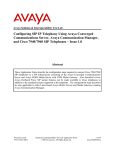
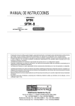
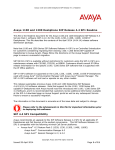
Avaya Solution & Interoperability Test Lab Application Notes for Avaya 1100- and 1200-Series IP Deskphones R3.2 with Avaya Aura™ Communication Manager R6, Avaya Aura™ Session Manager R6, and Avaya Modular Messaging R5.2 – Issue 1.0 Abstract These Application Notes describe a solution comprised of Avaya Aura™ Communication Manager, Avaya Aura™ Session Manager, Avaya Modular Messaging, and Avaya 1100- and 1200-Series IP Deskphones with SIP software. During testing, the IP Deskphones successfully registered with Session Manager, placed and received calls to and from SIP and non-SIP telephones, and executed other telephony features such as conference, transfer, hold, and OffPBX-Station (OPS) related features such as Call Pickup, Call Park, Whisper Page, and Transfer to Voice Mail. Information in these Application Notes has been obtained through interoperability testing and additional technical discussions, and was conducted at the Avaya Solution and Interoperability Test Lab at the request of Avaya 1100- and 1200-Series IP Deskphone Product Management. FS; Reviewed: SPOC 09/07/2010 Solution & Interoperability Test Lab Application Notes ©2010 Avaya Inc. All Rights Reserved. 1 of 44 11xx12xx-SM 1. Introduction These Application Notes describe a solution comprised of Avaya Aura™ Communication Manager, Avaya Aura™ Session Manager, Avaya Modular Messaging, and Avaya 1100- and 1200-Series IP Deskphones with SIP software (formerly known as Nortel 1100- and 1200-Series SIP Phones). These telephones were originally developed under the Nortel brand, and as such do not currently support the Avaya Advanced SIP Telephony (AST) protocol implemented in Avaya 9600 Series IP Telephones (SIP). Nevertheless, Communication Manager and Session Manager have the capability to extend some advanced telephony features to non-AST telephones. The configuration steps described include how to set up these features as well as the standard calling features supported by the phones. See Section 4 for a summary of the features supported. 2. Reference Configuration In the test configuration shown below, the Avaya S8800 Server with Avaya G450 Media Gateway is configured as an Evolution Server (CM-ES), and supports all of the telephones shown. The SIP telephone models tested included the 1120E (4 line monochrome), 1140E (6 line monochrome), 1165E (8 line color), 1220 (4 line monochrome), and the 1230 (10 line monochrome) running SIP firmware. The phones are directly registered to Session Manager and are supported by Communication Manager configured as an Evolution Server (CM-ES). Communication between Communication Manager and Avaya Modular Messaging is via Session Manager, which uses an adaptation module to translate subscriber numbers between the 5-digit extensions used by Communication Manager and the normalized 11-digit numbers used by Modular Messaging. Modular Messaging supports all telephones for voice messaging. Figure 1: Sample Configuration FS; Reviewed: SPOC 09/07/2010 Solution & Interoperability Test Lab Application Notes ©2010 Avaya Inc. All Rights Reserved. 2 of 44 11xx12xx-SM In general, a SIP telephone originates a call by sending a call request (SIP INVITE message) to Session Manager, which then routes the call over a SIP trunk to Communication Manager for origination services. If the call is destined for another local SIP telephone, Communication Manager routes the call back over the SIP trunk to Session Manager for delivery to the destination SIP telephone. If the call is destined for an H.323 or Digital telephone, then Communication Manager terminates the call directly. These application notes assume that Communication Manager and Session Manager are already installed and basic configuration steps have been performed. Only steps relevant to SIP telephone calling features will be described in this document. For further details on configuration steps not covered in this document, consult the appropriate document in Section 10. 3. Equipment and Software Validated The following equipment and software/firmware were used for the sample configuration provided. Equipment Avaya S8800 Server with G450 Media Gateway Software/Firmware Avaya Aura™ Communication Manager 6.0 Service Pack 0 (Load 345, Update 18246) Avaya Aura™ Session Manager 6.0, Load 600020 Avaya S8800 Server Avaya Aura™ System Manager 6.0, Load 600020 Avaya 9630 IP Telephone (SIP) 2.6.0.0 Avaya 9630 IP Telephone (H.323) 3.1.1 Avaya 1603 IP Telephone (SIP) R1.0.0 Avaya 6408D+ Digital Telephone Modular Messaging Storage Server 5.2, Service Pack 3 Patch 1 Modular Messaging Application Server 5.2, Service Pack 3 Patch 1 Avaya 1100-series IP deskphones (SIP) 03.02.15.05 Avaya 1200-series IP deskphones (SIP) 03.02.15.05 Table 1: Equipment and Software/Firmware FS; Reviewed: SPOC 09/07/2010 Solution & Interoperability Test Lab Application Notes ©2010 Avaya Inc. All Rights Reserved. 3 of 44 11xx12xx-SM 4. Calling Features 4.1. Overview Table 2 below shows the calling features successfully tested. Notes on specific feature operations are included in Section 4.2. In addition to basic calling capabilities, the Internet Engineering Task Force (IETF) has defined a supplementary set of calling features in RFC 5359 [13], previously referred to as the SIPPING features. This provides a useful framework to describe product capabilities and compare features supported by various equipment vendors. Communication Manager can support many of these features if the telephone can not locally support them. In addition, features beyond those specified in RFC 5359 can be extended to the telephone using Communication Manager configured as an Evolution Server. SUPPORTED FEATURES Basic Calling features Extension to extension call Basic call to non-SIP phones Intercept tones/displays Mute Redial Call Waiting Do Not Disturb Speed Dial buttons Redial from call logs Compressed codecs Message Waiting Support SIPPING (RFC 5359) Features Call Hold Consultation Hold Music on Hold Unattended Transfer Attended Transfer Call Forward Unconditional Call Forward Busy Call Forward No Answer 3-way conference - 3rd party added 3-way conference - 3rd party joins Find-Me Incoming Call Screening Outgoing Call Screening Call Park/Unpark Call Pickup Additional Station-Side Features Calling Name/Number Block Directed Call Pick-Up Priority Call Transfer to Voice Mail Whisper Page COMMENTS Reorder with message Section 4.2.1 G.729A, G.729AB, G.722-64k Sections 4.2.2, 5.8 Via FNE (Section 5.8) Via FNE (Section 5.8) Modular Messaging “Find Me” feature Via Class Of Restriction (Section 5.9) Via Class Of Restriction (Section 5.9) Via FNE (Section 5.8) Via FNE (Section 5.8) Via FNE (Section 4.2.3, 5.8, 7.4) Via FNE (Section 5.8) Via FNE (Sections 4.2.4, 5.8, 5.9) Via FNE (Section 5.8) Via FNE (Section 5.8) Table 2: SIP Telephony Feature Support FS; Reviewed: SPOC 09/07/2010 Solution & Interoperability Test Lab Application Notes ©2010 Avaya Inc. All Rights Reserved. 4 of 44 11xx12xx-SM Some supported features shown in Table 2 can be invoked by dialing a Feature Name Extension (FNE). Or, a speed dial button on the telephone can be programmed to an FNE. Communication Manager automatically handles many other standard features such as call coverage, trunk selection using Automatic Alternate Routing (AAR) and Automatic Route Selection (ARS), Class Of Service/Class Of Restriction (COS/COR), and voice messaging. Details on operation and administration for Communication Manager can be found in References [4-6]. 4.2. Operational Notes 4.2.1. Do Not Disturb When Do Not Disturb is activated, the call is not presented to or displayed on the phone. The call follows the coverage path configured for the extension in Communication Manager. This feature is locally supported by the telephone, and is recommended instead of the Communication Manager FNEs for Send All Calls and Send All Calls Cancel. 4.2.2. Call Forward Unconditional It is recommended that this feature be administered as a Communication Manager FNE rather than using the local call forward of the telephone. The user of local call forward will not benefit from any of the call coverage features available in Communication Manager, including coverage to voice messaging. 4.2.3. Calling Name/Number Block The Avaya 1100- and 1200-Series IP Deskphones support privacy by means of the RemoteParty-ID SIP header in the INVITE message. Since Communication Manager supports the newer Privacy header along with P-Asserted-Identity header, this local feature is not supported. It is recommended that the Calling Number Block FNE in Communication Manager be used instead. This can be configured as speed dial button on the telephone (see Sections 5.8 and 7.4). 4.2.4. Priority Call The telephone may originate priority calls based on the class of service administered for it (see Section 5.9) or if the user dials the appropriate FNE. Note however, that it will not indicate a received priority call. Avaya 9600 Series IP Telephones (SIP, H.323) and Avaya 6408D+ Digital Telephones will properly indicate them via distinctive ringing and calling party display. FS; Reviewed: SPOC 09/07/2010 Solution & Interoperability Test Lab Application Notes ©2010 Avaya Inc. All Rights Reserved. 5 of 44 11xx12xx-SM 5. Configure Avaya Aura™ Communication Manager This section describes a procedure for setting up a SIP trunk between Communication Manager serving as an Evolution Server and Session Manager. This includes steps for setting up IP codecs, an IP network region, SIP signaling group, SIP trunk group, dial plan, class of service, class of restriction, and call routing. Also, a procedure is described here to configure SIP telephones and features available with OPS in Communication Manager. Configuration in the following sections focuses on the fields where a value needs to be entered or modified. Default values are used for all other fields. These steps are performed from the Communication Manager System Access Terminal (SAT) interface. Avaya and third party SIP telephones are configured as Off-PBX Stations (OPS) in Communication Manager. Communication Manager does not directly control an OPS endpoint, but its features and calling privileges can be applied to it by associating a local extension with the OPS endpoint. Similarly, a SIP telephone in Session Manager is associated with an extension on Communication Manager. SIP telephones register with Session Manager and use Communication Manager for call origination and termination services, including Feature Name Extension (FNE) support. Enter the save translation command after completing this section. 5.1. Capacity Verification Before a SIP trunk or OPS endpoints can be configured, it is necessary to verify if there is enough capacity. Step Description 1. Enter the display system-parameters customer-options command. Verify that there are sufficient Maximum Off-PBX Telephones – OPS licenses. If not, contact an authorized Avaya account representative to obtain additional licenses. display system-parameters customer-options OPTIONAL FEATURES G3 Version: V16 Location: A Platform: 28 Page 1 of 11 Software Package: Enterprise System ID (SID): 1 Module ID (MID): 1 Platform Maximum Ports: Maximum Stations: Maximum XMOBILE Stations: Maximum Off-PBX Telephones - EC500: Maximum Off-PBX Telephones OPS: Maximum Off-PBX Telephones - PBFMC: Maximum Off-PBX Telephones - PVFMC: Maximum Off-PBX Telephones - SCCAN: Maximum Survivable Processors: 65000 36000 41000 36000 36000 36000 36000 0 313 USED 296 124 0 1 101 0 0 0 0 (NOTE: You must logoff & login to effect the permission changes.)display systemparameters customer-options FS; Reviewed: SPOC 09/07/2010 Solution & Interoperability Test Lab Application Notes ©2010 Avaya Inc. All Rights Reserved. 6 of 44 11xx12xx-SM 2. Proceed to Page 2 of the OPTIONAL FEATURES form. Verify that the number of Maximum Administered SIP Trunks supported by the system is sufficient for the number of SIP trunks needed. If not, contact an authorized Avaya account representative to obtain additional licenses. Note: Each SIP call between two SIP endpoints requires two SIP trunks for the duration of the call. The license file installed on the system controls the maximum permitted. display system-parameters customer-options OPTIONAL FEATURES Page IP PORT CAPACITIES Maximum Administered H.323 Trunks: Maximum Concurrently Registered IP Stations: Maximum Administered Remote Office Trunks: Maximum Concurrently Registered Remote Office Stations: Maximum Concurrently Registered IP eCons: Max Concur Registered Unauthenticated H.323 Stations: Maximum Video Capable Stations: Maximum Video Capable IP Softphones: Maximum Administered SIP Trunks: Maximum Administered Ad-hoc Video Conferencing Ports: Maximum Number of DS1 Boards with Echo Cancellation: Maximum TN2501 VAL Boards: Maximum Media Gateway VAL Sources: Maximum TN2602 Boards with 80 VoIP Channels: Maximum TN2602 Boards with 320 VoIP Channels: Maximum Number of Expanded Meet-me Conference Ports: FS; Reviewed: SPOC 09/07/2010 12000 18000 12000 18000 414 100 18000 18000 24000 24000 522 128 250 128 128 300 Solution & Interoperability Test Lab Application Notes ©2010 Avaya Inc. All Rights Reserved. 2 of 11 USED 0 11 0 0 0 0 0 0 172 0 0 0 1 0 0 0 7 of 44 11xx12xx-SM 5.2. IP Codec Set This section describes the steps for administering an IP codec set, which is used in the IP network region when Communication Manager communicates with the SIP telephones via Session Manager. Step Description 1. Enter the change ip-codec-set n command, where n is a number between 1 and 7, inclusive. IP codec sets are used in Section 5.3 for configuring an IP network region to specify which codec sets may be used within and between network regions. For the compliance testing, G.722-64K, G.711MU, G.729A, and G.729AB were tested. If only one codec should be used, then only specify the one that is to be used. Note: for G.729 interoperability between Avaya 1100- and 1200-Series IP Deskphones and Avaya 9600 Series SIP Telephones, the configuration file settings for all telephones should match that in the IP codec set. For the sample configuration shown below, the 9600 SIP Telephone configuration file should include the line: SET ENABLE_G729 “2”, and the 1100- and 1200-Series IP Deskphone configuration files should include the line “G729_ENABLE_ANNEXB YES”. See References [7, 8] and Section 7.2. change ip-codec-set 1 Page 1 of 2 IP Codec Set Codec Set: 1 Audio Codec 1: G.722-64K 2: G.711MU 3: G.729AB 4: FS; Reviewed: SPOC 09/07/2010 Silence Suppression n n Frames Per Pkt 2 2 2 Packet Size(ms) 20 20 20 Solution & Interoperability Test Lab Application Notes ©2010 Avaya Inc. All Rights Reserved. 8 of 44 11xx12xx-SM 5.3. IP Network Region This section describes the steps for administering an IP network region, which is used when Communication Manager communicates with the SIP telephones via Session Manager. Step Description 1. Enter the change ip-network-region n command, where n is a number between 1 and 250 inclusive and configure the following as shown in the display screen below: Authoritative Domain – Set to avaya.com for the sample configuration. This should match the SIP Domain value configured in Session Manager. Intra-region IP-IP Direct Audio – Set to yes to allow direct IP-to-IP audio connectivity between endpoints registered to Communication Manager or Session Manager in the same IP network region. Inter-region IP-IP Direct Audio – Set to yes to allow direct IP-to-IP audio connectivity between endpoints registered to Communication Manager or Session Manager in different IP network regions. Codec Set – Set the codec set number as provisioned in Section 5.2. change ip-network-region 1 Page 1 of 20 IP NETWORK REGION Region: 1 Location: Authoritative Domain: avaya.com Name: CM and SIP Phones MEDIA PARAMETERS Intra-region IP-IP Direct Audio: Codec Set: 1 Inter-region IP-IP Direct Audio: UDP Port Min: 2048 IP Audio Hairpinning? UDP Port Max: 65535 DIFFSERV/TOS PARAMETERS Call Control PHB Value: 0 Audio PHB Value: 46 Video PHB Value: 26 802.1P/Q PARAMETERS Call Control 802.1p Priority: 6 Audio 802.1p Priority: 6 Video 802.1p Priority: 5 AUDIO RESOURCE RESERVATION yes yes y PARAMETERS 5.4. IP Node Names This section describes the steps for administering a node name for Session Manager to be used in the configuration of the SIP signaling group. Step Description 1. Use the change node-names ip command to add a new node name for Session Manager. change node-names ip Page 1 of 2 IP NODE NAMES Name SM1 default procr procr6 FS; Reviewed: SPOC 09/07/2010 IP Address 10.1.2.70 0.0.0.0 10.1.2.90 :: Solution & Interoperability Test Lab Application Notes ©2010 Avaya Inc. All Rights Reserved. 9 of 44 11xx12xx-SM 5.5. SIP Signaling Group This section describes the steps for administering a signaling group for communication between Communication Manager and Session Manager. Step Description 1. Enter the command add signaling-group n, where n is an available signaling group and configure the following as shown in the display screen below: Group Type – Set to sip. Transport Method – Set to tls. IMS Enabled – Set to n. Near-end Node Name - Set to procr. Near-end Listen Port - Defaults to 5061 for TLS. Far-end Node Name - Set to the node name configured in Section 5.4. Far-end Listen Port - Defaults to 5061 for TLS. Far-end Network Region - Set to the Region configured in Section 5.3. Far-end Domain - Set to avaya.com for the sample configuration. This should match the SIP Domain value configured in Session Manager. Direct IP-IP Audio Connections – Set to y. add signaling-group 60 Page 1 of 1 SIGNALING GROUP Group Number: 60 Group Type: sip IMS Enabled? n Transport Method: tls Q-SIP? n IP Video? n Peer Detection Enabled? y Peer Server: Near-end Node Name: procr Near-end Listen Port: 5061 SIP Enabled LSP? n Enforce SIPS URI for SRTP? y Far-end Node Name: SM1 Far-end Listen Port: 5061 Far-end Network Region: 1 Far-end Domain: avaya.com Incoming Dialog Loopbacks: eliminate DTMF over IP: rtp-payload Session Establishment Timer(min): 3 Enable Layer 3 Test? n H.323 Station Outgoing Direct Media? n FS; Reviewed: SPOC 09/07/2010 Bypass If IP Threshold Exceeded? RFC 3389 Comfort Noise? Direct IP-IP Audio Connections? IP Audio Hairpinning? Initial IP-IP Direct Media? Alternate Route Timer(sec): Solution & Interoperability Test Lab Application Notes ©2010 Avaya Inc. All Rights Reserved. n n y n n 10 10 of 44 11xx12xx-SM 5.6. SIP Trunk Group This section describes the steps for administering a trunk group for communication between Communication Manager and Session Manager. Step Description 1. Issue the command add trunk-group n, where n is an unallocated trunk group and configure the following as shown in the display screen below: Group Type – Set to the Group Type field to sip. Group Name – Enter any descriptive name. TAC (Trunk Access Code) – Set to any available trunk access code. Service Type – Set to tie. Signaling Group – Set to the Group Number field value configured in Section 5.5. (i.e., 60) Number of Members – Allowed values are between 0 and 255. Set to a value large enough to accommodate the number of SIP telephone extensions being used. Note: Each SIP call between two SIP endpoints (whether internal or external) requires two SIP trunk members for the duration of the call. The license file installed on the system controls the maximum permitted. add trunk-group 60 Page 1 of 21 TRUNK GROUP Group Number: Group Name: Direction: Dial Access? Queue Length: Service Type: 2. 60 SM1 two-way n 0 tie Group Type: sip CDR Reports: y COR: 1 TN: 1 TAC: 160 Outgoing Display? n Night Service: Auth Code? n Member Assignment Method: auto Signaling Group: 60 Number of Members: 120 Proceed to Page 3 and set Numbering Format to private. change trunk-group 60 TRUNK FEATURES ACA Assignment? n Page 3 of 21 Measured: none Maintenance Tests? y Numbering Format: private UUI Treatment: service-provider Replace Restricted Numbers? n Replace Unavailable Numbers? N FS; Reviewed: SPOC 09/07/2010 Solution & Interoperability Test Lab Application Notes ©2010 Avaya Inc. All Rights Reserved. 11 of 44 11xx12xx-SM 5.7. Define System Features This section describes the steps for administering system wide call features and options related to OPS in Communication Manager. Step Description 1. Use the change system-parameters features command and navigate to Page 18 to administer system wide features for the SIP telephones. Those related to features listed in Table 2 are shown outlined in red. These are all standard Communication Manager features. change system-parameters features FEATURE-RELATED SYSTEM PARAMETERS Page 18 of 19 Page 19 of 19 INTERCEPT TREATMENT PARAMETERS Invalid Number Dialed Intercept Treatment: tone Invalid Number Dialed Display: Restricted Number Dialed Intercept Treatment: tone Restricted Number Dialed Display: Intercept Treatment On Failed Trunk Transfers? n WHISPER PAGE Whisper Page Tone Given To: paged change system-parameters features FEATURE-RELATED SYSTEM PARAMETERS IP PARAMETERS Direct IP-IP Audio Connections? y IP Audio Hairpinning? y Synchronization over IP? n CALL PICKUP Maximum Number of Digits for Directed Group Call Pickup: 4 Call Pickup on Intercom Calls? y Call Pickup Alerting? n Temporary Bridged Appearance on Call Pickup? y Directed Call Pickup? y Extended Group Call Pickup: simple Enhanced Call Pickup Alerting? N FS; Reviewed: SPOC 09/07/2010 Solution & Interoperability Test Lab Application Notes ©2010 Avaya Inc. All Rights Reserved. 12 of 44 11xx12xx-SM 5.8. Define the Dial Plan This section describes the steps for administering the dial plan, including overall dial plan format, Feature Access Codes (FACs), and Feature Name Extensions (FNEs). Step Description 1. Use the change dialplan analysis command to define the dial plan formats used in the system. This includes all telephone extensions, Feature Name Extensions (FNEs), and Feature Access Codes (FACs). To define the FNEs for the features listed in Table 2, a Feature Access Code (FAC) must also be specified for the corresponding feature. In the sample configuration, telephone extensions are five digits long and begin with 3, FNEs are five digits beginning with 7, and the FACs have formats as indicated with Call Type “fac”. Note: a FAC of “8” was used for AAR routing by a voice mail hunt group, the configuration for which is not included in these Application Notes. See Reference [11] for more information. change dialplan analysis Page DIAL PLAN ANALYSIS TABLE Location: all Dialed String 0 1 2 3 4 5 6 7 8 9 * # 2. Total Call Length Type 3 fac 3 dac 5 ext 5 ext 5 ext 5 ext 3 fac 5 ext 1 fac 1 fac 2 fac 2 fac Dialed String Total Call Length Type 1 of 12 Percent Full: 2 Dialed String Total Call Length Type Use the change private-numbering command to add an entry as shown below for the calling extensions that will be using the trunk to Session Manager. The entry specifies the format that the calling number will have in outgoing calls. Set Ext Len to the length of the calling extensions, Ext Code to an initial set of digits that covers the extension range, Trk Grp(s) to the trunk group number defined in Section 5.6, and Total Len to the length of the calling extensions. In the sample configuration, the extension is sent unchanged. Note: if the Trk Grp(s) field is left blank, as in the first entry, this formatting will be applied to all trunk groups in the system. change private-numbering 0 Page 1 of 2 NUMBERING - PRIVATE FORMAT Ext Len 5 5 5 Ext Code 2 3 4 FS; Reviewed: SPOC 09/07/2010 Trk Grp(s) 60 60 Private Prefix Total Len 5 Total Administered: 3 5 Maximum Entries: 540 5 Solution & Interoperability Test Lab Application Notes ©2010 Avaya Inc. All Rights Reserved. 13 of 44 11xx12xx-SM 3. Use change feature-access-codes to define the access codes for the FNEs highlighted in red. The following screens have been abbreviated to highlight those FACs involved in supporting the FNEs and the AAR FAC. change feature-access-codes Page 1 of FEATURE ACCESS CODE (FAC) Answer Back Access Code: 625 Attendant Access Code: Auto Alternate Routing (AAR) Access Code: 8 Auto Route Selection (ARS) - Access Code 1: 9 Access Code 2: Automatic Callback Activation: *5 Deactivation: #5 Call Forwarding Activation Busy/DA: *2 All: 612 Deactivation: #2 Call Forwarding Enhanced Status: Act: Deactivation: Call Park Access Code: 624 Call Pickup Access Code: *6 CAS Remote Hold/Answer Hold-Unhold Access Code: #6 10 change feature-access-codes 10 Page 2 of FEATURE ACCESS CODE (FAC) Contact Closure Pulse Code: Directed Call Pickup Access Code: 654 Directed Group Call Pickup Access Code: Emergency Access to Attendant Access Code: EC500 Self-Administration Access Codes: Enhanced EC500 Activation: 660 Enterprise Mobility User Activation: Extended Call Fwd Activate Busy D/A All: Extended Group Call Pickup Access Code: 641 Deactivation: 661 Deactivation: Deactivation: change feature-access-codes Page 3 of 10 FEATURE ACCESS CODE (FAC) PASTE (Display PBX data on Phone) Access Code: Personal Station Access (PSA) Associate Code: Per Call CPN Blocking Code Access Code: Per Call CPN Unblocking Code Access Code: Posted Messages Activation: Priority Calling Access Code: Program Access Code: Dissociate Code: 615 616 Deactivation: *7 *0 Refresh Terminal Parameters Access Code: 694 Remote Send All Calls Activation: Self Station Display Activation: Send All Calls Activation: *3 Station Firmware Download Access Code: Deactivation: Deactivation: #3 change feature-access-codes Page 4 of 10 FEATURE ACCESS CODE (FAC) Transfer to Voice Mail Access Code: #9 Trunk Answer Any Station Access Code: User Control Restrict Activation: 691 Voice Coverage Message Retrieval Access Code: Voice Principal Message Retrieval Access Code: Whisper Page Activation Access Code: 620 FS; Reviewed: SPOC 09/07/2010 Deactivation: 692 Solution & Interoperability Test Lab Application Notes ©2010 Avaya Inc. All Rights Reserved. 14 of 44 11xx12xx-SM 4. FNEs are defined using the change off-pbx-telephone feature-name-extensions set n command, where n is a number between 1 and 99 and will default to 1 if n is not specified. This command is used to support both SIP telephones and Extension to Cellular. The highlighted fields correspond to those features listed as supported in Table 2. The fields that have been left blank correspond to those more appropriate for Extension to Cellular. change off-pbx-telephone feature-name-extensions set 1 EXTENSIONS TO CALL WHICH ACTIVATE FEATURES BY NAME Set Name: Active Appearance Select: Automatic Call Back: Automatic Call-Back Cancel: Call Forward All: Call Forward Busy/No Answer: Call Forward Cancel: Call Park: Call Park Answer Back: Call Pick-Up: Calling Number Block: Calling Number Unblock: Conditional Call Extend Enable: Conditional Call Extend Disable: Conference Complete: Conference on Answer: Directed Call Pick-Up: Drop Last Added Party: FS; Reviewed: SPOC 09/07/2010 1 of 2 Page 2 of 2 70030 70003 70004 70005 70006 70007 70008 70009 70010 70012 70013 70011 70014 70015 change off-pbx-telephone feature-name-extensions set 1 EXTENSIONS TO CALL WHICH ACTIVATE FEATURES BY NAME Exclusion (Toggle On/Off): Extended Group Call Pickup: Held Appearance Select: Idle Appearance Select: Last Number Dialed: Malicious Call Trace: Malicious Call Trace Cancel: Off-Pbx Call Enable: Off-Pbx Call Disable: Priority Call: Recall: Send All Calls: Send All Calls Cancel: Transfer Complete: Transfer On Hang-Up: Transfer to Voice Mail: Whisper Page Activation: Page 70016 70025 70017 70019 70029 70021 70027 70028 70000 70001 70002 70022 70023 70026 Solution & Interoperability Test Lab Application Notes ©2010 Avaya Inc. All Rights Reserved. 15 of 44 11xx12xx-SM 5.9. Specify Class of Service (COS) and Class Of Restriction (COR) This section describes the steps for administering the COS and COR, which affects what calling features and feature options are permitted for defined groups of telephone users. Step Description 1. Use the change cos-group n command, where n is a class of service group number, to set the appropriate service permissions to support the corresponding features (shown in outlined in red). For the sample configuration, COS group 1 was used. On Page 2, set the value of VIP Caller to “y” only if all calls made by telephones with this COS should be priority calls. Note that priority can be requested on a call-by-call basis by using the Priority Call FNE (see Section 5.8). Priority call indication (e.g., distinctive ring and display of “Priority”) is only supported on Avaya Digital and 9600 Series IP telephones (H.323 and SIP). change cos-group 1 CLASS OF SERVICE Page COS Group: 1 Auto Callback Call Fwd-All Calls Data Privacy Priority Calling Console Permissions Off-hook Alert Client Room Restrict Call Fwd-Off Net Call Forwarding Busy/DA Personal Station Access (PSA) Extended Forwarding All Extended Forwarding B/DA Trk-to-Trk Transfer Override QSIG Call Offer Originations Contact Closure Activation 0 n n n n y n n n n n n n n n n 1 y y n y y n n n y n y y y n n 1 of 2 COS Name: 2 y y n n y n n y n n n n n n n 3 n y y n n n n y n n n n n n n 4 y y n n n n n y n n n n n n n 5 n n y n n n n y n n n n n n n 6 y n y n n n n y n n n n n n n 7 n y y n n n n y n n n n n n n 8 y y y n n n n y n n n n n n n 9 n n n y n n n y n n n n n n n 10 y n n y n n n y n n n n n n n change cos-group 1 11 n y n y n n n y n n n n n n n 12 y y n y n n n y n n n n n n n Page 13 n n y y n n n y n n n n n n n 14 y n y y n n n y n n n n n n n 2 of 15 n n y n n n n y n n n n n n n 2 CLASS OF SERVICE VIP Caller 0 n 1 n 2 3 4 5 6 7 8 9 10 11 12 13 14 15 n n n n n n n n n n n n n n Masking CPN/Name Override Call Forwarding Enhanced Priority Ip Video Ad-hoc Video Conferencing n y n n n y n n n y n n FS; Reviewed: SPOC 09/07/2010 n y n n n y n n n y n n n y n n n y n n n y n n Solution & Interoperability Test Lab Application Notes ©2010 Avaya Inc. All Rights Reserved. n y n n n y n n n y n n n y n n n y n n n y n n n y n n 16 of 44 11xx12xx-SM 2. Use the change cor n command, where n is a class of restriction number, to enable applicable calling features. To use the Directed Call Pickup feature, the Can Use Directed Call Pickup and Can Be Picked Up By Directed Call Pickup fields must be set to “y” for the affected stations. In the sample configuration, the telephones were assigned to COR 1. Note that Page 4 can be used to implement a form of centralized call screening for groups of stations and trunks. change cor 1 Page 1 of 23 CLASS OF RESTRICTION COR Number: 1 COR Description: Trunk FRL: Can Be Service Observed? Can Be A Service Observer? Time of Day Chart: Priority Queuing? Restriction Override: Restricted Call List? 0 y y 1 n none n APLT? Calling Party Restriction: Called Party Restriction: Forced Entry of Account Codes? Direct Agent Calling? Facility Access Trunk Test? Can Change Coverage? Access to MCT? y Fully Restricted Service? Group II Category For MFC: 7 Hear VDN of Origin Annc.? Send ANI for MFE? n Add/Remove Agent Skills? MF ANI Prefix: Automatic Charge Display? Hear System Music on Hold? y PASTE (Display PBX Data on Phone)? Can Be Picked Up By Directed Call Pickup? Can Use Directed Call Pickup? Group Controlled Restriction: change cor 1 y none none n y n n n n n n n y y inactive Page 4 of 23 CLASS OF RESTRICTION CALLING PERMISSION (Enter "y" to grant permission to call specified COR) 0? 1? 2? 3? 4? 5? 6? 7? 8? 9? 10? 11? 12? 13? y y y y y y y y y y n y y y FS; Reviewed: SPOC 09/07/2010 15? 16? 17? 18? 19? 20? 21? 22? 23? 24? 25? 26? 27? 28? y y y y y y y y y y y y y y 30? 31? 32? 33? 34? 35? 36? 37? 38? 39? 40? 41? 42? 43? y y y y y y y y y y y y y y 44? 45? 46? 47? 48? 49? 50? 51? 52? 53? 54? 55? 56? 57? y y y y y y y y y y y y y y 58? 59? 60? 61? 62? 63? 64? 65? 66? 67? 68? 69? 70? 71? y y y y y y y y y y y y y y 72? 73? 74? 75? 76? 77? 78? 79? 80? 81? 82? 83? 84? 85? Solution & Interoperability Test Lab Application Notes ©2010 Avaya Inc. All Rights Reserved. y y y y y y y y y y y y y y 86? 87? 88? 89? 90? 91? 92? 93? 94? 95? 96? 97? 98? 99? y y y y y y y y y y y y y y 17 of 44 11xx12xx-SM 5.10. SIP Stations This section describes the steps for administering OPS stations in Communication Manager and associating the OPS station extensions with the telephone numbers of the Avaya 1100-and 1200Series IP Deskphones. The configuration is the same for all phones except for the desired number of call appearances as detailed in Step 3. Note that the corresponding users must be configured in Session Manager. There are two methods to sequence these steps: 1. Configure the station and off-PBX-station forms for each user in Communication Manager. Then configure the corresponding user in Session Manager, being sure to check the “Use Existing Stations” box (see Section 6). 2. Configure the user in Session Manager, being sure to leave the “Use Existing Stations” box unchecked (see Section 6). Session Manager will automatically generate the corresponding station and off-PBX-station information in Communication Manager. Then use the change station command in Communication Manager to add other configuration data, such as Coverage Path, MWI Served User Type, and additional call appearances, if needed. Method 2 was used in the sample configuration. For method 1, perform the following steps for each user; then follow the steps in Section 6. For method 2, follow the steps in Section 6 first; then use change station n to modify any station parameters as described below using the station form in this section as a guide. FS; Reviewed: SPOC 09/07/2010 Solution & Interoperability Test Lab Application Notes ©2010 Avaya Inc. All Rights Reserved. 18 of 44 11xx12xx-SM Step Description 1. Enter the add station n command, where n is an available extension in the dial plan, to administer an OPS station. On Page 1 of the form configure the following fields as shown in the display screen below: Type – Set to 9630SIP. Port – Leave blank. (Once the form is submitted, a virtual port is assigned, e.g., S00022) Name – Enter any descriptive name. Coverage Path – Enter the coverage path number defined for this telephone (e.g., for coverage to voice mail). add station 30043 Page 1 of 6 STATION Extension: 30043 Type: 9630SIP Port: Name: 1165E Lock Messages? n Security Code: Coverage Path 1: 60 Coverage Path 2: Hunt-to Station: BCC: 0 TN: 1 COR: 1 COS: 1 STATION OPTIONS Time of Day Lock Table: Loss Group: 19 Message Lamp Ext: 30043 Display Language: english Survivable COR: internal Survivable Trunk Dest? y Button Modules: 0 IP SoftPhone? n IP Video? N FS; Reviewed: SPOC 09/07/2010 Solution & Interoperability Test Lab Application Notes ©2010 Avaya Inc. All Rights Reserved. 19 of 44 11xx12xx-SM 2. Proceed to Page 2 of the form. Set MWI Served User Type to sip-adjunct. add station 30043 Page 2 of 6 STATION FEATURE OPTIONS LWC Reception: spe LWC Activation? y Coverage Msg Retrieval? Auto Answer: Data Restriction? Idle Appearance Preference? Bridged Idle Line Preference? CDR Privacy? n Per Button Ring Control? n Bridged Call Alerting? n Active Station Ringing: single H.320 Conversion? n y none n n n Per Station CPN - Send Calling Number? EC500 State: enabled MWI Served User Type: sip-adjunct Coverage After Forwarding? s Direct IP-IP Audio Connections? y Always Use? n IP Audio Hairpinning? N Emergency Location Ext: 30043 3. Proceed to Page 4 of the form and add the desired number of call-appr entries in the BUTTON ASSIGNMENTS section. This governs how many concurrent calls can be supported. Avaya 1100-Series IP Deskphones have the capability of handling 11 call appearances (10 for the 1200-Series), but display only one local call appearance button when idle (see display in Section 7.4 Step 3). So the number of entries shown below are not required to match that displayed on the telephone. Three are configured here to support conferencing scenarios. add station 30043 Page 4 of 6 STATION SITE DATA Room: Jack: Cable: Floor: Building: Headset? Speaker? Mounting: Cord Length: Set Color: ABBREVIATED DIALING List1: BUTTON ASSIGNMENTS 1: call-appr 2: call-appr 3: call-appr 4: FS; Reviewed: SPOC 09/07/2010 List2: n n d 0 List3: 5: 6: 7: 8: Solution & Interoperability Test Lab Application Notes ©2010 Avaya Inc. All Rights Reserved. 20 of 44 11xx12xx-SM 4. Enter the change off-pbx-telephone station-mapping command and configure the following as shown in the screen below: Station Extension – Set the extension of the OPS station as configured above. Application – Set to OPS. Phone Number – Enter the number that the SIP telephone will use for registration and call termination. In the sample configuration, the Phone Number is the same as the Station Extension. Trunk Selection – Set to aar. change off-pbx-telephone station-mapping 30043 STATIONS WITH OFF-PBX TELEPHONE INTEGRATION Station Extension 30043 5. Application Dial CC Prefix OPS - Phone Number Trunk Selection aar 30043 1 of Config Set 1 3 Dual Mode If it is desired to support more than three call appearances, then proceed to Page 2 and enter the desired number for Call Limit. Remember that this number should agree with the number of call-appr entries in the station form (Step 3). change off-pbx-telephone station-mapping 30043 STATIONS WITH OFF-PBX TELEPHONE INTEGRATION Station Extension 30043 6. Page Appl Name OPS Call Limit 3 Mapping Mode both Calls Allowed all Page 2 of Bridged Calls both 3 Location Repeat Steps 1 - 5 as necessary to administer additional OPS stations and associations for the SIP telephones. 5.11. Routing Step Description 1. Enter the change aar analysis n command, where n is the number to be routed; in this case 300 (matching any extensions starting with 300xx). On Page 1 of the form configure the following fields as shown in the screen below: Dialed String – Set to 300. Total Min/Max – Set to 5 Route Patten - Set to the appropriate route pattern, in this case 60. Call Type – Set to unku. change aar analysis 3 Page AAR DIGIT ANALYSIS TABLE Location: all Dialed String 300 FS; Reviewed: SPOC 09/07/2010 Total Min Max 5 5 Route Pattern 60 Call Type unku 1 of 2 Percent Full: 0 Node Num ANI Reqd n Solution & Interoperability Test Lab Application Notes ©2010 Avaya Inc. All Rights Reserved. 21 of 44 11xx12xx-SM 2. Enter the change route-pattern n command, where n is the route-pattern to be configured, in this case 60. On Page 1 of the form configure the following fields as shown in the screen below: Pattern name – Set to an appropriate name. Grp No – Set to the trunk group being used, in this case 60 (see Section 5.6). FRL – Set to 0 (lowest restriction, or a higher number if appropriate). No. Del Dgts - Set to 0 (all digits are being sent). LAR – Set to next for the first row. This recommended so that in the case of network failures, the shorter Alternate Route Timer (10 seconds) will be used as the time-out value rather than the Session Establishment Timer (3 minutes), before reorder feedback is provided to the caller. These timers are specified on the SIP signaling form (See Section 5.5). change route-pattern 60 Pattern Number: 60 Pattern Name: SM ES SCCAN? n Secure SIP? n Grp FRL NPA Pfx Hop Toll No. Inserted No Mrk Lmt List Del Digits Dgts 1: 60 0 0 2: 3: 4: 5: 6: 1: 2: 3: 4: 5: 6: BCC VALUE TSC CA-TSC 0 1 2 M 4 W Request ITC BCIE Service/Feature PARM y y y y y y rest rest rest rest rest rest y y y y y y FS; Reviewed: SPOC 09/07/2010 y y y y y y y y y y y y y y y y y y n n n n n n n n n n n n Solution & Interoperability Test Lab Application Notes ©2010 Avaya Inc. All Rights Reserved. Page 1 of 3 DCS/ IXC QSIG Intw n user n user n user n user n user n user No. Numbering LAR Dgts Format Subaddress next none none none none none 22 of 44 11xx12xx-SM 6. Configure Avaya Aura™ Session Manager This section describes the administration of SIP telephones in Session Manager. It is assumed that a trunk has already been provisioned that matches the Communication Manager configuration in Sections 5.5 and 5.6. For additional references in configuring SIP trunking between Communication Manager and Session Manager see References [4-6, 11-12]. The following screens show a sample configuration for an Avaya 1165E IP Deskphone whose extension is 30043. The same procedure can be followed for the other telephone models. Session Manager is configured via Avaya Aura™ System Manager. Use a web browser and enter “https://<ip-address>/SMGR, where <ip-address> is the IP address of System Manager. Log in using the appropriate credentials. On the main configuration page, select Manage Users under Users on the left menu, and click New to administer a new telephone user. This will create a new User Profile. In the General section, enter a Last Name and First Name. Note that fields marked with * are required to be filled in. The following screen shows what was entered for extension 30043. FS; Reviewed: SPOC 09/07/2010 Solution & Interoperability Test Lab Application Notes ©2010 Avaya Inc. All Rights Reserved. 23 of 44 11xx12xx-SM In the Identity section, enter a Login Name, for example [email protected], and the required passwords. Note that the Shared Communication Profile Password is the one the telephone is required to use when registering to Session Manager. It is also recommended to enter the display names. The Localized Display Name is what is displayed on a telephone when a call is made.1 SMGR Login Password, while required, was not used in this sample configuration, and can be any value. The information below is what was entered for extension 30043. Note that the passwords are not displayed when viewing an endpoint’s configuration. 1 When using Method 2 to configure telephone users (see Section 5.10), Session Manager uses this field to populate the Name field in the station form in Communication Manager. FS; Reviewed: SPOC 09/07/2010 Solution & Interoperability Test Lab Application Notes ©2010 Avaya Inc. All Rights Reserved. 24 of 44 11xx12xx-SM In the Communication Profile section, there are three sub-sections that need to be filled in: Communication Address, Session Manager Profile, and Endpoint Profile. Clicking on the arrow next to Communication Profile reveals the other sections. Click New under Communication Address. FS; Reviewed: SPOC 09/07/2010 Solution & Interoperability Test Lab Application Notes ©2010 Avaya Inc. All Rights Reserved. 25 of 44 11xx12xx-SM Set Type to Avaya SIP, and fill in the extension portion of the Fully Qualified Address, e.g., 30043. Select the SIP domain configured in Session Manager from the drop-down menu to the right of @. In the sample configuration, the domain is avaya.com. Then click Add. This will move the entry to the table as shown in the next screen. FS; Reviewed: SPOC 09/07/2010 Solution & Interoperability Test Lab Application Notes ©2010 Avaya Inc. All Rights Reserved. 26 of 44 11xx12xx-SM Click on the Session Manager Profile checkbox to expand that section. Click on the pull-down menu next to Primary Session Manager, and select the appropriate Session Manager instance from the list. Select the appropriate Origination and Termination Application Sequence. In the sample configuration, these sequences are those associated with the Communication Manager Evolution Server. Select the desired Home Location. The screen below shows what was used for extension 30043. FS; Reviewed: SPOC 09/07/2010 Solution & Interoperability Test Lab Application Notes ©2010 Avaya Inc. All Rights Reserved. 27 of 44 11xx12xx-SM Click on the Endpoint Profile checkbox to expand that section, and enter the appropriate System, which is the Communication Manager Evolution Server supporting the telephone. Check Use Existing Endpoints if using Method 1 (See Section 5.10), causing Session Manager to use the station previously entered in Communication Manager. Note that leaving this field unchecked will force System Manager to attempt to create the station in Communication Manager, and is used in Method 2. Enter an Extension, and select DEFAULT_9630SIP_CM_6_0 for the Template2. Leave the Security Code blank. Select “IP” for the Port field. The screen below shows what was used for extension 30043. Note that a Port has subsequently been automatically assigned for the endpoint. Voice Mail Number has been left blank, since this will be specified in the configuration file for each telephone (see Section 7.2). When done click telephone to be configured. 2 at the bottom of the web page. Repeat the above steps for each This value for the Template applies for the 1120E, 1140E, 1165E, 1220, and 1230 models. FS; Reviewed: SPOC 09/07/2010 Solution & Interoperability Test Lab Application Notes ©2010 Avaya Inc. All Rights Reserved. 28 of 44 11xx12xx-SM 7. Configure Avaya 1100- and 1200-Series IP Deskphones This section describes the basic configuration of the Avaya 1100- and 1200-Series IP Deskphones. For additional details, see References [8, 9] available at http://www.avaya.com/. Five models were tested: Avaya 1120E, 1140E, 1165E, 1220, and 1230. The configuration was done using configuration files and the local telephone screen interface, as shown in these Application Notes. The steps below show the configuration screens for the 1165E model. Configuration files can be used for most options to support mass deployments. The configuration steps are similar for all telephones, the main difference being the number of accounts or line appearances that each telephone supports. Make sure the number of lines used matches what is configured in Communication Manager. 7.1. Configure Initial Network Parameters Network configuration of the telephone can be accomplished either manually at the telephone as shown below, or via DHCP. Once this is accomplished, configuration files can be used to configure the rest of the features. To manually configure the telephone, access the telephone screen interface by selecting Prefs Network, starting with the Prefs soft key at the bottom of the screen. Enter the appropriate password to enter the network configuration submenus. Set appropriate values for IP address, mask, default gateway, file server address, and file server access type. In this case HTTP was selected as the configuration file server protocol. When the telephone boots, it will request the file “ModelNumberSIP.cfg” from the root directory of the HTTP server, an abbreviated copy of which is shown below. For example, for the 1165E, the file name would be “1165eSIP.cfg”, and for the 1220 it would be “1220SIP.cfg.This file instructs the telephone as to where to obtain its main configuration file (DEVICE_CONFIG), firmware (FW), and local dial plan file (DIALING_PLAN), used to determine end of dialing when making calls. Each section specifies the FILENAME to be accessed and the PROTOCOL to be used with the file server. A value of “FORCED” as opposed to “AUTO” for the DOWNLOAD_MODE ensures explicit control over when files will be downloaded, and was used in the sample configuration. [DEVICE_CONFIG] DOWNLOAD_MODE VERSION PROTOCOL FILENAME FORCED 000100 HTTP 1165DeviceConfig.dat [FW] DOWNLOAD_MODE VERSION PROTOCOL FILENAME FORCED SIP1165e03.02.15.05 HTTP SIP1165e03.02.15.05.bin [DIALING_PLAN] DOWNLOAD_MODE VERSION PROTOCOL FILENAME FORCED 000020 HTTP dialplan.txt FS; Reviewed: SPOC 09/07/2010 Solution & Interoperability Test Lab Application Notes ©2010 Avaya Inc. All Rights Reserved. 29 of 44 11xx12xx-SM 7.2. Configure Local Telephone Features After the configuration file in the previous section has been downloaded, the telephone will attempt to download the files referenced. It will automatically upgrade to the firmware version specified if the firmware files are available at the file server. After that, the telephone will reboot and attempt to download the specified main device configuration and dial plan files. An annotated copy of the main device configuration file used in the sample configuration is shown below. The important parameters, their use, and the values used for the sample configuration are shown in bold. # Device Config Version 00100 #------SIP domains SIP_DOMAIN1 techtrial.com # Multiple domains can be defined for login of the telephone # The second domain corresponds to that used in the sample configuration # and should match that configured in Communication Manager and Session # Manager SIP_DOMAIN2 avaya.com SIP_DOMAIN3 abc.com SIP_DOMAIN4 xyz.com SIP_DOMAIN5 test.com #------DNS domain DNS_DOMAIN ca.avaya.com #------Server IP addresses SERVER_IP1_1 10.1.1.4 SERVER_IP1_2 10.1.1.4 # Specifies Session Manager as the SIP registrar for domain avaya.com # A second address parameter specifies a backup registrar for failover (not # tested) SERVER_IP2_1 10.1.2.70 SERVER_IP2_2 10.1.2.70 SERVER_IP3_1 47.103.241.74 SERVER_IP3_2 47.103.241.74 SERVER_IP4_1 47.11.43.24 SERVER_IP4_2 47.11.43.24 SERVER_IP5_1 47.11.33.25 SERVER_IP5_2 47.11.33.25 #------UDP Port numbers SERVER_PORT1_1 5060 SERVER_PORT1_2 5060 # UDP not used in the sample configuration SERVER_PORT2_1 0 SERVER_PORT2_2 0 SERVER_PORT3_1 5060 FS; Reviewed: SPOC 09/07/2010 Solution & Interoperability Test Lab Application Notes ©2010 Avaya Inc. All Rights Reserved. 30 of 44 11xx12xx-SM SERVER_PORT3_2 SERVER_PORT4_1 SERVER_PORT4_2 SERVER_PORT5_1 SERVER_PORT5_2 5060 0 0 5060 5060 #------TCP Port numbers, 0 to disable SERVER_TCP_PORT1_1 0 SERVER_TCP_PORT1_2 0 # TCP is used in the sample configuration SERVER_TCP_PORT2_1 5060 SERVER_TCP_PORT2_2 5060 SERVER_TCP_PORT3_1 0 SERVER_TCP_PORT3_2 0 SERVER_TCP_PORT4_1 5060 SERVER_TCP_PORT4_2 5060 SERVER_TCP_PORT5_1 0 SERVER_TCP_PORT5_2 0 #------TLS Port numbers, 0 to disable, typically 5061 for TLS enabled. SERVER_TLS_PORT1_1 0 SERVER_TLS_PORT1_2 0 # TLS not used in the sample configuration SERVER_TLS_PORT2_1 0 SERVER_TLS_PORT2_2 0 SERVER_TLS_PORT3_1 0 SERVER_TLS_PORT3_2 0 SERVER_TLS_PORT4_1 0 SERVER_TLS_PORT4_2 0 SERVER_TLS_PORT5_1 0 SERVER_TLS_PORT5_2 0 #------Listening ports SIP_UDP_PORT 5060 SIP_TCP_PORT 5060 SIP_TLS_PORT 0 #------Server retries SERVER_RETRIES1 3 SERVER_RETRIES2 3 SERVER_RETRIES3 3 #--------- Device settings --------------# this command indicates which banner should be used# the one configured by the user or one from this file #----------------------------------------#------Admin ADMIN_PASSWORD 123456 ENABLE_LOCAL_ADMIN_UI YES SECURE_UI_ENABLE NO LOGOUT_WITHOUT_PASSWORD YES SSH YES SSHID 1234 SSHPWD 1234 FS; Reviewed: SPOC 09/07/2010 Solution & Interoperability Test Lab Application Notes ©2010 Avaya Inc. All Rights Reserved. 31 of 44 11xx12xx-SM SFTP Y SFTP_READ_PATTERNS *.log, *.cfg SFTP_WRITE_PATTERNS PORT_MIRROR_ENABLE Yes LOGSIP_ENABLE Yes #------Recovery & Log levels RECOVERY_LEVEL 2 LOG_LEVEL 255 #------Firmware update AUTO_UPDATE YES AUTO_UPDATE_TIME 0 #------Service Package # Not supported in this configuration ENABLE_SERVICE_PACKAGE NO #------Service Package http or https #SERVICE_PACKAGE_PROTOCOL HTTP #------Banner FORCE_BANNER YES BANNER Avaya #------Autologin AUTOLOGIN_ENABLE YES #------Enable/Disable SIP ping SIP_PING YES #------Time configuration SNTP_ENABLE YES SNTP_SERVER 10.1.1.21 TIMEZONE_OFFSET -18000 FORCE_TIME_ZONE No #------VMAIL # Voice mail extension dialed when “messages” button is pressed VMAIL 33000 VMAIL_DELAY 600 #------Expansion Module EXP_MODULE_ENABLE YES #------Address book mode - NETWORK, LOCAL, BOTH ADDR_BOOK_MODE LOCAL #------Mailbox entries DEF_LANG English MAX_INBOX_ENTRIES 100 MAX_OUTBOX_ENTRIES MAX_REJECTREASONS 5 MAX_PRESENCENOTE 5 FS; Reviewed: SPOC 09/07/2010 100 Solution & Interoperability Test Lab Application Notes ©2010 Avaya Inc. All Rights Reserved. 32 of 44 11xx12xx-SM MAX_CALLSUBJECT 5 #------Instant Messaging MAX_IM_ENTRIES 50 IM_MODE ENCRYPTED #------- Enable IM blue LED IM_NOTIFY YES #------Bluetooth ENABLE_BT YES # Local Privacy feature disabled in favor of Calling Number Block FNE # (see Section 4.2.3) DISABLE_PRIVACY_UI Yes #------VQMON configuration -------------VQMON_PUBLISH NO VQMON_PUBLISH_IP 10.1.1.120 #----------------------------------------LISTENING_R_ENABLE No LISTENING_R_WARN 80 LISTENING_R_EXCE 60 PACKET_LOSS_ENABLE Yes PACKET_LOSS_WARN 222 PACKET_LOSS_EXCE 300 JITTER_ENABLE Yes JITTER_WARN 700 JITTER_EXCE 900 DELAY_ENABLE Yes DELAY_WARN 400 DELAY_EXCE 800 SESSION_RPT_EN Yes SESSION_RPT_INT 61 #------Transfer, TRANSFER_TYPE HOLD_TYPE ENABLE_3WAY_CALL REDIRECT_TYPE Hold, and conference. STANDARD RFC3261 YES RFC3261 #------Maximum number of Multi user logins MAX_LOGINS 6 #------E911 E911_USERNAME E911_PASSWORD E911_PROXY E911_TXLOC 911 1234 techtrial.com INVITE #------USB port ENABLE_USB_PORT USB_MOUSE USB_KEYBOARD USB_HEADSET YES UNLOCK UNLOCK UNLOCK FS; Reviewed: SPOC 09/07/2010 Solution & Interoperability Test Lab Application Notes ©2010 Avaya Inc. All Rights Reserved. 33 of 44 11xx12xx-SM USB_MEMORY_STICK UNLOCK #------Enable UPDATE method ENABLE_UPDATE YES ENABLE_PRACK YES #------SRTP_MODE can be (BE-2MLines/SecureOnly/BE-Cap Neg) SRTP_ENABLED NO SRTP_MODE BE-2MLines SRTP_CIPHER_1 AES_CM_128_HMAC_SHA1_80 SRTP_CIPHER_2 AES_CM_128_HMAC_SHA1_32 #------Audio Codecs AUDIO_CODEC1 G722 AUDIO_CODEC2 PCMU AUDIO_CODEC3 G729 AUDIO_CODEC4 PCMA AUDIO_CODEC5 AUDIO_CODEC6 AUDIO_CODEC7 AUDIO_CODEC8 G729_ENABLE_ANNEXB YES # G723_ENABLE_ANNEXA YES #------PROXY Checking PROXY_CHECKING YES #------File Manager FM_CONFIG_ENABLE YES FM_CERTS_ENABLE Y #------DOD DOD_ENABLE NO #------DSCP Settings DSCP_OAM DSCP_CONTROL DSCP_MEDIA_FLASHOVERRIDE DSCP_MEDIA_FLASH DSCP_MEDIA_IMMEDIATE DSCP_MEDIA_PRIORITY DSCP_MEDIA 18 40 41 42 44 45 46 #------Session Timer Setttings SESSION_TIMER_ENABLE NO SESSION_TIMER_DEFAULT_SE 1800 SESSION_TIMER_MIN_SE 1800 SET_REQ_REFRESHER 0 SET_RESP_REFRESHER 2 #------Hotline Service Settings HOTLINE_ENABLE NO HOTLINE_URL hotline FS; Reviewed: SPOC 09/07/2010 Solution & Interoperability Test Lab Application Notes ©2010 Avaya Inc. All Rights Reserved. 34 of 44 11xx12xx-SM #------Login banner LOGIN_BANNER_ENABLE NO #------IPV6 IPV6_ENABLE_GUI NO PREFER_IPV6 NO IPV6_ENABLE NO #------Connection Keep Alive #CONN_KEEP_ALIVE 120 #KEEP_ALIVE_TYPE CRLF #------NAT signaling NAT_SIGNALLING SIP_PING #------Login Notify - Notifies user of previous logins LOGIN_NOTIFY YES LOGIN_NOTIFY_WITH_TIME YES #------Screen Saver & Background image SCRNSVR_ENABLE YES SCRNSVR_UNPRTCTD_ENABLE YES SCRNSVR_UPASS_ENABLE YES SCRNSVR_MODE NO_PASS SCRNSVR_IMAGE screensaver3.jpg BG_IMAGE_ENABLE BG_IMG_SELECT_ENABLE USE_BG_IMAGE YES YES screensaver2.jpg #------Fonts OUTLINEFONT_ENABLE YES FONTSMOOTH_ENABLE YES #------Login default to alpha or numeric SIP URI LOGINALPHA_ENABLE: 0 #------Enable the caller image display CALLINFO_IMAGE_ENABLE No #------BLF BLF_ENABLE No #------Automatically clear the new call message when entering inbox AUTOCLEAR_NEWCALL_MSG Yes #------pclient control of set ENABLE_ANSWER_MODE NO #------End FS; Reviewed: SPOC 09/07/2010 Solution & Interoperability Test Lab Application Notes ©2010 Avaya Inc. All Rights Reserved. 35 of 44 11xx12xx-SM 7.3. Configure Local Telephone Dial Plan The telephone will use a local dial plan configuration file to determine when enough digits have been pressed to complete dialing, so that the user need not press an additional key to launch the call. The file is downloaded from the file server at boot time, and was specified as “dialplan.txt” in Section 7.1. An annotated copy of the file used in the sample configuration is shown below. Note that entries in the file correspond to dialing of 3xxxx (telephone users) as well as 7xxxx (FNEs) extensions and corresponds to the dial plan configuration in Communication Manager. There is also an entry for long distance dialing using the FAC “9” for ARS routing. Note that each entry allows for the telephone user to also press the “#” key to indicate that dialing is complete. /* ------------------------------------------------------------------/* /* Avaya 1100- and 1200-Series IP Deskphone Dial Plan */ /* /* ------------------------------------------------------------------/* Domain used in the dialed URL of the SIP INVITE message */ $n="avaya.com" $t=300 */ */ */ */ %% /* DIGITMAP: 12 digits starting with 9 followed by an initial 1 */ (9[^1]x{10})|(9[^1]x{10})# && sip:$$@$n;user=phone && t=300 /* DIGITMAP: Extensions beginning with 3 (Telephone Users)*/ (3x{4})|(3x{4})# && sip:$$@$n;user=phone && t=300 /* DIGITMAP: Extensions beginning with 7 (FNEs) */ (7x{4})|(7x{4})# && sip:$$@$n;user=phone && t=300 /* End of Dial Plan */ 7.4. Configure Speed Dial Buttons for Avaya Extended Feature Set Additional Communication Manager features can be accessed by dialing the corresponding FNE. For example, if the telephone has been defined in Communication Manager as part of a pickup group, then dial the Call Pickup FNE (in this case 70010) to answer a call to any member of that group. Features that involve an existing call (e.g., Call Park) will require putting that call on hold, and placing a new call using the appropriate FNE. Holding the existing call is done automatically by the telephone if another call is placed. This procedure can be streamlined by using free line appearance buttons on the telephone for speed dialing. Commonly used FNEs can be defined on these buttons, in many cases facilitating one-button feature access. The following steps describe how to configure Avaya 1100- and 1200-Series IP Deskphones with speed dial buttons. This technique is most useful with models that have many line appearance buttons, such as the 1140E, 1165E, and 1230. Although the steps below refer to the 1165E, they also apply to the other models, with some variation due to the number of line appearances supported. Section 7.4.1 shows how to manually configure speed dial buttons at FS; Reviewed: SPOC 09/07/2010 Solution & Interoperability Test Lab Application Notes ©2010 Avaya Inc. All Rights Reserved. 36 of 44 11xx12xx-SM each individual phone. For mass deployments, Section 7.4.2 shows how the device configuration file and a speed dial list file can be used to support automatic configuration. Note that manually configured buttons will override automatically configured buttons at the same position. See References [8, 9] for more details. 7.4.1. Manual Configuration Steps Description 1. Press the More… soft key twice and select Prefs (not shown). Navigate to Feature Options -> Feature Keys. Then select the desired line appearance key number (e.g., Key 8 as shown below) and select Edit. The key numbers correspond to button positions on the left and right sides of the screen as follows (Key 1 is reserved for at least one line appearance). Left Right 8 4 7 3 6 2 5 1 2. A series of screen prompts will be presented. Respond with the following: 1. Select “1. Speed Dial” from the list button attributes. 2. Enter text for the button label at the “Enter a label:” prompt and select Next. In this example, “Fwd Cancel” was entered. 3. Enter the extension of the desired FNE at the “Enter address and press next” prompt and select Next. In this example “70007” was entered. 4. Select Next at the “Enter subject and press next” prompt. 5. Answer no to “Activate Auto-Retrieve of held call on hang up of speed dial call?”. 6. Select Back several times to show the main telephone screen. The new speed dial button should be displayed. FS; Reviewed: SPOC 09/07/2010 Solution & Interoperability Test Lab Application Notes ©2010 Avaya Inc. All Rights Reserved. 37 of 44 11xx12xx-SM Steps Description 3. Access a Communication Manager feature via speed dial button by pressing the appropriate line button. FS; Reviewed: SPOC 09/07/2010 Solution & Interoperability Test Lab Application Notes ©2010 Avaya Inc. All Rights Reserved. 38 of 44 11xx12xx-SM 7.4.2. Automatic (Mass) Configuration Steps Description 1. Add the following line to the device configuration file for the corresponding phone type (e.g., 1165DeviceConfig.dat), where SpeedDials.txt will contain the speed dial button configuration data: DEFAULT_CUSTOMKEYSFILE 2. SpeedDials.txt Create the file SpeedDials.txt with an entry for each speed dial button that is to be programmed. Set index to the key position number (see layout for the 1165E in Step 1 in Section 7.4.1), label to the desired text to be displayed at the button position, target to FNE@domain, where FNE is the extension of the FNE (see Section 5.8 Step 4), and domain is the domain configured in Session Manager. The example below corresponds to the Pickup button configured for the 1165E, as displayed in Step 3 of Section 7.4.1). [key] index=2 label=Pickup [email protected] type=spdial 3. Reboot the phone, and it will automatically program the specified speed dial buttons. FS; Reviewed: SPOC 09/07/2010 Solution & Interoperability Test Lab Application Notes ©2010 Avaya Inc. All Rights Reserved. 39 of 44 11xx12xx-SM 8. Verification Steps All features shown in Table 2 were tested using the sample configuration. The following steps can be used to verify and/or troubleshoot installations in the field. Step Description 1. After rebooting the telephone, use the More and Prefs soft keys at the phone to verify that the parameters set in the phone configuration file have been loaded. Verify registration with Session Manager by the appearance of the idle screen. If this is the first time registration is being attempted and multiple domains have been configured, enter the appropriate domain (“avaya.com” in the sample configuration). Verify that the line appearance shows the Communication Manager extension for that phone. 2. Verify basic feature set administration by lifting the handset (or pressing the speaker button), and making calls to other phones. Test supported features according to Table 2 and feature deployment plans at the site. 3. Using the SAT interface, enter the status trunk n command, where n is the SIP trunk configured in Section 5.6. Note down the Member with Service State set to inservice/active. In this example, 0060/006 and 0060/007 are active and either member can be used to verify whether calls shuffled and which codec was used. status trunk 60 Page 1 TRUNK GROUP STATUS Member Port Service State Mtce Connected Ports Busy 0060/001 0060/002 0060/003 0060/004 0060/005 0060/006 0060/007 T00199 T00200 T00201 T00202 T00203 T00204 T00205 in-service/idle in-service/idle in-service/idle in-service/idle in-service/idle in-service/active in-service/active no no no no no no no FS; Reviewed: SPOC 09/07/2010 T00094 T00063 Solution & Interoperability Test Lab Application Notes ©2010 Avaya Inc. All Rights Reserved. 40 of 44 11xx12xx-SM 4. Enter status trunk n, where n is the member in the active state as noted in the previous step for verification of codec used and shuffling status: Codec Type – The codec used for Audio is G.722-64k in this example. Shuffling - If the Near-end and Far-end IP addresses for Audio belong to the Avaya 1100- and/or 1200-Series IP Deskphones and the Audio Connection Type is ip-direct, it signifies that shuffling was successful. In this example, shuffling was successful. status trunk 60/6 Page 2 of 3 CALL CONTROL SIGNALING Near-end Signaling Loc: 01A0017 Signaling IP Address Near-end: 10.1.2.160 Far-end: 10.1.2.170 H.245 Near: H.245 Far: H.245 Signaling Loc: Audio Connection Type: ip-direct Near-end Audio Loc: Audio IP Address Near-end: 10.1.2.143 Far-end: 10.1.2.144 Video Near: Video Far: Video Port: Video Near-end Codec: 5. 6. 7. Port : 5060 : 5060 H.245 Tunneled in Q.931? no Authentication Type: None Codec Type: G.722-64k Port : 5058 : 5032 Video Far-end Codec: Verify that speed dial buttons defined locally at the phone are displayed. If any are missing or are inoperative, check the local settings or the configuration file. Verify additional Communication Manager features by pressing the speed dial button for the feature, or lifting the handset and dialing the FNE. If busy or intercept tone is heard, check Communication Manager for the correct FNE, proper permissions under COS/COR, and the proper station button assignment to support the feature. Call a telephone that currently has no voice messages, and leave a message. Verify that the message-waiting indicator illuminates on the called telephone. Press the messages button on that telephone and verify that the voice messaging system is called. Use the voice messaging menus to retrieve and delete the voice message, verifying that DTMF is interpreted correctly by the system, and that the message waiting indicator extinguishes. 9. Conclusion These Application Notes have described the administration steps required to use Avaya 1100and 1200 Series IP Deskphones with SIP software with Session Manager, Communication Manager, and Modular Messaging. Basic, supplementary, and extended feature sets were covered. The extended set relies on Communication Manager Evolution Server and Feature Name Extensions to support additional SIPPING features described in RFC 5359. FS; Reviewed: SPOC 09/07/2010 Solution & Interoperability Test Lab Application Notes ©2010 Avaya Inc. All Rights Reserved. 41 of 44 11xx12xx-SM 10. Additional References Avaya documentation may be found at http://support.avaya.com/. Avaya Aura™ Session Manager [1] Avaya AuraTM Session Manager Overview, Doc # 03-603323, Issue 2 [2] Administering Avaya AuraTM Session Manager, Doc # 03-603324, Issue 2 [3] Maintaining and Troubleshooting Avaya AuraTM Session Manager, Doc # 03-603325, Issue 2 Avaya Aura™ Communication Manager [4] Administering Avaya Aura™ Communication Manager Server Options, Doc # 03-603479, Issue 2, June 2010. [5] SIP Support in Avaya AuraTM Communication Manager Running on Avaya S8xxx Servers, Doc # 555-245-206, Issue 9, May, 2009. [6] Administering Avaya AuraTM Communication Manager, Doc # 03-300509, Issue 6.0, June 2010. Avaya IP Deskphones (SIP) [7] Avaya one-X™ Deskphone SIP for 9600 Series IP Telephones Administrator Guide Release 2.6, Doc #16-601944, Issue 6, June, 2010. [8] SIP Software for Avaya 1100 Series IP Deskphones – Administration, Release 3.2, Doc # NN43170-600, Issue 01.01. [9] SIP Software for Avaya 1200 Series IP Deskphones – Administration, Release 3.2, Doc # NN43170-601, Issue 01.01. Avaya Modular Messaging [10] Modular Messaging Release 5.2 with Avaya MSS, Messaging Application Server (MAS) Administration Guide, November 2009. Avaya Application Notes [11] Integrating Avaya Aura™ Session Manager R6, Avaya Aura™ Communication Manager R6, and Cisco Unified Communications Manager R7 – Issue 1.0. [12] Configuring 9600-Series SIP Telephones with Avaya Aura™ Session Manager Release 6.0 and Avaya Aura™ Communication Manager Feature Server Release 6.0 – Issue 1.0. IETF Standards [13] Session Initiation Protocol Service Examples, Internet Engineering Task Force, RFC 5359, available at http://www.ietf.org. FS; Reviewed: SPOC 09/07/2010 Solution & Interoperability Test Lab Application Notes ©2010 Avaya Inc. All Rights Reserved. 42 of 44 11xx12xx-SM FS; Reviewed: SPOC 09/07/2010 Solution & Interoperability Test Lab Application Notes ©2010 Avaya Inc. All Rights Reserved. 43 of 44 11xx12xx-SM ©2010 Avaya Inc. All Rights Reserved. Avaya and the Avaya Logo are trademarks of Avaya Inc. All trademarks identified by ® and ™ are registered trademarks or trademarks, respectively, of Avaya Inc. All other trademarks are the property of their respective owners. The information provided in these Application Notes is subject to change without notice. The configurations, technical data, and recommendations provided in these Application Notes are believed to be accurate and dependable, but are presented without express or implied warranty. Users are responsible for their application of any products specified in these Application Notes. Please e-mail any questions or comments pertaining to these Application Notes along with the full title name and filename, located in the lower right corner, directly to the Avaya Solution & Interoperability Test Lab at [email protected]. FS; Reviewed: SPOC 09/07/2010 Solution & Interoperability Test Lab Application Notes ©2010 Avaya Inc. All Rights Reserved. 44 of 44 11xx12xx-SM