Transcript
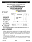
MIT USERS MANUAL Ver. 2.0 Module & Contact Insertion/Extraction Section 1 2.0 TAC (Receiver) Module Installation/Removal P/N 510 130 117 (380 pos. Signal Module), 510 130 121 (220/24 pos. Signal/Coaxial Module)510 130 173 (46 pos. Coaxial or Power Module), 510 130 180 (180/10 pos. Signal/ Coaxial 75 OHM Module) To install a module into the Receiver, place two, #2 Socket Head Cap Screws, .50" in length, in the TAC Receiver Module. Place the Module in the front of the Receiver aligning the locating pins on the module with the appropriate holes in the Receiver Frame, so that the upper and lower module screws touch the mating holes the Receiver Frame (install modules such that the numbers can be read from top to bottom, making them right side up). Using a 5/64 Allen Hex Wrench, tighten the top screw 1 to 2 full revolutions, while lightly applying pressure against the face of the module. Maintain this pressure while tightening the bottom screw 1 to 2 full revolutions. Repeat this sequence, in order, until the module is seated. As the module is being seated, watch to ensure that it does not become cocked at any time as a result of the guide pins not being properly aligned with the receiver or binding of the pins due to one screw being advanced ahead of the other more than 1 to 2 turns. If this should occur, back the screws off until the module is level, and repeat the tightening process. Torque the screw until it is 4 to 5 inch pounds Place the Protective Module Cover on the front of the Receiver with the counter-sunk holes facing upward and verify alignment of the clearance holes with the contacts in the TAC Receiver Module. Using the #2 Flat Head Phillips screws, secure the cap in place until screws are firmly seated. Prior to Module removal, the Protective Module Cover must be removed. To remove, unfasten the two #2 Flat Head Phillips screws and remove the cover. PROTECTIVE MODULE COVER ATTACHES TO FACE OF RECEIVER INSERT TAC MODULE SUCH THAT THE RETAINING PLATE FACES BACK OF RECEIVER SCREENED SIDE UP 4 TAC Module (P/N 510 130 121 shown) in place screened side up. Protective Module Cover has not been secured to the face of the Receiver. P/N: VMMIT100