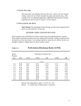
1
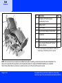
VersaCare® Bed
Quick Reference Guide
Bed
Features
Item
Description
Page
A
Emergency CPR and Emergency
Trendelenburga Control
3
B
Battery Control
4
C
Foot Controls
5
D
Point-of-Care® Caregiver Control Panel
5, 6
E
Control Pod
7, 8,
11
F
IntelliDrive® Transport System (optional)
9
G
Active Integrated Response® Treatment
Surface (optional)
11
E
D
A
B
a. There must be power to the bed, either AC or battery, for
the Emergency Trendelenburg function to operate.
C
F
G
NOTE: In this document, there are references to different bed models. To identify your bed model, look at the serial number label. The
label is on the right side of the weigh frame, under the patient’s shoulder. For example, P3200AXXXX identifies an A model bed.
Also in this document where two versions of a symbol are shown, one or the other will be used on your bed.
Page 2 of 16
For detailed Warning and Caution statements, and operating
instructions, refer to the VersaCare® Bed User Manual (USR119).
For detailed Warning and Caution statements, and operating
instructions, refer to the VersaCare® Bed User Manual (USR119).
Emergency CPR
Emergency Trendelenburg
Safety and Information Indicators
The emergency CPR controls are handles
located under the sleep deck, between the head
and intermediate siderails on both sides of the
bed.
NOTE: The headboard can be used as a CPR
board.
1. Pull and hold the CPR handle. If the bed has
an air mattress, the mattress will go into
Max-Inflate.
The emergency Trendelenburg controls are
handles located under the sleep deck, between
the head and intermediate siderails on both
sides of the bed. The handles used to operate
CPR are also used to operate emergency Trendelenburg.
NOTE: There must be power to the bed, either
AC or battery, for the Emergency Trendelenburg
function to operate.
1. Make sure the bed is plugged into AC power
or the battery is activated.
NOTE: There must be power to the bed, either
AC or battery, for the indicators to operate.
NOTE: A through F models have the Service
is Required indicator only.
2. Hold the CPR handle until the head and
knee section come to a stop in the flat position.
3. Release the CPR handle.
2. Pull and hold the CPR handle.
3. Hold the CPR handle until the head and
knee section come to a stop in the flat position.
4. Continue to hold the CPR handle until you
reach the applicable bed angle.
5. Release the CPR handle.
Disconnected from AC
Power
If the bed is disconnected from
AC power and the battery is
active, the plug indicator flashes.
Service Is Required
When the system determines the bed or air surface operation is not correct, the wrench indicator comes on solid or flashes. Contact your
facility-authorized maintenance person.
Battery Charge is Required
When the battery charge is low, the Battery indicator flashes. Plug the bed into AC power as
soon as possible.
Brake Not Set
If the bed is connected to AC power, and the
brake is not set, the Brake Not Set indicator
(available on some beds) flashes and a continuous alarm comes on. Set the brake to stop the
alarm.
Emergency CPR and
Trendelenburg and
Safety and Information
Indicators
Bed
Page 3 of 16
Bed
Obstacle Detection
and Battery and Foot
Controls
Obstacle Detection
Battery Control
The bed is equipped with an obstacle detection
system that runs along the three open sides of
the base frame. This system detects objects
that are between the upper frame and the base
frame.
If an object is detected, the Bed Not Down indicator on both siderails will flash and you will not
be able to lower the bed.
If an object is detected while the bed sleep deck
is lowering, the bed will stop lowering, and then
raise automatically for 2 seconds. The Bed Not
Down indicator on both siderails will flash.
The Battery control is at the head end of the
bed, on the right side, under the headboard, just
below the power cord.
• The battery stays active for 10 minutes after
the last control is activated.
NOTE: For more information about battery operation with the Bed Exit System or the 30° Head
Angle Alarm, see page 7.
Foot Controls
1. To enable the controls, step down on one of
the Head Down/Up or Bed Down/Up pedals for 1 to 3 seconds.
NOTE: If the battery is fully charged, the battery
indicator will be on. If the battery charge level is
low, the batter indicator will flash. If the battery
indicator is off, the battery may have lost all of
its charge or it may need to be activated. To
charge the battery, plug the bed into an applicable power source.
2. Release the pedal.
3. Step down on the pedal of the applicable
function until the bed is in the correct position.
Activate
Press the Battery control.
• The functions on the caregiver control panel
are available.
• The functions on the control pod are not
available, and the surface indicators will be
off.
Page 4 of 16
Bed Down/Up
Head Down/Up
For detailed Warning and Caution statements, and operating
instructions, refer to the VersaCare® Bed User Manual (USR119).
For detailed Warning and Caution statements, and operating
instructions, refer to the VersaCare® Bed User Manual (USR119).
Enable Control
Caregiver Control Panel Controls
A through F models—the control is
on both the caregiver control panel
and control pod. You must press the
Enable control to use the controls
outside of the caregiver control panel’s blue
section and all controls on the control pod.
G model and newer—the control is on the control pod only. You must press the Enable control
to use the controls in the green sections of the
control pod.
NOTE: The siderail Enable controls do not
enable the Foot pedal controls.
1. Press the Enable control. The indicator
comes on. The Enable control is active for
60 seconds.
Chair
2. During the 60-second period, press the
applicable caregiver control. The 60-second
period starts over each time you press
another control.
1. Set the brake.
2. A through F models, press the Enable
control. G model and newer, go to step 3.
3. Press and hold the
Chair control until the
patient deck goes into
the chair position.
NOTE: Use the reverse
Trendelenburg control for an additional 10° of
forward chair angle.
Bed Flat
A through F models—the Bed Flat control
returns only the sleep deck to the flat position; it
does not change the angle of the bed.
G model and newer—the Bed Flat control
returns the sleep deck and bed to the flat and
level position.
1. A through F models, press the Enable
control. G model and newer, go to step 2.
Enable, Chair, Bed
Flat, and Foot Length
Controls
Bed
2. Press and hold the
Bed Flat control until
all sections are flat and
the system stops.
Foot Extend/Longer and Foot Retract/
Shorter
1. A through F models, press the Enable
control. G model and newer, go to step 2.
2. Press and hold the
applicable Foot
Extend/Longer or
Foot Retract/Shorter
control until the bed is
at the applicable position.
Page 5 of 16
Bed
Boost® Position and
Lockout Controls
Boost® Position System (G model and
Newer
When you activate the Boost® Position System,
the bed will go to a mid-height and flat and level
position. If you continue to hold the control for 5
more seconds, the bed will adjust to 7° Trendelenburg. If an air surface is installed, the surface
will go into Max-Inflate for 30 minutes unless the
Boost® function is deactivated.
NOTE: The Boost® Position is contraindicated
for some patients. Follow your facility's protocols
when you adjust the patient’s position, and refer
to Warnings and Contraindications on page 14.
1. Press and hold the Boost®
Position control:
• Release the control when the
bed is at the flat and level
position.
Or
• If Trendelenburg is not contraindicated for
your patient, hold the control for 5 seconds
longer for the bed to go into the 7° Trendelenburg position.
3. To disengage the Boost® function, press
any of the bed function controls except
these: Boost® System, Bed Up/Down, or
Trendelenburg.
Lockout Control—G Model and Newer
Lockout Controls—A through F Models
Activate
At the same time, press and hold the Enable
control and the applicable Lockout control. An
indicator comes on when a lockout is activated.
The indicator will stay on until the lockout is
deactivated.
All Motors
Head
Bed
Knee
Up/Down Up/Down Up/Down
Deactivate
At the same time, press and hold the Enable
control and the locked out control until the indicator goes off.
Activate
At the same time, press and hold the Lockout
control and the direction control of the applicable function. An indicator and an alarm come on
when a lockout is activated. The indicator will
stay on until the lockout is deactivated.
NOTE: When you activate the lockout for either
the knee up/down or foot longer/shorter control,
both knee up/down and foot longer/shorter
functions will be locked out.
Deactivate
At the same time, press and hold the Lockout
control and the locked out function control until
the indicator goes off.
2. Move the patient to the head of the bed as
necessary.
Page 6 of 16
For detailed Warning and Caution statements, and operating
instructions, refer to the VersaCare® Bed User Manual (USR119).
For detailed Warning and Caution statements, and operating
instructions, refer to the VersaCare® Bed User Manual (USR119).
Bed Exit Alarm System
The Bed Exit controls are on the control pod on
the head-end siderails.
Patient Position
Bed Exiting
Out-of-Bed
Activate
1. Make sure the patient is not on the bed.
2. Zero the scale.
3. Put the patient in the center of the bed and
aligned with the hip locator.
4. Press the Enable control.
5. Press the applicable Bed Exit mode control.
When the system beeps one time and the
indicator stays on solid, the system is
armed.
If the system does not arm, the system will beep
rapidly for a few seconds and the selected mode
indicator will flash. This means: the patient
weighs less than 70 lb (31.8 kg) or more than
500 lb (227 kg); the patient is not in the correct
position; or the system has malfunctioned.
NOTE: If a Bed Exit mode is active and the bed
gets unplugged or the battery activated, the Bed
Exit Alarm System will be inactive. When the
bed is plugged in again, the Bed Exit mode will
activate at the previous setting.
NOTE: When there is a Bed Exit alarm condition, the applicable mode indicator will flash and
you will hear an alarm. To turn off the alarm
sound, you must deactivate the Bed Exit Alarm
System.
Deactivate
At the same time, press and hold the Enable
control and any Bed Exit mode control until the
indicator goes off.
30° Head Angle Alarm (G Model and
Newer)
The 30° Head Angle Alarm control is on the control pod on the head-end siderails.
Activate
1. Raise the head section to the
applicable position above 30°.
2. Press the Enable control.
3. Press the Alarm control. The
indicator comes on and will stay
on until the alarm is deactivated.
NOTE: When the bed operates on
battery power and the alarm is set, if
the head section goes below 30°, an audible
alarm will come on and the alarm indicator will
flash. The display on the control pod will be off.
Turn Off the Alarm
Raise the head section above 30°.
Deactivate
1. Press the Enable control.
2. Press the Alarm control. The indicator will
go off.
Bed Exit and
30° Head Angle Alarm
Bed
Page 7 of 16
Bed
Scale
Scale
Zero the Scale
Weigh the Patient
The scale display and controls are on the control pod on the head-end siderails.
The scale must be zeroed before the patient is
put on the bed.
1. Put all linens, pillows, and equipment on the
bed.
1. A through F models, press the Enable
control. G model and newer, go to step 2.
2. Make sure the patient is not in the bed.
3. Press the Enable control.
NOTE: On some bed models, it is
necessary to press the Enable control to use the scale controls.
1. Make sure the bed is plugged
into electrical power.
2. Put all linens, blankets, pillows, equipment,
and standard items on the bed.
2. Press the Weigh control. The bed shows
the current patient
weight on the display.
4. Press and hold the Zero control
until 00.0 shows on the display
(HOLD will show until 00.0
shows).
NOTE: After you release the Zero
control, the display will flash CALC. Do not
touch the bed until the display shows 0.0.
3. Make sure none of the items on the bed
touch the headboard.
4. Make sure the bed does not touch anything
that could affect the patient weight (headwall, lines such as pendant controls, ventilators, or drainage bags).
5. Make sure the patient is not in the bed.
6. Zero the scale.
Page 8 of 16
For detailed Warning and Caution statements, and operating
instructions, refer to the VersaCare® Bed User Manual (USR119).
For detailed Warning and Caution statements, and operating
instructions, refer to the VersaCare® Bed User Manual (USR119).
IntelliDrive® Transport System
1. Raise all siderails to the up and locked position.
7. Press one or both of the Enable switches on
the transport handles.
tral or Brake, and plug the bed into an applicable power source.
2. Secure all equipment being transported with
the bed (monitors, IV poles, and such).
3. Adjust the bed’s position to make sure your
view is unobstructed.
4. Unplug the bed power cord and, if installed,
the auxiliary outlet power cord from their
power source.
5. Set the Brake/Steer control to Steer
Neutral
8. While you press the Enable switches, push
the transport handles forward or pull them
backward for the applicable direction.
9. To stop, release the handles.
6. Hold one or both transport handles at the
head end of the bed.
NOTE: In case of battery or motor power loss,
press the electronic brake switch to the Off position to permit forward and reverse bed movement
with a deployed, unpowered IntelliDrive® Transport System. The electronic brake switch is on
the right side of the bed, near the foot pedal
controls.
10. If the bed is to be left unattended, set the
brake.
Steer
Brake
11. Stow the handles when the transport is complete.
12. Plug the bed into AC power.
13. To deactivate the IntelliDrive® Transport
System, set the Brake/Steer control to Neu-
On/Off
Switch
IntelliDrive®
Transport
System
Bed
Page 9 of 16
Bed
Troubleshooting
NOTE: If the troubleshooting information shown
below does not fix the problem, contact your
facility-authorized maintenance person.
The Bed Does Not Work
Make sure the bed is plugged into AC power or
the battery is active. For battery information,
refer to “Battery Control” on page 4.
The Service Is Required (Wrench)
Indicator Is On or Flashing
When the system determines the bed or air surface operation is not correct, the wrench indicator comes on solid (bed error) or flashes (air
surface error). Contact your facility-authorized
maintenance person.
The Bed Controls Do Not Work
• Make sure the bed is plugged into AC power
or the battery is active.
• Make sure the lockouts are deactivated. See
page 6 to deactivate them.
NOTE: If all lockout indicators and the service
required indicator are on, contact your facilityauthorized maintenance person.
Page 10 of 16
The Bed Does Not Lower
The Display on the Control Pod Is Off
Make sure of these:
• The bed is plugged into AC power or the battery is active.
• The Bed Down control is not locked out.
• The Bed Not Down indicator is not flashing.
• There is nothing between the upper frame
and the base frame.
• There is nothing between the obstacle detect
sensors on the base frame.
• The obstacle detect covers, located in the
caster covers, are installed correctly.
Make sure the bed is plugged into AC power.
When the bed operates on battery power, the
display will be off.
NOTE: If the bed has the 30° Head Angle Alarm
option and the alarm is set, if the head section
goes below 30°, the audible alarm will come on
and the Head Angle Alarm indicator will flash.
The Foot Controls Do Not Work
Make sure of these:
• The bed is plugged into AC power or the battery is active.
• The lockouts are deactivated.
• You have enabled the foot controls. Refer to
“Foot Controls” on page 4.
The Display on the Control Pod Flashes
when a Weight Is Taken
The maximum weight the scale will show has
been exceeded.
The Head Section Angle Appears to be
much different than the Head Angle Display Shows (G model and newer beds)
Contact your facility-authorized maintenance
person.
The Bed Exit Alarm Does Not Arm and
All Three Mode Indicators Are Flashing
Remove the patient, and zero the Bed Exit system. See “Bed Exit Alarm System” on page 7.
For detailed Warning and Caution statements, and operating
instructions, refer to the VersaCare® Bed User Manual (USR119).
For detailed Warning and Caution statements, and operating
instructions, refer to the VersaCare® Bed User Manual (USR119).
Active Integrated Response®
Treatment Surface
The controls for the Active Integrated Response® Treatment Surface are on the control pod. You
must press the Enable control to use
the surface controls.
Pressure Relief/Normal
Activate
1. Press the Enable control.
2. Press the Pressure
Relief/Normal control.
An indicator will come
on when the mode is
active.
Max-Inflate
Heel Relief
Max-Inflate mode causes the sleep surface to
become very firm. After 30 minutes, if no other
mode is selected, the surface automatically
returns to the Pressure Relief/Normal mode.
NOTE: If the surface is in Max-Inflate mode and
the bed gets unplugged, the surface will stay in
Max-Inflate mode. When the bed is plugged in
again, the surface will go into Pressure Relief/
Normal mode.
Activate
1. Press the Enable control.
For the patient to get heel relief, extend or
retract the bed foot section to align the patient's
heels in the heel relief zone.
NOTE: The Foot Extend/Longer and Retract/
Shorter controls are on the caregiver control
panel.
Activate
1. A through F models,
press the Enable control. G model and
newer, go to step 2.
2. Press the Max-Inflate
control. An indicator
will come on when the
mode is active.
Deactivate
1. Press the Enable control.
2. Press and hold the
Foot Extend/Longer
or Retract/Shorter
control to move the
foot section in or out.
2. Press the Pressure Relief/Normal control.
Pressure Relief/
Normal, Max-Inflate,
and Heel Relief
Air Surface
Page 11 of 16
Air Surface
Turn Assist and Sleep
Mode
Turn Assist
The turn assist bladder inflates and rotates the
patient approximately 20°, which takes about 30
seconds. The system will hold the pressure for
ten seconds. After ten seconds, an alarm
sounds, the turn assist bladder deflates and
returns to Pressure Relief/Normal mode.
NOTE: If a siderail is lowered during
Turn Assist operation, a brief alarm
will sound and the Siderail Not Up
indicator will come on.
Activate
1. Make sure the head angle is below 25°.
2. Make sure the siderails are in the up and
locked position on the side the patient is
turning towards. Turn assist will not start
until the siderails are up.
3. Press the Enable control.
4. Press the Left Turn or
Right Turn control.
The indicator will
come on.
NOTE: If the siderails are
not in the correct position
or the head section is not
below 25°, an indicator will
flash and an alarm will
sound.
Deactivate.
1. Press the Enable control.
2. Press the opposite
Turn control, Pressure Relief/Normal
control, or Max-Inflate
control.
Sleep Mode
Left Turn
Right Turn
The Sleep Mode is used to minimize the frequency of air system adjustments to allow
patients who are sensitive to sleep surface
movement to sleep. The air pressure in the mattress is monitored, but the air pump does not
run unless the air pressure falls below or raises
above a preset level.
Activate
1. Press the Enable control.
Pressure Relief/
Normal
Max-Inflate
2. At the same time, press and hold the Left
Turn and Right Turn controls for 5 seconds.
After 5 seconds, the Left and Right Turn
indicators will come on.
Deactivate
The bed will automatically return to Pressure
Relief/Normal mode after 3 hours or 8 hours (on
some bed models) or if it is necessary to adjust
the mattress pressure.
or
1. Press the Enable control.
2. Press any air system control. The applicable
control indicator will come on.
Page 12 of 16
For detailed Warning and Caution statements, and operating
instructions, refer to the VersaCare® Bed User Manual (USR119).
For detailed Warning and Caution statements, and operating
instructions, refer to the VersaCare® Bed User Manual (USR119).
NOTE: If the troubleshooting information shown
below does not fix the problem, contact your
facility-authorized maintenance person.
The Service Is Required (Wrench)
Indicator Is Flashing
When the system determines the bed or air surface operation is not correct, the wrench indicator comes on solid (bed error) or flashes (air
surface error). Contact your facility-authorized
maintenance person.
The Surface Does Not Inflate or Does
Not Inflate Correctly
Make sure of these:
• The bed is plugged into AC power.
• The Service Is Required indicator is not flashing.
• You press the Enable control before you
press the applicable mattress function.
• The mattress retaining straps at the head and
foot ends of the bed are installed in their
retainers.
Turn Assist Does Not Work
• Make sure of these:
• The bed is plugged into AC power.
• The siderails that the patient is turning toward
are in the up and locked position.
• The head section is below 25°.
• You press the Enable control before you
press the applicable Turn Assist Mode control.
The Surface Mode Indicators are
Flashing
1. Unplug the bed, and wait for 10 seconds.
2. Plug the bed into an applicable power
source.
Retainer
Retaining Strap
Page 13 of 16
Troubleshooting
Air Surface
Warnings and
Contraindications
Evaluate patients for entrapment risk according to facility protocol, and
monitor patients appropriately. Make sure all siderails are fully latched
when in the raised position. Failure to do either of these could cause serious injury or death.
Relative Contraindication for beds with an air surface—use of active
therapy surfaces with patients with unstabilized spinal cord injury could cause
serious injury to the patient.
Beds with the Boost® Position System—do not use the Boost® function if
there are concerns of spinal instability. To do so could cause patient
injury.
We recommend that you do not transport a patient when the bed is in the
Chair or Boost® positions. And, use caution if you transport a patient
when the bed is in the Trendelenburg or Reverse Trendelenburg positions.
IV pole use—the head-end equipment sockets do not move up and down
with the sleep deck. Use applicable precautions with gravity-sensitive
devices such as ventricular drains or lumbar drains before, during, and
after you operate the bed functions. Make sure flow rates on all gravityfed IVs are correct after you adjust the bed height. Failure to correctly
manage patient equipment could cause patient injury.
Page 14 of 16
Make sure the bed is in the low position when the patient is unattended.
This can reduce the possibility of patient falls and the severity of any
resultant injuries.
NOTE: Whenever the bed is not in its low position, the Bed Not Down
indicator will be on.
Bed with an auxiliary outlet—do not plug both power cords into the same
wall receptacle. Plug the power cords into different receptacles on separate circuits. Failure to do so can cause equipment damage or tripping of
facility power breakers. Do not use the accessory receptacle for life support equipment. Plug life support equipment directly into facility power
supply.
Beds with the IntelliDrive® Transport System—if the bed moves forward
or reverse unintentionally, contact your facility-authorized maintenance
person. Failure to do so can cause personal injury or equipment damage.
Beds with the Line Managers—do not use the Line Manager for ventilator
circuits. To do so could cause patient injury.
For detailed Warning and Caution statements, and operating
instructions, refer to the VersaCare® Bed User Manual (USR119).
For detailed Warning and Caution statements, and operating
instructions, refer to the VersaCare® Bed User Manual (USR119).
Patient Weight
500 lb (227 kg) maximum
Safe Working Load (includes patient weight, mattress, IV pumps,
poles, bags, traction equipment, and such)
550 lb (250 kg)
Active Integrated Response® Treatment Surface—Patient Characteristics
500 lb (227 kg)
475 lb (215 kg) for effective pressure redistribution
Width up to 35" (89 cm), and/or a height between 59" and 84" (150 cm
to 213 cm).
Page 15 of 16
Patient
Characteristics
© 2008 by Hill-Rom Services, Inc. ALL RIGHTS RESERVED.
No part of this text shall be reproduced without written permission from Hill-Rom Services, Inc.
Active Integrated Repsonse® is a registered trademark of Hill-Rom Services, Inc.
Boost® is a registered trademark of Hill-Rom Services, Inc.
Hill-Rom® is a registered trademark of Hill-Rom Services, Inc.
IntelliDrive® is a registered trademark of Hill-Rom Services, Inc.
NaviCare® is a registered trademark of Hill-Rom Services, Inc.
Point-of-Care® is a registered trademark of Hill-Rom Services, Inc.
VersaCare® is a registered trademark of Hill-Rom Services, Inc.
DS142 REV 3/April 2008
Rental: 800-638-2546
USA: 800-445-3720
www.hill-rom.com
Canada: 800-267-2337
International: 812-934-8173