1
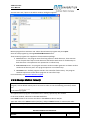
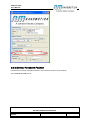
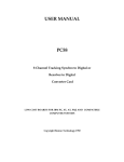
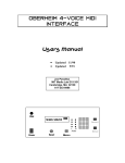
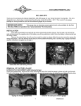
XCD Demo Kit User Manual XCD Controller User Manual 1 REVISION HISTORY .................................................................................................................. 2 2 INTRODUCTION ....................................................................................................................... 2 3 QUICK START .......................................................................................................................... 2 3.1 3.2 3.3 Package Components .............................................................................................................. 2 3.1.1 Motor-drive Assembly ................................................................................................ 3 3.1.2 Communication Box .................................................................................................... 4 3.1.3 Power Adapter ............................................................................................................ 4 3.1.4 Software Installation Disk ........................................................................................... 4 Initial Steps .............................................................................................................................. 4 3.2.1 Hardware Installation.................................................................................................. 4 3.2.2 Software Installation ................................................................................................... 4 Further actions with Presentation Package............................................................................. 7 3.3.1 Monitor Program Execution........................................................................................ 7 3.3.2 Change Motion Program ........................................................................................... 10 3.3.3 Change Motion Velocity ............................................................................................ 11 3.3.4 Monitor Feedback Position ....................................................................................... 12 4 XCD MOTION SCRIPT (XMS) ................................................................................................... 14 4.1 First example of XMS program .............................................................................................. 14 4.2 Numbers ................................................................................................................................ 16 4.2.1 Floating point values ................................................................................................. 16 4.2.2 Literal constants ........................................................................................................ 16 4.2.3 Units .......................................................................................................................... 16 4.3 Variables ................................................................................................................................ 17 4.4 Expressions ............................................................................................................................ 19 4.5 Commands ............................................................................................................................. 19 5 HOST COMMUNICATION ....................................................................................................... 21 5.1 Communication channels ...................................................................................................... 21 5.2 Communication address ........................................................................................................ 22 5.3 Communication protocol....................................................................................................... 22 5.4 Prefixes .................................................................................................................................. 22 5.4.1 UART (RS232) ............................................................................................................ 22 CONTENTS PROPERTY OF Nanomotion Ltd. NO UNAUTHORIZED USE PERMITTED. Document name: XCD Demo kit user manual D/N: XCDC458DMO-00 REV: A Page 1 of 29 XCD Demo Kit User Manual 5.4.2 5.5 5.6 I2C ............................................................................................................................. 23 Command body ..................................................................................................................... 23 5.5.1 General format .......................................................................................................... 23 5.5.2 Command table ......................................................................................................... 24 Reply body ............................................................................................................................. 27 5.6.1 General format .......................................................................................................... 27 5.6.2 Reply body for specific commands ........................................................................... 28 1 Revision History Revision 00/A Date Details 8-Aug-10 Prerelease 2 Introduction XCD Controller is a small but powerful integrated motion controller and drive for Nanomotion piezo-electric motors. The controller provides positioning control of one axis, with configurable motion profile and servo parameters. The controller supports user programming using XMS motion script. With XMS, the customer is able to define complex sequence of motions along with sophisticated calculations and execution control. Prepared XMS program can be stored in the controller flash memory to be executed immediately after power up. 3 Quick Start Use XCD Presentation Package for quick start and experiments with the XCD controller. 3.1 Package Components XCD Presentation Package consists of the following components: 1. Motor-drive assembly 2. Communication box 3. Power adapter 4. Software installation disk CONTENTS PROPERTY OF Nanomotion Ltd. NO UNAUTHORIZED USE PERMITTED. Document name: XCD Demo kit user manual D/N: XCDC458DMO-00 REV: A Page 2 of 29 XCD Demo Kit User Manual 3.1.1 Motor-drive Assembly Components of Motor-drive assembly: XCD controller Connector board EDGE motor + stage + Encoder Encoder XCD Controller EDGE motor Connector board CONTENTS PROPERTY OF Nanomotion Ltd. NO UNAUTHORIZED USE PERMITTED. Document name: XCD Demo kit user manual D/N: XCDC458DMO-00 REV: A Page 3 of 29 XCD Demo Kit User Manual The XCD controller is supplied with application stored in the flash memory. See First example of XMS program for explanation of the stored application. Attention: Stored application begins moving the motor immediately upon connecting the power jack. The Motor-drive assembly is a self-sufficient unit, and only requires power adapter connection to be used for simple demonstration. Connection to computer through Communication box is only required for additional actions, like real-time monitoring or changing the motion program. 3.1.2 Communication Box Communication Box is a passive device providing RS232 connection to the XCD controller. The only Communication Box function is translation of RS232 voltage level to TTL level, which is necessary for the XCD controller. 3.1.3 Power Adapter Power adapter provides 5 V to XCD controller. 3.1.4 Software Installation Disk The disk contains installation files of XSD NanoCommander and several examples of motion programs. 3.2 Initial Steps 3.2.1 Hardware Installation 3.2.1.1 Minimal Installation For minimal installation, use the Motor-drive assembly and connect power adapter to power jack. The application stored in XCD controller begins moving the motor (see Details of Motion Program). 3.2.1.2 Connection to a Computer Connect the Communication box to the Connector board using supplied cable Connect Communication box to computer’s COM port connector using standard RS232 cable If the computer doesn’t have COM port, use USB-COM adapter instead of standard RS232 cable 3.2.2 Software Installation Insert the installation disk into the computer’s CD drive. Installation should start automatically. CONTENTS PROPERTY OF Nanomotion Ltd. NO UNAUTHORIZED USE PERMITTED. Document name: XCD Demo kit user manual D/N: XCDC458DMO-00 REV: A Page 4 of 29 XCD Demo Kit User Manual If auto-start doesn’t work (e.g., disabled by computer’s security settings), start manually SETUP.EXE on the installation disk. If the following dialog appears, press Install: Installation creates group Nanomotion in the Start/Programs menu, and also creates directory XCD NanoCommander on the desktop that contains NanoCommander shortcut and examples of motion programs: In the end of the installation, XCD NanoCommander starts automatically. If message appears reporting communication problem, press Ok: Normally, this or similar message appears only during the first connection. If connection with the controller is not established, the NanoCommander screen looks as follows: CONTENTS PROPERTY OF Nanomotion Ltd. NO UNAUTHORIZED USE PERMITTED. Document name: XCD Demo kit user manual D/N: XCDC458DMO-00 REV: A Page 5 of 29 XCD Demo Kit User Manual Select correct communication port from the Port drop-down list to start communication. If USB-COM adapter is used, the corresponding COM appears in the drop-down list only when the adapter is connected to computer’s USB port. Once communication is established, NanoCommander displays controller data in the Info CONTENTS PROPERTY OF Nanomotion Ltd. NO UNAUTHORIZED USE PERMITTED. Document name: XCD Demo kit user manual D/N: XCDC458DMO-00 REV: A Page 6 of 29 XCD Demo Kit User Manual box: 3.3 Further actions with Presentation Package 3.3.1 Monitor Program Execution On the main NanoCommander window, big button in the Motion Program pane reads either Download & Execute if motion program is idle, or Stop if the program runs: CONTENTS PROPERTY OF Nanomotion Ltd. NO UNAUTHORIZED USE PERMITTED. Document name: XCD Demo kit user manual D/N: XCDC458DMO-00 REV: A Page 7 of 29 XCD Demo Kit User Manual If motion program runs, Line indicator displays number of the currently executed line. Press Edit button: CONTENTS PROPERTY OF Nanomotion Ltd. NO UNAUTHORIZED USE PERMITTED. Document name: XCD Demo kit user manual D/N: XCDC458DMO-00 REV: A Page 8 of 29 XCD Demo Kit User Manual The NanoCommander opens Editor window. The Editor highlights currently executed line. CONTENTS PROPERTY OF Nanomotion Ltd. NO UNAUTHORIZED USE PERMITTED. Document name: XCD Demo kit user manual D/N: XCDC458DMO-00 REV: A Page 9 of 29 XCD Demo Kit User Manual If necessary, extend Editor window by dragging the bottom-right grip: 3.3.2 Change Motion Program If current motion program runs, stop it by pressing Stop button in the Editor window (or in the main window): The button text changes to Download & Execute, indicating the program is idle. CONTENTS PROPERTY OF Nanomotion Ltd. NO UNAUTHORIZED USE PERMITTED. Document name: XCD Demo kit user manual D/N: XCDC458DMO-00 REV: A Page 10 of 29 XCD Demo Kit User Manual Activate menu File / Open in the Editor window. Dialog box appears: Motion program have extension TXT. Select desired motion program and press Open. Start the new program by pressing Download & Execute button. Three motion programs are supplied in the Presentation package: SCRIPTPOS.TXT – the program starts from long motion in both directions, then executes series of equal short steps in both directions and finishes with series of variable steps in both directions. The operations are repeated in an infinite loop. RANDOMPOINTS.TXT – the program activates random number generator to obtain random coordinate of the next point. The program operates in an infinite loop. COMBINED.TXT – default program stored in the controller flash memory. The program combines operations of two above programs in one infinite loop. For more details, see Details of Motion Program. 3.3.3 Change Motion Velocity Attention: The last versions of COMBINED.TXT and SCRIPTPOS.TXT assign motor velocity in the program, so that default velocity VEL is not used. In order to use the following procedure, delete line VEL=10+V0*35 in the motion program. All supplied motion program use default motion velocity specified by VEL variable. In the main window, select VEL in the Var combo box. Press Read button to see current VEL value in the Value text box in mm/sec. Type new value in the Value text box (mm/sec), and press Write button to activate new value. Attention: don’t specify more than 200 mm/sec, as the motor is not able to move faster. CONTENTS PROPERTY OF Nanomotion Ltd. NO UNAUTHORIZED USE PERMITTED. Document name: XCD Demo kit user manual D/N: XCDC458DMO-00 REV: A Page 11 of 29 XCD Demo Kit User Manual 3.3.4 Monitor Feedback Position Continuous monitoring of feedback position is provided in the Servo Loop window. Press Tune Servo Loop button: CONTENTS PROPERTY OF Nanomotion Ltd. NO UNAUTHORIZED USE PERMITTED. Document name: XCD Demo kit user manual D/N: XCDC458DMO-00 REV: A Page 12 of 29 XCD Demo Kit User Manual The Servo Loop window opens. Watch feedback position (mm) in the Current Position window. CONTENTS PROPERTY OF Nanomotion Ltd. NO UNAUTHORIZED USE PERMITTED. Document name: XCD Demo kit user manual D/N: XCDC458DMO-00 REV: A Page 13 of 29 XCD Demo Kit User Manual Attention: avoid changing servo loop parameters, as improper values may deteriorate motor performance, and even make servo loop unstable. Proper values of servo parameters are already stored in the controller flash memory, and should not be changed. If, however, some parameter has been unintentionally changed, the simplest way of returning the controller to default state is restarting the controller with power cycling. 4 XCD Motion Script (XMS) 4.1 First example of XMS program The following example (program COMBINED.XMS) executes a set of motions. Each motion is positioning to a point in range 0 – 20 mm. The program demonstrates usage of the following language elements: User variables (V0, V1, V10) System variables (VEL, RPOS) Literal constants in integer, real, and hexadecimal formats Expressions containing variables, constants, arithmetic and logical operations Commands (move, home, delay) Execution control commands (while, for, end) The following table provides step-by-step explanation of the motion program COMBINED.XMS. V10=999 Seed of random number generator assigned to variable V10. while 1 WHILE loop executes forever, as condition expression is always non-zero. home 30 Homing, scheme 30 to the left hard stop for V1=0 to 5 FOR loop executes 6 times, loop variable V1 changes from 0 to 5. // Force-back move Comment. for V0=0 to 5 Inner FOR loop executes 6 times, loop variable V0 changes from 0 to 5. VEL=10+V0*35 Set required motion velocity. Velocity starts from 10 mm/sec, then grows to 45, 80, 115, 150, and finally to 185 mm/sec. move 5 Move to absolute position 5 mm. move 15 Move to absolute position 15 mm. end End of inner FOR loop. move 0 Move to absolute position 0 mm. CONTENTS PROPERTY OF Nanomotion Ltd. NO UNAUTHORIZED USE PERMITTED. Document name: XCD Demo kit user manual D/N: XCDC458DMO-00 REV: A Page 14 of 29 XCD Demo Kit User Manual // Incremental move forward for V0=0 to 3 Comment. Inner FOR loop executes 4 times, loop variable V1 changes from 0 to 5. move RPOS+4 Move to relative position, increment 4 mm. delay 100 Delay 100 milliseconds. end End of inner FOR loop. // Incremental move backward for V0=0 to 3 Comment. Inner FOR loop executes 4 times, loop variable V1 changes from 0 to 5. move RPOS-4 Move to relative position, increment -4 mm. delay 100 Delay 100 milliseconds. end End of inner FOR loop. // Variable step forward for V0=1 to 8 Comment. Inner FOR loop executes 8 times, loop variable V1 changes from 1 to 8. move RPOS+0.5*V0 Move to relative position, increments 0.5, 1, 1.5, etc. delay 100 Delay 100 milliseconds. end End of inner FOR loop. // Variable step backward for V0=1 to 8 Comment. Inner FOR loop executes 8 times, loop variable V1 changes from 1 to 8. move RPOS-0.5*V0 Move to relative position, increments -0.5, -1, -1.5, etc. delay 100 Delay 100 milliseconds. end End of inner FOR loop. end End of outer FOR loop. // Positioning to random points for V1=0 to 200 Comment. // random number generator (11 bits) V10=V10*993+1 V10=V10&0x07FF Comment. FOR loop executes 201 times, loop variable V1 changes from 0 to 200. Generate random number equally distributed in the range from 0 to 2048. Symbol & designates logical AND, literal 0x07FF is hexadecimal constant equal to decimal 2047. CONTENTS PROPERTY OF Nanomotion Ltd. NO UNAUTHORIZED USE PERMITTED. Document name: XCD Demo kit user manual D/N: XCDC458DMO-00 REV: A Page 15 of 29 XCD Demo Kit User Manual // V10 is random number in range from 0 to 2048 move 18*V10/2048 delay 100 Comment. Move to random absolute position in the range from 0 to 18 mm. Delay 100 milliseconds. end End of FOR loop. end End of WHILE loop. 4.2 Numbers 4.2.1 Floating point values All numbers in XMS program are floating point values complying with IEEE 754 definition of single precision arithmetic. Range of values is from approximately -3.4*1038 to +3.4*1038. 4.2.2 Literal constants In XMS program, literal constant can appear in different formats. Format of a literal constant doesn’t affect its internal presentation; the controller converts each constant to floating point number before using it in calculations. The following table summarizes available formats: Format Examples Integer 1, 20, -1078 Real 0.1, 20.35, 0.000009 Scientific 1e-5, 2.3e10 Hexadecimal 0x07FF, 0x1E23 4.2.3 Units The controller supports predefined measuring units for physical values. For example, position or distance in XMS program is always specified in millimeters. The following table summarizes usage of measuring units: Value Example of variables Measuring unit Position, distance POS, RPOS, FPOS, TPOS Millimeter (mm) Velocity VEL, RVEL, FVEL Millimeter per second (mm/sec) Acceleration ACC Millimeter per second per second (mm/sec2) Time interval delay parameter Millisecond (msec) CONTENTS PROPERTY OF Nanomotion Ltd. NO UNAUTHORIZED USE PERMITTED. Document name: XCD Demo kit user manual D/N: XCDC458DMO-00 REV: A Page 16 of 29 XCD Demo Kit User Manual Scaled values AIN0, AOUT1, DOUT Percents of maximum (%) 4.3 Variables All variable names in XMS program are predefined; the customer is not allowed to define a new variable name. XMS variables are subdivided into two classes: System variables; each system variable has predefined meaning, like VEL – required motion velocity FPOS – feedback position User variables with predefined names V0, V1, V2 … V19. A user variable has no predefined meaning, and can store any number required in a program. The following table summarizes XMS variables in categorical order: ID Name Comments Required motion parameters 0 POS Position 1 VEL Velocity 2 ACC Acceleration 4 KDEC Kill deceleration – used in fault conditions; e.g., if limit switch was activated. Instant reference motion variables 5 TPOS Target position 6 RPOS Reference position 7 RVEL Reference velocity 8 RACC Reference acceleration Instant feedback motion variables 9 FPOS Feedback position 10 FVEL Feedback velocity 11 FACC Feedback acceleration 12 PE Position error Servo loop and drive configuration 13 KP Position loop gain 14 KV Velocity loop gain 16 LI Velocity loop integrator limit CONTENTS PROPERTY OF Nanomotion Ltd. NO UNAUTHORIZED USE PERMITTED. Document name: XCD Demo kit user manual D/N: XCDC458DMO-00 REV: A Page 17 of 29 XCD Demo Kit User Manual 17 BQA1 Bi-Quad filter parameters 18 BQA2 19 BQB0 20 BQB1 21 BQB2 22 ENR Encoder resolution (millimeters per one encoder count ) 23 MFREQ Motor frequency (PWM frequency) 24 SPRD Servo loop sampling period (milliseconds) 25 DMODE Drive mode, reads the following values: 1 – EDGE drive, low resolution 2 – EDGE drive, high resolution 11 – HR drive, low resolution 12 – HR drive, high resolution 26 MFREQ1 Alternative motor frequency. If MFREQ1 value is different from MFREQ value, the motor frequency depends on PWM duty cycle. At zero PWM, the frequency is MFREQ; at 100% PWM, the frequency is MFREQ1; in between the frequency changes linearly. See explanation in <>. 27 PWMZERO PWM characteristic. See explanation in <>. 28 PWMMIN 29 PWMMAX 40 DZMIN Dead zone min (Nanomotion algorithm) 41 DZMAX Dead zone max (Nanomotion algorithm) 42 ZFF Zero feed forward (Nanomotion algorithm) 43 FRP Friction in positive direction 44 FRN Friction in negative direction 45 DOUT Instant drive output (% of maximal output) 39 DOL Drive output limit (% of maximal output) 47 SLP Software limit positive 48 SLN Software limit negative 49 PEL Position error limit 50 TEL Temperature Limit Safety CONTENTS PROPERTY OF Nanomotion Ltd. NO UNAUTHORIZED USE PERMITTED. Document name: XCD Demo kit user manual D/N: XCDC458DMO-00 REV: A Page 18 of 29 XCD Demo Kit User Manual 51 MTL Motion Time limit Analog inputs/outputs 30 AIN0 Analog input 0 (%) 31 AIN1 Analog input 1 (%) 34 AOUT0 Analog output 0 (%) 35 AOUT1 Analog output 1 (%) User variables 1000 1019 V0 – V19 User variables Flags (accept values 0 or 1 only) 2000 SC_IDO Inverse drive output 2001 SC_IEN Inverse feedback direction 2002 SC_EBQ Enable bi-quad filter 2007 IN_0 Digital input 0 2008 IN_1 Digital input 1 2011 OUT_0 Digital output 0 2012 OUT_1 Digital output 1 4.4 Expressions Expression is a formula calculating a numerical value. In its simplest form, expression consists of a single variable or literal constant. General expression may include the following elements: Variables like VEL, V10, IN_0 Literal constants like 10, -0.0001, 0x0FFF Parenthesis: ( and ) Arithmetical operations: +, -, *, / Compare operations: = (equal), <> (non-equal) , < (less), <= (less or equal), > (greater), >= (greater or equal) Logical operations: & (and), | (or), ^ (exclusive or) 4.5 Commands Command is a main building block of a motion program. The following table includes syntax definition statements, using the following formats: CONTENTS PROPERTY OF Nanomotion Ltd. NO UNAUTHORIZED USE PERMITTED. Document name: XCD Demo kit user manual D/N: XCDC458DMO-00 REV: A Page 19 of 29 XCD Demo Kit User Manual bold Bold text specifies literal terms, which appear in the script exactly as specified. italic Italic text specifies syntax units explained in the right column. Any syntax unit belongs to one of the following groups: variable – one of the variable names expression – arithmetical/logical expression commands – any sequence of the controller commands For example, in definition “move absolute_position”, absolute_position is an expression that generates variety of possible lines, for example: move 750 move TPOS+225 move V19*300+600 Definition “variable = expression” generates assignment commands, for example: V9 = V9 +1 VEL = V10*10 Command syntax Comments variable = expression Assignment. Right-part expression is calculated and its result is assigned to variable in the left. move absolute_position Move to absolute position. absolute_position is an expression that defines new target position. kill Kill motion. Current motion is terminated, and the controller provides deceleration using KDEC parameter. home home_scheme, position, velocity1, velocity2 Homing. home_scheme selects one of the standard homing sequences. position (optional) is an expression that sets position value in the home point. If omitted, zero is used. velocity1 and velocity2 (optional) are expressions that define velocities at different homing stages. If omitted, VEL value is used. openloop command Open loop. The controller switches to open-loop operation; command is an expression that defines drive output CONTENTS PROPERTY OF Nanomotion Ltd. NO UNAUTHORIZED USE PERMITTED. Document name: XCD Demo kit user manual D/N: XCDC458DMO-00 REV: A Page 20 of 29 XCD Demo Kit User Manual Command syntax Comments value. velocityloop velocity Velocity loop. The controller switches to velocity-loop operation; velocity is an expression that defines target velocity. setposition position Set position. position is an expression that defines new position in the current point. The command effectively defines new axis origin. delay time Delay. time is an expression that defines delay time in milliseconds. if expression then Conditional statement. commands1 else If the expression yields non-zero value, commands1 are executed, else commands2 are executed. commands2 The <else command2> close can be omitted. end for variable = initial to final step step For loop. commands The commands within a loop are repeated specified number of times. The loop header defines loop variable (one of user variables V0-V19), initial value of the loop variable, final value of the loop variable, and step. Loop variable is incremented by step on each repetition. end while expression While loop. commands The commands within a loop are repeated while expression yields non-zero value. end 5 Host Communication 5.1 Communication channels Communication with the host computer is provided through the following physical channels: UART (RS232) 115000 baud I2C up to 400 kHz SPI up to 10 MHz CONTENTS PROPERTY OF Nanomotion Ltd. NO UNAUTHORIZED USE PERMITTED. Document name: XCD Demo kit user manual D/N: XCDC458DMO-00 REV: A Page 21 of 29 XCD Demo Kit User Manual 5.2 Communication address Each controller stores its communication address, which is a number within range from 0 to 254. Factory default is zero. The customer can change controller’s address with command Set address (16). Then newly defined address can be stored in the controller flash memory with command Save (13) to be retrieved at each power-up. Each host command includes destination address. If destination address is in range from 1 to 254, the controller accepts and responds the command only if its address matches the command destination address. Zero destination address defines broadcasting, i.e. any connected controller accepts and responds the command. 5.3 Communication protocol The controller is a communication client and performs passive role. Other side (customer processor or PC) is a communication host and performs active role. Communication executes in a ping-pong manner. Each communication session includes two events: Host initiates communication by sending a command. Controller sends reply; in many cases, the reply is simply a prompt reporting if the command was accepted or rejected. The host commands and the controller replies are similar in all supported communication channels. Each host command consists of the following parts: Command prefix Command prefix depends on the communication channel. Command prefix is the same for all commands. Command body Command body doesn’t depend on the communication channel. Command body is specific for each command. Controller reply has similar parts: Reply prefix Reply prefix depends on the communication channel. Reply prefix is the same for all commands. Reply body Reply body doesn’t depend on the communication channel. Reply body is specific for each command. 5.4 Prefixes 5.4.1 UART (RS232) Command prefix and reply prefix are identical and consist of 4 bytes: Byte offset Size in bytes Content 0 1 Constant 0xE4 (228). CONTENTS PROPERTY OF Nanomotion Ltd. NO UNAUTHORIZED USE PERMITTED. Document name: XCD Demo kit user manual D/N: XCDC458DMO-00 REV: A Page 22 of 29 XCD Demo Kit User Manual 1 1 Constant 0xA5 (165). 2 1 Destination address. 3 1 Length of command/reply body in bytes. 5.4.2 I2C Command prefix consists of 2 bytes: Byte offset Size in bytes Content 0 1 Destination address (write address). 1 1 Length of command body in bytes. Reply prefix consists of 2 bytes: Byte offset Size in bytes Content 0 1 Destination address plus one (read address). This byte is sent by the host. 1 1 Length of reply body in bytes. This byte is sent by the controller. 5.5 Command body 5.5.1 General format Command body is a sequence of bytes in the following order: Byte offset Byte size Content 0 1 Command code. 1 Up to 49 Parameters. If a command requires no parameters, the whole body includes only one byte – command code. In most commands, the command code is followed by parameters. Each parameter occupies one or several bytes. No delimiting bytes are added between the command code and parameters or between the parameters. Each parameter is a numerical value. Each command requires specific format for each of its parameters. All formats are binary, least significant byte appears first. The following formats are used: Format Number of bytes Range Int8 1 -128 to +127 CONTENTS PROPERTY OF Nanomotion Ltd. NO UNAUTHORIZED USE PERMITTED. Document name: XCD Demo kit user manual D/N: XCDC458DMO-00 REV: A Page 23 of 29 XCD Demo Kit User Manual Int16 2 -32768 to +32767 Real 4 -3.4*1038 to +3.4*1038 approximately (complying with IEEE 754) ID 2 0 to 65535 Some commands require a parameter that specifies a controller variable. The variable is referenced by its numerical ID. See Variables table for variable ID’s. 5.5.2 Command table Command Code Parameters Format (size in bytes) Comments Move 1 Real (4) Move to absolute position. position position defines new target position in mm. Assign Home 3 4 variable ID (2) value Real (4) Assignment. The value is assigned to the variable. scheme Int8 (1) Homing. origin (opt) Real (4) velocity1 (opt) Real (4) scheme selects one of the standard homing sequences. velocity2 (opt) Real (4) origin defines position in the home point. If omitted, zero is taken. velocity1 defines first stage velocity. If omitted, VEL value is taken. velocity2 defines second stage velocity. If omitted, one fourth of velocity1 is taken. Velocity loop 6 Open loop 7 velocity Real (4) Execute velocity loop control. Parameter velocity defines required velocity in mm/sec. command Real (4) Execute open loop control. Parameter command defines command value in percents, from -100 to +100. Set position 11 position Real (4) Set position. Parameter position defines new position in the current point. The command effectively defines new axis origin. CONTENTS PROPERTY OF Nanomotion Ltd. NO UNAUTHORIZED USE PERMITTED. Document name: XCD Demo kit user manual D/N: XCDC458DMO-00 REV: A Page 24 of 29 XCD Demo Kit User Manual Command Code Parameters Format (size in bytes) Comments Set frequency 12 Real (4) Set frequency. freq freq1 (opt) Parameters freq and freq1 define motor (PWM) frequency in Hz. If omitted, freq1 is taken the same as freq. If freq1 ≠ freq, the motor frequency depends on PWM duty cycle. At zero PWM, the frequency is freq; at 100% PWM, the frequency is freq1; in between the frequency changes linearly. See explanation in <>. Save parameters 13 addr Int8 (1) Save parameter values into flash memory. 90 (0x5A) Int8 (1) At the next start-up, the controller reads the parameters from the flash and starts with the stored parameters instead of default values. The parameters are required to prevent unintentional use of the command. addr specifies communication address of the controller. The second parameter is constant 90 (0x5A). Set address 16 addr Int8 (1) Change communication address. 90 (0x5A) Int8 (1) newaddr Int8 (1) First two parameters are required to prevent unintentional use of the command. addr specifies current communication address of the controller. The second parameter is constant 90 (0x5A). newaddr specifies new communication address of the controller. Read version 19 Read version. The command requests information about controller firmware. See format of controller reply below. CONTENTS PROPERTY OF Nanomotion Ltd. NO UNAUTHORIZED USE PERMITTED. Document name: XCD Demo kit user manual D/N: XCDC458DMO-00 REV: A Page 25 of 29 XCD Demo Kit User Manual Command Code Parameters Format (size in bytes) Comments Monitor 20 channel Int8 (1) Monitor variable. variable ID (2) scale Real (4) Being commanded, the controller in each cycle converts the variable using the scale and passes it to analog output. channel defines analog output to use: 0 – AOUT0, 1 – AOUT1. variable specifies variable to monitor. scale defines a conversion factor. Monitor address 21 channel Int8 (1) Monitor variable. address Int16 (2) scale Real (4) Being commanded, the controller in each cycle converts the specified RAM address using the scale and passes it to analog output. channel defines analog output to use: 0 – AOUT0, 1 – AOUT1. address specifies variable to monitor. scale defines a conversion factor. Set mode 22 mode Int8 (1) Set drive mode. mode specifies one of the following values: 1 – EDGE drive, low resolution 2 – EDGE drive, high resolution 11 – HR drive, low resolution 12 – HR drive, high resolution Report Set PWM 26 38 var1 ID (2) Report variable values. var2 (opt) ID (2) … … var10 (opt) ID (2) The command requests current variable values. From 1 to 10 variables can be requested in one command. See format of controller reply below. zero Real (4) Set PWM characteristic. min Real (4) zero, min, and max define the characteristic. max Real (4) See <> for more details. CONTENTS PROPERTY OF Nanomotion Ltd. NO UNAUTHORIZED USE PERMITTED. Document name: XCD Demo kit user manual D/N: XCDC458DMO-00 REV: A Page 26 of 29 XCD Demo Kit User Manual Command Code Parameters Format (size in bytes) Comments Configure safety 39 addr Int8 (1) Configure safety signals. 90 (0x5A) Int8 (1) config Int8 (1) First two parameters are required to prevent unintentional use of the command. addr specifies communication address of the controller. The second parameter is constant 90 (0x5A). config is a bit mask that defines signal polarity: Bit 0 – Negative Limit Bit 1 – Positive Limit Bit 2 – Emergency Stop Zero value of a bit defines active-high polarity (fault occurs if the signal has high level); value one defines active-low polarity. By default, all safety signals are configured active-low. Disable safety 40 addr Int8 (1) Configure safety signals. 90 (0x5A) Int8 (1) disable Int8 (1) First two parameters are required to prevent unintentional use of the command. addr specifies communication address of the controller. The second parameter is constant 90 (0x5A). disable is a bit mask: Bit 0 – Negative Limit Bit 1 – Positive Limit Bit 2 – Emergency Stop Bit 3 – Motor Not Connected Zero value of a bit enables safety signal; value one disables safety signal. By default, all safety signals are enabled. 5.6 Reply body 5.6.1 General format Reply body is a sequence of bytes in the following order: CONTENTS PROPERTY OF Nanomotion Ltd. NO UNAUTHORIZED USE PERMITTED. Document name: XCD Demo kit user manual D/N: XCDC458DMO-00 REV: A Page 27 of 29 XCD Demo Kit User Manual Byte offset Byte size Content 0 1 Command code – copied from replied command. 1 1 Result: 1 – Command accepted. 2 – Command rejected. 2 Up to 48 Total 2 ÷ 50 Extension. For most commands, the controller sends back only two bytes with no extension. 5.6.2 Reply body for specific commands 5.6.2.1 Read version (19) Byte offset Byte size Content 0 1 Command code – copied from replied command. 1 1 Result: 1 – Command accepted. 2 – Command rejected. 2 4 Version. 6 4 Serial number. 10 2 Application code. Total 12 5.6.2.2 Report (26) Byte offset Byte size Content 0 1 Command code – copied from replied command. 1 1 Result: 1 – Command accepted. 2 – Command rejected. 2 4 Variable 1 in Real format. 6 4 Variable 2 in Real format (if requested). … … … 38 4 Variable 10 in Real format (if requested). CONTENTS PROPERTY OF Nanomotion Ltd. NO UNAUTHORIZED USE PERMITTED. Document name: XCD Demo kit user manual D/N: XCDC458DMO-00 REV: A Page 28 of 29 XCD Demo Kit User Manual Total 6 ÷ 42 CONTENTS PROPERTY OF Nanomotion Ltd. NO UNAUTHORIZED USE PERMITTED. Document name: XCD Demo kit user manual D/N: XCDC458DMO-00 REV: A Page 29 of 29