1
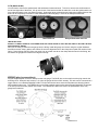
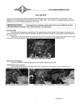
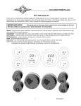
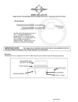
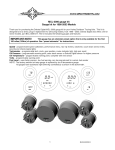
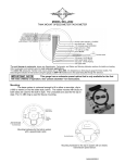
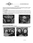
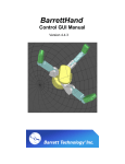
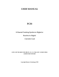
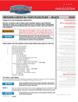
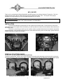
MCL-36K-SPD
Thank you for purchasing the Dakota Digital MCL-36K-SPD gauge for your Harley Davidson Touring bike. This kit is
designed to be a direct, plug in replacement for all touring models from 2004 – 2011. This is part of a six gauge
package for touring models so you can add additional gauges as you choose.
IMPORTANT NOTE!
This gauge has an odometer preset option that is only available for the first
100 miles (160km) of operation. See ‘‘preset odometer’’ for instructions.
INSTALLATION
First read and familiarize yourself with all of the components and this manual. The first step is to remove the
seat and disconnect the negative side of the battery, as with any electronic install. Once the battery is disconnected you
are ready to start.
Remove the outer fairing; this will vary from model to model, so please follow the service manual to expose the
wiring and gauges. Don’t be alarmed by the amount of wires behind the fairing, this is a direct plug in gauge and these
detailed instructions will guide you through it.
Street Glide with outer fairing removed
Road Glide with outer fairing removed
REMOVAL OF FACTORY GAUGE
ULTRA FLHT & FLHX (STREET GLIDE batwing fairings)
Unplug the speedometer. Remove the screws securing the clamp that holds the gauge in place and pull it out through
the front of the fairing. Save the screws, gasket, and clamp to be reused when you install the new Dakota Digital gauge.
Unplug the factory speedometer
Unscrew the clamp and remove gauge
1
MAN#650333:A
FLTR (ROAD GLIDE)
You will need to remove the speedometer and tachometer instrument bezel. To do this, remove two small screws on
the left and right side of the bezel. Lift up on the back of the bezel and slide the tab that is under the ignition switch out
from under the switch cover (see Photo A below). Unplug the gauge connections and unplug the indicator lights so the
bezel can be completely removed for easier installation of the new gauge. Remove the clamp that holds the
speedometer to the bezel and remove the gauge and gasket.
Photo A
Bezel removed
Gauges/Grommets removed
IMPORTANT NOTE!
SAVE ALL CLAMPS, GASKETS, and SCREWS FROM THE STEPS ABOVE AS THEY WILL BE USED TO SECURE THE NEW
DAKOTA DIGITAL GAUGE
Next you are ready to install the new gauge into the fairing. Install the gauge and secure using the original hardware
that was removed: clamp, gasket, and screws. Be sure the alignment tab on the clamp lines up with the notches in the
fairing. Some fairings may only have one notch, line up at least one tab on the clamp with the notch in the fairing, this
will ensure the gauges are centered and aligned correctly.
WIRING (plug in connections)
Plug the original speed connector directly into the new gauge. The BLUE wire on the small, two-wire plug controls the
dimming circuit. When this wire receives +12 volts, the gauge will dim to 50% intensity. This wire can be connected to a
toggle switch, or to a Dakota Digital MCL-36K-TCH (the tachometer has a sensor that activates the dimming feature
when ambient light is low). The GREEN wire can provide a switch signal to allow other Dakota Digital MCL-3K gauges
to be set up from the factory switch on the dash. The GREEN wire will not be used if the speedometer is the only
gauge being replaced.
2
MAN#650333:A
FUNCTION SWITCH
The factory speedometer push button switch is used as the main function switch. The function switch allows
access to all of the mileage and performance information. Pressing and releasing the function switch toggles through
the different displays. Pressing and holding the switch for about 2 seconds will reset the current display. The display
sequence for the speedometer is as follows:
SPEED MENU
000000
odometer mileage
A
000.0
trip meter mileage A
000.0
trip meter mileage B
B
S 0000
miles since last service (if programmed)
++++++
speedometer will show km/h (or MPH if metric)
PERFORMANCE MENU(on speedometer when enabled)
HI 00
high speed recall
60 00.0
0-60 mph time (0- 00.0 0-100kph)
25 00.0
quarter mile time
25 00
quarter mile speed
T 000F
cylinder head temp from ECM (run switch must be on)
The 0-60 and ¼ mile timers are zeroed by pressing and holding the switch while that timer is displayed. The timer will not
restart until the speed reaches zero and you start driving again.
GAUGE SETUP AND CALIBRATION
The function switch, discussed above, is used to enter setup mode for all of the gauges. If you are only
installing one or a couple Dakota Digital MCL-3K gauges, then setup may seem a little strange since they are designed
to work as a set. The first step in the setup procedure is to select which gauge you are going to adjust. Each gauge
will either show a number or a label. If the gauge is showing a label then that gauge will be selected to enter setup. All
of the other gauges will exit setup and allow the selected gauge to be changed. To get into setup, press and hold the
function switch while turning the key on. Press and release the switch to advance through the menus below, when on
the desired option press and hold the switch to select setup for that particular gauge/function.
Volt
Speed
Tach
Oil PSI
Oil Temp Fuel
st
1
- 1 CL
- 1 - 1 - 1 - 1 nd
2
SPd
- 2 - 2 - 2 - 2 - 2 rd
3
- 3 tCH
- 3 - 3 - 3 - 3 th
4
- 4 - 4 PSI
- 4 - 4 - 4 th
5
- 5 - 5 - 5 F or C
- 5 - 5 th
6
- 6 - 6 - 6 - 6 FUL
- 6 th
7
- 7 - 7 - 7 - 7 - 7 uLt
th
8
- 8 - 8 - 8 - 8 - 8 - 8 FACTORY DEFAULT SETTINGS FOR SETUP MENUS
Below is a list of factory gauge settings and what can be adjusted in the setup menus. You can calibrate and
adjust speedometer as often as you wish, however it should only need to be set once. The calibration will be correct for
a stock bike, but the speed can be adjusted to compensate for a change in tire size, pulley size or transmission
gearing.
Speedometer calibration 1.00
Unit
Service meter
Performance Menu
Fuel selection
MPH
OFF
ON
OFF
3
MAN#650333:A
SPEEDOMETER SETUP
Main Menu
Sub Menu
SPd
dIAG
AdJvSt
vnIt
S SEt
PErF
FvEL
-odoMK
Description
Read diagnostic codes from engine or security modules.
select adjust calibrate speed
select speed unit (MPH or km/h, default MPH)
miles to service setting (default off)
enable/disable performance readings (default on)
select fuel sender type (default off)
one-time odometer preset (only shown while odometer has less than 100 miles)
Press and hold the switch while turning the key on. Release the switch. The speedometer will show “-1-”. Press
and release the switch so that “SPd” is displayed. Press and hold the switch for about 3 seconds until “-” is displayed.
Release the switch. The MPH display will show “SEt” and the odometer display will show “dIAG”. Press and release the
switch to move through the different speedometer setup menus; press and hold the switch to select a menu option.
dIAG Diagnostics mode for checking/clearing trouble codes
•
•
•
•
Press and release the switch until “dIAG” is displayed, then press and hold the switch until “ - “ is displayed.
Release the switch. The display will show “ENGINE”, “SECvRE”, ”ABS”, or “DoNE”.
Press and release the switch to change the selection, press and hold the switch until “ - “ is displayed to begin reading the stored
codes for the particular system.
Release the switch. The display will show the current codes, “none”, or “no rsp”. Press and release the switch to move to the
next stored code. After all codes are displayed the module part number will be scrolled across the screen. To clear codes, press
and hold the switch when “end” is displayed. Consult a service manual for trouble code descriptions.
AdJ
AdJuSt Speed Calibration
The speedometer is calibrated by the engine computer, but the speedometer reading can be adjusted through the
gauge. The adjustment is set a value from 0.75(75%) – 1.25(125%) with 1.00 being no change.
•
•
•
•
Press and release the switch until “AdJvSt” is displayed, then press and hold the switch until “ - “ is displayed.
Release the switch. The display will show “SLoWJ” or “FASTER”. Slow will make the speedometer read lower, faster will make the
speedometer read higher. Press and release the switch to change the selection, press and hold the switch until “ - “ is displayed
to continue on.
Release the switch. The display will show “CL 1.00” or whatever the current calibration ratio is.
Press and release the switch to change the adjustment ratio. Press and hold the switch until “ - “ is displayed to save the
currently displayed ratio.
vnIt MPH/km/h Selection
•
•
•
•
Press and release the switch until “vnIt” is displayed, then press and hold the switch until “ - “ is displayed.
Release the switch. The display will switch to “vnIt” and light up the current speed unit (MPH or km/h).
Press and release the switch until the desired setting is displayed.
Press and hold the switch until “ - ” is displayed to the setting.
S Se
Set Miles to Next Service setup
•
•
•
•
The service mileage is a countdown mile meter. The service mile display can be disabled or can be set to count down from
500 – 7500 miles. If the service mile is enabled and it gets to 0 miles, it will display “S -DUE” each time the key is turned on. If the
push button switch is pressed and held while “S ----” is displayed, the service miles will be reset.
Press and release the switch until “S SEt” is displayed, then press and hold the switch until “ - “ is displayed.
Release the switch. The current setting will be displayed. (“oFF” or a mileage from 500 – 7500 in increments of 500.)
Press and release the switch until the desired setting is displayed.
Press and hold the switch until “ - ” is displayed to save the setting.
4
MAN#650333:A
(Speedometer Setup Continued)
PerF Performance Menu setup
•
•
•
•
The performance readings can be turned on or off. When they are turned off the odometer will only toggle through the
mileage readings.
Press and release the switch until “PErF” is displayed, then press and hold the switch until “ - “ is displayed.
Release the switch. The current setting will be displayed (“on” or “oFF”).
Press and release the switch until the desired setting is displayed.
Press and hold the switch until “ - ” is displayed to save the setting.
FvEL Fuel sender selection DEFAULT OFF
•
•
•
•
This setting should be set to “oFF”, this may be used for future accessories. The options are to select the typed of fuel sender
so the fuel information can be introduced to the data bus. This menu is not really important but is here in case future accessories
require it. You should not harm anything if the settings are incorrect, but OFF is the default setting at this point.
Press and release the switch until “FvEL” is displayed, then press and hold the switch until “ - “ is displayed.
Release the switch. The current setting will be displayed (“oFF”, “10”, or “33”).
Press and release the switch until the desired setting is displayed.
Press and hold the switch until “ - ” is displayed to save the setting.
odoMK Odometer preset
•
•
•
•
•
•
The odometer can be preset by the customer within the first 100 miles. Once the odometer has more than 100 miles the
menu option will no longer be displayed. Make sure you have correctly selected the units to be either MPH or km/h first. The
odometer will be set in the selected units. Once you have preset the miles you cannot change it again. WARNING!!: This only
allows setting odometer to the nearest mile. Do not use tenths! For example a mileage of 65432.1 should be set to
“065432” using this method. If the tenths digit is used, the odometer will read 10 times too high.
Press and release the switch until “-odoMK” is displayed, then press and hold the switch until “ - “ is displayed.
The current miles will be displayed with the left most digit flashing.
Press and release the switch to increment the digit. Press and hold the switch to move to the next digit to the right.
Continue until the right most digit has been set. Press and hold the switch and the speed display will show “No“.
Press and hold the switch while “no” is displayed to go back and continue changing the odometer display. Turn the key off to
cancel any changes.
Press and release the switch to change to speed display to “yes”. Press and hold the switch while “yes” is displayed to save the
current odometer reading.
5
MAN#650333:A
Speedometer Troubleshooting guide.
Problem
Possible cause
Gauge will not light up
Orange wire does not have power.
Black wire is not getting a good ground.
Gauge is damaged.
Gauge lights up, but speed No data from ECM.
will only show zero.
Speed sensor not grounded properly.
Speed reading is erratic or
jumps around.
Speed reading is incorrect.
Gauge will not dim.
Gauge remains dim at all
times.
Security indicator does
not work.
Engine indicator does
not work.
ECM performance tune
or reprogramming fails.
Sensor is not sending a speed signal.
Speed sensor wire is loose or broken.
Poor ground connection.
Ignition Interference
Gauge is not calibrated correctly.
Blue wire (2-wire harness) is not connected
correctly.
Blue wire (2-wire harness) is getting power all
all of the time.
Loose or incorrect connection to indicator wire.
No data from ECM.
Stock service tools look for all stock gauges.
Solution
Connect to a location that has power.
Connect ground to a different location.
Return gauge for repair. (see instructions)
Check engine trouble codes.
Move ground to different location, preferable close to the
speedometer ground.
Check for a damaged or malfunctioning speed sensor.
Check all wire connections and inspect wire for breaks.
Check ground connection on speedometer and sensor.
Check for tachometer wires routed with VSS signal wires.
Check for VSS signal wires routed near ignition coils
Check for poor ignition system ground
Use suppression spark plug wires
Gauge must be calibrated (see instructions).
Check wiring connections. Blue wire should have 12 volts
when tachometer is dim.
Check wiring connections. Blue wire should have 0 volts
when tachometer is bright.
Check that the appropriate indicator wire has about 0 volts
when the indicator should be off and about 12 volts when
the indicator should be on.
Check engine trouble codes.
Unplug MCL-3006 and reprogram ECM. MCL-3006 can be
plugged back in as soon as reprogramming is complete.
SERVICE AND REPAIR
DAKOTA DIGITAL offers complete service and repair of its product line. In addition, technical consultation is available to help you work through any questions or
problems you may be having installing one of our products. Please read through the Troubleshooting Guide. There, you will find the solution to most problems.
Should you ever need to send the unit back for repairs, please call our technical support line, (605) 332-6513, to request a Return Merchandise Authorization
number. Package the product in a good quality box along with plenty of packing material. Ship the product by UPS or insured Parcel Post. Be sure to include the RMA number
on the package, and include a complete description of the problem with RMA number, your full name and address (street address preferred), and a telephone number where you
can be reached during the day. Any returns for warranty work must include a copy of the dated sales receipt from your place of purchase. Send no money. We will bill you after
repair.
Dakota Digital 24 Month Warranty
DAKOTA DIGITAL warrants to the ORIGINAL PURCHASER of this product that should it, under normal use and condition, be proven defective in material or
workmanship within 24 MONTHS FROM THE DATE OF PURCHASE, such defect(s) will be repaired or replaced at Dakota Digital’s option.
This warranty does not cover nor extend to damage to the vehicle’s systems, and does not cover removal or reinstallation of the product. This Warranty does not
apply to any product or part thereof which in the opinion of the Company has been damaged through alteration, improper installation, mishandling, misuse, neglect, or accident.
This Warranty is in lieu of all other expressed warranties or liabilities. Any implied warranties, including any implied warranty of merchantability, shall be limited to
the duration of this written warranty. Any action for breach of any warranty hereunder, including any implied warranty of merchantability, must be brought within a period of 24
months from date of original purchase. No person or representative is authorized to assume, for Dakota Digital, any liability other than expressed herein in connection with the
sale of this product.
6
MAN#650333:A