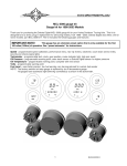
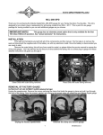
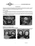
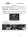
1
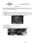
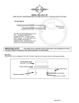
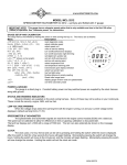
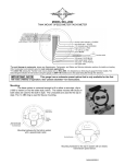
MCL-3006 gauge kit
Thank you for purchasing the Dakota Digital MCL-3006 gauge kit for your Harley Davidson Touring bike. This kit is
designed to be a direct, plug in replacement for all touring models from 2004 – 2012. Dakota Digital also offers a kit for
older models, part number MCL-3000. The kit includes the following gauges and features:
IMPORTANT NOTE!
This gauge has an odometer preset option that is only available for the first
100 miles (160km) of operation. See “preset odometer” for instructions.
Speed - programmable speed calibration, performance menu, two trip meters, odometer, count down service miles,
security and check engine indicators
Tachometer – programmable tach, clock, gear position, cruise control indicator, ABS indicator, and high rpm recall
Oil Pressure – programmable warning point, uses stock sensor or Dakota Digital sensor for higher pressure
Oil Temperature – programmable warning point, complete with new sensor
Volts – programmable warning point
Fuel Level – low fuel warning, uses factory sensor, can be programmed for custom fuel sender
NOTE: The factory ambient air temp gauge is replaced by an oil temperature gauge.
All gauges have automatic night dimming controlled by a sensor in the tachometer.
1
MAN#650227:E
INSTALLATION
Please read and familiarize yourself with all of the components and this manual. The first step is to remove the
seat and disconnect the negative side of the battery, as with any electronic install. Once the battery is disconnected you
are ready to start.
Remove the outer fairing; this will vary from model to model, please follow the service manual to expose the wiring and
gauges. Don’t be alarmed by the amount of wires behind the fairing, this is a direct plug in kit and these detailed
instructions will guide you through it.
Pic of Street Glide with outer fairing removed
Pic of Road Glide with outer fairing removed
REMOVAL OF FACTORY GAUGES
ULTRA FLHT & FLHX (batwing fairings)
Unplug the speedometer and tachometer. Remove the screws securing the clamps that hold the gauges in place and
pull them out through the fairing. Save the screws, gaskets, and clamps to be reused when you install your new
Dakota Digital gauges.
Unplug the factory speed and tach
Unscrew the clamps and remove gauges
ROAD GLIDE FLTR
You will need to remove the speedometer and tachometer instrument bezel. To do this, remove two small screws on
the left and right side of the bezel. Lift up on the back of the bezel and slide the tab that is under the ignition switch out
from under the switch cover, see photos below of ignition switch cover removed to show detail. Unplug the gauge
connections and unplug the indicator lights so the bezel can be completely removed for easier installation of the new
gauges. Remove the clamps that hold the gauges to the bezel and remove the gauges and gaskets.
2
MAN#650227:E
Picture of tab (switch cover removed)
Bezel removed
Gauges/Grommets removed
All of the small gauges, fuel, volts, oil, and air temp have two plugs. One is for illumination the other is for the gauge
power, ground, and sensor. The illumination harness, two pins (orange and black wires), will not be reused and can
hang freely inside the fairing, with the bulb removed, or can be secured to the other gauge wires to clean things up. The
three pin connector will be used to connect all of the new Dakota Digital small round gauges. Unplug connectors at the
back of the four small round gauges, then remove the two 5/16” nuts holding the clamps onto each small gauge and
remove the gauges.
*New nuts for the small gauges are included in the hardware pack DO NOT reuse the stock nuts for the new gauges
they are not the same thread.
Remove the small gauges with 5/16” wrench or nut driver
IMPORTANT NOTE!
SAVE ALL CLAMPS, GASKETS, and SCREWS FROM THE STEPS ABOVE AS THEY WILL BE USED TO SECURE THE NEW
DAKOTA DIGITAL GAUGES
3
MAN#650227:E
Save ALL Clamps, Screws, and Gaskets and reuse for install
Next you are ready to install the new gauges into the fairing. Install the gauges and secure using the original hardware
that was removed: clamps, gaskets, and screws. Small gauges are secured using the original clamps along with the
supplied nuts. The picture on the first page shows the proper location for each gauge. Be sure the alignment tab on
the clamp lines up with the notches in the fairing. Some fairings may only have one notch, line up at least one tab on
the clamp with the notch in the fairing, this will ensure the gauges are centered and aligned correctly.
Speedometer and Tachometer
Oil PSI, Oil Temp, Voltmeter, and Fuel Level
WIRING (plug in connections)
Now you are ready to make the gauge connections. Plug the original speed and tachometer connectors directly into
the new gauges. Plug the original oil pressure, voltage, and fuel connectors directly into the new gauges. Because the
digital fuel gauge is much more accurate than the original fuel gauge, any shifts in the grounding will be more
noticeable. A 10% shift can be seen on the digital fuel gauge due to weak fairing ground connections that would not be
noticeable with the original needle. It is recommended that a new ground wire be run from the fuel gauge to the fuel
sender ground on the tank. Fuel ground harness 394164 is included for this purpose. Instructions and photos are
shown after the oil temperature sensor installation.
The air temperature gauge is replaced with an oil temperature gauge and this connector will need to be changed,
instructions on how to install and connect the sensor begin on the following page.
A two wire harness with six connectors is included. This will plug into the back of each gauge, these wires are the
switch(green) and dim(blue) wires. Route one of these harnesses to the back of each gauge and plug it in. It does not
matter which connector goes to each gauge.
Switch and Dim wire harness
Connect one plug to the back of each gauge
4
MAN#650227:E
OIL TEMPERATURE SENSOR
The only small gauge that requires an additional sender is the oil temp, since this is replacing the air temp gauge. The
supplied oil temperature sensor replaces one of the oil pan plugs. You can do this at an oil change so you do not have
to worry about losing oil, or be quick and you should only lose a small amount of oil. First locate the allen head plug on
the front bottom side of the oil pan. The plug is on the right of the oil pan drain plug that is used to drain the engine oil
for an oil change. It is a 3/8” NPT allen head plug that should be flush with the oil pan. See photo for the correct plug.
NOTE: Check oil level after install of this sensor, refill oil as needed
Oil Temp sensor and harness
Bottom of oil pan
Remove 3/8”npt allen plug
Wipe any road grime and oil from around the plug so the area is clean. Use a 5/16” allen wrench to remove the plug.
Have the sensor ready to thread in so minimal oil is lost. Tighten the new oil temp sensor with a ¾” wrench.
5
MAN#650227:E
Thread sender into oil pan
Tighten temp sensor with a ¾” wrench
Installed oil temp sensor and harness plug
Plug in the sealed two pin connector and route the wires over to the bottom right side frame rail. Begin running the
wires back and up behind the transmission and starter area to the battery box, following the wiring harness that is in
place. Use zip-ties to secure the wire harness to the other wires along the frame.
Once you have the wires up through the battery box area it is recommended you remove the tank bolts to continue
running the harness under the tank. Use a firm wire and some electrical tape to fish the wires up the backbone under
the tank (filler rod/welding wire works well for a fish tape). Once clear of the tank, follow the factory wiring harness on
the right side and route wires behind the fairing and over to the oil temp gauge. Make sure to replace and tighten the
tank bolts when done. If you are going to be routing a new ground wire for the fuel gauge, it should be routed under the
tank at the same time as the oil temperature harness to ease installation.
Remove rear tank bolt
Remove front tank bolts to loosen tank
6
MAN#650227:E
Route wires under tank
Pull the temp sensor wires through the fairing
Now you will have to de-pin a couple wires to connect the temp sensor wires to the factory plug to allow a factory style
plug in connection to the gauge. The pins in the connector have a small locking tab on the back flat side of the terminal
seen in the picture below. Use a small allen wrench/pick/or small screw driver to bend and release this tab. While
pushing on the tab, pull the wire gently out from the back of the connector.
You will need to remove:
Black
pin 2 gauge ground (bottom center location in the housing)
Blue w/ Violet
pin 3 gauge signal (old air temp sensor, right location looking at back of housing)
Insert the RED wire into the previous location of the Blue w/ violet wire. Insert the other BLACK wire, wire with a short
3” pigtail, into the black wires previous location. Slide supplied piece of heat shrink over the pigtail and connect the
spade connector on the black wire to the original gauge ground wire that was removed from the housing. This
provides ground for the gauge and sensor. Heat up the heat shrink to protect the ground connection.
NOTE: See Photos on the following page for more details
Locking tab on terminals
Using a small allen/pick release the locking tab
7
MAN#650227:E
Push gently on the tab to release pin
Remove the pin from the connector
Oil Temp Sensor Plug Connections
8
MAN#650227:E
FUEL GAUGE GROUND UPDATE
The replacement fuel gauge harness ground 394164 is included in your kit. It has a long wire to go to the fuel sender
and a short wire that is only used with 2004-2007 model year speedometers. The factory ground wire on the fuel
gauge should be removed as shown with the oil temp gauge connections on the previous page and the supplied ground
wire put in its place. The other end of the long ground wire should be routed under the tank with the oil temperature
sensor harness. Locate the three or four wire harness going to the fuel pump and fuel sender connector near the gas
cap (shown below). The new fuel gauge ground should be attached to one of the black ground wires on this harness.
Three wire harnesses will have one ground wire and four wire harnesses will have two ground wires, either black
ground wire on the four wire harness can be used. Soldering and covering with heat shrink is the preferred method for
attaching the ground wire but a properly used butt connector will also work. Scotch lock style connectors are not
recommended.
•
•
•
•
Strip back the insulation on the black wire.
Wrap the end of the new fuel gauge harness around the exposed wire.
Solder the connection, making sure the solder flows into the wires.
Wrap the splice with electrical tape to insulate it.
SPEEDOMETER GROUND UPDATE
**2004-2007 model year only.
If you are using the miles to empty function on the speedometer with a 2004-2007 model year, then the speedometer
ground (black wire) will also need to be cut and connected to the newly routed fuel gauge short ground wire. The
original grounding on these models is not sufficient for the miles to empty function to operate correctly.
•
•
•
Locate the 12 pin connector that plugs into the back of the speedometer.
Cut the black or black/green wire a few inches down from the connector.
Connect the speedometer connector side of the wire to the extra, short wire from the fuel gauge harness.
9
MAN#650227:E
FUNCTION SWITCH
The factory speedometer push button switch is used as the main function switch. The function switch allows
access to all of the mileage, rpm, and performance information. Pressing and releasing the function switch toggles
through the different displays. Pressing and holding the switch for about two seconds will reset the current display.
The display sequence for the speedometer is as follows:
SPEED MENU
000000
odometer mileage
A
000.0
trip meter mileage A
trip meter mileage B
B 000.0
S 0000
miles since last service (if programmed)
++++++
Speedometer will show km/h (or MPH if metric)
R 250.0 or range
distance to empty (if turned on)
PERFORMANCE MENU(on speedometer when enabled)
HI 00
high speed recall
60 00.0
0-60 mph time (0- 00.0 0-100kph)
25 00.0
quarter mile time
25 00
quarter mile speed
T 000F
cylinder head temp from ECM (run switch must be on)
The 0-60 and ¼ mile timers are zeroed by pressing and holding the switch while that timer is displayed. The timer will not
restart until the speed reaches zero and then you start driving again.
The function switch can also be used to change the tachometer display. Make sure the speedometer is
displaying the odometer to avoid resetting any of the other settings before attempting to change the tachometer. Press
and hold the switch for about four seconds to change the tach menu. Press and hold the switch for about six seconds
to reset the high rpm recall while it is displayed. The tachometer only has two display modes as follows:
TACH MENU
CLOCK
>
12:00
12 hour clock
HI RPM
>
0000
high rpm recall
GAUGE SETUP AND CALIBRATION
The function switch, discussed above, is used to enter setup mode for all of the gauges. The first step in the
setup procedure is to select which gauge you are going to select to change a setting. Each gauge will either show a
number or a label. If the gauge is showing a label then that gauge will be selected to enter setup. All of the other
gauges will exit setup and allow the selected gauge to be changed. To get into setup press and hold the function
switch while turning the key on. Press and release the switch to advance through the menus below, when on the
desired option press and hold the switch to select setup for that particular gauge/function.
speed
tach
oil psi
oil temp Fuel
volt
st
1
- 1 CL
- 1 - 1 - 1 - 1 nd
2
SPd
- 2 - 2 - 2 - 2 - 2 rd
3
- 3 tCH
- 3 - 3 - 3 - 3 th
4
- 4 - 4 PSI
- 4 - 4 - 4 th
5
- 5 - 5 - 5 F or C
- 5 - 5 th
6
- 6 - 6 - 6 - 6 FUL
- 6 th
7
- 7 - 7 - 7 - 7 - 7 uLt
th
8
- 8 - 8 - 8 - 8 - 8 - 8 FACTORY DEFAULT SETTINGS FOR SETUP MENUS
Below is a list of all of the factory gauge settings and what can be adjusted in the setup menus. You can
calibrate and adjust gauges as often as you wish, however they should only need to be set once. Most gauges will
function properly from the factory only desired warning points may need adjustment. The fuel sender needs to be set
per application as well. The only gauge that may require setting after the initial install is the Clock function on the
tachometer so it is the first setup menu.
Speedometer
Tachometer
Pressure Gauge
Unit
MPH
Clock Cal
0 (range -8 – 7)
Sender
60PSI (user selectable)
Service meter
OFF
Night Dimming
1 (darkest)
HI warn
51 PSI (range varies with sender)
Performance Menu ON
Display Update 3 (fastest 1/8 sec.)
Lo warn
7 PSI (range 02-32 psi)
Fuel
OFF
RPM Warning
5500 (range 2200-9900)
Volt Gauge
Oil Temp Gauge
Fuel Gauge
Lo warn
11.1 V (range 9.6-12.6)
Sender
Set to deg F (user selectable scale)
Sender
10 ohm sender (user selectable)
Hi warn
15.4 V (range 13.9-16.9)
Hi warn
230 F (range 200-290F or 93-143C)
Lo Warn 10% (not adjustable)
10
MAN#650227:E
SPEEDOMETER SETUP
Main Menu
Sub Menu
Description
SPd
dIAG
read diagnostic codes from engine or security modules
AdJvSt
select adjust calibrate speed
vnIt
select speed unit (MPH or km/h)
S SEt
miles to service setting
PErF
enable/disable performance readings
FvEL
setup fuel information
RANGE
setup miles to empty function
-odoMK one-time odometer preset (only shown while odometer has less than 100 miles)
Press and hold the switch while turning the key on. Release the switch. The speedometer will show “-1-”. Press
and release the switch so that “SPd” is displayed. Press and hold the switch for about three seconds until “ - ” is
displayed. Release the switch. The MPH display will show “SEt” and the odometer display will show “dIAG”. Press and
release the switch to move through the different speedometer setup menus. Press and hold the switch to select a menu
option.
dIAG Diagnostics mode for checking/clearing trouble codes
•
•
•
•
Press and release the switch until “dIAG” is displayed, then press and hold the switch until “ - ” is displayed.
Release the switch. The display will show “ENGINE”, “SECvRE”, ”ABS”, or “DoNE”.
Press and release the switch to change the selection, press and hold the switch until “ - ” is displayed to begin reading the stored
codes for the particular system.
Release the switch. The display will show the current codes, “none”, or “no rsp”. Press and release the switch to move to the
next stored code. After all codes are displayed the module part number will be scrolled across the screen. To clear codes, press
and hold the switch when “end” is displayed. Consult a service manual for trouble code descriptions.
AdJ
AdJuSt Speed Calibration
The speedometer is calibrated by the engine computer, but the speedometer reading can be adjusted through the
gauge. The adjustment is set a value from 0.75(75%) – 1.25(125%) with 1.00 being no change.
•
•
•
•
Press and release the switch until “AdJvSt” is displayed, then press and hold the switch until “ - ” is displayed.
Release the switch. The display will show “SLoWJ” or “FASTER”. Slow will make the speedometer read lower, faster will make the
speedometer read higher. Press and release the switch to change the selection, press and hold the switch until “ - ” is displayed
to continue on.
Release the switch. The display will show “CL 1.00” or whatever the current calibration ratio is.
Press and release the switch to change the adjustment ratio. Press and hold the switch until “ - ” is displayed to save the
currently displayed ratio.
vnIt MPH/km/h Selection
•
•
•
•
Press and release the switch until “vnIt” is displayed, then press and hold the switch until “ - ” is displayed.
Release the switch. The display will switch to “vnIt” and light up the current speed unit (MPH or km/h).
Press and release the switch until the desired setting is displayed.
Press and hold the switch until “ - ” is displayed to the setting.
S Se
Set Miles to Next Service setup
•
•
•
•
The service mileage is a countdown mile meter. The service mile display can be disabled or can be set to count down from
500 – 7500 miles. If the service mile is enabled and it gets to 0 miles, it will display “S -DUE” each time the key is turned on. If the
push button switch is pressed and held while “S ----” is displayed, the service miles will be reset.
Press and release the switch until “S SEt” is displayed, then press and hold the switch until “ - ” is displayed.
Release the switch. The current setting will be displayed. (“oFF” or a mileage from 500 – 7500 in increments of 500.)
Press and release the switch until the desired setting is displayed.
Press and hold the switch until “ - ” is displayed to save the setting.
PerF Performance Menu setup
•
•
•
•
The performance readings can be turned on or off. When they are turned off the odometer will only toggle through the
mileage readings.
Press and release the switch until “PErF” is displayed, then press and hold the switch until “ - ” is displayed.
Release the switch. The current setting will be displayed (“on” or “oFF”).
Press and release the switch until the desired setting is displayed.
Press and hold the switch until “ - ” is displayed to save the setting.
11
MAN#650227:E
(Speedometer Setup Continued)
FvEL Fuel sender selection DEFAULT OFF
•
•
•
•
•
This setting should be set to “oFF”, this may be used for future accessories. The options are to allow the fuel information to be
introduced to the data bus. This menu is not really important but is here in case future accessories require it. You should not
harm anything if the settings are incorrect, but OFF is the default setting at this point.
Press and release the switch until “FvEL” is displayed, then press and hold the switch until “ - ” is displayed.
Release the switch. The current setting will be displayed (“oFF” or “on”).
Press and release the switch until the desired setting is displayed.
Press and hold the switch until “ - ” is displayed to save the setting.
If “on” is selected, then “done”, “test”, “reset”, or “adjust” options will be displayed. “TEST” shows the current fuel reading.
“RESET” and “ADJUST” change the fuel data sent on the bus and will not normally need to be changed.
Press and release the switch until “done” is displayed. Press and hold the switch until “ - ” is displayed to exit.
•
RANGE Distance to Empty setup
The range reading will initially show the word “range”until a tank of gas has been driven to allow the gauge to complete its
setup based on your driving. Begin with a full tank of gas and do not refill it until it gets below ¼ tank of gas. This can be done on
multiple trips as long as no fuel is added before it gets low enough. After the initial setup the display will show “r” followed by the
calculated distance to empty. This will count down, making adjustments as necessary, until the range is 35 miles (56km) or less and
then it will show “r Lo”. The gauge will continue to make adjustments to match your driving habits with each fill up. After the initial
setup you are not required to wait for the fuel to get below ¼ tank before refilling.
•
Press and release the switch until “RANGE” is displayed, then press and hold the switch until “ - ” is displayed.
•
The display will show “oFF” or “oN”. Press and release the switch to change to the desired setting.
• Press and hold the switch until “ - ” is displayed to select the setting.
• “OFF” turns the range display off.
• Turning the function on will access the following menus
o donE
(exits the setup)
o rESEt
(resets the gauge to beginning of the initial range learning)
o sender
(used to change or reset the fuel gauge readings)
d10
(set to 2004 – 2007 model with Dakota Digital fuel gauge)
d33
(set to 2008 – 2012 model with Dakota Digital fuel gauge)
H04
(set to 2004 – 2007 factory fuel gauge)
H08
(set to 2008 – 2012 factory fuel gauge)
d-C
(set to a custom fuel curve with Dakota Digital fuel gauge)
• SET 00
(set new empty reading, “done” indicates it was stored, “error” indicates the
signal is out of range)
• SET 99
(set new full reading)
CSt
(set to a custom fuel curve with factory fuel gauge)
• SET 00
(set new empty reading, “done” indicates it was stored, “error” indicates the
signal is out of range)
• SET 99
(set new full reading)
•
Press and release the switch to select the desired fuel setup menu, press and hold it until “ - ” is displayed, and then release the
switch to view or go on.
•
A press and hold will save the setting or exit back to the menu.
•
“done” is the first menu displayed, a press and hold will exit fuel set up at this point.
•
“rESEt” will begin the initial range learning again. You must begin with a full tank of gas and then ride it down to less than ¼ tank.
This can be done in multiple trips as long as the tank is not filled in between. The range display will show “range” until this is
completed and then begin showing the distance to empty.
•
“SENDER” is used to select the type of fuel sender and gauge being used to allow the speedometer to read the fuel level accurately.
12
MAN#650227:E
(Speedometer Setup Continued)
odoMK Odometer preset
•
•
•
•
•
•
The odometer can be preset by the customer within the first 100 miles. Once the odometer has more than 100 miles the
menu option will no longer be displayed. Make sure you have correctly selected the units to be either MPH or km/h first. The
odometer will be set in the selected units. Once you have preset the miles you cannot change it again. WARNING!!: This only
allows setting odometer to the nearest mile. Do not use tenths! For example a mileage of 65432.1 should be set to
“065432” using this method. If the tenths digit is used, the odometer will read 10 times too high.
Press and release the switch until “-odoMK” is displayed, then press and hold the switch until “ - ” is displayed.
The current miles will be displayed with the left most digit flashing.
Press and release the switch to increment the digit. Press and hold the switch to move to the next digit to the right.
Continue until the right most digit has been set. Press and hold the switch and the speed display will show “No”.
Press and hold the switch while “no” is displayed to go back and continue changing the odometer display. Turn the key off to
cancel any changes.
Press and release the switch to change to speed display to “yes”. Press and hold the switch while “yes” is displayed to save the
current odometer reading.
TACHOMETER SETUP
Main Menu
Sub Menu
CL
tCH
nIgHt
vPdAtE
WXArn
gEAr
Description
set clock time
set night dimming level
set rpm update rate for digital readout
set rpm shift warning point
transmission gear programming
Press and hold the switch while turning the key on. Release the switch. Press and release the switch until “tCH” is displayed,
then press and hold switch until “ - ” is displayed. The rpm display will show “Set” and the lower display will show “night”. Press and
release the switch to move through the different menus, press and hold the switch to select a menu option.
Note: The tachometer calibration may require you to hold the switch while starting the bike, but only if you are
going to adjust/set the GEAR programming since you will have to ride the bike. Some ignition systems may disrupt power
to other circuits, when cranking, causing the gauge to reset, this is why you must hold the switch while starting if you are
setting up the GEAR display. All other gauge functions and gauges can be set without running the engine.
CL CLOCK SETUP
•
•
•
•
•
•
•
•
The time is displayed on the smaller display below the RPM, and is the first setup menu since it is the only setting that requires
change once the initial calibrations are complete.
To set the clock, press and hold the switch while turning the key on. Release the switch.
The RPM display should show “CL” , press and hold switch until “ - ” is displayed.
Release the switch. The lower display will show the current hours.
Press and release the switch to change the hours, press and hold the switch to change to the minutes.
Release the switch. The lower display will show the current minutes.
Press and release the switch to change the minutes, press and hold the switch to change to the time adjust calibration.
Release the switch. The lower display will show “CAL” and a number from -8 to 7. This allows the clock to be adjusted +/seconds per day.
Press and release the switch to change the CAL value, press and hold the switch to save this and exit the clock setup.
nIgH
nIgHt NIGHT DIMMING
•
•
•
•
Your display system has a dimming feature that dims the display intensity. Normally the system is at full brightness for
daytime viewing. The tachometer has a light sensor that will provide a signal to the other gauges to reduce the brightness at
night. The level of darkness before the gauges dim can be adjusted in the tachometer setup.
Press and release the switch until “nIgHt” is displayed, then press and hold the switch until “ – ” is displayed.
Release the switch. The update setting will be displayed. (1=late(darkest), 2=mid, 3=early(lightest), OFF).
Press and release the switch until the desired setting is displayed.
Press and hold the switch until “ - ” is displayed to save the setting.
vPdAtE Display update setup
•
•
•
•
The display update will select how quickly the tachometer reading will respond.
Press and release the switch until “vPdAtE” is displayed, then press and hold the switch until “ - ” is displayed.
Release the switch. The update setting will be displayed. (1=slow, 2=mid, 3=fast).
Press and release the switch until the desired setting is displayed.
Press and hold the switch until “ - ” is displayed to save the setting.
13
MAN#650227:E
(Tachometer Setup Continued)
WXArn Rpm warning setup
•
•
•
•
Press and release the switch until “WXArn” is displayed, then press and hold the switch until “ - ” is displayed.
Release the switch. The current warning point will be displayed.
Press and release the switch until the desired setting is displayed.
Press and hold the switch until “ - ” is displayed to save the setting.
gEAr Gear indicator setup
•
•
•
•
•
•
•
•
•
•
This gauge has a single digit display for gear position. The gauge can learn the gear ratios based on speed and rpm so no
sensors are needed, just what you’ve already connected. It will work with 4, 5, 6, or 7 speed transmissions. The factory preset
option will preset the indicator to work with a stock 5 or 6 speed drive train. With a stock 6 speed there will be a slight delay the
first time you shift to sixth gear as the system verifies the gear. You can also program each gear position for aftermarket
transmissions or if you’ve changed wheel size or sprocket size. To program the gear positions, begin at a section of road where
you can gradually shift through all of the gears. Press and hold the switch while turning the key on and starting the engine. Once
the engine is running, release the switch.
Press and release the switch until “tCH” is displayed. Press and hold the switch until “ - ” is displayed.
Press and release the switch until “gEAr” is displayed, press and hold the switch until “ - ” is displayed.
The display will show “off”, “PRESET”, or “Learn”. “oFF” will disable the indicator. “PRESET” will set the indicator for an original
factory transmission. “LEARN” allows it to work with virtually any transmission option.
To program each gear individually, press and release the switch until “Learn” is displayed, then press and hold the switch.
The message will show “LO TCH” if the engine rpm is below 1500, or “LO SPD” if the vehicle speed is below 5 MPH.
st
Begin driving in 1 gear. The display should show “GEAR 1” and the “1” should be flashing. Drive at a steady speed until the “1”
goes steady and then changes to a flashing “2”, it should only take about 20 seconds if the speed and RPMs are steady.
Optional: If the gear does not stop flashing you can manually override and jump to the next gear by pressing and
releasing the switch to store the gear position quicker.
nd
Shift to 2 gear and drive at a steady speed.
Wait until the “2” goes steady and then changes to a flashing “3”. Shift to 3rd gear.
Optional: If the gears do not stop flashing you can manually override and jump to the next gear by pressing and releasing
the switch to store the gear position quicker.
Repeat this through each gear. When you are done, come to a complete stop or press and hold the switch until the display shows
“donE” and then release it.
Press and release the switch to restart the gauges in normal operation, verify the gear position by riding through each gear and
seeing if positions agree.
OIL PRESSURE SETUP
•
•
•
•
•
•
•
•
•
•
•
The oil pressure gauge can be set for various stock Harley pressure senders. There is a display update setting for how fast
the numbers will change, as well as a user settable low and high pressure warning points. When a warning condition is reached
the gauge will flash the reading as a warning indicator. The stock sender for 1999 and up should be the 60 psi sender. For higher
pressure and more accurate pressure readings one of two Dakota Digital senders may be used: 0-75 psi SEN-1032, or 0-150 psi
SEN-1031.
To enter setup, press and hold the switch while turning the key on.
Release the switch. The gauge will show “-1-”.
Press and release the switch until “PSI” is displayed, then press and hold the switch until “Snd“ is displayed.
Press and release the switch until the correct sender type is displayed. “40” for ’96-’98 stock sender, “60
60”
60 for ’99-up stock
sender, “75” for Dakota Digital 75 psi, “150” for Dakota Digital 150 psi.
Press and hold the switch until “Lo” is displayed, then release the switch.
Press and release the switch until the desired low pressure warning point is displayed.
Press and hold the switch until “HI” is displayed, then release the switch.
Press and release the switch until the desired high pressure warning point is displayed.
Press and hold the switch until “SPd” is displayed, then release the switch.
Press and release the switch to change the update rate between fast “FSt” and slow “SLO”.
Press and hold until “---” is displayed to save the settings. Turn the key off.
OIL TEMPERATURE SETUP
•
•
•
•
•
•
•
The oil temp gauge has a user selectable high temperature warning point that can be set so the gauge will flash the reading
when the temp is met or exceeded. The gauge will only read correctly with the supplied sender.
To enter setup, press and hold the switch while turning the key on.
Release the switch. The gauge will show “-1-”.
Press and release the switch until “ F ” or “ C ” is displayed, then press and hold the switch until “Snd” is displayed.
Press and release the switch to change between Fahrenheit “F
F” and Celsius “C”.
Press and hold the switch until “HI” is displayed, then release the switch.
Press and release the switch until the desired high temperature warning point is displayed.
Press and hold until “---” is displayed to save the settings. Turn the key off.
14
MAN#650227:E
FUEL SETUP
•
•
•
•
•
•
•
•
•
•
The fuel gauge can be set to read two stock Harley sensor curves, see setup procedure below for correct sender selection.
There is also a non-adjustable warning feature that will flash the gauge at any reading below 10% as a low fuel warning indicator.
To enter setup, press and hold the switch while turning the key on.
Release the switch. The gauge will show “-1-”.
Press and release the switch until “FUL” is displayed, then press and hold the switch until “Snd” is displayed.
Press and release the switch until the correct sender type is displayed. “10
10”
33”
10 for 73-10, “33
33 for 240-33, “CUS” for custom or “CAL”
for custom sender programming. The stock fuel sender (2004-2007) should use the “10
10”
10 setting for correct readings or
“33
33”
33 for 2008. If “CAL” is not selected, press and hold until “---” is displayed. Turn the key off.
If “CUS” is selected, and a custom fuel curve has not yet been programmed, the gauge will immediately enter the “CAL” routine.
If “CAL” is selected, the fuel sender curve can be programmed into the gauge. Begin with an empty tank. The gauge will be
showing “-00” and switch to displaying the measured resistance. Press and release the switch to save the empty reading.
The display will show “-33” and then switch to displaying the measured resistance. Add enough fuel to fill the tank to 1/3. Press
and release the switch to save the 1/3 reading.
The display will show “-66” and then switch to displaying the measured resistance. Add more fuel to fill the tank to 2/3. Press and
release the switch to save the 2/3 reading.
The display will show “-99” and then switch to displaying the measured resistance. Add more fuel to fill the tank full. Press and
release the switch to save the full reading.
Press and hold until “don“ is displayed to save the settings. The gauge will then return to normal operation.
VOLT SETUP
•
•
•
•
•
•
•
The volt gauge has user settable low and high voltage warning points that will make the gauge flash as a warning indicator
when either of the conditions are met or exceeded.
To enter setup, press and hold the switch while turning the key on.
Release the switch. The gauge will show “-1-”.
Press and release the switch until “vlt” is displayed, then press and hold the switch until “ Lo” is displayed.
Press and release the switch until the desired low voltage warning is displayed.
Press and hold the switch until “HI” is displayed, then release the switch.
Press and release the switch until the desired high voltage warning point is displayed.
Press and hold until “---” is displayed to save the settings. Turn the key off.
Speedometer Troubleshooting guide.
Problem
Possible cause
Gauge will not light up
Orange wire does not have power.
Black wire is not getting a good ground.
Gauge is damaged.
Gauge lights up, but speed No data from ECM.
will only show zero.
Speed sensor not grounded properly.
Speed reading is erratic or
jumps around.
Speed reading is incorrect.
Gauge will not dim.
Gauge remains dim at all
times.
Security indicator does
not work.
Engine indicator does
not work.
ECM performance tune
or reprogramming fails.
Sensor is not sending a speed signal.
Speed sensor wire is loose or broken.
Poor ground connection.
Ignition Interference
Gauge is not calibrated correctly.
Blue wire (2-pin harness) is not connected
correctly.
Blue wire (2-wire harness) is getting power all
all of the time.
Loose or incorrect connection to indicator wire.
No data from ECM.
Stock service tools look for all stock gauges.
15
Solution
Connect to a location that has power.
Connect ground to a different location.
Return gauge for repair. (see instructions)
Check engine trouble codes.
Move ground to different location, preferable close to the
speedometer ground.
Check for a damaged or malfunctioning speed sensor.
Check all wire connections and inspect wire for breaks.
Check ground connection on speedometer and sensor.
Check for tachometer wires routed with VSS signal wires.
Check for VSS signal wires routed near ignition coils
Check for poor ignition system ground
Use suppression spark plug wires
Gauge must be calibrated (see instructions).
Check wiring connections. Blue wire should have 12 volts
when tachometer is dim.
Check wiring connections. Blue wire should have 0 volts
when tachometer is bright.
Check that the appropriate indicator wire has about 0 volts
when the indicator should be off and about 12 volts when
the indicator should be on.
Check engine trouble codes.
Unplug MCL-3006 and reprogram ECM. MCL-3006 can be
plugged back in as soon as reprogramming is complete.
MAN#650227:E
Tachometer Troubleshooting guide.
Problem
Possible cause
Gauge will not light up
Orange wire does not have power.
Black wire is not getting a good ground.
Gauge is damaged.
Gauge lights up, but tach
No data from ECM.
will only show zero.
Tach reading is erratic or
Tach signal wire is loose or broken.
jumps around.
Poor ground connection.
Gear indicator is always “*”
Gauge will not dim.
Gauge remains dim at all
times.
Gauge will not enter setup.
Cruise Engage indicator
does not work.
ECM performance tune
or reprogramming fails.
Update rate is too fast.
Gears not programmed.
Night dimming is turned off or too low.
Night dimming is turn too high.
Light sensor at bottom of gauge is covered.
Green wire (2-wire harness) is not connected
correctly.
Loose or incorrect connection to indicator wire.
Stock service tools look for all stock gauges.
Small gauge Troubleshooting guide.
Problem
Possible cause
Gauge will not light up
Orange wire does not have power.
Black wire is not getting a good ground.
Gauge is damaged.
Gauge reading is erratic or
Gauge signal wire is loose or broken.
jumps around.
Poor ground connection.
Gauge reading is incorrect. Gauge is set up for wrong sensor type.
Poor gauge grounding.
Gauge will not dim.
Blue wire (2-pin harness) is not connected
correctly.
Gauge remains dim at all
Blue wire (2-wire harness) is getting power all
times.
all of the time.
Gauge will not enter setup.
Green wire (2-wire harness is not connected
correctly.
Solution
Connect to a location that has power.
Connect ground to a different location.
Return gauge for repair. (see instructions)
Check engine trouble codes.
Check all wire connections and inspect wire for breaks.
Check ground connection on tachometer, engine, and ignition
system.
Reset display update speed slower.
Program gear indicator in setup. (see instructions)
Change “night” setting in setup. (see instructions).
Change “night” setting in setup. (see instructions).
Make sure the lower part of the lens is not covered.
Check wiring connections. Green wire should have 12 volts
when the switch is pressed.
Check that the appropriate indicator wire has about 12 volts
when the indicator should be off and about 0 volts when the
indicator should be on.
Unplug MCL-3006 and reprogram ECM. MCL-3006 can be
plugged back in as soon as reprogramming is complete.
Solution
Connect to a location that has power, check fuses.
Connect ground to a different location.
Return gauge for repair. (see instructions)
Check all wire connections and inspect wire for breaks.
Check ground connection on gauge, engine, and sensor.
Change sensor setting in setup. (see instructions).
Repair or replace ground wire.
Check wiring connections. Blue wire should have 12 volts
when tachometer is dim.
Check wiring connections. Blue wire should have 0 volts
when tachometer is bright.
Check wiring connections. Green wire should have 12 volts
when the switch is pressed.
SERVICE AND REPAIR
DAKOTA DIGITAL offers complete service and repair of its product line. In addition, technical consultation is available to help you work through any questions or
problems you may be having installing one of our products. Please read through the Troubleshooting Guide. There, you will find the solution to most problems.
Should you ever need to send the unit back for repairs, please call our technical support line, (605) 332-6513, to request a Return Merchandise Authorization
number. Package the product in a good quality box along with plenty of packing material. Ship the product by UPS or insured Parcel Post. Be sure to include the RMA number
on the package, and include a complete description of the problem with RMA number, your full name and address (street address preferred), and a telephone number where you
can be reached during the day. Any returns for warranty work must include a copy of the dated sales receipt from your place of purchase. Send no money. We will bill you after
repair.
Dakota Digital 24 Month Warranty
DAKOTA DIGITAL warrants to the ORIGINAL PURCHASER of this product that should it, under normal use and condition, be proven defective in material or
workmanship within 24 MONTHS FROM THE DATE OF PURCHASE, such defect(s) will be repaired or replaced at Dakota Digital’s option.
This warranty does not cover nor extend to damage to the vehicle’s systems, and does not cover removal or reinstallation of the product. This Warranty does not
apply to any product or part thereof which in the opinion of the Company has been damaged through alteration, improper installation, mishandling, misuse, neglect, or accident.
This Warranty is in lieu of all other expressed warranties or liabilities. Any implied warranties, including any implied warranty of merchantability, shall be limited to
the duration of this written warranty. Any action for breach of any warranty hereunder, including any implied warranty of merchantability, must be brought within a period of 24
months from date of original purchase. No person or representative is authorized to assume, for Dakota Digital, any liability other than expressed herein in connection with the
sale of this product.
16
MAN#650227:E