1
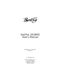
HP1000 HP2000 Curtain Eyelet Machines 25mm, 40mm & 66mm Eyelets User Manual For The HP Range of Curtain Eyeleting Machines (Using separate cutting and closing dies) IMPORTANT Health & safety information contained within; read this manual before use March 05 MACHINE USE This machine allows the user to cut the correct size circular hole in material by using the cutting tools (fig 2) and then by changing the toolage, to set an eyelet and ring in that hole (fig 3). TOP CLOSING DIE “V” CUTTER CUTTING RING BOTTOM CLOSING DIE Figure 1 Figure 2 IMPORTANT SAFETY INFORMATION · · · · · Be aware that there are sharp cutting edges on the dies Keep hands away from cutters, punches and dies when applying pressure. Ensure the operating arm is fully rotated to the rear of the press to prevent it falling forward before changing or adjusting toolage or placing material and eyelets for setting. We advise that when using any machinery suitable gloves and eye protection should be worn. Always follow maintenance routines explained in the maintenance section. For machines supplied without standard base Before use, this equipment must be securely bolted to a suitable bench using the fixing holes at the rear of its base (fig 1). Figure 3 If you are unsure about using any aspect of this equipment, please consult your supplier. © Copyright 2004 Page 2 SETTING UP AND USING THE “V” CUTTER Step1 Step 2 Fit the spigot in to the base of the machine and tighten the retaining screw. Step 4 (Important Step!) Gently lower the “V” cutter until it makes contact with cutting ring then retighten the base plate screws. If this centralisation step is not carried out correctly it will lead to a damaged cutter! © Copyright 2004 Insert the v cutter in to the column & tighten the retaining screw then place the cutting ring over the spigot. Step 5 Place the material over the cutting ring in the desired position. Then using the lever, lower the v cutter down until it touches the ring. Then apply firm pressure to cut the material Step 3 The toolage must now be centralised. To do this loosen base plate screws Step 6 Lift the v cutter out of the way and remove the waste material. Repeat step 5 to make further holes as desired. Page 3 SETTING UP AND USING THE CLOSING TOOLS Step 1 Step 2 Remove the “V” cutter and replace with the top closing die. Step 4 Lift the cutting ring of the spigot and replace with the bottom cutting die. Step 5 Place the hole over the eyelet with the material face side up. © Copyright 2004 Take an eyelet and sit it on the bottom die, pressing it down as far as it will go. Step 3 Place a ring with its spikes facing upwards on the on the bottom die. Step 6 Lower the top closing die down until it makes contact with the eyelet then apply firm pressure with the lever to cause the eyelet to push through the material and roll around the ring. Page 4 SETTING UP AND USING THE CLOSING TOOLS (CONTINUED) Step 10 Step 11 Lift the closing punch clear of the base die to reveal the set eyelet Inspect the eyelet to ensure it has correctly gripped the material. SUPPLEMENTARY INFORMATION As you cut the holes, the waste material will collect in the cutting ring; periodically lift the ring off the spigot and remove this material to maintain effectiveness. © Copyright 2004 The cutting ring has two cutting edges, when one side becomes blunt simply turn the ring over and use the other side. When both sides have become blunt they can be resharpened by grinding the flat surfaces on each side. Page 5 SETTING UP AND USING THE MATERIAL LOCATION STOPS. (Cost option available for models sold after Oct 2004) BACK STOP SIDE STOP PIN FIXING SCREWS SIDE STOP SLIDE This machine can be supplied with the optional material location stops that assist the operator in correctly positioning the holes in the material. The stop assembly is attached to the machine with two fixing screws on the base plate. To adjust either stop use the 5mm hexagon key supplied with the machine. The back stop is used to set the distance of the hole from the edge of the material. The side stop controls the distance between each of the eyelet holes. This is achieved by setting the side stop pin to the desired distance then placing the previously cut hole over this pin while the next hole is cut. It is recommended that the operator practices with some waste material first to prevent errors in calculating the position of the eyelets. MAINTENANCE 1. Regularly oil moving part lightly (be careful not allow oil to come into contact with areas that may touch curtain fabric) 2. To ensure correct and safe operation there must be no sideways movement in the vertical square rod that holds the top dies. With use over time the adjusting screws on the front and side of the machine may need to be tightened to remove any looseness in the rod and also to prevent the handle from falling © Copyright 2004 Page 6