1
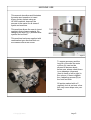
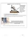
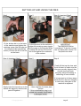
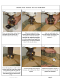
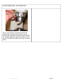
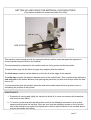
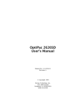
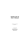
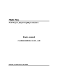
HP1000 HP2000 Curtain Eyelet Machines 25mm, 40mm & 66mm Eyelets User Manual For The HP Range of Curtain Eyeleting Machines with: COMBINATION DIES IMPORTANT Health & safety information contained within; read this manual before use March 05 MACHINE USE This manual describes and illustrates the setup and operation to insert 40mm curtain eyelets using an HP1000 machine; however the process is the same for all sizes of eyelet and machine. This machine allows the user to insert eyelets in their chosen material. By changing the dies (fig 1) different size eyelets can be fitted. TOP DIE BOTTOM DIE Bottom die SPIGOT This machine has been supplied with combination type dies that both cut the material and fit the eyelet. Figure 1 A C B To ensure accuracy and the long life of the dies the main column (A) must not be allowed to become slack; before use, always check there is no sideways movement (front to back or left to right) in the column; if there is tighten the 4 adjusting screws (B) on the front and side. Oil points marked with a C regularly, but do not over oil as this may cause drips onto your fabric. Figure 2 © Copyright 2004 Page 2 IMPORTANT SAFETY INFORMATION THE SAFE POSITION Ensure the operating arm is fully rotated to the rear of the press (known as the Safe Position see fig 3) to prevent it falling forward before changing or adjusting toolage or placing material and eyelets for setting. figure 3 · · · · Be aware that there are sharp cutting edges on the dies Keep hands away from dies when applying pressure. We advise that when using any machinery suitable gloves and eye protection should be worn. Always follow maintenance routines explained in the maintenance section. For machines supplied without standard base Before use, this equipment must be securely bolted to a suitable bench using the fixing holes at the rear of its base Figure 4 If you are unsure about using any aspect of this equipment, please consult your supplier. © Copyright 2004 Page 3 SETTING UP AND USING THE DIES Step1 Step 2 Fit the bottom die in to the base Fit the top die in to the column & of the machine and tighten the retaining screw (the flat edge on tighten the retaining screw (again the flat edge on the die should be the die should be towards the screw). Ensure the die is sat flat towards the screw). Ensure the die is flat against the underside on the base. of the column. Step 4 (Important Step!) Step 5 Step 3 (Important Step!) IMPORTANT The dies must now be centralised. To do this, loosen the two base plate screws. So the plate can move. Step 6 Finally lift the top die clear and then relower to make sure the dies are correctly aligned; they should close and open smoothly without bumping or deflecting off one another. It is important to do these steps each time the dies are changed or when any other part of the machine is adjusted. Gently lower the top die on to the bottom die spigot so that the two parts fit together…. © Copyright 2004 …..then retighten the base plate screws If this centralisation step is not carried out correctly it will lead to a damaged cutter! Page 4 USING THE TOOLS TO CUT AND SET Step 1 Step 2 Place a ring with its spikes facing upwards on the bottom die (it should locate in the recess)….. …..Place the material in the desired position where you want the eyelet over the bottom die and ring, the material should be face side up. Lower the top die on to the material and apply firm pressure until it cuts the material then lift the top die clear….. Step 4 Step 5 Lower the top down until it makes …..Lift the closing punch clear of contact with the eyelet then apply the base die to reveal the fitted firm pressure with the lever to eyelet cause the eyelet to push through the material and roll around the ring….. © Copyright 2004 Step 3 ……take an eyelet and sit it over the bottom die spigot that is now visible through the material…. Step 6 Inspect the eyelet to ensure it has correctly rolled and firmly gripped the material. Page 5 SUPPLEMENTARY INFORMATION As you cut the holes, the waste material will collect within the body of the top die, use the hexagon key supplied to push this waste material out. If waste material is allowed to build up in the top die it will affect the ability of the dies to set the eyelet. © Copyright 2004 Page 6 SETTING UP AND USING THE MATERIAL LOCATION STOPS. (Cost option available for models sold after Oct 2004) BACK STOP SIDE STOP PIN FIXING SCREWS SIDE STOP SLIDE This machine can be supplied with the optional material location stops that assist the operator in correctly positioning the holes in the material. The stop assembly is attached to the machine with two fixing screws on the base plate. To adjust either stop use the 5mm hexagon key supplied with the machine. The back stop is used to set the distance of the hole from the edge of the material. The side stop controls the distance between each of the eyelet holes. This is achieved by setting the side stop pin to the desired distance then placing the previously cut hole over this pin while the next hole is cut. It is recommended that the operator practices with some waste material first to prevent errors in calculating the position of the eyelets. MAINTENANCE 1. Regularly oil moving part lightly (be careful not allow oil to come into contact with areas that may touch curtain fabric) 2. To ensure correct and safe operation there must be no sideways movement in the vertical square rod that holds the top dies. With use over time the adjusting screws on the front and side of the machine may need to be tightened to remove any looseness in the rod and also to prevent the handle from falling © Copyright 2004 Page 7