1
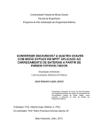
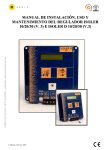
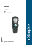
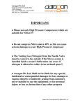
Commercial offices
Montalbán, 9
28014 - Madrid
Spain
Tel.: 34 91 531 26 25
Fax: 34 91 531 10 07
[email protected]
R.M. MÁLAGA T. 496. L. 364 F. 92. H. 2497 - A-29072931. © Note: Isofotón, S.A., reserves the right to make any amendments to this leaflet.
INSTALLATION, USE AND MAINTENANCE MANUAL FOR
THE STANDARD RANGE OF ISOFOTON
PHOTOVOLTAIC MODULES
1st Edition, September 2003
- Page 1/13. Appendix II -
Commercial offices
Montalbán, 9
28014 - Madrid
Spain
Tel.: 34 91 531 26 25
Fax: 34 91 531 10 07
[email protected]
R.M. MÁLAGA T. 496. L. 364 F. 92. H. 2497 - A-29072931. © Note: Isofotón, S.A., reserves the right to make any amendments to this leaflet.
CONTENT
1. INTRODUCTION.......................................................................................................................3
2. TECHNICAL DATA ...................................................................................................................3
3. PROTECTION DIODES............................................................................................................6
4. CONNECTION BOXES.............................................................................................................6
5. RECOMMENDATIONS FOR USE ..........................................................................................8
6. WARNINGS AND ELECTRICAL RISKS ...............................................................................9
7. SERIES MODULE CONNECTION LIMIT............................................................................9
8. PARALLEL MODULE CONNECTION AND WIRING CROSS SECTION.........................9
9. MAINTENANCE OF THE PHOTOVOLTAIC GENERATOR ...........................................10
10. POSSIBLE FAULTS .................................................................................................................11
11. CERTIFICATES ......................................................................................................................12
1st Edition, September 2003
- Page 2/13. Appendix II -
Commercial offices
Montalbán, 9
28014 - Madrid
Spain
Tel.: 34 91 531 26 25
Fax: 34 91 531 10 07
[email protected]
1. INTRODUCTION AND GENERAL RECOMMENDATION
Isofoton, a Spanish pioneering company leading the photovoltaic sector, has been making cells and
modules since it was founded in 1981. Due to long experience using top class materials and thorough
quality controls, the photovoltaic modules made by Isofoton have a useful life of over 20 years with
optimum performance from the first to the last day.
R.M. MÁLAGA T. 496. L. 364 F. 92. H. 2497 - A-29072931. © Note: Isofotón, S.A., reserves the right to make any amendments to this leaflet.
Please read all the instructions in this document carefully before installing, connecting and handling
the photovoltaic module. The recommendations given for one photovoltaic module may be extended
to more than one.
Isofoton will not be held responsible in any way in the event of loss, breakage, damage or additional
cost, due to mishandling of the product by personnel alien to this company.
2. TECHNICAL DATA
The photovoltaic modules manufactured by Isofoton, use high efficiency, pseudo-square monocrystalline
silicon cells to turn solar radiation energy into direct current electric power.
The cell circuit is laminated using E.V.A. (ethylene-vinyl acetate) as a capsulant, in an assembly formed
by a tempered glass at its front and plastic polymer (TEDLAR) at the rear, which provides resistance
against environmental agents and electric insulation.
The laminate fits into an anodised aluminium structure. The IP-65 protected terminal boxes are made
from high temperature resistant plastics and contain terminals, connection terminals and protection
diodes (by-pass diodes).
The frame has several fastening holes for securing the module to the support structure and its earthing
if necessary.
Figure 1 schematically shows the section of a photovoltaic module.
E.V.A. capsulant
Tempered glass
High quality
Polyethylene
foam
Anodised
Aluminium
framework
TEDLAR cover
Cell
Electric
connection
among cells
Fastening holes
Figure 1: Section of a photovoltaic module
1st Edition, September 2003
- Page 3/13. Appendix II -
Commercial offices
Montalbán, 9
28014 - Madrid
Spain
Tel.: 34 91 531 26 25
Fax: 34 91 531 10 07
[email protected]
The electrical values are obtained under standard measuring conditions which correspond to a 1000
W/m2 irradiance, 1.5 M.A. spectrum and 25ºC cell temperature.
However, the modules’ actual working conditions once installed may be very different to laboratory
conditions and, therefore, it is advisable to find out the variations that may occur in order to carry out
the pertinent corrections in calculations.
R.M. MÁLAGA T. 496. L. 364 F. 92. H. 2497 - A-29072931. © Note: Isofotón, S.A., reserves the right to make any amendments to this leaflet.
Besides, whilst a photovoltaic module generated current is proportional to the intensity of solar radiation,
the voltage varies with cell temperatures. Both effects are shown in the following figures.
Figure 2. - Figure 2. - I-V curve variation as a function of incident solar irradiance at constant cell temperature.
Figure 3. - I-V variation curve as a function of the cell temperature at constant incident radiation
1st Edition, September 2003
- Page 4/13. Appendix II -
Commercial offices
Montalbán, 9
28014 - Madrid
Spain
Tel.: 34 91 531 26 25
Fax: 34 91 531 10 07
[email protected]
The variation in the electrical magnitudes of the modules with temperature is as follows:
- The voltage drops at a rate of 2.22 mV/ºC for each series cell contained in the module, and
every degree over and above 25º C.
- The current increases at the rate of 17mA/cm2·ºC of parallel cell area and every degree over
and above 25º C.
R.M. MÁLAGA T. 496. L. 364 F. 92. H. 2497 - A-29072931. © Note: Isofotón, S.A., reserves the right to make any amendments to this leaflet.
It must be borne in mind that the temperature of the cell to which we have been referring, does not
coincide with the ambient temperature due to the cell heating up when sunlight falls hereon.
The increase in the cell’s temperature compared to the air temperature depends on its characteristics
and the actual characteristics of the module itself.
Depending on the incident radiation, the temperature and the load it is supplying, a photovoltaic module
may work at different currents and voltages.
Figure 4 schematically shows a characteristic I-V curve of a photovoltaic module together with the
generated power curve and two different working points, A and B.
Figure 4. - Characteristic I-V curve and generated power curve.
It can be seen that the closer to the maximum power voltage we can make the photovoltaic module
work, the greater will be the power we shall obtain from it.
To summarise, depending on solar radiation, the temperature of the cells and of the equipment to which
connected, a photovoltaic module will generate a certain current at a certain working voltage, the
product of which will set the power generated by the module.
Appendix II to this guarantee shows the characteristic I-V curves for each model depending on incident
irradiation and cell temperature, as well as the physical features of each model.
Under normal conditions, a photovoltaic module with monocrystalline silicon cells is likely to produce
more current and/or voltage than that specified under standard conditions. In these cases, the values
of Isc and Voc may be multiplied by a factor of 1.25, and components such as fuses, conductors and
controllers must be adapted to the photovoltaic generator’s output. (UL 1703 Standard).
1st Edition, September 2003
- Page 5/13. Appendix II -
Commercial offices
Montalbán, 9
28014 - Madrid
Spain
Tel.: 34 91 531 26 25
Fax: 34 91 531 10 07
[email protected]
3. PROTECTION DIODES
The shading of a cell may give rise to a reverse voltage therein. This cell would therefore consume a
power generated by the remainder in series, and an unwanted heating of the shaded cell would occur.
This effect, called the hot point effect, will be all the greater at its highest incident radiation is on the
rest of the cells, and that received by this cell will be less due to the shade. In an extreme case, the cell
could break up due to over-heating.
R.M. MÁLAGA T. 496. L. 364 F. 92. H. 2497 - A-29072931. © Note: Isofotón, S.A., reserves the right to make any amendments to this leaflet.
The use of protection or by-pass diodes reduces the risk of the shaded cells heating up, by limiting the
current which can run through them and thus preventing their breaking.
In general, modules with 24 or more series cells made by Isofoton are supplied with protection diodes
which are located in the connection boxes as can be seen in the schemes thereof included in the
following section.
4. CONNECTION BOXES
The modules’ connection boxes are located at the rear thereof. As stated earlier, they are outdoor
prepared, leak-tight boxes with an IP-65, provided sealing is respected in the cable bushes or stuffing
glands when passing cables through. To this effect, Isofoton will not be held responsible for bad
installation of these cables (in the case of modules supplied without cables).
Each module has either a single connection box for both terminals, or one box for the positive terminal
and another for the negative. The polarity in the connections must be respected for the modules’ correct
operation.
The connection box covers are marked with a drawing. They are opened by inserting a flat screwdriver
into the pertinent flange in the direction shown by the arrow and pressing lightly thereon to open. To
close, it suffices to press down on the cover until it closes. The cover has a clamp securing it to the
base of the connection box whilst operating inside. This clamp must not be cut.
Connection boxes must not undergo any type of pressure when installing the module in a support
structure. No item thereof must touch the connection box.
Connection boxes are similar in modules of the same nominal voltage. Figures 5 and 6 show the
connection box schemes for 12V and 24V nominal voltage modules respectively.
1st Edition, September 2003
- Page 6/13. Appendix II -
R.M. MÁLAGA T. 496. L. 364 F. 92. H. 2497 - A-29072931. © Note: Isofotón, S.A., reserves the right to make any amendments to this leaflet.
Commercial offices
Montalbán, 9
28014 - Madrid
Spain
Tel.: 34 91 531 26 25
Fax: 34 91 531 10 07
[email protected]
CONNECTION TO (+) POLE
CONNECTION TO (+) POLE
CONNECTION TO (-) POLE
CONNECTION TO (-) POLE
1st Edition, September 2003
- Page 7/13. Appendix II -
Commercial offices
Montalbán, 9
28014 - Madrid
Spain
Tel.: 34 91 531 26 25
Fax: 34 91 531 10 07
[email protected]
R.M. MÁLAGA T. 496. L. 364 F. 92. H. 2497 - A-29072931. © Note: Isofotón, S.A., reserves the right to make any amendments to this leaflet.
Figure 5. Connection boxes for modules with 12 V nominal voltage
CONNECTION TO (+) POLE
CONNECTION TO (-) POLE
Figure 6. Connection boxes for modules with 24 V nominal voltage
5. RECOMMENDATIONS FOR USE
• Isofoton brand modules have specific standard measurements, with references in the Technical
Product Data Sheets. Isofoton recommends to assembly them on the support structure using the
pertinent holes and specific nuts and bolts. The use of stainless steel, metric 6X20 is recommended.
The module’s frame must not be drilled nor put under pressure with other securing systems.
• The four side holes (two on each side) are recommended to be used for securing to simple structures
or in arrays. Please, in this case, carefully read the Technical Product Data Sheets for the modules
where admissible dimensions and tolerances are given.
• Install the module somewhere which is never in the shade. Take note of trees and nearby buildings.
Remember, the sun varies its position throughout the year and trees grow.
• Orientate the module correctly. The module’s front must be facing southwards in the northern
hemisphere and northwards in the southern hemisphere
• The module must be installed so that air can freely circulate around it. The cells’ working temperature
will thus be reduced and, consequently, the module’s performance will be enhanced.
• If several modules are mounted, ensure they do not throw shadows on each other.
• If a regulator is used, fit it in an easily accessible place so the user can check the control items. The
electrical polarity of all elements will be respected when connecting them, in the following order:
battery, modules and consumption.
1st Edition, September 2003
- Page 8/13. Appendix II -
Commercial offices
Montalbán, 9
28014 - Madrid
Spain
Tel.: 34 91 531 26 25
Fax: 34 91 531 10 07
[email protected]
• The cross section of the conductors used must ensure that the voltage drop in the installation does
not exceed 2% of its nominal voltage.
R.M. MÁLAGA T. 496. L. 364 F. 92. H. 2497 - A-29072931. © Note: Isofotón, S.A., reserves the right to make any amendments to this leaflet.
• Isofoton modules are supplied with or without cables, according to the order placed. Should they be
supplied without cables, it is recommended that cables with cross sections between 4 and 10 mm2
be used. The use of cables formed by flexible Cu conductors, cross linked polyethylene insulated
and with a polyvinyl chloride coat or similar, which allow easy handling whilst providing high
performances against overloads and short-circuits is recommended. They must not be flame nor fire
propagating and they must be low corrosive gas emitters and acid and alkali resistant (UL Standard
1703).
• Isofoton modules have a hole on the frame’s side marked with the symbol
for inserting the earth
contact. If the support structure is a conductor, contact between the module’s frame and the structure
must be ensured during the assembly of the modules. In that case, the structure must be earthed in
accordance with current regulations in force. Should the support structure be a non conductor, a
cable must be connected by means of a suitable fastening system, preferably stainless steel. The
fastening system will be joined to a green-yellow type cable with a minimum 2.5mm2 cross section,
together with all the earth conductors from each module. It is recommended that connection be made
to an earth terminal or strip, so that the removal of one of the panels does not interrupt the earth
connection of the remaining modules (According to UL Standard 1703).
6. WARNINGS AND ELECTRICAL RISKS
• The equipment shall be installed and handled by qualified persons only.
• Isofoton modules are delivered in specially designed boxes so that they are properly protected during
transport. Please do not take them out of the boxes until being installed.
• Never leave a module in a place where it is not properly secured since, if it were to fall, the glass may
break. A module with a broken glass must not be used.
• Do not drop the module or throw objects onto it. Do not climb up or walk on it.
• Use the module only for the purpose to which it is aimed. Do not dismantle the module or remove
any part, label or piece installed by the maker, including protection diodes, without the latter’s
authorisation.
• Do not concentrate sunlight or other artificial light sources onto the module.
• A photovoltaic module generates electricity when exposed to sunlight or other light sources. Totally
cover the module’s surface with an opaque material during installation, removal or handling.
• Use tools duly coated with insulating material during work with the module.
• Always work under dry conditions, both for the module and tools.
• Do not install the module where there may be flammable gases or vapours, since sparks may be
produced.
1st Edition, September 2003
- Page 9/13. Appendix II -
Commercial offices
Montalbán, 9
28014 - Madrid
Spain
Tel.: 34 91 531 26 25
Fax: 34 91 531 10 07
[email protected]
• Avoid electric discharges when installing, wiring, starting up or carrying out maintenance work on
the module.
• Do not touch the terminals whilst the module is exposed to light. Provide the installation with suitable
R.M. MÁLAGA T. 496. L. 364 F. 92. H. 2497 - A-29072931. © Note: Isofotón, S.A., reserves the right to make any amendments to this leaflet.
protection devices to prevent a discharge of 30 or more direct current volts occurring on any person.
When modules are series connected, voltages are added together and when parallel, the current is
added together. If batteries are used with the modules, follow all the recommendations regarding safety
indicated by the battery manufacturer. Therefore, a system formed by photovoltaic modules may
produce high voltages and currents, which implies an added hazard.
• If batteries are used with the modules, follow all the recommendations as given by the battery
manufacturer in safety matters.
7. LIMIT OF SERIES MODULE CONNECTION
Isofoton’s photovoltaic modules are made to withstand high voltages. The "Class II electrical safety" certificate
of these modules guarantees their insulation up to a voltage of 760 Vdc. (IEC Standard). Therefore, modules
may be series connected until that voltage is reached.
8. PARALLEL MODULE CONNECTION AND CABLING CROSS SECTION
You can use as many parallel modules as the load regulator, frequency variator or the pertinent equipment
to which the modules are connected will accept.
However, a cable with a suitable cross section must be used for conducting the sum of the currents as
generated by the modules.
In any event, the conductor to be used will never have a cross section less than 4 mm2, and the cross
section recommended is 6 mm2 for models greater than I-50. Should a greater cross section be required
carrying power to the equipment in question, external connection boxes will be used enabling greater
cable cross sections to be acquired for long distance stretches.
9. MAINTENANCE OF A PHOTOVOLTAIC GENERATOR
Photovoltaic modules call for very little maintenance because of their own configuration, with no
moving parts and with an interior cell circuit and connection weldings isolated from the outside
environment by layers of a protective material. At the same time, quality control as performed by
Isofoton is very strict.
Maintenance embraces the following processes:
- Regular cleaning of the module.
- Visual inspection of possible internal degradation of the module’ sealing.
- Control of the condition of electric connections and wiring.
- Occasionally, control of the module’s electrical characteristics.
1st Edition, September 2003
- Page 10/13. Appendix II -
Commercial offices
Montalbán, 9
28014 - Madrid
Spain
Tel.: 34 91 531 26 25
Fax: 34 91 531 10 07
[email protected]
Regular cleaning of the module
Dirt piled up on the module’s transparent cover reduces its performance and may cause reversal effects
similar to those caused by shadows. The problem may become serious in the case of industrial waste
and bird droppings. The intensity of the effect depends on the waste’s opacity. The layers of dust that
reduce evenly the sun’s intensity are not dangerous and power reduction is not usually significant. The
frequency of the cleaning process depends of course on how intense the dirt producing process is.
R.M. MÁLAGA T. 496. L. 364 F. 92. H. 2497 - A-29072931. © Note: Isofotón, S.A., reserves the right to make any amendments to this leaflet.
In the case of bird droppings, it is advisable to avoid them by installing small elastic antennas at the top
of the module, which will stop them from alighting thereon.
In many cases, rainfall may reduce or remove the need to clean the modules.
The cleaning operation must be performed in general by the user himself and it simply consists in
washing the modules with water and some non abrasive detergent, endeavouring to prevent water
accumulating on the module. In no event is the use of pressurised hosepipes acceptable.
Visual inspection of the module
The purpose of the module’s visual inspection is to detect possible faults, specifically:
• Possible broken glass.
• Rust from the circuits and soldering of the photovoltaic cells: this is normally due to humidity entering
the module through a breakage in the encapsulating layers during installation or transport.
Control of connections and cabling
Perform preventive maintenance every 6 months, carrying out the following operations:
• Checking the tightness and condition of the module connection cable terminals.
• Checking the terminals box sealing.
Should sealing faults be observed, the items affected will be replaced and the terminals cleaned. It is
important to monitor the terminals box sealing, using new seals or a silicon sealing according to the case.
10. POSSIBLE FAILURES
Cases of failures are extremely infrequent due to the thorough quality controls to which photovoltaic
modules are subject before selling to the public.
However, the following cases may be detected, always for reasons alien to the manufacturing process:
- Broken module glass.
- Water penetrating inside the module and consequent rusting of the interior cell circuit and connection
soldering.
- Faults in connecting and water entering the module’s terminal box.
- Dirt or partial shadows.
1st Edition, September 2003
- Page 11/13. Appendix II -
Commercial offices
Montalbán, 9
28014 - Madrid
Spain
Tel.: 34 91 531 26 25
Fax: 34 91 531 10 07
[email protected]
Broken glass
Glass is usually broken by external actions, bad installation, blows, stone throwing, etc. Cases of glass
broken in transport to the site have also been detected.
R.M. MÁLAGA T. 496. L. 364 F. 92. H. 2497 - A-29072931. © Note: Isofotón, S.A., reserves the right to make any amendments to this leaflet.
Since the glass is tempered, breaks always occur in the form of a total splintering of the surface and
the place of impact can be clearly seen. Splintering reduces performance by approximately 30%, but
the module can still continue in use although it is advisable to change it as soon as possible to ensure
the installation remains in operation.
Penetration of humidity inside the module
Although this is an unusual failure, it may happen through external blows scratches in the rear TEDLAR
from external aggression. When humidity penetrates into the cell circuit and its connections, corrosion
appears which reduces or even breaks the electrical contact of the electrodes with the cell material,
preventing electrons being picked up and thus making the module useless. The voltage and intensity
drop to zero and the module must be immediately replaced.
It must be pointed out that, as this failure generally ends up being a total one, it is preferable to replace
the module when serious degradation is found during an inspection, thus avoiding the costs of a
forthcoming and safe visit.
Failures in module connections
Due to the thermal differences between, for example day and night, the module wiring connectors
may slacken off and this is why connections must be regularly inspected (e.g. every six months) and
tightened if necessary.
The sealing of the connection boxes through cable bushes must be ensured during installation. Should
water be detected entering the connections box, its presence on the contacts may cause voltage drops
in the circuit and, therefore, a reduction in power generated. Repair work consists in cleaning the
terminals and changing the connections box or cable bush seal, if any are found to be faulty. Sprays
for terminals in electronics usage are useful in this operation.
Shadow effect
The shadow or hot point effect is caused by an isolated shadow on one or several module cells whilst
the rest are receiving high radiation. This situation must be remedied by removing the cause of the
shadows.
Protection diodes described in heading 3 are provided to prevent damage to the cells.
Manufacturing defects
Should there be any, manufacturing defects come up during the first few days of operation and have
a very small effect, below one per thousand, due to the thorough quality control performed in Isofoton’s
factory. In case of detecting any failure, Isofoton will provide a new module to replace the damaged
one, as established in the product guarantee.
1st Edition, September 2003
- Page 12/13. Appendix II -
Commercial offices
Montalbán, 9
28014 - Madrid
Spain
Tel.: 34 91 531 26 25
Fax: 34 91 531 10 07
[email protected]
11. CERTIFICATES
Isofoton makes modules to the following international and national standards:
• Quality Management System as per UNE – EN ISO 9001:2000 Standard.
• Compliance with IEC 61215 Standard , by the TÜV.
• Class II Safety by the TÜV.
R.M. MÁLAGA T. 496. L. 364 F. 92. H. 2497 - A-29072931. © Note: Isofotón, S.A., reserves the right to make any amendments to this leaflet.
• Environmental Management System, as per UNE-EN ISO 14001:1996 Standard.
1st Edition, September 2003
- Page 13/13. Appendix II -