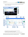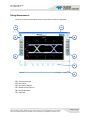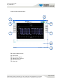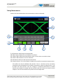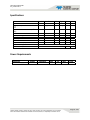
1
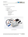
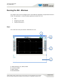
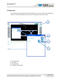
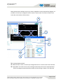
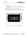
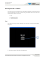
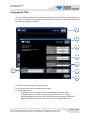
TDSO-090 USER GUIDE UG_0164PA0-0514 TDSO-090 User Guide Version 1.1 May, 2014 Software Covered in this Version Windows GUI V1.3 Labview GUI V10.03.14 TSDO IP Configurator V1.0 Teledyne Scientific Company reserves the right to make changes to its product specifications at any time without notice. The information furnished herein is believed to be accurate; however, no responsibility is assumed for its use. Page 1 of 22 TDSO-090 USER GUIDE UG_0164PA0-0514 General Safety Summary Review the following safety precautions to avoid injury and prevent damage to this product or any products connected to it. To avoid potential hazards, use this product only as specified. Only qualified personnel should perform service procedures. While using this product, you may need to access other parts of the system. Read the General Safety Summary in other system manuals for warnings and cautions related to operating the system. To Avoid Fire or Personal Injury Use Proper Power Cord. Use only the power cord specified for this product and certified for the country of use. Connect and Disconnect Properly. Do not connect or disconnect probes or test leads while they are connected to a voltage source. Observe All Terminal Ratings. To avoid fire or shock hazard, observe all ratings and markings on the product. Consult the product manual for further ratings information before making connections to the product. Do Not Operate With Covers or Panels Removed. Avoid Exposed Circuitry. Do not touch exposed connections and components when power is present. Do Not Operate in Wet/Damp Conditions. Do Not Operate in an Explosive Atmosphere. Keep Product Surfaces Clean and Dry. Symbols and Terms in this manual. These terms may appear in this manual: CAUTION. Identify conditions or practices that could result in damage to this product or other property. Teledyne Scientific Company reserves the right to make changes to its product specifications at any time without notice. The information furnished herein is believed to be accurate; however, no responsibility is assumed for its use. Page 2 of 22 TDSO-090 USER GUIDE UG_0164PA0-0514 Preface This is the user manual for the instrument. It covers the following information: Describes how to install its software Explains how to operate the instrument: how to control acquisition of, processing of, and input/output of information Lists the specifications of the instrument About This Manual This manual is composed of the following chapters: Getting Started shows you the how to configure and install your instrument. Operating Basics providing the required procedure to operate the instrument, including the software user interface. Description for all the performed measurements. Electrical Specifications. Teledyne Scientific Company reserves the right to make changes to its product specifications at any time without notice. The information furnished herein is believed to be accurate; however, no responsibility is assumed for its use. Page 3 of 22 TDSO-090 USER GUIDE UG_0164PA0-0514 Package Contents The TDSO‐090 box should contain the following: The main instrument. Micro USB cable. Cross‐over Ethernet cable. AC adapter. USB flash memory holding the following Software: o Microsoft .Net Framework. o TDSO Windows GUI. o TDSO Labview GUI. o TDSO USB driver. o TDSO IP configuration tool. o Windows API. Figure 1: Package Content Teledyne Scientific Company reserves the right to make changes to its product specifications at any time without notice. The information furnished herein is believed to be accurate; however, no responsibility is assumed for its use. Page 4 of 22 TDSO-090 USER GUIDE UG_0164PA0-0514 Minimum PC Requirements The minimum Windows PC properties for the TDSO application must meet the following specifications: Windows XP SP3 or greater. Minimum 1 GB RAM. 1 Ethernet card to establish connection with the device. 1 USB port for IP configuration. Pentium 4 processor 2.0 GHz or greater. .NET Framework 3.5 sp1. NOTE. Up to 32 TDSOs can be connect to one PC using the Windows GUI. Labview GUI is limited to one connection. Teledyne Scientific Company reserves the right to make changes to its product specifications at any time without notice. The information furnished herein is believed to be accurate; however, no responsibility is assumed for its use. Page 5 of 22 TDSO-090 USER GUIDE UG_0164PA0-0514 Installation This chapter covers installation of the instrument, addressing the following topics: Quick Start. How to connect the instrument and installing the USB driver. Configuring the IP address. Quick Start To use the TDSO under Windows XP, Windows 7 and Vista, it is important that the correct sequence is followed: Make sure you have the Microsoft .NET Framework 3.5. If not it is included in the USB flash memory. Install the Software from the USB flash memory. The GUI and the Configurator are the minimum requirement. Power the device using the included AC adapter. Connect the device to the PC using the USB cable. Install the USB driver. Configure the IP address using DSOConfig.exe. Connect the device to the network using the Ethernet cable (the connection can be through a router, switch, or directly to a PC). Run TDSO‐GUI.exe. Teledyne Scientific Company reserves the right to make changes to its product specifications at any time without notice. The information furnished herein is believed to be accurate; however, no responsibility is assumed for its use. Page 6 of 22 TDSO-090 USER GUIDE UG_0164PA0-0514 How to connect this instrument to the computer The TDSO has 2 connection ports: USB and Fast Ethernet. NOTE. The Ethernet connection is used for the measurements applications, and the USB connection is used only to configure the device IP Address. Install Software from the USB Flash Memory Run Setup.exe from the flash drive to install the software. If the PC does not have Microsoft .NET 3.5, install it. It is included in the USB flash memory. USB Driver Installation Power the device using the included AC adapter. Connect the device to the PC using the USB cable. When the PC tries to install the driver manually select the driver location. It is located in the USB Driver folder in the USB flash memory. Configuring the IP address The TDSO comes pre‐configured with an IP address of 192.168.0.100. You can change the IP address by following the steps below: Power the device using the included AC adapter. Connect the device to the PC using the USB cable. Run DSO‐Config The program will recognized the TDSO and will display its current configuration. Change the desired configuration and click the “W” button to configure the device. Exit the program and disconnect the USB cable. NOTE. The configuration values can also be refreshed by clicking on the status bar at the bottom of the DSO‐Config window. Teledyne Scientific Company reserves the right to make changes to its product specifications at any time without notice. The information furnished herein is believed to be accurate; however, no responsibility is assumed for its use. Page 7 of 22 TDSO-090 USER GUIDE UG_0164PA0-0514 Running the GUI - Windows This chapter covers how to configure and run the TDSO‐GUI application to capture data from the TDSO. The application is a native windows application and uses .NET 3.5. Start. Configuring the TDSO. Taking measurements. Start This is the first screen you see when TDSO‐GUI.exe is run. 1 2 3 4 1 ‐ Mode Selection: Eye, Pattern, Mask. 2 ‐ Connect to TDSO. 3 ‐ Main window. 4 ‐ Results Window. Teledyne Scientific Company reserves the right to make changes to its product specifications at any time without notice. The information furnished herein is believed to be accurate; however, no responsibility is assumed for its use. Page 8 of 22 TDSO-090 USER GUIDE UG_0164PA0-0514 Configuration The TDSO needs to be configured and connected before it can be used. When the configuration button is clicked a window opens where you can add, configure and remove a TDSO. 5 6 7 8 5 ‐ Connect button. 6 ‐ Add TDSO. 7 ‐ Remove TDSO. 8 ‐ Configure existing TDSO. Teledyne Scientific Company reserves the right to make changes to its product specifications at any time without notice. The information furnished herein is believed to be accurate; however, no responsibility is assumed for its use. Page 9 of 22 TDSO-090 USER GUIDE UG_0164PA0-0514 When a TDSO is added or when the configuration button of an existing TDSO is clicked the configuration window appears. 9 10 12 11 13 14 15 16 17 18 19 21 20 9 ‐ Name: TDSO name (up to 32 TDSOs can be connected simultaneously). 10 ‐ IP Address: Factory configured as 192.168.0.100. 11‐ Recall configuration from the TDSO (IP Address need to be entered before recall). Teledyne Scientific Company reserves the right to make changes to its product specifications at any time without notice. The information furnished herein is believed to be accurate; however, no responsibility is assumed for its use. Page 10 of 22 TDSO-090 USER GUIDE UG_0164PA0-0514 12 ‐ Connect button: Connect to TDSO and load the current configuration. 13 ‐ Line Rate: Incoming data stream speed in Gbps. 14 ‐ Input Path: Data input connection (single ended or differential). 15 ‐ Reference Clock: Needs to be set to External for the TDSO‐090. NOTE. The CLK input is required for the TDSO operation. The Data Input (INP, INN) can be used in single ended or differential mode. Using the TDSO in differential input mode will give better results. 16 ‐ Number of Packets: Number of points for the sample size in 1,000 per packet. 17 ‐ Advance options: Wander Confiscation. PTB: Internal Precision Time Base for clock generation. Wander (Wander Confiscation) enables or disables the Time Base Wander Correction for a measurement. Small variations in the TDSO internal reference time base appear as low‐ frequency jitter (wander) in the acquired signal. 18 ‐ NRZ Threshold: Range used for the rise/fall measurements. 19 ‐ External Reference Clock: Can be set as a frequency or a division of the data rate. The ideal reference clock should be between 100MHz and 400MHz. 20 ‐ Pattern Length: Default is 127 bits (PRBS 7). 21 ‐ File Control: Open or save configuration file. Teledyne Scientific Company reserves the right to make changes to its product specifications at any time without notice. The information furnished herein is believed to be accurate; however, no responsibility is assumed for its use. Page 11 of 22 TDSO-090 USER GUIDE UG_0164PA0-0514 Taking Measurements Below is the main window where the eye measurement results are displayed. 23 22 24 24 25 25 26 27 22 ‐ Eye Mode selected. 23 ‐ Run Button. 24 ‐ Run Control Options. 25 ‐ Measurement Selection. 26 ‐ Results Windows. 27 ‐ Status Bar. Teledyne Scientific Company reserves the right to make changes to its product specifications at any time without notice. The information furnished herein is believed to be accurate; however, no responsibility is assumed for its use. Page 12 of 22 TDSO-090 USER GUIDE UG_0164PA0-0514 Pattern measurements window. 28 29 30 30 31 31 32 33 28 ‐ Pattern Mode selected. 29 ‐ Run Button. 30 ‐ Run Control Options. 31 ‐ Measurement Selection. 32 ‐ Results Windows. 33 ‐ Status Bar. Teledyne Scientific Company reserves the right to make changes to its product specifications at any time without notice. The information furnished herein is believed to be accurate; however, no responsibility is assumed for its use. Page 13 of 22 TDSO-090 USER GUIDE UG_0164PA0-0514 Mask measurements window. Here an eye mask is applied on the last captured eye diagram. It is possible to choose a pre‐configured mask or create a custom mask. The result is shown in the status bar at the bottom of the window. 34 35 36 37 38 39 34 ‐ Eye Mask Mode selected. 35 ‐ Mask Selection: There are several pre‐configured masks or a custom mask can be selected. 36 ‐ Apply Mask: The result can be seen in the figure below were the mask is superimposed to the last eye diagram captured and the number of points failing is shown in the status bar. Teledyne Scientific Company reserves the right to make changes to its product specifications at any time without notice. The information furnished herein is believed to be accurate; however, no responsibility is assumed for its use. Page 14 of 22 TDSO-090 USER GUIDE UG_0164PA0-0514 37 ‐ Mask Margin. Mask Margin Percentage: This percentage is applied in the configured mask to increasing its size. Find Mask Margin: Finds how much the mask can be increased before it gets failing points. 38 ‐ Custom Mask Options: These sections configure the shape of the mask. 39 ‐ Custom Mask Values. When create a custom mask those values define the mask, when a pre‐defined mask is selected those values are filled with the values for the mask selected. Teledyne Scientific Company reserves the right to make changes to its product specifications at any time without notice. The information furnished herein is believed to be accurate; however, no responsibility is assumed for its use. Page 15 of 22 TDSO-090 USER GUIDE UG_0164PA0-0514 Running the GUI - LabView This chapter covers how to configure and run the TDSO‐GUI application to capture data from the TDSO. The application was written in LabView using the Windows API to control the device. LabView 2011 is needed to run this GUI. Start. Configuring the TDSO. Taking measurements. Start This is the first screen you see when TDSO‐GUI is run. Here there is a selection of which TDSO is being used. 1 1 ‐ TDSO Selection button: TDSO‐050 or TDSO‐090 options. Teledyne Scientific Company reserves the right to make changes to its product specifications at any time without notice. The information furnished herein is believed to be accurate; however, no responsibility is assumed for its use. Page 16 of 22 TDSO-090 USER GUIDE UG_0164PA0-0514 Configuring the TDSO After the selection windows the measurement window is shown. Before any measurements can be taken it is necessary that the TDSO is configured and a connection is made. The SETUP button will open the configuration window. 2 3 4 5 6 9 7 8 2 ‐ SETUP button: Will display the setup window. 3 ‐ EXIT button: Return to the measurements window. 4 ‐ SETUP Option Block: IP ADDRESS: Input the IP address of the TDSO (default is 192.168.0.100). PATTERN LENGTH: Test pattern length for the test (default is 127 – PRBS7). NRZ THRESHOLD: Range used for the rise/fall measurements (default is 20%‐80%). SAMPLE SIZE: Number of points for the sample size in 1,000s (default is 64). Teledyne Scientific Company reserves the right to make changes to its product specifications at any time without notice. The information furnished herein is believed to be accurate; however, no responsibility is assumed for its use. Page 17 of 22 TDSO-090 USER GUIDE UG_0164PA0-0514 5 ‐ DATA RATE CONFIGURATION Option Block: DATA RATE: Incoming data stream speed in Gbps (default is 10.3125). FILE INDEX: Configuration file to be used for the internal TDSO clock setup (default is 0). The File Index is used to configure the internal TDSO clock generation. Each configuration used (Data Rate / Reference Clock) needs a separated configuration file. If the configuration file does not exists it is created the first time the specific configuration is run (it will take a couple of minutes to generate the configuration file). Multiple files can be generated, hence the index. It selects the desired configuration file. If the index is ‐1 the TDSO will run with the last used configuration file. All the pre‐set data rates in the DATA RATE drop down already have an index 0 configuration file installed. The DATA RATE DIVIDER for the reference clock for those pre‐installed files is as follows: 1.25Gbps to 1.5Gbps – 4 1.969Gbps to 6.25Gbps – 16 8.5Gbps to 20Gbps – 64 6 ‐ CLOCK CONFIGURATION Option Block: CLOCK SOURCE: Fixed in the TDSO‐090 (External). DATA RATE DIVIDER: The clock should be a fraction of the data rate (default is 64). The ideal reference clock should be between 100MHz and 400MHz. NOTE. The CLK input is required for the TDSO operation. The Data Input (INP, INN) can be used in single ended or differential mode. Using the TDSO in differential input mode will give better results. 7 ‐ ADVANCED Option Block: WANDER: Wander Confiscation (default is OFF). PTB: Internal Precision Time Base for clock generation (default is ON). WANDER (Wander Confiscation) enables or disables the Time Base Wander Correction for a measurement. Small variations in the TDSO internal reference time base appear as low‐ frequency jitter (wander) in the acquired signal. 8 ‐ CONNECT button: Connect to TDSO and load the current configuration. 9 – DATA WRITE Option Block: FOLDER: Location of the folder where the data is to be saved. FILE NAME: File name to be used for the saved data. Teledyne Scientific Company reserves the right to make changes to its product specifications at any time without notice. The information furnished herein is believed to be accurate; however, no responsibility is assumed for its use. Page 18 of 22 TDSO-090 USER GUIDE UG_0164PA0-0514 Taking Measurements Below is the main window where the measurements results are displayed. 12 13 2 10 11 14 15 16 17 2 ‐ SETUP button: Will display the setup window. 10 ‐ Main Display: Display the eye and pattern waveforms. 11 ‐ Results Table: Shows the measurements results. Current values or statistical values. 12 ‐ Results Table Selection: Current or Statistical. 13 ‐ RUN button: Will start and stop the measurements. 14 ‐ Sample Counter: This is the number of samples to be used for the statistical measurements. This reflects the way the Windows API operates. There is a function call for the display (waveform) and a separated one for the data measurements. When the COUNT value is 1 all the data is the same (current, max, min, average). If a statistical measurement is needed COUNT value should be increased and the statistical table will reflect the results for those samples. In this case the waveform only reflects the last sample taken. Teledyne Scientific Company reserves the right to make changes to its product specifications at any time without notice. The information furnished herein is believed to be accurate; however, no responsibility is assumed for its use. Page 19 of 22 TDSO-090 USER GUIDE UG_0164PA0-0514 15 ‐ EYE / PATTERN button: Display the eye or pattern waveform. 16 ‐ File Save Option Block: SAVE: Button to start and stop saving. Works only when in RUN mode. SCREEN: Save a screen snapshot. DATA: Save the raw data. Can be used to re‐construct the waveform. 17 ‐ Waveform Display Values: Shows the vertical and horizontal scales. Teledyne Scientific Company reserves the right to make changes to its product specifications at any time without notice. The information furnished herein is believed to be accurate; however, no responsibility is assumed for its use. Page 20 of 22 TDSO-090 USER GUIDE UG_0164PA0-0514 Specifications Parameter Symbol Input Bandwidth Input Amplitude Conditions Min Single Ended Input Rise Time and Fall Time (20% to 80%) Vertical Resolution Clock Input Range Clock Input Amplitude Input Impedance Intrinsic Jitter Amplitude Error (rms) Data Format supported PRBS Pattern Capture Typ Max Units 25GHz 1.0Vpp GHz V <20 pS 12 710 1.5 1pS bits MHz VPP Ώ rms mV rms tRT, tFT 50 0.25 Z 50 5 NRZ PN11 Power Requirements Parameter External + 5V supply Symbol Conditions PWR External Min Typ 1.5 Max Units A Teledyne Scientific Company reserves the right to make changes to its product specifications at any time without notice. The information furnished herein is believed to be accurate; however, no responsibility is assumed for its use. Page 21 of 22 TDSO-090 USER GUIDE UG_0164PA0-0514 Warranty LIMITED WARRANTY Seller warrants that the all work will be performed in a professional and workmanlike manner consistent with industry standards. THESE EXPRESS WARRANTIES, INCLUDING THE REMEDIES SET FORTH HEREIN, ARE EXCLUSIVE AND ARE IN LIEU OF ANY AND ALL OTHER WARRANTIES, EXPRESS OR IMPLIED. NO WARRANTY OF MERCHANTABILITY OR FITNESS FOR A PARTICULAR PURPOSE IS INTENDED IN THE CASE OF GOODS OTHER THAN THOSE OF SELLER’S OWN MANUFACTURE, SELLER MAKES NO WARRATIES, EXPRESS, STATUTORY, OR IMPLIED. THESE EXPRESS WARRANTIES, INCLUDING THE REMEDIES SET FORTH HEREIN, ARE EXCLUSIVE AND ARE IN LIEU OF ANY AND ALL OTHER WARRANTIES, EXPRESS OR IMPLIED. NO WARRANTY OF MERCHANTABILITY OR FITNESS FOR A PARTICULAR PURPOSE IS INTENDED OR GIVEN. IN THE CASE OF GOODS OTHER THAN THOSE OF SELLER’S OWN MANUFACTURE, SELLER MAKES NO WARRANTIES, EXPRESS, STATUTORY, OR IMPLIED. RETURN AUTHORIZATIONS Buyer’s return of defective Goods to Seller is subject to Seller’s then current return authorization procedures. Buyer shall promptly notify Seller of any nonconformance or defects in Goods, and provide Seller a reasonable opportunity to inspect such Goods. Goods shall not be returned without Seller's prior authorization, as evidenced by a Return Material Authorization (RMA) number issued by Seller. Once a RMA number is obtained, Buyer shall return Goods transportation and insurance prepaid in accordance with instructions issued by Seller. Failure to follow Seller’s return authorization procedures may result in lost Goods, delays, additional service, restocking charges, warranty denial, or refusal of a return shipment. The RMA number must appear on the shipping label and all paperwork associated with the return. Buyer shall identify the model or part number, description, and serial number, if applicable, for each of the Goods returned along with an explanation of the nonconformance or defect. Issuance of a RMA number by Seller does not necessarily mean Seller agrees that returned Goods are defective or covered under warranty, or that Goods will be repaired or replaced at no cost to Buyer. If any Goods returned by Buyer are found to not be defective, Buyer shall be so notified and such Goods shall be repaired, replaced, or returned to Buyer at Buyer’s option and expense. Such repair or replacement shall not be performed until and unless Buyer issues an Order to Seller authorizing such repair or replacement at Seller’s then-current repair or replacement price. In addition, Seller may charge Buyer for any testing or inspection costs. In no event shall Seller retain or store returned Goods for more than six (6) months. Goods repaired or replaced under warranty shall be returned to Buyer at Seller’s expense. Teledyne Scientific Company reserves the right to make changes to its product specifications at any time without notice. The information furnished herein is believed to be accurate; however, no responsibility is assumed for its use. Page 22 of 22