1
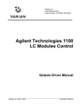
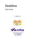
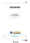
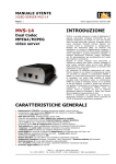
User Manual PF3DSuite
Photonfocus AG
User Manual PF3DSuite
Photonfocus AG
$Revision: 3113 $
Copyright © 2012, Photonfocus AG
All information provided in this manual is believed to be accurate and reliable. No responsibility is assumed by Photonfocus AG for its use.
Photonfocus AG reserves the right to make changes to this information without notice.
Reproduction of this manual in whole or in part, by any means, is prohibited without prior permission having been obtained from Photonfocus
AG.
Table of Contents
1. Preface .................................................................................................................... 1
About Photonfocus ................................................................................................ 1
Contact ............................................................................................................... 1
Sales Offices ........................................................................................................ 1
Further information ............................................................................................... 1
Legend ................................................................................................................ 2
2. Installation Procedure ................................................................................................. 3
Requirements ....................................................................................................... 3
Hardware Requirements ................................................................................. 3
GigE Installation ................................................................................................... 4
Hardware Installation ..................................................................................... 4
Software Installation ...................................................................................... 5
Network Adapter Configuration ....................................................................... 6
Network Adapter Configuration for Pleora eBUS SDK ....................................... 10
Camera Link ...................................................................................................... 11
PF3DSuite Installation .......................................................................................... 11
Structure of the Installation Directory ............................................................. 12
3. PF3DSuite Tool ...................................................................................................... 13
Introduction ........................................................................................................ 13
Graphical User Interface ....................................................................................... 13
Starting the Live Image ........................................................................................ 15
Camera selection ......................................................................................... 16
Range Map ................................................................................................ 18
Save and Load Configuration Files ................................................................. 18
Camera Configuration .......................................................................................... 18
Adquisition Modes ...................................................................................... 19
Set up the Region of Interest ......................................................................... 21
Dual Peak (MV1-D2048X1088-3D03 only) ...................................................... 22
Frame Contrast and Live Image Visualization ........................................................... 24
Image Normalization .................................................................................... 25
Zooming Live Image ................................................................................... 25
Histogram .................................................................................................. 25
3D Acquisition ................................................................................................... 26
General Overview ....................................................................................... 26
3D Settings ................................................................................................ 28
3D Visualization ......................................................................................... 29
Visualization of the Laser Profile ................................................................... 31
Transformation Parameters Estimation ............................................................ 31
SDK ................................................................................................................. 32
SAL3D ...................................................................................................... 32
eBUS SDK ................................................................................................ 32
HALCON extension .................................................................................... 33
4. Warranty ................................................................................................................ 34
Warranty Terms .................................................................................................. 34
Warranty Claim .................................................................................................. 34
5. References .............................................................................................................. 35
A. Revision History ..................................................................................................... 36
iii
List of Figures
2.1. Rear view of the GigE camera MV1-D1312(IE)-40-G2 with power supply and I/O
connector, Ethernet jack (RJ45) and status LED ................................................................. 5
2.2. eBUS Driver Installation Tool ................................................................................... 6
2.3. Local Area Connection Properties .............................................................................. 7
2.4. TCP/IP Properties ................................................................................................... 8
2.5. Advanced Network Adapter Properties ....................................................................... 9
2.6. Windows Firewall Configuration .............................................................................. 10
2.7. Local Area Connection Properties ............................................................................ 11
Setup PF3DSuite ......................................................................................................... 12
3.1. PF3DSuite Main Window ....................................................................................... 14
3.2. Acquisition configuration menu ............................................................................... 16
3.3. GEV Device Control Dialog ................................................................................... 19
3.4. PF3DSuite 2D&3D Acquisition mode ....................................................................... 20
3.5. PF3DSuite 3Donly Acquisition mode ........................................................................ 21
3.6. PF3DSuite - Setup Mode. Selected ROI is displayed within the green rectangle. ................ 22
3.7. PF3DSuite - Main Frame with dual peak in 2D and 3D mode. ....................................... 23
3.8. PF3DSuite - Main Frame with dual peak in 2D and 3D mode. ....................................... 24
3.9. PF3DSuite - Main Frame with dual peak in 2D and 3D mode. ....................................... 24
3.10. Histogram Viewer ............................................................................................... 25
3.11. Example of the projection of a laser over an object. ................................................... 26
3.12. Generation of the range map from profiles: a) Coordinates of the peak position in the
current frame, b) Current profile in (u,v,g) coordinates, and c) Set of consecutive profiles .......... 27
3.13. Example of an acquired range map ......................................................................... 27
3.14. Metric transformation: from range map coordinates to 3D coordinates ........................... 28
3.15. Example of the 3D representation of the range map ................................................... 28
3.16. Range Map viewer ............................................................................................... 30
3.17. 3D Viewer ......................................................................................................... 31
iv
List of Tables
1.1. Photonfocus Contact ................................................................................................ 1
v
Chapter 1. Preface
About Photonfocus
The Swiss company Photonfocus is one of the leading specialists in the development of CMOS
image sensors and corresponding industrial cameras for machine vision, security & surveillance and
automotive markets.
Photonfocus is dedicated to making the latest generation of CMOS technology commercially available.
Active Pixel Sensor (APS) and global shutter technologies enable high speed and high dynamic range
(120 dB) applications, while avoiding disadvantages like image lag, blooming and smear.
Photonfocus has proven that the image quality of modern CMOS sensors is now appropriate for
demanding applications. Photonfocus' product range is complemented by custom design solutions in
the area of camera electronics and CMOS image sensors.
Photonfocus is ISO 9001 certified. All products are produced with the latest techniques in order to
ensure the highest degree of quality.
Contact
Photonfocus AG, Bahnhofplatz 10, CH-8853 Lachen SZ, Switzerland
Table 1.1. Photonfocus Contact
Sales
Phone: +41 55 451 07 45
Email: [email protected]
Support
Phone: +41 55 451 01 37
Email:
[email protected]
Sales Offices
Photonfocus products are available through an extensive international distribution network and
through our key account managers. Details of the distributor nearest you and contacts to our key
account managers can be found at www.photonfocus.com [http://www.photonfocus.com].
Further information
Note
Photonfocus reserves the right to make changes to its products and documentation without
notice. Photonfocus products are neither intended nor certified for use in life support
systems or in other critical systems. The use of Photonfocus products in such applications
is prohibited.
Note
Photonfocus is a trademark and LinLog is a registered trademark of Photonfocus AG.
CameraLink and GigE Vision are a registered mark of the Automated Imaging Association.
Product and company names mentioned herein are trademarks or trade names of their
respective companies.
Note
Reproduction of this manual in whole or in part, by any means, is prohibited without prior
permission having been obtained from Photonfocus AG.
1
Preface
Note
Photonfocus can not be held responsible for any technical or typographical errors.
Legend
In this documentation the reader's attention is drawn to the following icons:
Note
Important note
Important
Alerts and additional information
Caution
Attention, critical warning
Tip
Notification, user guide
2
Chapter 2. Installation Procedure
The following software packages have to be installed:
• GigE installation (eBUS-SDK_...exe)
• PF3DSuite installation (PFInstaller_...exe)
Requirements
The PF3DSuite GUI is available for Windows operating systems. For Linux or QNX operating
systems, we provide the necessary libraries to control the camera on request, but there is no graphical
user interface available.
Important
If you require support for Linux or QNX operating systems, you may contact Photonfocus
[http://www.photonfocus.com/] for details of support conditions.
The PF3DSuite includes some examples for developers. In the SDK\examples directory you will find
some Visual C++ projects using the SAL3D library from AQSense.
In order to compile the examples, it is necessary to install the SAL3D library, which can be downloaded
for free from:
http://www.photonfocus.com/html/eng/support/software.php
The compatible version with the current PF3DSuite and SDK is the SAL3D 12.1.22.
Hardware Requirements
This version of PF3DSuite supports the following 3D cameras:
• MV-D1024E-3D01
prodId=41]
camera
• MV1-D1312-3D02-160-G2
products.php?prodId=103]
[http://www.photonfocus.com/html/eng/products/products.php?
camera
• MV1-D2048X1088-3D03-760-G2
products.php?prodId=104]
camera
[http://www.photonfocus.com/html/eng/products/
[http://www.photonfocus.com/html/eng/products/
This version of PF3DSuite is compatible with the following frame grabbers:
• SiliconSoftware MicroEnable4 [http://www.silicon-software.com/microenable4.html]
• DALSA X64 Xcelera-CL PX4 [http://mv.dalsa.com/Web/home.nsf/MainFrame/MainFrame?
OpenDocument&L_FS=Gb&C_FS=PgTopGb&T_FIG=pg&C_FIG=PgNavProductsGb&db_FID=products.nsf&T_F
OpenForm&L_FID=Gb]
• BitFlow Frame Grabbers [http://www.bitflow.com/index.php]
• File Frame Grabber
Please, contact the Support at Photonfocus or check the Photonfocus website [http://
www.photonfocus.com/] for more recent versions of the PF3DSuite and about the latest list of
compatible frame grabbers.
3
Installation Procedure
GigE Installation
The installation procedure goes as follows: first of all it is necessary to install the hardware, then the
software and finally to configure the network adapters. After that the user can install the PFRemote
and the PF3DSuite (see the section called “PF3DSuite Installation”).
Hardware Installation
The hardware installation that is required for this guide is described in this section.
The following hardware is required:
• PC with Microsoft Windows OS (XP, Vista, Windows 7)
• A Gigabit Ethernet network interface card (NIC) must be installed in the PC. The NIC should
support jumbo frames of at least 9014 bytes. In this guide the Intel PRO/1000 GT desktop adapter
is used. The descriptions in the following chapters assume that such a network interface card (NIC)
is installed. The latest drivers for this NIC must be installed.
• Photonfocus GigE camera.
• Suitable power supply for the camera (see in the camera manual for specification) which can be
ordered from your Photonfocus dealership.
• GigE cable of Cat 5E or 6
The following list describes the connection of the camera to the PC (see in the camera manual for
more information):
1. Remove the Photonfocus GigE camera from its packaging.
Please make sure the following items are included with your camera:
• Power supply connector
• Camera body cap
If any items are missing or damaged, please contact your dealership.
2. Connect the camera to the GigE interface of your PC with a GigE cable of Cat 5E or 6.
4
Installation Procedure
Figure 2.1. Rear view of the GigE camera MV1-D1312(IE)-40-G2 with power
supply and I/O connector, Ethernet jack (RJ45) and status LED
3. Connect a suitable power supply to the power plug. The pin out of the connector is shown in the
camera manual.
Caution
Check the correct supply voltage and polarity! Do not exceed the operating voltage range
of the camera.
Note
A suitable power supply can be ordered from your Photonfocus dealership.
4. Connect the power supply to the camera (see Figure 2.1, “Rear view of the GigE camera MV1D1312(IE)-40-G2 with power supply and I/O connector, Ethernet jack (RJ45) and status LED”).
Software Installation
This section describes the installation of the required software to accomplish the tasks described in
this chapter.
1. Install the latest drivers for your GigE network interface card.
2. Download the latest eBUS SDK installation file from the Photonfocus server.
Note
You can find the latest version of the eBUS SDK on the support (Software Download)
page at www.photonfocus.com [http://www.photonfocus.com].
3. Install the eBUS SDK software by double-clicking on the installation file. Please follow the
instructions of the installation wizard. A window might be displayed warning that the software has
not passed Windows Logo testing. You can safely ignore this warning and click on Continue
5
Installation Procedure
Anyway. If at the end of the installation you are asked to restart the computer, please click on Yes
to restart the computer before proceeding.
4. After the computer has been restarted, open the eBUS Driver Installation tool (Start -> All
Programs -> eBUS SDK -> Tools -> Driver Installation Tool) (see Figure 2.2,
“eBUS Driver Installation Tool”). If there is more than one Ethernet network card installed then
select the network card where your Photonfocus GigE camera is connected. In the Action dropdown list select Install eBUS Universal Pro Driver and start the installation by
clicking on the Install button. Close the eBUS Driver Installation Tool after the installation has
been completed. Please restart the computer if the program asks you to do so.
Figure 2.2. eBUS Driver Installation Tool
Network Adapter Configuration
This section describes recommended network adapter card (NIC) settings that enhance the
performance for GigEVision. Additional tool-specific settings are described in the tool chapter.
1. Open the Network Connections window (Control Panel -> Network and Internet
Connections -> Network Connections), right click on the name of the network adapter
where the Photonfocus camera is connected and select Properties from the drop down menu
that appears.
6
Installation Procedure
Figure 2.3. Local Area Connection Properties
2. By default, Photonfocus GigE Vision cameras are configured to obtain an IP address automatically.
For this quick start guide it is recommended to configure the network adapter to obtain an IP address
automatically. To do this, select Internet Protocol (TCP/IP) (see Figure 2.3, “Local Area
Connection Properties”), click the Properties button and select Obtain an IP address
automatically (see Figure 2.4, “TCP/IP Properties”).
7
Installation Procedure
Figure 2.4. TCP/IP Properties
3. Open again the Local Area Connection Properties window (see Figure 2.3, “Local
Area Connection Properties”) and click on the Configure button. In the window that appears
click on the Advanced tab and click on Jumbo Frames in the Settings list (see Figure 2.5,
“Advanced Network Adapter Properties”). The highest number gives the best performance. Some
tools however don't support the value 16128. For this guide it is recommended to select 9014
Bytes in the Value list.
8
Installation Procedure
Figure 2.5. Advanced Network Adapter Properties
4. No firewall should be active on the network adapter where the Photonfocus GigE camera is
connected. If the Windows Firewall is used then it can be switched off like this: Open the Windows
Firewall configuration (Start -> Control Panel -> Network and Internet
Connections -> Windows Firewall) and click on the Advanced tab. Uncheck the network
where your camera is connected in the Network Connection Settings (see Figure 2.6,
“Windows Firewall Configuration”).
9
Installation Procedure
Figure 2.6. Windows Firewall Configuration
Network Adapter Configuration for Pleora eBUS SDK
Open the Network Connections window (Control Panel -> Network and Internet
Connections -> Network Connections), right click on the name of the network adapter
where the Photonfocus camera is connected and select Properties from the drop down menu
that appears. A Properties window will open. Check the eBUS Universal Pro Driver (see
Figure 2.7, “Local Area Connection Properties”) for maximal performance. Recommended settings
for the Network Adapter Card are described in the section called “Network Adapter Configuration”.
10
Installation Procedure
Figure 2.7. Local Area Connection Properties
Camera Link
The support information for CamerLink grabbers is coming soon.
PF3DSuite Installation
The PF3DSuite is a graphical application intended to correctly configure and ease the evaluation of
the Photonfocus product range of 3D digital cameras. The latest release can be downloaded from
the support area of http://www.photonfocus.com [http://www.photonfocus.com/]. PF3DSuite does not
only allow to see the effects of the camera configuration parameters with live image, but it is also able
to show the 3D information acquired in real time.
Locate the PF3DSuite installer file in the folder "PF3DSuite" and start the setup wizard as shown in
Figure , “Setup PF3DSuite”.
11
Installation Procedure
Figure . Setup PF3DSuite
The PF3DSuite package installs several files into the Microsoft Windows system. Although the user
may change the installation directory when running the MSI installer, by default it proposes the
recommended path C:\Program Files\Photonfocus\PF3DSuite2\. It is also recommended to use the
default settings during installation.
Structure of the Installation Directory
The SDK included with the PF3DSuite is a C++ software library entitled "SAL3D".
• bin - The main PF3DSuite binary, DLLs from the SAL3D, and precompiled executables of the
examples distributed with the SAL3D SDK. This folder also includes Frame Grabber Driver binary
files (*.fgd). You need these files to use the PF3DSuite, in order to grab frame objects easily. Each
FGD file supports one frame grabber device for 3D cameras with Cameralink interface.
• configfiles - The configuration files for the different frame grabbers, in order to set up the window
size, number of taps, pixel depth and other features.
• SDK\doc - The SAL3D SDK documentation in html. Open the index.html to start.
• SDK\examples - Visual C++ example projects using the Photonfocus camera configuration library.
• SDK\include - Path to be added to the INCLUDE_PATH parameter of your compiler. This directory
contains the C++ declarations in SAL3D, the internal declarations for the C functions and structures
used in the DLLs, and the Photonfocus camera configuration API declarations (pflib).
• SDK\lib - Path to be added to the LIBRARY_PATH parameter of your linker. These files will allow
the user to link his program to the SAL3D and Photonfocus DLLs.
12
Chapter 3. PF3DSuite Tool
Introduction
PF3DSuite is a graphical user interface (GUI) under Window OS intended to configure and ease the
evaluation of the Photonfocus [http://www.photonfocus.com/] product range of 3D digital cameras.
PF3DSuite provides the tools to see the effects of the camera configuration parameters within the live
image, and displays the 3D information acquired in real time.
With PF3DSuite you will be able to:
• Acquire and display live images.
• Configure the parameters of the 3D camera.
• View live images captured from the camera.
• View the results of the 3D acquisition settings.
Graphical User Interface
PF3DSuite consists of a main window, several secondary windows, and some configuration dialogs.
The main window displays the frame acquired by the camera. Additional windows display further
information of the PF3DSuite - the histogram window of the captured frame, the range map window,
the surface window, and the zoom window. The configuration dialogs let the user change the
acquisition (see the section called “Starting the Live Image”) and camera parameters (see the section
called “Camera Configuration”). The status bar displays the frame rate (number of frames successfully
acquired per second). This is the real number of frames processed, although the user may notice a
slower image refresh in the main window.
The main window displays a recently acquired camera frame. A toolbar contains buttons for the most
common actions regarding visualization and acquisition. These buttons are described in the following
figure. In addition to the toolbar, two vertical sliders to the left of the main window, allow to modify
the contrast of the frame displayed in the main window and in the zoom window (see the section called
“Image Normalization” for more information).
13
PF3DSuite Tool
Figure 3.1. PF3DSuite Main Window
Open the grabbing configuration dialog (see the section called “Starting the Live Image”).
Start grabbing with the current configuration.
Stop grabbing.
Activate/deactivate the ROI set up mode.
Open the histogram window.
Open the range map window.
Open the 3D viewer window.
Open the width map window.
Open the quality map window.
Open the line scan window.
Zoom in button.
Zoom out button.
Select the visualization mode (see the section called “Adquisition Modes”).
Select the number of laser peaks.
Sliders for the normalization of the frame.
In addition to the acquisition mode, PF3DSuite GUI provides the set up mode. This mode allows to
configure the camera parameters before starting the acquisition; the main window displays the camera
frame in full resolution, and a rectangular area shows the camera ROI, so the user is able to see which
area of the scene will be acquired, once the set up mode is quit and the acquisition mode is activated.
The user can switch between modes by either using the Camera → Set up Region of Interest menu
option or by applying the corresponding toolbar button (for more information about setting up the ROI
see the section called “Set up the Region of Interest”).
Before working in the set up mode, the frame grabber must be configured (see the section called
“Starting the Live Image”).
14
PF3DSuite Tool
Warning
While grabbing in acquisition mode, the program configures the frame grabber according to
the camera ROI found at the start of the image acquisition. Modification of the ROI while
grabbing can lead to wrong acquisitions.
Starting the Live Image
The acquisition configuration in PF3DSuite allows to select the appropriate frame grabber and to
communicate with the camera.
In order to configure the live image acquisition and to start the acquisition, the user must open the
Grab Parameters dialog by selecting Grabber → Config & Grab... from the menu bar and specify
the type of camera being used (see the section called “Starting the Live Image”). Three options are
available: a camera through a Cameralink Grabber, a GigE camera or a frame (File) already stored.
The application maintains the last accepted values of this dialog, and after the first grabbing, the user
can directly start the acquisition without any dialog using the Grabber → Grab... menu option or the
corresponding toolbar button. The acquisition can be stopped with the Grabber → Freeze menu option
or via the corresponding toolbar button.
15
PF3DSuite Tool
Figure 3.2. Acquisition configuration menu
To analyze a frame (File) already stored. The user must specify the size of the frame.
When using a Cameralink frame grabber, the user must select the serial port where the camera
is connected in the list of serial ports, next to the checkbox "Cameralink".
To select a GigE Camera.
Path of the frame grabber configuration file, specific for each frame grabber. The user has to
generate this configuration file, since it will be required for the follow up steps of the setup
process.
If no new frame is delivered by the camera within a time intervall that exceeds the specified time
out, the current range map is ended.
Limit of profiles per range map (see the section called “3D Acquisition”).
Transformation factors to modify the 3D proportions obtained from a range map (see the section
called “3D Acquisition”).
Camera selection
The PF3DSuite supports a number of pre-selected frame grabbers, with the specific driver code for
the pre-selected frame grabbers stored in external files. These drivers require the software of the
16
PF3DSuite Tool
frame grabber vendor (Windows drivers and libraries) to be installed prior to the installation of the
PF3DSuite. The default installation path for the drivers needed in the dialog is C:\Program Files
\Photonfocus\PF3DSuite\bin.
When using a Cameralink frame grabber, the application communicates with the camera delivering the
frames, and the camera parameters needed for proper acquisition can be set. For that, you need to select
the port from the list of serial ports, to which the camera is connected to. Select next to "Cameralink"
in the acquisition configuration menu. Remember, that if you want to modify the configuration of any
camera (not related to the Region of Interest), the program will ask again for the port of that camera
(see the section called “Camera Configuration”).
When using the File Frame Grabber to display stored image files, the size of the images must be
selected accordingly in order to display the stored images within a top-left subimage. The width and
the height of the images have to be entered in the edit control labeled "Use Frame Size".
In the case of a Cameralink frame grabber, you must also enter the path for a frame grabber
configuration file by clicking on the "Choose config. file" button. This file is specific for each frame
grabber, and the user has to create it using the proper software delivered by the frame grabber vendor.
This file provides the information for the acquisition system of the user, namely the port, the size of
the grabbed frames, the pixel data format, and other configuration parameters.
In order to connect a GigE camera, you can select a configuration file for the camera by clicking
on the "Choose config. file" button. This file can be created, for instance, with the GEVPlayer. You
only need to connect the camera, set the desired properties and store the configuration into a PureGev
Configuration File (with pvcfg extension). You can also use a txt file like the one provided in the
\PF3DSuite2\configfiles folder. If the camera it is already configured or you want to configure it using
the PF3DSutie, it can be connected also specifiying the IP or MAC address directly. In the "Driver
config." textbox you must enter the addresses in the following way, for instance, "ip=192.168.1.203"
or "mac=00-11-1c-f5-a0-d3". But the camera can be also selected manualy by leaving the "Driver
config." textbox blank. In that case, once you click in the "OK" button, a new window will appear,
allowing you to select any camera connected in your network.
During the acquisition of the 3D data (see the section called “3D Settings”) the timeout parameter
defines the maximum time allowed between two consecutive frames. If no new frame is delivered by
the camera for a time exceeding the defined time out, the current range map is ended. Any subsequent
frames will be displayed in a new range map. The time out condition is useful in acquisition systems
where the camera is working in trigger mode. The camera captures a frame for each pulse of the trigger
signal. When no pulses are received, the camera does not send frames any more and thus the range
map grabbing stops properly due to the time out condition.
Besides the regular frame grabber drivers that come with PF3DSuite (see the section called
“Requirements” for a list of frame grabbers drivers), PF3DSuite is also equipped with a special driver
called File Frame Grabber. This driver uses a list of stored image files and simulates an acquisition
process. The File Frame Grabber driver is useful for debugging purposes.
The remaining control tools of the "Range Map" belong to the topic 3D acquisition and will be
explained in the section called “3D Acquisition”.
Once all parameters have been set to start the live acquisition of images by the camera, press OK. If
you have selected to use the physical frame grabber, you may get asked by the frame grabber to enter
the frame grabber configuration file. If you have selected to use the File frame grabber, the PF3DSuite
will ask for the list of stored images, that shall get displayed as frames.
The user can save the shown frame, that was recently acquired. To save a selected frame, the
acquisition must be stopped. Select the File → Save Frame... menu option, which opens the file save
dialog. The user must choose a file name before saving the selected frame to a file in the desired folder.
A new dialog appears immediately afterwards to ask, whether additional peak information shall also
be saved. This peak information consists of 8 colums with pixel information, that describe the peak
information of the previously saved frame, namely the position, the width and the quality of the peak.
17
PF3DSuite Tool
It is also possible to save only the peak position of the last frame acquired using the File → Save Peak
Positions... menu option. In this case the positions of the peak will be stored as numbers in plain text.
Note, that the application does not allow to save any currently shown peak values while the application
is acquiring frames.
Range Map
The range map settings influence how range maps are displayed by the PF3DSuite. The size of the
displayed range maps can be defined in two ways:
1. Time out and
2. Number of profiles.
The Timeout (configured in the previous section) defines the maximum time allowed between two
consecutive frames. If a new frame is delivered by the camera for a time exceeding the defined time
out, the current range map is ended. Subsequent frames will be displayed in a new range map. The
time out condition may help in acquisition systems where the camera is working in trigger mode. The
camera captures a frame for each pulse of the trigger signal. When no pulses are received, the camera
does not send any frame, so the range map grabbing stops properly due to the time out condition.
The maximum number of profiles (Max. Profiles) defines the maximum size of any captured range
map. Once the range map is composed of the pre-selected amount of profiles, the application ends the
range map grabbing. Since both conditions are always used, each range map acquired ends if at least
one of both conditions is fulfilled.
In addition to the conditions explained above, the grabbing dialog allows the user to specify the
Transformation Factors U, V and G to get a metric approximation of the surfaces. These parameters
can also be modified during the visualization of the surface with the command Range Map - Change
3D factors... from the menu in the 3D Viewer window. The user is referred to the the section called
“Transformation Parameters Estimation” called “Transformation Parameters Estimation” for more
information about these factors.
Save and Load Configuration Files
Although the grabbing configuration parameters are stored in the registry, the user also can select
to save or to load the grabbing configuration in INI files. The INI files, in addition to the
grabbing parameters, contain all configuration parameters of the camera. In order to save the current
configuration, select the File → Save Configuration ... menu option (Note, that this option is not
available when the set up mode is selected). In order to get the camera parameters of interest,
PF3DSuite will present a list of serial ports to select to which port the camera is connected to. After
selecting the corresponding port, PF3DSuite will open a new dialog asking for the INI file path.
To load an INI configuration file, the user has to select the File → Load Configuration ... menu option
(Note, that this option is not available when the set up mode is selected). In order to set the camera
parameters to the correct camera, PF3DSuite will present a list of serial ports to select, to which port
the camera is connected to. After selecting the corresponding port, PF3DSuite will open a new dialog
asking for the INI file.
Camera Configuration
In order to change the configuration parameters of the camera, you must select inside the Camera
menu which camera/grabber you are using (CameraLink or GigE Vision). For the Cameralink grabber,
PF3DSuite will present a list of serial ports for choosing the camera, similar to the Grab Parameters
dialog (see Figure 3.2, “Acquisition configuration menu”). Double click on the serial port in order to
configure the camera. Please consult your camera manual for more information about the configuration
parameters that can be selected in this dialog.
18
PF3DSuite Tool
For the GigE Vision cameras, there are 3 different configuration dialogs: Device control,
Communication control and Stream control.
The user can configure several camera properties in order to set the exposure, trigger, gain, size of
the window, etc. Regarding the 3D adquisition, the user must configure the PeakDetector Threshold.
The raw image data is first processed by the threshold pre-filter before being analyzed by the Peak
Detector algorithm. All grey level values in the raw image data will be set to 0, if the grey value
undergoes a given threshold value.
Note
The raw image data and the threshold values are 12 bit values (maximum 4095).
Figure 3.3. GEV Device Control Dialog
Adquisition Modes
The following modes can be selected:
• 2D Mode: In the 2D mode laser line detection is turned off and the camera is sending raw image
data to the frame grabber, which can then be further processed on the frame grabber or by an image
processing software tool. No additional 3D information is transferred with the raw image data when
using the 2D mode. This mode serves as a preview mode in the setup and debugging phase.
19
PF3DSuite Tool
• 2D and 3D Mode: In this mode laser line detection is turned on and the camera sends the raw
image data including the necessary 3D information to the frame grabber. The raw image containing
the laser line is analyzed by the Peak Detector in the camera's FPGA. This 3D information is then
attached to the 2D raw image. In the PF3DSuite, the detected laser line is shown as a coloured line
in the 2D image. This mode serves as a preview mode in the setup and debugging phase of the
triangulation system.
• 3D Mode: Laser line detection is turned on and only the 3D data calculated by the Peak Detector
algorithm in the camera plus an additional image row is transmitted. The scan rate of this mode is
considerably faster than the 2D&3D mode.
Note
The 3Donly mode must be used to achieve the highest scan rate.
To acquire a range map, the user should ensure that the camera is either set to the 2D/3D mode or set to
the 3D mode. Once all the setup has been done as described above, the 3D system is ready for the first
3D measurement task. To start the 3D measurement press the toolbar button Grab or select the Grabber
Grab command from the menu. Figure 3.4, “PF3DSuite 2D&3D Acquisition mode” shows the live
image while PF3DSuite is in acquisition mode. Please consider that in case the camera is configured
in trigger mode a live image will only be visible if the camera receives a suitable external trigger.
Figure 3.4. PF3DSuite 2D&3D Acquisition mode
20
PF3DSuite Tool
Figure 3.5. PF3DSuite 3Donly Acquisition mode
Set up the Region of Interest
Although the ROI of the camera can be modified using the camera dialog, the user can also select the
ROI using the mouse. To do this, the user must activate the set up mode by the Camera → Region of
interest menu option (or by clicking the corresponding toolbar button Figure 3.1, “PF3DSuite Main
Window”). While in this mode, the camera ROI is set to the full resolution, the trigger is set to
Free Running, and the acquisition mode is set to 2D/3D, in order to make the ROI set up operation
comfortable.
The user can select the ROI by drawing a rectangle over the frame. To draw the rectangle, the user must
drag the mouse diagonally and release the mouse button to set the rectangle. After the ROI selection,
the user has to deactivate the Set up mode, in order to get the selected ROI applied. Leaving the set
up mode the camera is programmed according to the previously used dialog settings.
21
PF3DSuite Tool
Figure 3.6. PF3DSuite - Setup Mode. Selected ROI is displayed within the green
rectangle.
Note
For the width and the x-value of the ROI a few restrictions exist (see camera manual for
more details on ROI restrictions). When deactivating the set up mode, the GUI automatically
reconfigures the selected values nearest to the allowed values of the camera. The rectangle
is redrawn to show the final setting of the ROI, and the user is notified (if applicable) about
the changed ROI values via a popup message box.
Dual Peak (MV1-D2048X1088-3D03 only)
The MV1-D2048X1088-3D03 camera allows to detect two laser peaks at the same time. This is very
useful when using different lasers to perform 3D analysis of objects made of different materials (i.e.
with different reflections) or in order to avoid vibrations produced by the conveyor belt that moves
the pieces through the measurement system. These two peaks are named as Peak_0 and Peak_1.
The user may configure two different ROIs (with the same width) and apply different thresholds to
each one. The user can select the number of peaks in the drop-down list (number 14 of the Figure 3.1,
“PF3DSuite Main Window”) or by changing the PeakDetector_NrOfPeaks property through the
Device Control dialog.
22
PF3DSuite Tool
Figure 3.7. PF3DSuite - Main Frame with dual peak in 2D and 3D mode.
As seen in the previous image, a new toolbar is shown up when using the dual peak. In it the user
will find the buttons to access the ROI configuration mode for the second peak, the histogram of the
second ROI and the viewers for the range, width and quality maps and 3D representation. There are
also independent zoom buttons for this ROI.
The ROI placement has some restrictions when using the dual peak. Both ROIs must have the same
width, the ROIs cannot overlap and the ROI of Peak_1 must be always beyond the ROI of the Peak_0.
In practice, this means that ROI_0 rules over the ROI_1. Therefore, the user must configure ROI_0
first before setting the ROI_1.
In order to configure the ROI of the Peak_0, the user should proceed as in the section called “Set up
the Region of Interest”. The only difference is that the user will observe in the screen ROI_0 painted
in green as well as ROI_1 painted in blue. In this case, ROI_0 has no restrictions and ROI_1 may be
modified depending on the size and position of ROI_0.
23
PF3DSuite Tool
Figure 3.8. PF3DSuite - Main Frame with dual peak in 2D and 3D mode.
To configure the ROI_1 the user should press the button 1 of the Figure 3.7, “PF3DSuite - Main Frame
with dual peak in 2D and 3D mode.”. In this case, the same window as for ROI_0 is shown, but the
user can only set the Y position and height of the ROI_1 (painted in blue), while the X offset and
width are constrained to be the same as for ROI_0.
Figure 3.9. PF3DSuite - Main Frame with dual peak in 2D and 3D mode.
Frame Contrast and Live Image Visualization
The live image is displayed in the main window after setting all the acquisition parameters (see the
section called “Starting the Live Image”).
24
PF3DSuite Tool
Note
Remember that when the camera is configured in Trigger mode (see camera manual), the
camera will only send frames when trigger signals are sent to the camera.
Image Normalization
The frame can be seen with modified contrast by changing the minimum and maximum intensity
values using the sliders on the left side of the main window (see Figure 3.1, “PF3DSuite Main
Window”). The intensity range defined by the minimum and maximum values is expanded to the
maximum range (0 to 255). The image normalization is available only when the camera mode is set
to the 2D mode or to the 2D/3D mode. The zoom window also uses the image normalization settings
in the same way to display the frame with the selected contrast modifications.
Zooming Live Image
In order to see the live frame with zoom in or zoom out tools, the user can open the zoom window
in the Window → Zoom... menu or activate this function via the corresponding toolbar button (see
Figure 3.1, “PF3DSuite Main Window”). This will open a new window, that allows to zoom and to
pan a frame.
• Zoom: Use the window buttons or select a fixed scale factor in the Zoom menu.
• Pan: Use the left mouse button or the scroll bars.
Histogram
It may be necessary to adjust the black level offset of the camera. In the histogram of the black reference
image, ideally there are no grey levels at value 0 DN after adjustment of the black level offset. The
Histogram Viewer tool allows the user to check the adjustment's performance.
The histogram provides a graphic representation of the amount of pixels with a given grayscale
distribution within an image. In the window menu the user can switch between linear and logarithmic
presentation of the histogram. In the logarithmic presentation, the logarithm of the number of pixels,
that exhibit a particular grayscale value is used.
The user can open the histogram window via selecting the command from the menu bar Window →
Histogram... or via the corresponding button (see Figure 3.1, “PF3DSuite Main Window”).
Figure 3.10. Histogram Viewer
25
PF3DSuite Tool
3D Acquisition
General Overview
A frame represents an image taken by the camera. In the 3D acquisition system of the Photonfocus
[http://www.photonfocus.com/] cameras, the images correspond to the projection of the laser on the
object to be scanned. A common camera - laser setup configuration can be seen in Figure 3.11,
“Example of the projection of a laser over an object.”.
Figure 3.11. Example of the projection of a laser over an object.
The position of the laser line in a frame varies as a function of the height of the object. The captured
laser profile can be used to extract 3D information. A profile contains the information of the laser line
position within a frame.
When the camera is configured in 2D/3D or 3D mode (see camera manual), the camera sends
information about the position of the laser line for each camera row, together with sub-pixel accuracy.
A range map is defined as the composition of several consecutive profiles, acquired by equally spaced
displacements of the object under the laser, which together define the scanned surface. Equivalently,
instead of the object being moved the setup can be arranged vice-versa: the object can be kept static
while the combination of camera and laser is being moved over the object. The following figures
describe the process of building a range map. For each frame from the camera, a profile contains the
pixel coordinates of the laser line. The accumulation of different profiles (while moving the scanned
object under the laser) results in a range map, containing 3D information from the surface of the
scanned object.
26
PF3DSuite Tool
Figure 3.12. Generation of the range map from profiles: a) Coordinates of the
peak position in the current frame, b) Current profile in (u,v,g) coordinates, and
c) Set of consecutive profiles
Any range map can be represented as a two-dimensional image, encoding the g coordinate as gray
level or color values (see Figure 3.13, “Example of an acquired range map”). Each column of the
image represents data from a single profile. The color of each range map pixel is related to the object's
height at those coordinates. The minimum value of the range map is represented in blue, the maximum
value in red, and the middle values are displayed in green tones.
Figure 3.13. Example of an acquired range map
Although the range map is a representation of the object shape, it is not a metric representation of the
object (instead of metric units, pixel and displacement encoder units are used to represent the shape).
However, a 3D representation of the object can be built using range map information. One way to
approximate 3D coordinates from a range map can be assuming a linear proportion between pixel and
metric coordinates. Three factors are used as shown in Figure 3.14, “Metric transformation: from range
map coordinates to 3D coordinates”, where u represents the profile index, v is the index of the point in
the profile, and g is the depth of that point. The user can enter these factors in the grabbing dialog (see
Figure 3.2, “Acquisition configuration menu”). More information about these transformation factors
is presented in the section called “Transformation Parameters Estimation”.
27
PF3DSuite Tool
Figure 3.14. Metric transformation: from range map coordinates to 3D
coordinates
Warning
This metric transformation is a linear approximation that does not correct for the effects
that may get caused by any distortions originating from the optics (lens) or from projection.
Accurate metric measurements require a more accurate transformation based on the
measurements obtained from a gauge block.
The following figure shows an example of the result of the simple 3D transformation.
Figure 3.15. Example of the 3D representation of the range map
3D Settings
In order to acquire a range map, the user should ensure that the camera is working in the 2D/3D mode
or in the 3D mode. Please refer to the camera manual for a description of the working modes. In
addition, the user should tune the threshold for a correct detection of the laser profile. This threshold
should be high enough to neglect the detection of any peaks in background areas, but low enough to
detect the peak along all of the laser line.
During the acquisition configuration (see the section called “Starting the Live Image”), the user must
define the end grabbing condition. There exists two alternative ways to finish the range map grabbing:
a) Time out, and b) Number of profiles.
28
PF3DSuite Tool
The time out defines the maximum time allowed between two consecutive frames. If a new frame
is delivered by the camera for a time exceeding the defined time out, the current range map is
ended. Subsequent frames will be displayed in a new range map. The time out condition may help in
acquisition systems where the camera is working in trigger mode. The camera captures a frame for
each pulse of the trigger signal. When no pulses are received, the camera does not send any frame, so
the range map grabbing stops properly due to the time out condition.
The maximum number of profiles defines the maximum size of any captured range map. Once the
range map is composed of the pre-selected amout of profiles, the application ends the range map
grabbing. Since both conditions are always used, each range map acquired ends if at least one of both
conditions is fulfilled.
In addition to the conditions explained above, the grabbing dialog allows the user to specify the
transformation factors to get a metric approximation of the surfaces. These parameters can also be
modified during the visualization of the surface with the command Range Map → Change 3D factors...
from the menu in the surface window. The user is referred to the section called “Transformation
Parameters Estimation” for more information about these factors.
3D Visualization
After the 3D acquisition, four visualizations are available: Range map and 3D Viewer, plus the Width
and Quality maps. These representations have a window each. The user can open these windows in the
Window menu or by using the main window tool bar (see Figure 3.1, “PF3DSuite Main Window”).
Range, Width and Quality Map windows
The Range Map window allows the user to see the Range map, and save it as an arm file (File → Save
menu option). The programming library distributed with PF3DSuite can load this format. Figure 3.16,
“Range Map viewer” shows the GUI of the Range Map viewer.
Additionally, the user can visualize the profiles of the Range map (View → Profile). After selecting
this option, a sub window appears on the left of the range map displaying the selected profile. The
user should use the slider to change the currently selected profile.
In addition, this window allows the following commands:
• Zoom: Use window buttons or select a fixed scale factor from the Zoom menu.
• Pan: Use the left mouse button or both scroll bars.
29
PF3DSuite Tool
Figure 3.16. Range Map viewer
The Width and Quality maps provide information about the width and height of the laser line. The
Width and Quality Map windows have the same behaviour and commands as the Range Map window.
For more information see the section Laser Line Detection of the camera manual.
In these visualization windows, the File → Save PFMap menu option allows the user to save the Range,
Width and Quality maps in an unique apm file. This file can be later opened with the PF3DSuite using
the File → Open PFMap File menu option.
3D Viewer
This tool displays a 3D representation of the range map (see the section called “General Overview”).
The user can move the surface by using the following commands:
• Zoom: Use the mouse wheel or Ctrl+left mouse button.
• Pan: Use the left mouse button.
• Rotate: Use the right mouse button.
In addition, menu options let the user reset the surface orientation and change the 3D factors.
30
PF3DSuite Tool
Figure 3.17. 3D Viewer
Visualization of the Laser Profile
In the 2D/3D mode, the laser can be overlaid on the frame to help the user tune the 3D camera
parameters. The visualization of the laser profile can be activated or deactivated using the View
→ Peak positions menu or the corresponding toolbar button (see Figure 3.1, “PF3DSuite Main
Window”) .
In addition, the user can save the peak position of the last frame acquired using the File → Save Peak
Positions... menu option. In this case the positions of the peak will be stored as numbers in plain
text. The application does not allow to save any currently shown peak values while the application
is acquiring frames.
Transformation Parameters Estimation
The factors for the u, v, and g coordinates let the user transform a range map representation to a threedimensional proportioned representation. These factors can be estimated with a range map of a known
object. Factor u relates to the length of the object along the range map width. Thus, the u factor can be
calculated by dividing the length of a scanned obect (in metric dimension) by the number of profiles
involved in the measurement. Similarly, the v factor can be calculated by relating the object width
to the range map height. Similarly, the g factor can be calculated by relating the object height to the
grey scale values.
31
PF3DSuite Tool
SDK
The PF3DSuite includes some examples for developers. In the SDK\examples directory you will find
some Visual C++ projects using the SAL3D library from AQSense. The suite also contains an example
for HALCON users.
SAL3D
The SDK included with the PF3DSuite is a C++ software library entitled "SAL3D". SAL3D is an easy
to use library that helps the development of powerful industrial applications for quality control based
on the processing and analysis of organized 3D data.
This library offers speed, accuracy, and reliability that comes only from extensive experience in the
field of 3D. SAL3D is perfect for OEM's, system integrators, and volume end users that demand
maximum flexibility and customization capabilities in a 3D machine vision system.
SAL3D allows both existing and new 3D vision algorithms to be incorporated in any SAL3D
application. Algorithms can be integrated as DLL's that allows developers access to third party
components usable side by side with SAL3D resulting in rapid development of highly complex
processing tasks.
The included examples show how to write a simple application for configure the camera, grab some
frames and store them into a Range map. You may find more information about these examples and
the SAL3D in "C:/Program Files/Photonfocus/PF3DSuite2/SDK/doc/index.html".
In order to compile the examples, it is necessary to install the SAL3D library, which can be downloaded
for free from:
http://www.photonfocus.com/html/eng/support/software.php
The compatible version with the current PF3DSuite and SDK is the SAL3D 12.1.22.
Structure of the Installation Directory
• bin - The main PF3DSuite binary, DLLs from the SAL3D, and precompiled executables of the
examples distributed with the SAL3D SDK. This folder also includes Frame Grabber Driver binary
files (*.fgd). You need these files to use the PF3DSuite, in order to grab frame objects easily. Each
FGD file supports one frame grabber device for 3D cameras with Cameralink interface.
• configfiles - The configuration files for the different frame grabbers, in order to set up the window
size, number of taps, pixel depth and other features.
• SDK\doc - The SAL3D SDK documentation in html. Open the index.html to start.
• SDK\examples - Visual C++ example projects using the Photonfocus camera configuration library.
• SDK\include - Path to be added to the INCLUDE_PATH parameter of your compiler. This directory
contains the C++ declarations in SAL3D, the internal declarations for the C functions and structures
used in the DLLs, and the Photonfocus camera configuration API declarations (pflib).
• SDK\lib - Path to be added to the LIBRARY_PATH parameter of your linker. These files will allow
the user to link his program to the SAL3D and Photonfocus DLLs.
eBUS SDK
For more experienced programers or for developers that want to treat the raw data from the camera
without using the SAL3D library, the PF3DSuite provides also some examples to connect a 3D
GigE camera and grab profiles using the eBUS SDK from Pleora. These examples for the 3D02 and
32
PF3DSuite Tool
3D03 cameras are located In the "C:\Program Files\Photonfocus\GigE_Tools\eBUS_SDK_examples"
folder.
The examples show how to capture the raw data coming from the camera (2D and 3D) and how to
store them. This data contains not only the laser peak coordinates, the laser line width and height but
also some status information specific for each frame: image counter, real time counter in microsec
(time stamp), encoder position, missed trigger counter, etc. The user may use this raw data for his
own purposes, for instance, in order to identify frames, to count the lost frames or to sinchronize two
cameras.
The FrameCombine examples put more emphasis on the FrameCombine feature, available only in
the 3Donly mode, that allows to send several 3D profiles in the same frame in order to reduce the
computer interrupts and increase efficiency.
HALCON extension
The PFInstaller includes also some examples for the HALCON v11. By selecting this
option, an example for using the 3D02 and 3D03 with HALCON is installed in
"C:\Program Files\MVTec\HALCON-11.0\examples\PhotonfocusPackage". The example, called
"gigevision_photonfocus3d_objectmodel3d.hdev", allows the user to connect a Photonfocus 3D
GigEVision camera, configure the camera and generate a 3D model.
The user can configure more properties by modifying the “photonfocus_camera_configuration”
procedure. In this procedure is shown how different properties are modified, like TriggerMode,
ExposureTime, FrameCombine_Enable, etc.
In the "C:\Program Files\MVTec\HALCON-11.0\PhotonfocusPackage" folder, the user may find the
libraries, header files and some documentation of the Photonfocus extension package.
33
Chapter 4. Warranty
The manufacturer alone reserves the right to recognize warranty claims.
Warranty Terms
The manufacturer warrants to distributor and end customer that for a period of two years from the date
of the shipment from manufacturer or distributor to end customer (the "Warranty Period") that:
• the product will substantially conform to the specifications set forth in the applicable documentation
published by the manufacturer and accompanying said product, and
• the product shall be free from defects in materials and workmanship under normal use.
The distributor shall not make or pass on to any party any warranty or representation on behalf of the
manufacturer other than or inconsistent with the above limited warranty set.
Warranty Claim
Warning
The above warranty does not apply to any product that has been modified or altered by any
party other than manufacturer, or for any defects caused by any use of the product in a manner
for which it was not designed, or by the negligence of any party other than manufacturer.
34
Chapter 5. References
All referenced documents can be downloaded from our website at www.photonfocus.com [http://
www.photonfocus.com].
GEVQS
GEVPlayer Quick Start Guide, Pleora Technologies. Included in eBUS installer.
MAN037 Manual "MV-D1024E-3D01-160 3D CMOS Camera", Photonfocus
MAN051 Manual "Photonfocus GigE Quick Start Guide", Photonfocus
MAN052 Manual "MV1-D2048x1088-3D03-760-G2 Camera Series", Photonfocus
PLC
iPORT Programmable Logic Controller Reference Guide, Pleora Technologies. Included
in GigE software package.
35
Appendix A. Revision History
Revision
1.0
Date
February 2012
Changes
First version
36